Abstract
At present, as a new separation technology, supersonic separators have great potential in the separation of natural gases. However, their system performance is still low. In this paper, a supersonic swirl separator design is proposed with an integration approach of the discrete phase model (DPM), bi-coupling, and the random walk model, and it is used to predict the flow process of liquid droplets within the device. Such a numerical method is further employed to study the influence of key parameters on system performance. The results show that with an increase in the inlet port number and the ratio of the gas-liquid area, the separation performance decreases. As a result, the expansion, condensation effect, and economy of the separation system are greatly improved. When the deflection angle exceeds 20°, the separation temperature increases greatly. Consequently, this may ruin the condensing environment. The working pressure ranges are: (1) the boost ratio (the dry outlet pressure/total inlet pressure) is less than 0.76; (2) the wet pressure ratio (the wet outlet pressure/total inlet pressure)is less than 0.46. The increase in droplet diameter can improve the separation performance, and the droplets are completely separated as the diameter reaches 1.75 μm.
1. Introduction
Nowadays, the environmental issue is becoming more and more challenging. Related scientific and engineering aspects need to be stressed and carefully considered. As an alternative to green and efficient clean energy resources, natural gas is an indispensable choice in low-carbon energy. Natural gas extracted from gas fields is usually a mixture of hydrocarbon gas and water vapor, which cannot be directly transported and traded. The water vapor contained in natural gas will form hydrate under certain circumstances, which will not only reduce the calorific value of natural gas as a fuel but also block pipelines and equipment. Therefore, natural gas separation technology is key in a wide range of applications. At present, the commonly used separation methods mainly include the solvent absorption method, solid adsorption method, membrane separation method, condensation separation method, etc. These traditional technologies have some obvious problems, such as: a high energy consumption, low recovery rate, high construction cost, and complicated process flow [1]. As a consequence, there is a high requirement to develop new technologies to effectively adapt to the consumer market and meet the growing demand.
The supersonic swirl separator is an innovative separation technology that operates on the principles of swirl expansion cooling. The device incorporates a swirler, a supersonic nozzle, a separator, and a diffuser into a single tubular unit, offering simple operation, low energy consumption, and high efficiency with no rotating parts. Consequently, it has gained widespread attention from researchers and developers worldwide. Jassim et al. [2] studied the influence of nozzle geometry and swirl on supersonic nozzle performance. Wang [3] studied the influence of the law of nozzles with different shapes and swirl blade on the flow field by using a supersonic swirl separator with a diversion cone, and found that the existence of a diversion cone could effectively avoid backflow caused by low pressure in the central vortex, which was more conducive to the stability of the flow field. Jia [4] optimized the design of direct helical guide blades and studied the effects of blade screw number, thickness, pitch and inclination on separation performance. Xue designed the thin triangular wing [5] as the supersonic wing of the “Twister I”-type separator; after being combined with the RNG k–ε turbulence model, a simulation calculation of the supersonic swirl separator was carried out, and it was found that the local multi-channel shock wave generation occurred in front of and behind the wing. Jing et al. [6] introduced a porous wall into the diffuser of the second throat of a supersonic swirl separator to study the influence of a porous wall and RNP on axial flow field, and they found that the existence of a porous wall and the increase in RNP would affect the propagation of positive shock waves downstream, thus solving the starting problem of the device. Xiao [7] established a condensation Eulerian dual-fluid slip model considering the velocity and drag between phases, and studied and analyzed the internal condensation characteristics of the “Twister II”-type separator. Shooshtari [8] took into account the effect of swirling flow and the actual particle size distribution (PSD) of droplets during condensation [9] to calculate the true trajectory of droplets for the first time.
One can see that previous research directions were focused on the gas flow mechanism and droplet condensation and its growth, while insufficient attention was paid to droplet flow separation. Liu et al. [10] predicted the flow process of liquid droplets (10–50 μm) in the supersonic swirl separator based on the DPM model. For some reason, they ignored the typical size range of water vapor spontaneous condensation, utiliszing only 0.1–2 μm, which is outside of the actual range. Yang [11] studied the influence of the droplet diameter on the gas-liquid separation efficiency of the “Twister I”-type separator and found that the increase in droplet diameter improved the gas-liquid separation efficiency: the gas-liquid separation efficiency exceeded 80% as the droplet diameter exceeded 1.5 μm. However, it was not considered that the droplet would be subject to multiple shock waves generated by the rear supersonic wing in actual conditions. Since such a shock wave leads to a surface temperature rise and evaporation, it can greatly reduce the gas-liquid separation efficiency.
It is not difficult to understand that current swirlers are based on swirl blade designs or supersonic wings for rotating gas, which is complicated in structure and difficult to process. Moreover, limited by blade twist angle processing, the swirl intensity of the airflow is low, which ultimately affects the separation performance of the device. Based on an idea of swirl generator to achieve strong swirl, this paper proposes a set of simple and efficient supersonic swirl separators by simplifying the existing swirler model and considering the engineering requirements. It provides a sufficient pathway to change the airflow from axial to tangential and into a swirler. At the same time, a discrete phase model (DPM) was established and combined with the bi-coupling and random walk model to predict the flow process and separation performance of droplets in the device under strong rotation, and to provide a feasible method for predicting the high-speed flow of droplets. On this basis, multiple evaluation indexes, such as the separation efficiency, mass flow ratio, separation temperature, and shock wave occurrence position in a diffuser, were defined to quantify the system performance of the device. This serves to study the influence of key parameters on system performance, as well as to determine the reasonable structural size and pressure range. It can provide more detailed information for the design and operation of supersonic swirl separators.
2. Physical Model
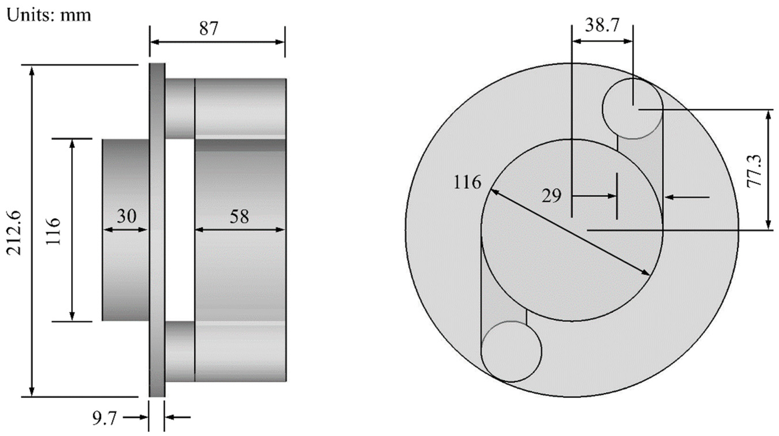
Figure 1 depicts the overall structure of the supersonic swirl separator. It is mainly composed of a swirler, stable section, a supersonic nozzle, a diffuser, and a separator, each with distinctive functions. The principle is that natural gas generates a swirl from the swirler and then passes through the stable section to form a uniform swirl in the supersonic nozzle; this mainly reduces turbulence pulsation in the nozzle. Subsequently, the gas stream spontaneously condenses into small droplets in the low-temperature and low-pressure environment of the nozzle and the small droplets then flow to the separator under the influence of the swirling flow. Finally, dry natural gas is reduced by a diffuser to meet the requirements of pipeline transportation, and pressure energy is recovered to avoid large energy loss. The strength of swirl generated by the swirler directly affects the separation performance. In this paper, the concept of a new swirler is proposed to obtain a stronger swirl. The geometric structure is shown in Figure 2. The number of inlet ports is tentatively set at two, which will be further optimized later. The total length of the supersonic swirl separator was 1133 mm, including a stable section of 58 mm, a nozzle contraction section of 108 mm, an expansion section of 500 mm, a throat diameter of 24 mm, and a nozzle outlet to throat area ratio of 1.27.
Figure 1.
Overall geometric model of supersonic swirl separator.
Figure 2.
Geometric model of swirler.
3. Mathematical Model
3.1. Continuous Phase
Considering that condensed droplets can also affect the gas phase, the bi-coupling model of gas phases and discrete phase droplets are adopted here, and the internal gas phase flow is constrained by the following equation.
Continuity equation:
Momentum equation:
Energy equation:
where ρ and p is the gas density and static pressure; uj and ui are the components of the gas velocity; qj is heat flux; δij is the Kronecker delta; τij is the viscous stress; μ is the dynamic viscosity coefficient; E is the total energy; F is the force of the droplet on the gas phase; Sh is the heat transferred by the droplet to the gas phase.
The ideal gas state equation of P = ρRT is selected in this study.
3.2. Turbulence Model
In view of the realizable k–ε turbulence model, which can accurately predict vortices, strong streamline bending, channels and boundary layer flows [12], and simulation calculations are carried out.
Turbulent kinetic energy k:
Dissipation rate ε:
where μt is the coefficient of turbulence viscosity; Gk and Gb are the turbulent kinetic energy generated by average velocity gradient and buoyancy, respectively; σk and σε are the turbulent Prandtl number of turbulent kinetic energy and dissipation rate, respectively; σk = 1, σε = 1.2; YM is the contribution of compressible turbulent pulsation expansion to the total dissipation rate; C1ε = 1.44, C2 = 1.9, C3ε = 1.3.
3.3. Discrete Phase
Under the low-temperature and low-pressure conditions provided by the supersonic swirl separator, the water vapor in natural gas condenses into small droplets with volume concentrations far less than 10%, meeting the applicable DPM conditions. Therefore, the condensed droplets are regarded as discrete phase particles for numerical simulation, and the following assumptions are made:
- (1)
- The droplet particles are rigid spheres in the process of movement, without considering the growth process of the droplet.
- (2)
- Since the location of the shock wave is controlled in the separator and diffuser, the droplet will not be affected by the shock wave in the separation process of the nozzle, so the droplet evaporation phenomenon caused by the shock wave is not considered.
- (3)
- The friction and collision between droplets are ignored.
When small droplets flow in the supersonic swirl separator, they will be affected by gravity, buoyancy, and drag force. In addition, due to the uneven distribution of airflow velocity and pulse flow, droplets will also be affected by the virtual mass force, basset force and Saffman lift force [13]. The combined effect will make the force of droplets more complicated. Generally, droplet forces are divided into fluid resistance (drag force) FD, virtual mass force FA, gravity force FG, brown force FO, pressure gradient force FP, basset force FH and Saffman lift force FL. According to Newton’s second law, the force model of the droplet can be expressed as:
In view of the problem with many kinds of forces and complexity, some small and complex forces are ignored here. Because the centrifugal force is much greater than gravity, the effect of gravity on droplet motion is ignored. Since brown force almost does not exist in turbulent flow and the Reynolds number at the nozzle throat has reached about 6 × 10⁵, the brown force on the droplet is ignored. The ratio of natural gas density to droplet density is in the order of 10−3, and the relative acceleration between the gas phase and the droplet is small, so the effect of the virtual mass force and the basset force on droplet motion is not considered. In the process of liquid droplets flowing in a supersonic swirl separator, the fluid resistance always plays a dominant role, so the fluid resistance acting on the droplets needs to be considered. The expression FD of fluid resistance per unit of mass received by the droplet is:
At present, the drag calculation method for rigid spheres is becoming more and more popular. The fitting correlation formula of drag coefficient CD, compiled by Wang [14], is chosen in this study. Its error range is −3.78%~+6.18%, and the average absolute error is only 2.06%, which can meet the calculation requirements of droplet flow. The fitting correlation formula is expressed as:
In the supersonic swirl separator, due to the existence of a large pressure gradient, the droplet is subjected to a force in the opposite direction of the gradient, so the effect of the pressure gradient force cannot be ignored. The expression of pressure gradient force FP per unit of mass is:
In addition, owing to the effect of swirling, the condensed droplets are subjected to strong shear force. Therefore, it is necessary to consider the effect of the Saffman lift force on the droplet. The expression of Saffman lift force FL per unit of mass is:
Finally, by simplifying the force model and considering only fluid resistance, pressure gradient and Saffman lift forces, the governing equation of the droplet is as follows:
Considering that the gas phase turbulence pulsation in a supersonic swirl separator can cause the diffusion of droplets, there are two particle tracking models used to predict the particle diffusion, namely the random walk model and the particle cloud model. The particle cloud model is used to track the droplet in a steady state by statistically obtaining the average velocity of particles; therefore, it is not suitable for unsteady calculations. The random walk model uses instantaneous turbulence velocity fluctuation to draw statistics on the droplet trajectory. As unsteady computation is required in this study, the random walk model was chosen to calculate the droplet diffusion caused by airflow turbulence. Gas phase velocity u is expressed as:
The Rosin—Rammler model [10] is adopted to describe the particle size distribution of the droplets, and the mass fraction Yd with a droplet diameter larger than d is:
In summary, by a dedicated simplification of the force model of droplets and carrying out an integral calculation considering the random walk model of droplet diffusion caused by gas turbulence pulsation, the flow process of droplets condensing from water vapor into different particle size distributions in the supersonic swirl separator can then be predicted.
4. Numerical Methods and Boundary Conditions
The supersonic swirl field belongs to the high-speed compressible flow, so this paper selects the density-based implicit algorithm, which is more accurate and stable for the high-speed compressible flow. In order to ensure the accuracy of the calculation, the flow equations in the calculation are discretized by the second-order upwind scheme.
The boundary conditions were pressure inlet, pressure outlet and non-slip, adiabatic wall, in which total inlet pressure p0 = 170 kPa, total inlet temperature T0 = 300 K, dry outlet pressure pout_d = 100 kPa and wet outlet pressure pout_w = 60 kPa.
The boundary conditions of the discrete phase were: the section (Z = 220 mm) at the end of droplet nucleation in the experimental nozzle [15] was selected as the droplet incidence plane, which means that there will be no droplet in the future. The boundary condition of the dry gas outlet was set as particle escape; that is, when the droplet reaches this boundary, the tracking calculation will stop. The boundary conditions of the wet outlet and separator wall were set as the particle trap, to calculate the number of droplets separating. The wall boundary condition of the nozzle expansion section was also set as the particle trap, because in the nozzle expansion section, droplets are “thrown” to the wall under the action of centrifugal force and finally form a layer of liquid film separated from the drain port. The other wall boundary conditions were set to reflect; that is, after the droplet reached the boundary, it reflected and re-entered the main stream.
5. Grid-Independence Verification
The internal flow process of supersonic swirl separators is extremely complex, and a higher-quality grid is needed to ensure the efficiency of the calculations and accuracy of results. In view of the advantages of structured grids, such as higher quality and easier convergence, this study adopts a structured grid to grid the calculation domain. In addition, the flow near the wall varies greatly, especially when the transonic velocity is involved in the supersonic nozzle. The boundary layer of the wall is encrypted with mesh, and the height of the first layer of mesh at the nozzle throat is 0.35 mm. Under the premise that the mesh division method is unchanged, in order to avoid the influence of the number of grids on the subsequent simulation results, grid independence verification was first carried out.
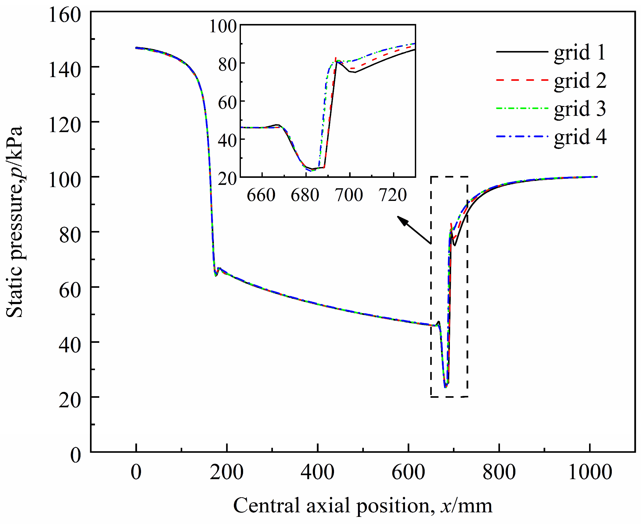
Figure 3 compares the static pressure distributions along the nozzle central axis under four different mesh densities (grid 1, grid 2, grid 3 and grid 4). The grid cells are 1,303,107, 1,663,549, 2,065,315 and 2,479,095, respectively. It can be seen that when the grid density is small, the static pressure distribution after the shock wave position appears as a relatively obvious bulge phenomenon, which in fact does not exist. This phenomenon is due to the numerical error caused by the discrete method and the grid density, also known as numerical dispersion. As the grid density increases, the numerical dispersion phenomenon weakens, and the calculation results tend to be identical. In particular, when the grid density reaches grid 3, the dispersion phenomenon is basically eliminated, and the maximum error between the grid density and the calculation results of grid 4 is less than 1.5%. Therefore, considering the time cost and calculation accuracy comprehensively, the medium density of grid 3 was finally adopted for the subsequent calculation research in this paper. The specific grid distribution is illustrated in Figure 4.
Figure 3.
Static pressure distribution along the nozzle central axis under four different mesh densities.
Figure 4.
Grid distribution of supersonic swirl separator: (1) global grid, (2) local grids at A–B and C–D location, respectively.
6. Performance Index
In order to quantify the system performance of the supersonic swirl separator, the effects of key parameters on the overall performance were investigated. In this paper, on the basis of separation efficiency, multiple visual parameters such as shock location (distance between positive shock wave and nozzle exit section), separation temperature and mass flow ratio in the diffuser are evaluated as indexes for comprehensive evaluation. Among them, the separation efficiency is used to evaluate the separation performance of the supersonic swirl separator; that is, as one of the most critical parameters to evaluate overall system performance. Its definition is as follows:
where η is the separation efficiency; qm,trap is the mass flow rate of the collected droplets; qm,escape is the mass flow rate of the escaped droplets in the diffuser; qm = qm,trap + qm,escape; ms is the mass of droplet collected in Δt time after convergence of flow field.
Mass flow ratio is used to evaluate the proportion of dry gas flowing out of the supersonic swirl separator, that is, the economy of the supersonic swirl separator. Its definition is as follows:
where ε is the mass flow ratio of the gas; Qm,in is the mass flow rate of the inlet gas; Qm,wet is the mass flow rate of gas at the wet exit of the separator; ρi, , are the density, velocity and area on the ith grid surface in the inlet or wet outlet cross section, respectively.
The shock location ST1 (the distance between the positive shock wave and the nozzle outlet section) in the diffuser is used to evaluate the expansion and condensation effect of the supersonic nozzle. The separation temperature is used to ensure the low-temperature and low-pressure environment in the supersonic nozzle, and it provides the basis for the normal operation of the separator and the whole device pressure range.
7. Droplet Trajectory Analysis
When the simulated droplet is injected from the section Z = 220 mm, the material of the droplet is liquid water, and the density and specific heat capacity of the droplet are 998.2 kg/m3 and 4182 J/(kg·K), respectively. The inlet mass flow rate of the droplet is calculated as qm = 1 × 10⁻³ kg/s [15]. In addition, the condensation velocity of the droplet is similar to that of the gas, as is the temperature. Therefore, the incident velocity and temperature of the droplet are taken from the average velocity and temperature of the gas of the section, which are 451.4 m/s and 253.5 K, respectively.
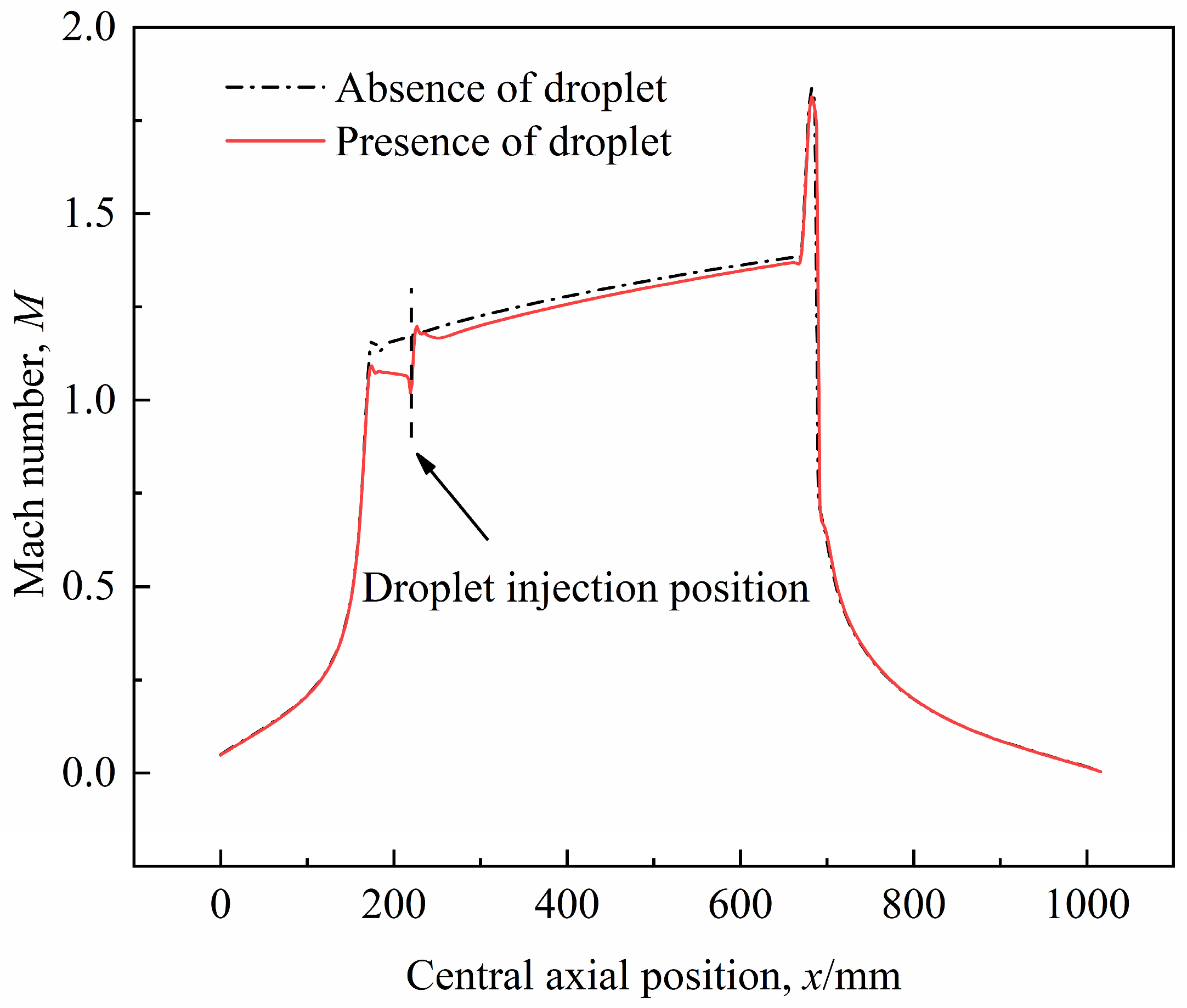
Figure 5 shows the Mach number distribution on the central axis of the supersonic swirl separator in the presence and absence of droplets. It can be found that in the absence of droplets, the airflow expands along the nozzle axis into a supersonic state and returns to the subsonic state again after passing through a positive shock wave in the diffuser. However, when droplets are injected from the specified section Z = 220 mm, the Mach number distribution along the central axis in the nozzle changes slightly compared with that in the case without droplets. This is due to the drag effect of droplets on the gas, which reduces the expansion effect of the gas, so the Mach number in the case with droplets in the same position is lower than that in the case without droplets. It is worth noting that the Mach number of the airflow appears to have a small sudden drop at the position of the droplet injection, which is mainly caused by two aspects. On the one hand, the process of droplet condensation and growth is ignored in the mathematical model, and the droplet condensation is considered to have been completed. When the droplet is injected, the airflow will generate shock waves in front of the droplet, resulting in the Mach number of the airflow plummeting to 1.02. On the other hand, because the injection position of the droplet is close to the throat, the gas expands from a subsonic to a supersonic state just after passing through the throat, and the maximum Mach number is only 1.07. At this time, the incoming Mach number of the airflow is low, and the shock wave intensity generated in front of the droplet is weak, which ultimately leads to a small drop in the Mach number of the airflow before the droplet injection position. After that, the airflow continues to expand along the axial direction, where the “convex spot” phenomenon appears in the Mach number distribution due to the influence of numerical dispersion.
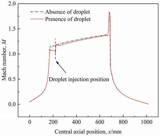
Figure 5.
Mach number distribution on the central axis of the supersonic swirl separator in the presence and absence of droplet.
Figure 6 presents the trajectory diagram of droplets with different diameters in the supersonic swirl separator. One can see that condensed droplets with different diameters also start to make a combined spiral vortex motion under the combined action of drag force, pressure gradient force and Saffman force. Part of the droplet is separated from the separator, while the other part is discharged from the diffuser with dry gas. It then provides a reliable condition for the separation of droplets.
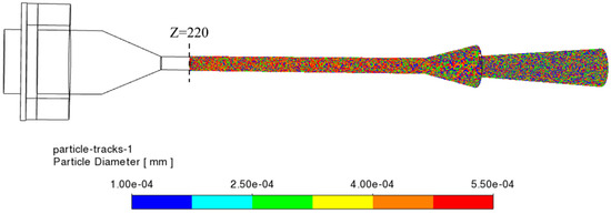
Figure 6.
Trajectory diagram of droplets with different diameters in a supersonic swirl separator.
Figure 7 and Figure 8 compare two typical tracks of the droplets, with the largest and smallest diameters (ID = 291 and ID = 7000) injected from the specified positions, respectively. In Figure 7, the radial position of the droplets injected is close to the nozzle wall, and the tangential velocity near the wall is larger [16]. The centrifugal effect on the large droplets with a diameter of 0.55 μm is much greater than the inertial effect caused by the axial velocity, so they are all “thrown” out of the original orbit to the nozzle wall, where the droplets gather to form liquid film and finally flow into the separator. Shown differently in Figure 8, the radial location of the droplets injected is in the central area of the nozzle, and the tangential velocity of the central area is very small. As a result, the small droplets with a diameter of 0.1 μm are mainly subjected to the inertial effect caused by the axial velocity in the nozzle, and the vortex phenomenon of the droplets is not obvious. As a result, the small droplets in the central area will basically escape from the dry outlet of the diffuser with the airflow, so the separation is incomplete. This is one of the disadvantages of the front-mounted supersonic swirl separator in terms of separation performance, which is also the fundamental reason why the interpolation separator was introduced in this paper and the subsequent structural improvement was carried out. In addition, droplets will be diffused by gas phase turbulent pulsation in the process of movement, and the degree of diffusion is proportional to the velocity of turbulent pulsation. In the nozzle, the influence of turbulent pulsation on droplets is relatively small. The trajectory of small droplets in the central region is still maintained near the central region, and only a few droplets are diffused from the nozzle outlet to the separator. In the diffuser, the turbulence pulsation increases due to the influence of a positive shock wave, which can improve the non-uniformity of the droplet flow in the diffuser.
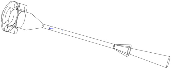
Figure 7.
A droplet trajectory with a diameter of 0.55 μm (ID = 291) injected from a specified location.
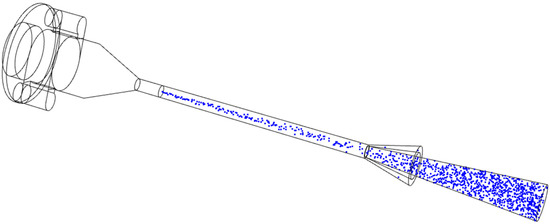
Figure 8.
A droplet trajectory with a diameter of 0.1 μm (ID = 7000) injected from a specified location.
8. Results and Discussion
By changing the number of inlet ports of the swirler, the gas-liquid area ratio and deflection angle of separator, the influences of different structural parameters on the system performance of the device were studied. The separation efficiency, separation temperature, shock location in the diffuser and mass flow ratio were taken as evaluation indexes for optimization analysis, and a more reasonable structural size of the swirler and separator was determined by comprehensive consideration. On this basis, we continue to discuss the wet pressure ratio, pressure boost ratio and particle size factors on the device system performance, in order to further determine a means of improving the system performance and the operating pressure range of the device.
8.1. The Effect of the Number of Inlet Ports
The swirl generated by the swirler is the key to the separation of condensate droplets, and the number of inlet ports in the swirler plays a decisive role in the swirler. In order to study the influence of the number of inlet ports on the system performance, three groups of inlet number (No) were taken to simulate the flow field, and the structure size of the separator remained unchanged. The specific initial conditions are listed in Table 1:

Table 1.
Initial condition for the simulations of the inlet ports studies.
Figure 9 shows the variation diagram of separation efficiency and shock wave location in the diffuser (distance between positive shock wave and nozzle outlet section) with the number of inlet ports. It can be seen that when the number of inlet ports is two, the separation efficiency is 54.3%, and the distance between the positive shock wave position in the diffuser and the nozzle outlet section is 16.13 mm. With the increase in the number of inlet ports, the separation efficiency decreases almost linearly—especially when the number of inlet ports is six, the separation efficiency is only 35%. However, the distance between the positive shock wave position in the diffuser and the nozzle outlet section keeps increasing, but when the number of inlet ports increases from four to six, the distance increase gradually decreases, with a difference of about 5 mm between the two. This is because the change in the number of inlet ports directly affects the tangential velocity of the overall flow field (Figure 10), thus changing the centrifugal effect on the droplets. Meanwhile, the generation of swirling flow weakens the expansion and condensation effect of the nozzle. Specifically, with the decrease in the number of inlet ports, the swirl provides stronger tangential velocity to the fluid, thus enhancing the centrifugal effect on the droplets and improving the possibility of separating the droplets in the center area of the nozzle from the wet outlet of the separator. At the same time, when the number of intakes decreases, the swirls generated within a certain range have little influence on the expansion and condensation effect of the nozzle [17]. Beyond this range, stronger swirls have a more obvious inhibition effect on the expansion and condensation effect of the nozzle. Therefore, when the number of intakes decreases to two, the huge swirl generated will lead to the shock waves occurring in the diffuser in advance.
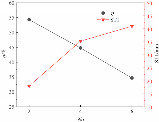
Figure 9.
Variation diagram of separation efficiency and shock wave location in the diffuser, with the number of inlet ports.
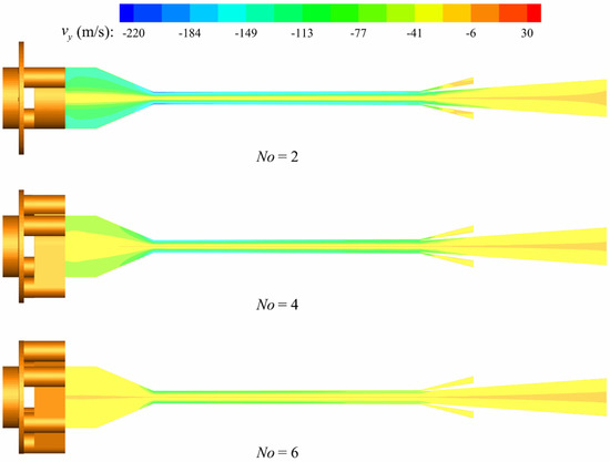
Figure 10.
Tangential velocity profile of supersonic swirl separators with different numbers of inlet ports.
Figure 11 plots the variational diagram of the mass flow ratio and separation temperature with the number of inlet ports. The decrease in the number of inlet ports affects the decline of mass flow ratio and separation temperature to some extent, but the decrease is small—the mass flow ratio remains around 72% and the separation temperature is around 232 K.
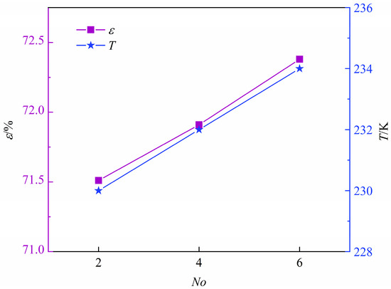
Figure 11.
Variation diagram of mass flow ratio and separation temperature, with the number of inlet ports.
Considering the influence of the number of inlet ports on the system performance, in order to make the fluid obtain a larger swirl for improving the separation efficiency and to ensure that the swirl has less influence on the expansion and condensation effect of the nozzle, the swirler with four inlet ports was finally selected as the optimal size.
8.2. The Effect of Gas-Liquid Area Ratio
The outlet of the supersonic nozzle is connected to the inlet of the separator (drain port) and the inlet of the diffuser at the same time. The liquid drops flow into the separator from the drain port, while the dry gas flows into the diffuser from the inlet of the diffuser. The inlet area of the diffuser and the area of the annular drain port are defined as the gas-liquid area ratio Sqy. In order to study the effect of the gas-liquid area ratio on system performance, five groups of different gas-liquid area ratios were numerically simulated, and the other parameters remained unchanged. The specific initial conditions are given in Table 2:
Table 2.
Initial condition for the simulations of the gas-liquid area ratio cases.
Figure 12 shows the profiles of the separation efficiency and mass flow ratio along with the gas-liquid area ratio. It can be seen that when the gas-liquid area ratio is 3.02, the separation efficiency is the minimum while the mass flow ratio is the maximum; the results were 49.9% and 79.77%, respectively. With a decrease in the gas-liquid area ratio, the separation efficiency increases, but the mass flow ratio decreases. When the gas-liquid area ratio is 0.54, the separation efficiency reaches 77.3% and the mass flow ratio is only 39.18%. This is due to the decrease in the gas-liquid area ratio, namely, the increase in the area of the annular drain port, so the droplets that are not able to be separated due to the centrifugal effect can also have the opportunity to be separated from the separator, so as to improve the separation efficiency. At the same time, the reduction in the gas-liquid area ratio also means that the diffuser inlet area decreases, thus reducing the possibility of air flow out of the diffuser. When it is reduced to a certain extent, only a small amount of dry gas flows out of the diffuser outlet, which is very uneconomical in engineering.
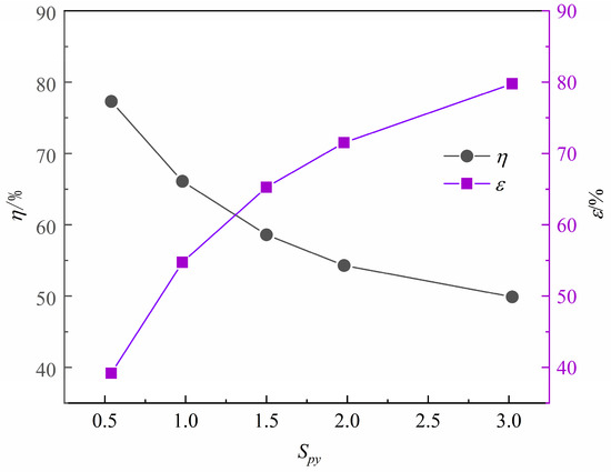
Figure 12.
Profiles of the separation efficiency and mass flow ratio with gas-liquid area ratio.
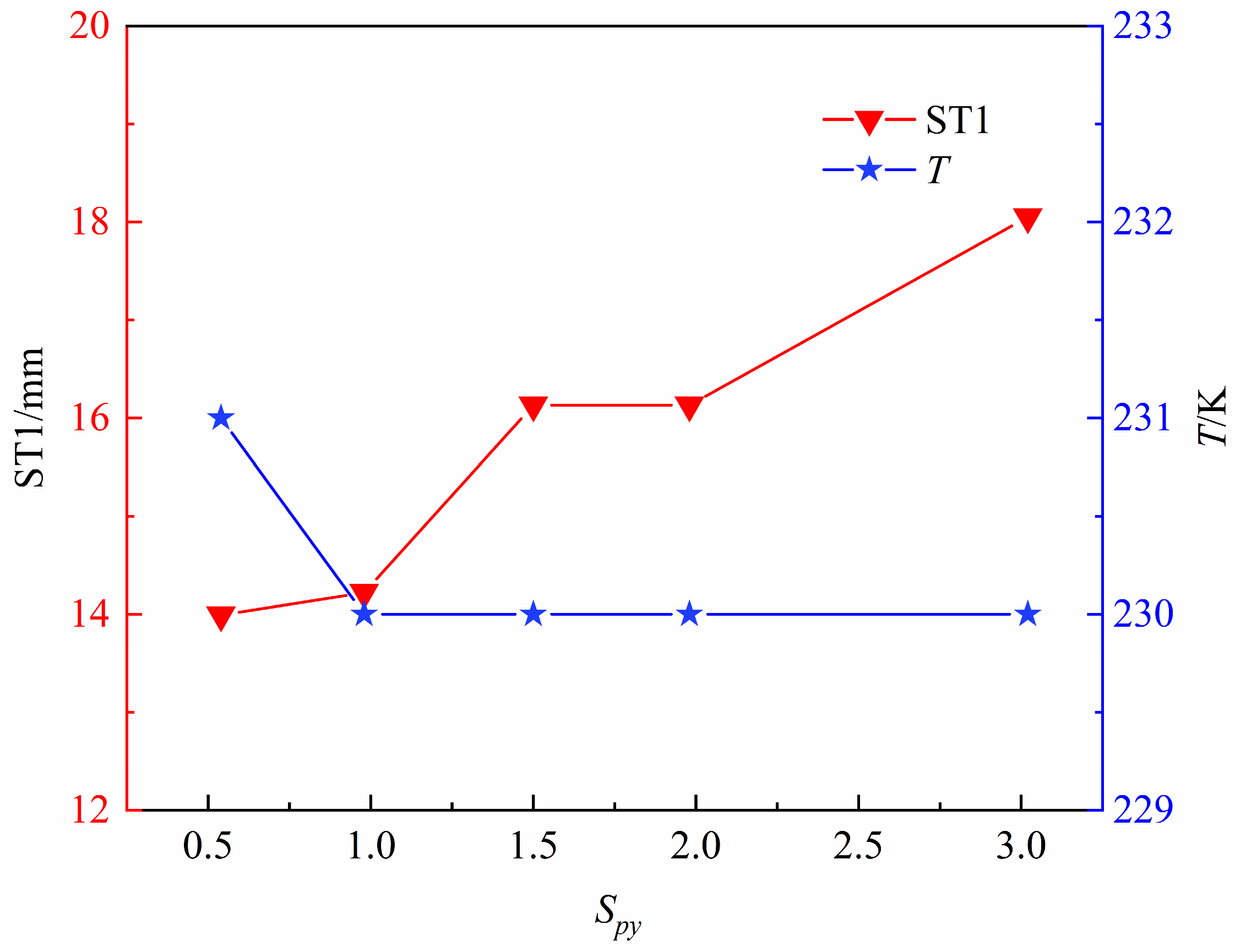
Figure 13 depicts the variation diagram of shock wave location in diffuser (distance between positive shock wave and nozzle outlet section) and separation temperature in diffuser with gas-liquid area ratio. It can be seen that the decrease ingas-liquid area ratio reduces the shock wave position in diffuser to a certain extent and has almost no influence on separation temperature. This is because on the premise that the expansion angle of the diffuser in this paper remains unchanged, the gas-liquid area ratio decreases, which also means that the ratio between the outlet area and the inlet area of the diffuser increases. According to the quasi-one-dimensional variable section isentropic tube flow theory, the ratio between the outlet area and the boost ratio plays a decisive role in the location of shock waves, and the boost ratio in this section remains unchanged. Therefore, the location of shock wave will move forward with the increase in the area ratio of inlet and outlet. In addition, the shock wave generated in the diffuser has no impact on the low-temperature and low-pressure environment in the nozzle, and the separation temperature is maintained at 230 K.
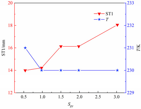
Figure 13.
Variation diagram of shock wave location in diffuser and separation temperature with gas-liquid area ratio.
Considering the influence of the gas-liquid area ratio on the system performance, it is reasonable to take the gas-liquid area ratio Sqy = 1.5, which not only ensures the separation performance of the device, but also enables enough flow of dry gas to flow out from the diffuser outlet, thus improving the economy of the device during operation.
8.3. The Influence of Deflection Angle
Deflection angle is also one of the important parameters to be considered in the separator. Here, the angle between the center line of the separator inlet and the center axis of the nozzle is defined as θ. In order to study the influence of separator deflection angle on system performance, five groups of deflection angle were selected for numerical simulation, and other parameters remained unchanged. The specific initial conditions are shown in Table 3:
Table 3.
Initial condition for the simulations of the deflection angle cases.
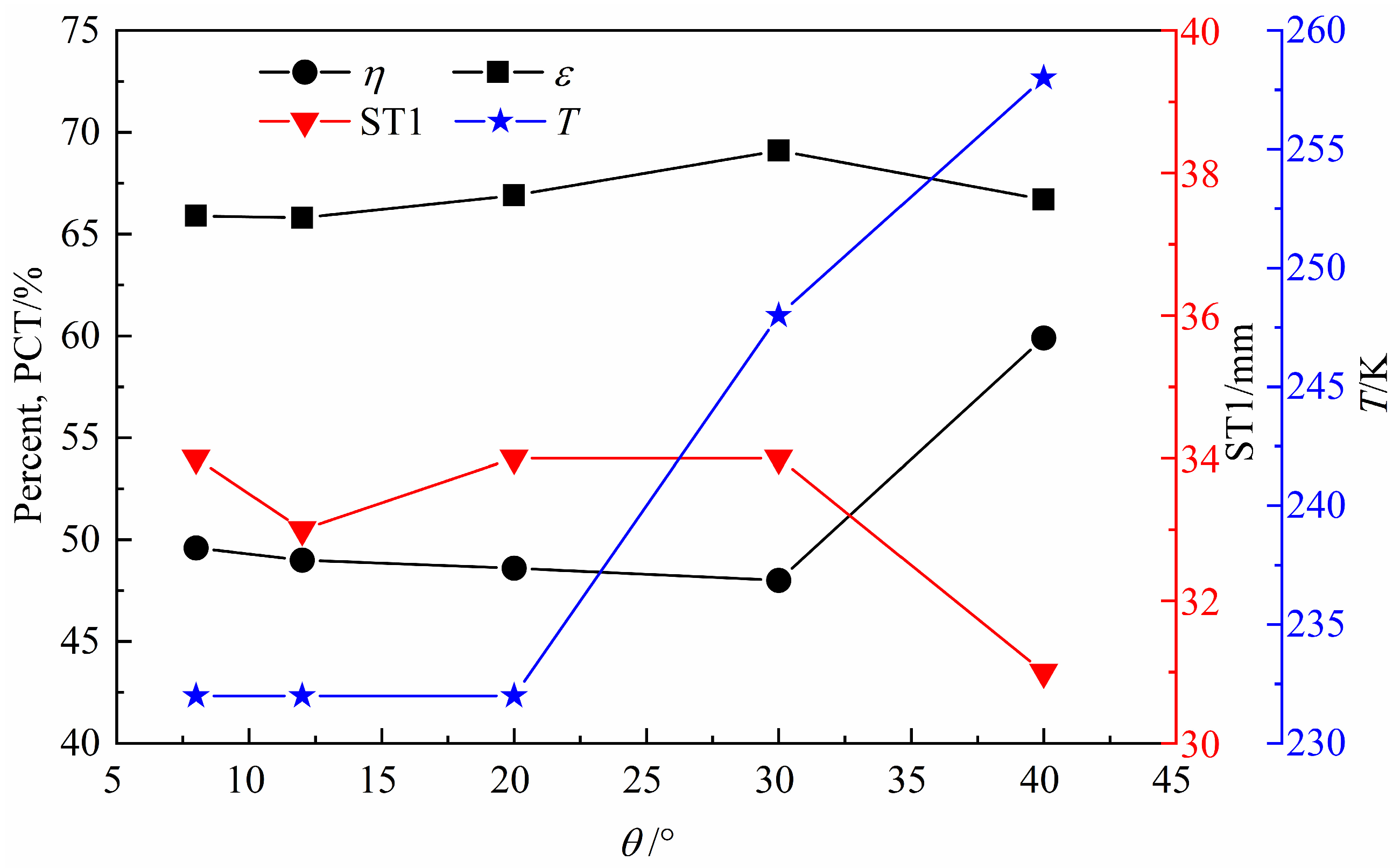
The variation diagram of four indexes with the deflection angle is shown in Figure 14. Firstly, it can be seen that when the deflection angle is less than 20°, the separation temperature is not affected by the deflection angle, while when the deflection angle is more than 20°, the separation temperature rises linearly, especially when the deflection angle is 40°, the separation temperature reaches 258 K, which has completely destroyed the low-temperature conditions in the droplet condensation process. That means the dehydrator failed. Secondly, when the deflection angle is lower than 30°, the separation efficiency decreases to a certain extent, and the mass flow ratio is vice versa. The shock wave location in the diffuser (the distance between the positive shock wave and the nozzle outlet section) is less affected by the deflection angle and is maintained at about 33.5 mm. As the deflection angle exceeds 30°, the separation efficiency increases obviously. Meanwhile, the mass flow ratio and the shock wave location in the diffuser decrease.
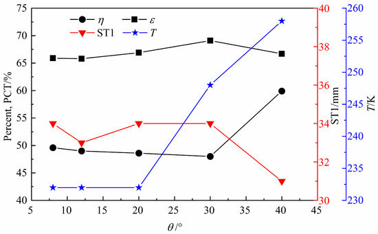
Figure 14.
Variation diagram of four indexes with the deflection angle.
Due to the influence of the deflection angle, the geometrical section of the nozzle outlet connecting with the separator changes dramatically, resulting in a drastic rearrangement of the flow line from the nozzle outlet to the separator, which further affects the change of local resistance to the separator and promotes the outflow of air from the dry outlet. When the deflection angle is less than 20°, with the increase in deflection angle, the increase in local resistance is relatively small, which means that the mass flow ratio at this stage only increases slightly, and the separation efficiency is vice versa. At the same time, it means that the local drag has little influence on the mainstream region, so that the shock wave location and separation temperature in the diffuser are basically unchanged. When the deflection angle increases to 30°, the local resistance further increases, resulting in the formation of new compression waves near the outlet of the supersonic nozzle (Figure 15). The existence of compression waves in the nozzle destroyed the low-temperature and low-pressure environment of condensation in this paper, and the air temperature kept rising after passing through the compression waves. Therefore, the separation efficiency did not drop sharply as a result, but still maintained the previous small decrease rule, which also indicated the importance of other evaluation indicators. When the deflection angle continues to increase to 40°, the larger local resistance makes the shock wave position more advanced, and the separation temperature further increases. At this time, the separation efficiency does not decrease, but significantly increases. This is because on the one hand, when the airflow passes through the shock wave, it will reduce its axial momentum and generate stronger tangential momentum (Figure 16). On the other hand, the shock wave occurs far away from the nozzle outlet, which makes the droplet rotate near the wall for a long time. The combined influence of the two causes the separation efficiency to increase significantly.
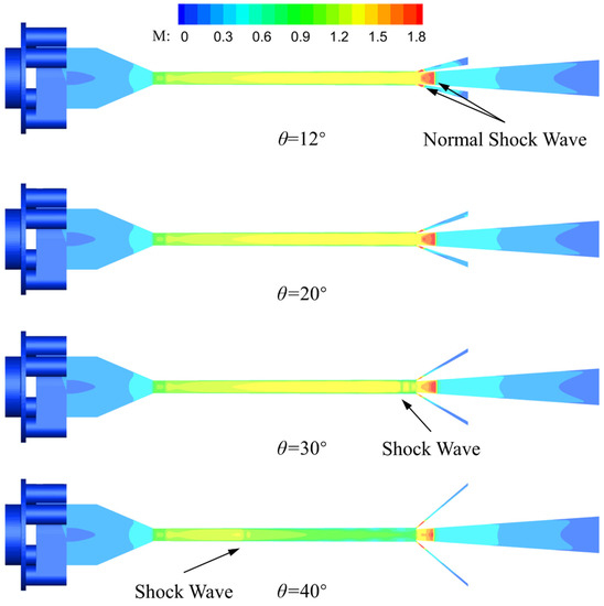
Figure 15.
Mach number profile of supersonic swirl separators with different deflection angles.
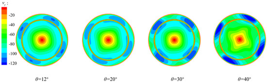
Figure 16.
Tangential velocity profile of nozzle outlet section with different deflection angles.
Considering the influence of the deflection angle of the separator on the system performance, mainly considering the influence of the deflection angle on the separation temperature, it is reasonable to take the deflection angle of 12°, which not only ensures that no sub-shock wave is generated in the nozzle, affecting the low-temperature and low-pressure environment of water vapor condensation, but also saves the installation space of the device.
8.4. The Effect of Wet Pressure Ratio
We set out to study the influence of wet outlet pressure on system performance and determine the normal working pressure range of the separator, so as to obtain a larger wet outlet pressure and reduce the energy loss of the separator. Here, the ratio of the wet outlet pressure to the total inlet pressure was defined as the wet pressure ratio φ, six groups of wet pressure ratios were selected for numerical simulation, and other parameters remained unchanged. The wet pressure ratio reflects the pressure loss characteristics of the separator. The larger the wet pressure, the smaller the pressure loss of the separator. The specific initial conditions are listed in Table 4:
Table 4.
Initial condition for the simulations of the wet pressure ratio cases.
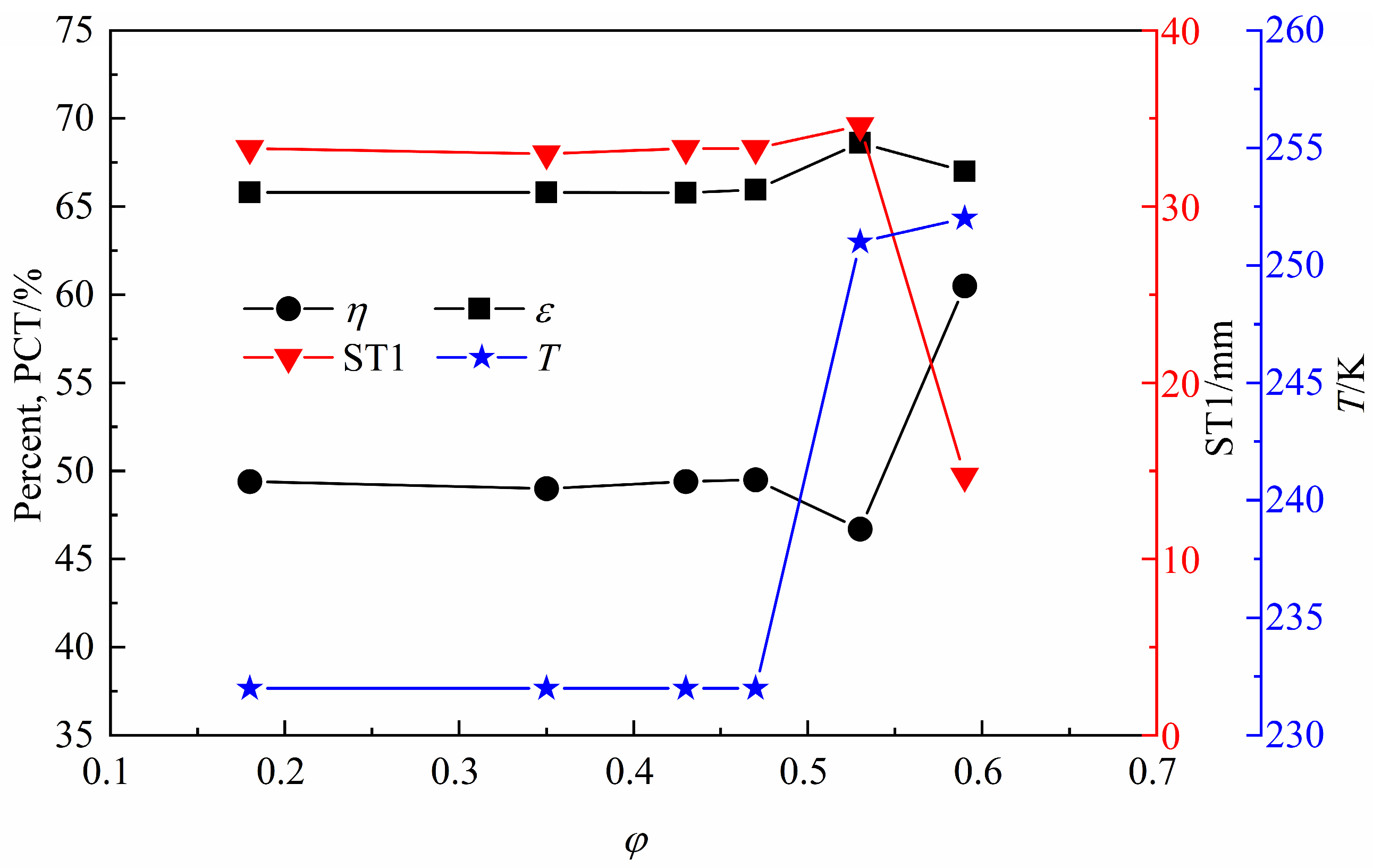
Figure 17 plots the variation diagram of four indexes with the wet pressure ratio. It can be seen that when the wet pressure ratio is lower than 0.47, the influence of the four indicators on the wet pressure ratio is negligible. However, with the increase in wet pressure ratio, the change trend of each index is very obvious. First, the separation temperature maintained an upward trend; secondly, the separation efficiency showed a trend of decreasing first and then increasing; and lastly, the mass flow ratio was inversely related to the shock wave location in the diffuser (the distance between the positive shock wave and the nozzle outlet section).This is because when the wet pressure ratio is lower than 0.47, the drain port pressure is lower than the wet outlet pressure, and there is an adverse pressure gradient between them, resulting in positive shock waves being generated by the separator to balance the pressure before and after. In this stage, as the wet pressure ratio keeps increasing, the adverse pressure gradient between them also keeps increasing. At this time, the occurrence position of the positive shock wave in the separator keeps moving forward until it increases to 0.47, and the occurrence position of the positive shock wave is basically at the entrance of the separator (Figure 18).
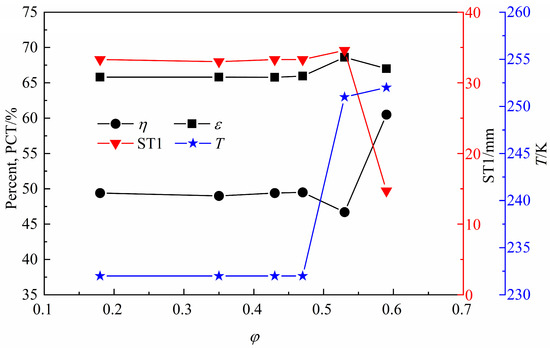
Figure 17.
Variation diagram of four indexes with the wet pressure ratio.
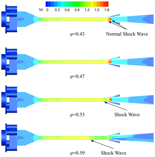
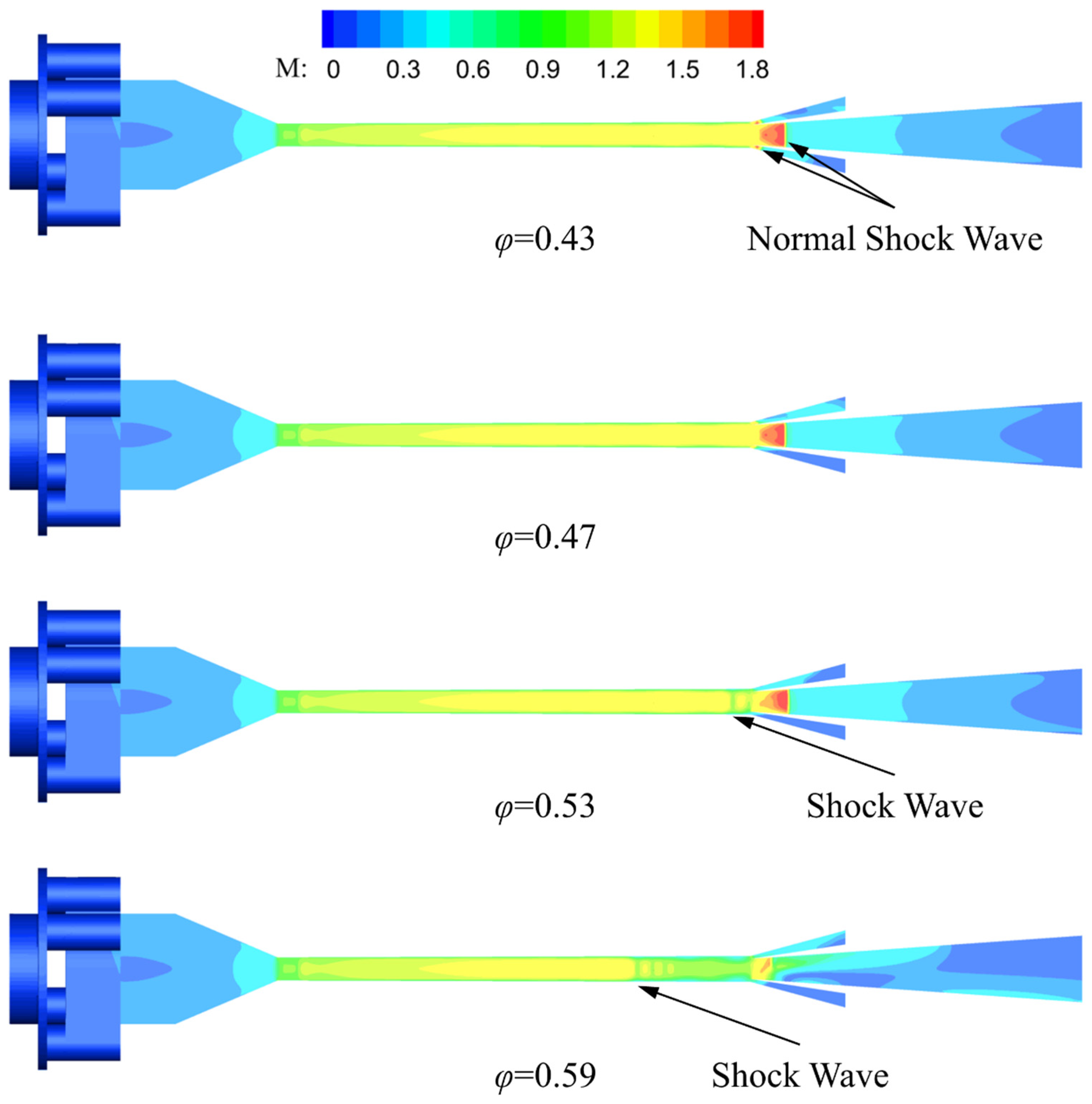
Figure 18.
Mach number profile of supersonic swirl separators with different wet pressure ratios.
This stage has no influence on the mainstream area. When the wet pressure ratio increases to 0.53, the adverse pressure gradient further increases, and the larger adverse pressure gradient will continue to push the positive shock wave to move forward to the nozzle expansion section to form a new compression wave. At this time, the air flow passing through the shock wave will inevitably cause the temperature to rise and destroy the low-temperature and low-pressure environment of the droplet. Similarly, the influence of the droplet heating and evaporation in the model is not taken into account, so the separation efficiency does not drop sharply. However, the larger adverse pressure gradient forces the air flow out from the dry outlet, resulting in a small increase in the mass flow ratio, and the separation efficiency is vice versa. When the wet pressure ratio continues to increase to 0.59, the shock wave location in the nozzle keeps moving forward to the nozzle throat. At this stage, the separation efficiency increases instead of decreasing, for the same reason as in the above section. When the air flow passes through the shock wave, its axial momentum will be reduced, a stronger tangential momentum will be generated, and the centrifugal force on the droplet will be improved. The droplet rotates near the wall for a long time, and the two jointly influence the separation efficiency, as shown in Figure 19.
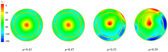
Figure 19.
Tangential velocity profile of nozzle outlet section with different wet pressure ratio.
Considering the influence of the wet pressure ratio on the four indexes, the wet pressure ratio should not exceed 0.47 under the normal operation of the separator. In this stage, the wet pressure ratio will not affect the mainstream area. When the wet pressure ratio exceeds 0.47, sub-shock waves will appear in the mainstream area of the nozzle, causing the separation temperature to rise, seriously weakening the cooling effect of the nozzle and finally leading to the loss of the separation effect of the device.
8.5. The Effect of the Boost Ratio
Compared with the wet outlet pressure, the dry outlet pressure is more important. This is because the dry outlet conveying dehydrated natural gas requires a larger dry outlet pressure to ensure the power in transportation. Therefore, the dry outlet pressure range under normal operation should be obtained to avoid the waste of energy to the greatest extent. The ratio of dry outlet pressure to inlet pressure was defined as boost ratio γ. Six groups of different boost ratios were used for numerical simulation, and other parameters remained unchanged. We can refer to Table 5 for specific initial conditions:
Table 5.
Initial condition for the simulations of the boost ratio cases.
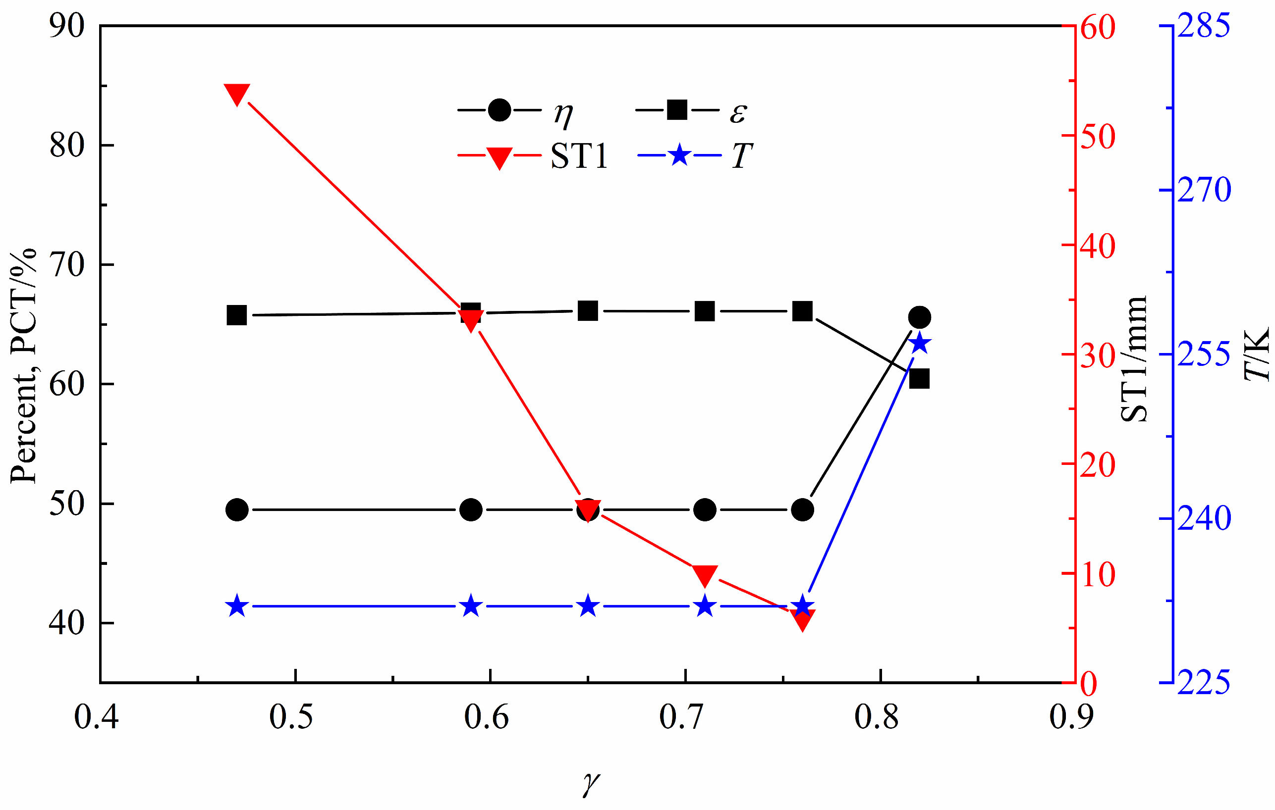
Figure 20 presents the variation diagram of four indexes with the boost ratio. It can be seen that when the boost ratio is less than 0.76, the change of the boost ratio basically has no impact on the separation efficiency, mass flow ratio and separation temperature. This feature of the new supersonic swirl separator in this paper is very conducive to the separation of condensable gas in gas fields in different scenarios, which can achieve similar and efficient overall performance and has a wide range of application scenarios. In addition, in this range, the increase in the boost ratio will lead to a constant reduction in the shock wave location in the diffuser (the distance between the positive shock wave and the nozzle outlet section). In particular, when the boost ratio is 0.76, the shock wave location is only 6 mm away from the nozzle outlet section. When the boost ratio exceeds 0.76, the separation efficiency and separation temperature rise significantly, while the mass flow ratio exhibits the opposite response. The shock wave occurs in the expansion section of the supersonic nozzle in the diffuser. This is because there is a reverse pressure gradient in the diffuser, resulting in the pressure difference before and after positive shock balance. As the boost ratio increases, the reverse pressure gradient also increases, resulting in the positive shock position constantly moving forward inside the diffuser. However, before the positive shock position reaches the nozzle, it has no influence on the key parameters (separation efficiency, mass flow ratio and separation temperature). When the boost ratio is 0.82, the reasons for the change of evaluation index are the same as in the previous section.
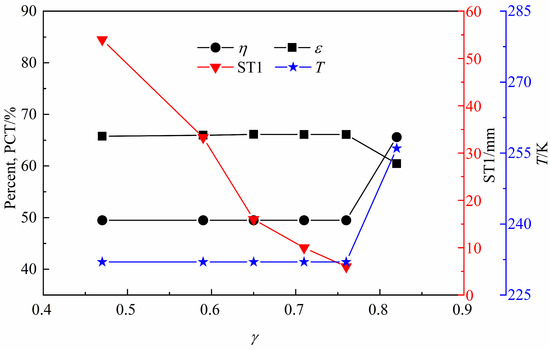
Figure 20.
Variation diagram of four indexes with the boost ratio.
Considering the influence of the boost ratio on the four indexes comprehensively, the boost ratio should be lower than 0.76 under the normal operation of the device, so as to avoid shock waves forming in the supersonic nozzle due to a large boost ratio, resulting in the ineffectiveness of dehydration. In such a pressure range, the system performance can achieve better results.
8.6. Effect of Particle Size
In order to study the influence of droplet diameter on system performance, seven groups of droplets with different sizes were selected for simulation analysis. Other parameters remained unchanged. Specific initial conditions are given in Table 6:
Table 6.
Initial condition for the simulations of the particle size cases.
Figure 21 shows the variation diagram of four indexes with the droplet diameter. One can see that the change of droplet diameter mainly affects the separation performance. As the droplet diameter increases, the separation efficiency increases as well. However, one study [18] found that there is a maximum critical diameter, and when the droplet exceeds the maximum critical diameter, the separation efficiency no longer increases with the change of droplet diameter. It is not difficult to find that there is no maximum critical diameter in this paper. The main reason is that the strength of the swirl generated by the optimized swirler in this paper is strong, so the droplet diameter when completely separated is far less than the maximum critical diameter, which also shows the advantages of the new swirl generator. Under the condition of the low-pressure difference at the inlet and outlet (only 40 kPa), the expansion and condensation effect can be ensured and can provide a swirl strong enough to separate the droplets completely. As for the reason that the separation efficiency increases with the increase in the droplet diameter, it is because the centrifugal force on the droplet is lower than the drag force when the droplet diameter is small, which means that the droplet has a good following property. Especially for the droplet with a small tangential velocity in the nozzle center area, most of the droplet will escape from the dry outlet under the influence of the axial effect, so the separation efficiency is low. With the increase in the droplet diameter, the centrifugal force on the droplet also increases, which means that the droplet’s followability becomes worse. At the same time, the centrifugal force on the droplet is much higher than the inertial force in the movement following the flow line, and the droplet will break away from its original orbit and move closer to the wall until a liquid film is formed on the wall. Finally, the droplet is separated from the wet outlet of the separator. This then improves the separation efficiency.
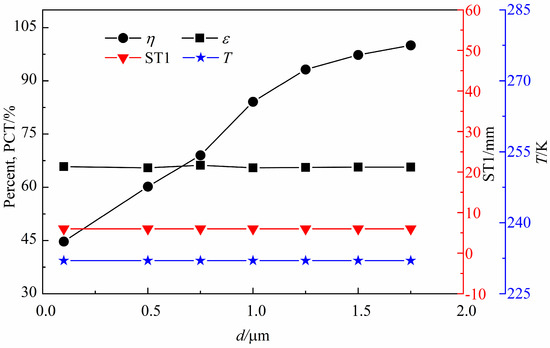
Figure 21.
Variation diagram of four indexes with the droplet diameter.
Therefore, before the operation of the device, it is necessary to increase the diameter of the condensed droplet, and in order to solve this problem, we can start with two aspects: homogeneous nucleation and heterogeneous nucleation. In terms of homogeneous nuclei, the typical size range of spontaneous condensation of water vapor is about 0.1–2 μm, and when the droplet diameter reaches 1.75 μm in this paper, the droplet was completely separated. Therefore, in this paper, the expansion angle of the nozzle can be increased to improve the condensation depth, and then the diameter of water vapor spontaneous condensation into droplets can be increased. In terms of heterogeneous nucleation, Qing [19] proposed that the condensation core be added externally to increase the diameter of condensed droplets.
9. Conclusions
To address existing challenges in the design of supersonic swirl separators, we propose a simple and efficient front-mounted supersonic swirl separator by simplifying the geometric model. A mathematical model is then established to simulate the process of droplet separation inside the devices. Consequently, the influence of structural parameters and operating parameters on the system performance is analyzed in detail. The main findings are as follows:
- (1)
- Due to centrifugal force differences during condensation, there are two typical droplet trajectories. A larger droplet near the nozzle wall can rotate to the wall quickly, forming a liquid film and separating out. However, the vortex phenomenon in the center area is not obvious, which makes most of the smaller droplets escape from the dry outlet.
- (2)
- The system performance of the device is quantified by several performance indicators, such as separation efficiency, shock wave location in the diffuser, separation temperature, mass flow ratio, and the separation performance, expansion condensation effect, condensation environment and economy of the device. With an increase in the number of inlet ports, the separation performance decreases, but the expansion and condensation effects improve. The increase in the gas-liquid area ratio decreases the separation performance and improves the economic performance. When the deflection angle exceeds 20°, a shock wave appears in the nozzle, which can ruin the condensing environment.
- (3)
- Under the normal operation of the device, the range of wet pressure ratio and boost ratio is lower than 0.47 and 0.76, respectively. If it exceeds this range, an additional shock wave can be formed in the nozzle, destroying the condensing environment. Thus, the separation function of the device will be lost. The variation in wet pressure ratio and boost ratio will not affect the system performance. With droplet diameter increased, the separation performance is improved. As the droplet diameter reaches 1.75 μm, the droplet is completely separated.
Author Contributions
Conceptualization, Y.L. and C.D.; methodology, Y.L.; software, C.D.; validation, C.D.; formal analysis, Y.L.; investigation, C.D.; resources, Y.L.; writing—original draft preparation, C.D.; writing—review and editing, Y.L.; supervision, Y.L.; project administration, Y.L.; funding acquisition, Y.L. All authors have read and agreed to the published version of the manuscript.
Funding
This research was funded by the Scientific Research Start-up Fund of Zhejiang Sci-Tech University, Grant No. 11132932619106 and No. 11132932619107.
Institutional Review Board Statement
Not applicable.
Informed Consent Statement
Not applicable.
Data Availability Statement
Not applicable.
Acknowledgments
The authors would like to thank the editor and anonymous reviewers for their constructive suggestions, which comprehensively improved the quality of the paper. The authors also would like to thank the support from Zhejiang Sci-Tech University.
Conflicts of Interest
The authors declare no conflict of interest.
References
- Si, M.Y. Natural gas dehydration method. China Offshore Oil Gas 1999, 11, 6–8. [Google Scholar]
- Jassim, E.; Abdi, M.A.; Muzychka, Y. Computational fluid dynamics study for flow of natural gas through high-pressure supersonic nozzles: Part 2. Nozzle geometry and vorticity. Pet. Sci. Technol. 2008, 26, 1773–1785. [Google Scholar] [CrossRef]
- Wang, Y. Analysis for spiral vortex and effect of profile of nozzle and swirler on performance of supersonic separator. Chem. Eng. Process. 2020, 147, 107676. [Google Scholar] [CrossRef]
- Jia, L.Z. Optimization of Wet Natural Gas Supersonic Nozzle Structure. Master’s Thesis, Xi’an Shiyou University, Xi’an, China, 2020. [Google Scholar]
- Xue, W.C.; Li, C.; Yong, J.D.; Zong, H.L. Numerical simulation of swirling flow characteristics of supersonic swirling natural gas separator. J. China Univ. Pet. 2007, 164, 81–86. [Google Scholar]
- Jing, H.; Ran, D.; Meng, W.U. Performance of dual-throat supersonic separation device with porous wall structure. Chin. J. Chem. Eng. 2014, 22, 370–382. [Google Scholar]
- Xiao, T.W. Study on Two-Phase Condensation and Separation Characteristics of Supersonic Swirling Separator. Master’s Thesis, Tianjin University, Tianjin, China, 2018. [Google Scholar]
- Shooshtari, S.H.R.; Shahsavand, A. Maximization of energy recovery inside supersonic separator in the presence of condensation and normal shock wave. Energy 2017, 120, 153–163. [Google Scholar] [CrossRef]
- Shooshtari, S.H.R.; Shahsavand, A. Numerical investigation of water droplets trajectories during natural gas dehydration inside supersonic separator. J. Nat. Gas Sci. Eng. 2018, 54, 131–142. [Google Scholar] [CrossRef]
- Liu, X.; Liu, Z.; Li, Y. Investigation on separation efficiency in supersonic separator with gas-droplet flow based on DPM approach. Sep. Sci. Technol. 2014, 49, 2603–2612. [Google Scholar] [CrossRef]
- Yang, Y.; Wen, C. CFD modeling of particle behavior in supersonic flows with strong swirls for gas separation. Sep. Purif. Technol. 2017, 174, 22–28. [Google Scholar] [CrossRef]
- Fu, J.W. Computational Fluid Dynamics Analysis, 1st ed.; Tsinghua University Press: Beijing, China, 2010; pp. 125–126. [Google Scholar]
- Hui, G. Particulate Multiphase Flow and Phase Separation Phenomena. Ph.D. Thesis, Xi’an Jiaotong University, Xi’an, China, 2003. [Google Scholar]
- Na, W.; Ying, F.M.; Rui, Q.L.; An, Q.L.; Xing, A.B.; Xiao, L.J.; Yu, L. Drag coefficient of continuous liquid carrying in natural gas well. Nat. Gas Technol. 2007, 6, 50–52. [Google Scholar]
- Wen, W.R. Research on the Swirling Supersonic Two-Phase Condensing Flow and Experimental Performance. Ph.D. Thesis, Dalian University of Technology, Dalian, China, 2016. [Google Scholar]
- Yi, L.; Chang, D.; Wan, L.S.; Ke, J.J.; Yan, L.H. Numerical simulation of gas flow field in supersonic swirler. J. Aerosp. Power. 2023, 38, 134–143. [Google Scholar]
- Jiang, D.W. Structure Design of Supersonic Swirling Separator and Research of Flowfield Character. Master’s Thesis, China University of Petroleum, Dongying, China, 2009. [Google Scholar]
- Xing, W.L. A Study on the Characteristics of Non-Equilibrium Phase Change, Supersonic Flow and Mass Transfer of Condensing Gases. Ph.D. Thesis, Beijing University of Technology, Beijing, China, 2015. [Google Scholar]
- Qing, F.M.; Da, P.H.; Gao, H.H. Performance of inner-core supersonic gas separation device with droplet enlargement method. Chin. J. Chem. Eng. 2009, 17, 925–933. [Google Scholar]


Disclaimer/Publisher’s Note: The statements, opinions and data contained in all publications are solely those of the individual author(s) and contributor(s) and not of MDPI and/or the editor(s). MDPI and/or the editor(s) disclaim responsibility for any injury to people or property resulting from any ideas, methods, instructions or products referred to in the content. |
© 2023 by the authors. Licensee MDPI, Basel, Switzerland. This article is an open access article distributed under the terms and conditions of the Creative Commons Attribution (CC BY) license (https://creativecommons.org/licenses/by/4.0/).