Abstract
The mining confrontation caused by a super-long working face is an important factor that leads to difficulties in the control of surrounding rock in facing-mining roadways. To address this issue, this study takes the 18106 working face of Xiegou Coal Mine as the engineering background. First, deformation characteristics of the surrounding rock in two stages of roadway mining are explored, and the principle of determining the time for fracturing construction is presented. Additionally, the influence of fracturing space position on the control effect of the roadway’s surrounding rock is examined. Results show that the roadway which is influenced by adjacent working face mining has obvious asymmetric deformation, and the order of deformation is as follows: pillar side > roof > coal side > floor. The roof activity in goaf is the key factor of roadway deformation, and the proportion of deformation is 60%, followed by the influence of advance stress, accounting for 38%. After fracturing, with the increase in fracturing height, the deformation of the surrounding rock decreases, and the decrease in deformation of the roof and two sides also reduces, while the decrease in deformation of the floor remains relatively stable. The reasonable fracturing height is 10 m, and the reasonable fracturing construction time is 17 days before the confrontation between the working face and the roadway. Field practice suggests that there are effective cracks in the roof after fracturing, and the deformation of the surrounding rock in facing-mining roadways is reduced by more than 60% compared to that without fracturing. Hydraulic fracturing is significant for controlling the deformation of the surrounding rock in facing-mining roadways.
1. Introduction
In the production process of ten million tons of coal, the advancing direction of working faces is extended to reduce coal loss and minimize the number of reversals. For ensuring the normal replacement of the working face, the roadway excavation work is generally carried out during the current working face mining process. As a result, the encounter between the driving roadway and the working face is likely to happen, and the mining roadway is seriously affected by the mining of the adjacent working face [1,2]. The existing research has proven that cutting off the roof between the mining face and the roadway is an effective way to solve the issues of large deformation and serious damage to the facing-mining roadway [3,4]. Currently, the commonly used roof cutting methods are blasting and hydraulic fracturing. The former is limited by factors such as large engineering quantity, strict explosive control, and inapplicability to high gas environments, which are not conducive to wide application [5,6]. Although hydraulic fracturing is cost-effective and safe, and the fracturing media is easy to obtain, the fracturing effect is severely limited by the construction environment [7,8,9]. Therefore, clarifying the deformation law of the surrounding rock of the facing-mining roadway and mastering the reasonable time–space relationship of hydraulic fracturing construction is particularly critical to controlling the roadway deformation during mining and ensuring the normal replacement of the working face.
There have been substantial research results on the deformation laws of the surrounding rock of mining roadways. He et al. [10] studied the temporal and spatial evolution characteristics of lateral stress. They believed that the low cantilever block was the main cause of high stress in the pillar. Similarly, Dou et al. [11] and Qi et al. [12] reached a similar conclusion. They found that the rotation of the block toward the lateral roof of the adjacent working face was the focal reason for the roadway asymmetric deformation. Liu et al. [13] proposed that the high stress concentration on the coal pillar in the section was the root cause of the deterioration of the surrounding rock of the excavation roadway. Ma et al. [14] found that the redistribution of mining stress caused the abrupt change in direction and value of the principal stress of the surrounding rock and dominated the evolution of the plastic zone. In addition, Xu et al. [15] and Li et al. [16] discovered that the uneven stress of the rock surrounding the roadway under strong mining stress caused the two-way asymmetric deformation of the roadway. Wu et al. [17] also pointed out that the asymmetric distribution of principal stress, formed by the superposition of lateral stress and mining stress, is the cause of the failure of the surrounding rock of the roadway. Additionally, the collapse form of the goaf roof is an important factor that affects the roadway asymmetric deformation. Wang et al. [18] found that when the roadway was located within the fracture line of the main roof, the deformation was mainly affected by the roof rotation, and when it was located outside the fracture line, the deformation was mainly affected by lateral stress. Han et al. [19] believed that the deformation characteristics of the gob-side roadway are divided into the heading face mining zone, the mining influenced zone, and the mining stability zone.
For the study of hydraulic fracturing, He (2021) et al. [20] used the Trigon–Weibull distribution model to simulate the propagation of hydraulic fracturing cracks in heterogeneous rock masses, and the simulation results were more accurate than the finite element. Li et al. [21] established the MD (mixed ductile fracture)-SF (compression-shear friction) constitutive equation and restored the propagation law of cracks under the influence of mining stress through FDEM simulation. Heider [22] and Nima Sarmadi [23] established a phase field model to accurately simulate the crack propagation behavior of hydraulic fracturing. Chen et al. [24] studied the propagation law of hydraulic cracks considering the excavation stress and proposed that the direction of hydraulic cracks was usually perpendicular to the direction of the minimum principal stress. They also reported that the cracks tended to propagate towards the area with lower minimum principal stress under the condition of stress redistribution after excavation. Lu et al. [25] proposed that fracturing the lower hard roof significantly influenced the energy release of the peak mining stress and better protected adjacent roadways. Liu et al. [26,27] proposed a method to determine the reasonable fracture position of a hard overhang and provided the influencing factors and laws of hydraulic fracturing position. Lekontsev [28], Huang [29,30] and Li [31] conducted industrial experiments on controlling the surrounding rock in the gob-side entry. They adopted hydraulic fracturing and directional roof cutting to protect the gob-side entry while advancing the working face.
These research results have made contributions to promoting the deformation law and control of the surrounding rock of the mining roadway in the coal mine. However, there are few studies on the temporal and spatial relationship of the mining roadway deformation caused by hydraulic fracturing pressure relief control. Additionally, the method for determining the timing of hydraulic fracturing construction is overlooked by extant studies. To narrow the research gap, this paper takes the 18106 working face of Xiegou Coal Mine as the engineering background. First, the two-stage deformation law of facing-mining roadway influenced by the adjacent working face is simulated. Second, the influence of different hydraulic fracturing positions in space and time on the surrounding rock control of the facing-mining roadway are analyzed. Correspondingly, the reasonable space–time relationship for hydraulic fracturing construction is obtained. This study provides a theoretical basic and control method for effectively solving the large deformation problem of surrounding rock in the facing-mining roadway with ultra-long distance.
2. Project Profile
2.1. Location and Conditions of Facing-Mining Roadway
Xiegou Coal Mine is located in Xiegou Village, Xingxian County, Shanxi Province, and it mainly mines the No. 8 and No. 13 coal seams. The elevation of the 18106 working face is +856~+927 m, the buried depth is 125~314 m, the dip length is 286.3 m, and the mining strike length is 3453 m. The east and west sides of the working face are 18108 and 18104 working faces, respectively. The south side is the solid coal area, and the north side is the 11 mining area, as shown in Figure 1a. The width of the coal pillar between the 18106 working face and the 18104 working face is 20 m, and the excavation of the roadway is affected by the mining of the 18104 working face, resulting in significant deformation. The working face adopts the method of one-time full-height mining with longwall retreating in strike. The mining height is 5.2 m, the circulation progress is 0.8 m, and the maximum and minimum roof control distances of the working face are 6293 mm and 5493 mm, respectively. The width of the working face belt roadway is 5.8 m, and the height is 3.8 m. The width of the material roadway is 6.2 m, and the height is 3.8 m. The combined support, including bolts, anchor cables, metal mesh, and steel belt, is used as permanent support, as shown in Figure 1b.
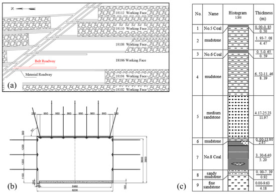
Figure 1.
(a) position of working face, (b) section of roadway facing mining, and (c) rock column diagram.
2.2. Characteristics of Coal Seam and Roof and Floor
The 18106 working face is in the No.8 coal seam. The coal seam thickness is 3.30–6.4 m, with an average of 5.20 m. The dip angle is 7.8–10.6°, with an average of 8.9°. In the upper corner of the working face and in the airflow of the working face, it is easy for gas overruns to happen due to the low permeability of the coal seam. Furthermore, using blasting operations in the working face is quite dangerous for gas explosion accidents. The immediate roof of the coal seam is mudstone with an average thickness of 2.45 m, and the underlying roof is medium sandstone with an average thickness of 11.97 m. The roof and floor of the coal seam are shown in Figure 1c. According to core test for the roof and floor coal rock, the compressive strength of the coarse-grained sandstone in the main roof is 42.9 MPa, and the tensile strength is 4.12 MPa. The structure of the coal steam is sturdy, and it is difficult to collapse even after the working face is pushed, which significantly hinders coal mine production.
3. Model Set
3.1. Model Size and Parameters
To clarify the deformation law of the facing-mining roadway influenced by working face mining, a numerical calculation model was established based on the mining geological conditions around the roadway of the 18106 working face in Xiegou Coal Mine, using 3DEC numerical simulation software. Half of the length of the working face considering its symmetry was selected for the model to simplify the model size and ensure calculation accuracy. The model size is 260 m × 200 m × 68 m (length × width × height), and horizontal constraints were applied to the model. Horizontal displacement and vertical displacement were constrained at the bottom of the model. A vertical load was applied to the top of the model according to the ground stress at a burial depth of 260 m. The gravity density is 25 kN/m3, and the applied load is 6.5 MPa. The constitutive relation of the surrounding rock block was calculated using the Mohr–Coulomb model, and the joint surface was calculated using the Coulomb sliding model.
Based on rock mechanics experiments, a reduction coefficient was determined for different weights. Simulation calibration was then carried out to obtain rock mechanic parameters that are more consistent with the actual field. The physical and mechanical parameters of each rock stratum in the model are presented in Table 1.

Table 1.
Coal and rock physical and mechanical parameters table.
3.2. Simulation Program
The numerical model is illustrated in Figure 2. The excavation of the 18104 working face starts at an x-axis coordinate of 220 m, with 5 m excavated each time, and stops when it reaches an x-axis coordinate of 40 m. In order to analyze the influence of working face mining on the facing-mining roadway, measuring points and lines were set up at the section of the material roadway 120 m along the x-axis. The deformation of the material roadway and changes in surrounding rock stress were recorded. According to the key stratum theory, the medium sandstone roof above the coal seam is the sub-key stratum that controls the movement of the overlying strata. Thus, 3DEC was used to simulate the deformation of the roadway surrounding rock under the conditions of 4 m, 6 m, 8 m, and 12 m of coarse sandstone with fracturing. Therefore, the influence of the fracturing space position on the deformation of the facing-mining roadway could be further explored. The parameter weakening method [32,33] is used for simulation. The simulation scheme is shown in Table 2, and the mechanical parameters of the rock mass in the fracturing area are shown in Table 3.
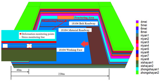
Figure 2.
Numerical model diagram.
Table 2.
Numerical simulation scheme.
Table 3.
Fracturing zone parameters.
4. Deformation Law of Surrounding Rock in the Second Stage of Facing-Mining Roadway
4.1. Stress Distribution Characteristics of Surrounding Rock in Facing-Mining Roadway
The stress distribution cloud diagram of the roadway advancing with the working face is illustrated in Figure 3. The stress distribution curve of the surrounding rock when the roadway is in front of the working face is observed in Figure 4a. When the roadway is 40 m in front of the working face, the surrounding rock of the roadway has not been affected by the advance stress of the working face. The stress on the section coal pillar is bimodal, and the peak stress is 11.15 MPa. As the working face advances towards the roadway, the section coal pillar is more and more affected by mining stress. The stress gradually changes from bimodal to unimodal, and the peak stress position gradually moves to the roadway side. When the roadway is located 10 m in front of the working face, the peak stress on the section coal pillar reaches the maximum, which is 18.44 MPa. Then, as the advance abutment pressure decreases, the peak stress on the coal pillar gradually decreases. When the roadway and the working face collide, the peak stress of the coal pillar decreases to 17.38 MPa. The stress on the solid coal gradually increases with the advance of the working face when the roadway is in front of the working face. When the roadway and the working face collide, the peak stress on the solid coal is 12.59 MPa.
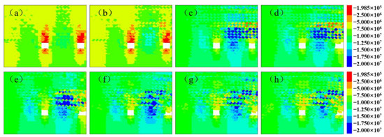
Figure 3.
The vertical stress distribution of surrounding rock in the mining roadway, when the roadway is (a) 40 m, (b) 30 m, (c) 10 m, and (d) 0 m in front of the working face, and when it is (e) 20 m, (f) 40 m, (g) 60 m, and (h) 80 m behind the working face.
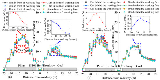
Figure 4.
Surrounding rock stress curve with the advancing of the working face when (a) the roadway is in front of the working face and (b) the roadway is behind the working face.
The stress distribution curve of the surrounding rock when the roadway is behind the working face is observed in Figure 4b. As the working face continues to move forward, the roof activity in the goaf gradually intensifies, and the peak stress on the coal pillar gradually increases. When the roadway is located 40 m behind the working face, the peak stress of the coal pillar reaches its maximum, which is 18.73 MPa. After that, with the advance in mining work, the roof activity of the goaf gradually stabilized, and the stress on the coal pillar gradually decreased. When the working face was pushed over 70 m, the peak stress decreased to 16.61 MPa. The stress change trend on the solid coal is similar to that of the coal pillar, which first increases and then decreases with the advance of the working face, and reaches the maximum (i.e., 13.13 MPa) when the working face advances to 40 m.
Overall, during the influence stage of advanced abutment pressure, with the advance of the working face, the stress on the coal pillar first increases, then decreases, and reaches its maximum when the roadway is located 0 m in front of the working face. Meanwhile, the stress on the solid coal gradually increases with the advance of the working face. In the influence stage of goaf roof activity, the stress on both the coal pillar and on the solid coal increase first, then decrease, and reach the maximum when the roadway is located 40 m behind the working face. Meanwhile, the peak stress on the coal pillar is greater than that in the influence stage with the advanced abutment pressure.
4.2. Deformation Characteristics of Surrounding Rock in Facing-Mining Roadway
The distribution cloud map of surrounding rock deformation in the facing-mining roadway along with the working face is shown in Figure 5. The deformation curve of roadway surrounding rock with the advance of the working face is depicted in Figure 6. Evidently, the deformation trend of the roadway surrounding rock is basically consistent, i.e., stable at first, then increasing, and finally returning to stability. The maximum deformation of the roadway roof is 323.6 mm, the floor is 66.0 mm, the coal pillar side is 492.8 mm, and the solid coal side is 93.6 mm. The order of deformation is as follows: coal pillar side > roof > solid coal side > floor. This indicates that the surrounding rock of the roadway has been significantly impacted by the mining of the adjacent working face. The asymmetric deformation of the coal pillar side and roof is much higher than that of the floor and solid coal side. Figure 7 illustrates the deformation velocity curve of the surrounding rock with the advance of the working face. In the influence stage of advanced abutment stress, when the roadway is 30 m away from the working face, the speed of surrounding rock deformation affected by mining stress begins to increase. When the roadway is 5 m in front of the working face, the speed of deformation reaches its maximum. After that, the mining influence weakens and there is a decrease in the deformation speed. In the influence stage of goaf activity, affected by the roof activity of the goaf, the deformation speed of the roadway gradually increases. When the roadway is 10 m behind the working face, the deformation speed reaches its maximum. Then, due to the gradual stabilization of the goaf roof, the deformation speed of the roadway gradually fluctuates and then decreases. When the roadway is located 65 m behind the working face, the deformation speed approaches 0 and the deformation of the roadway gradually stabilizes.
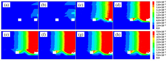
Figure 5.
Deformation distribution cloud diagram of surrounding rock in the mining roadway when the roadway is (a) 40 m, (b) 30 m, (c) 10 m, and (d) 0 m in front of the working face and when it is (e) 20 m, (f) 40 m, (g) 60 m, and (h) 80 m behind the working face.
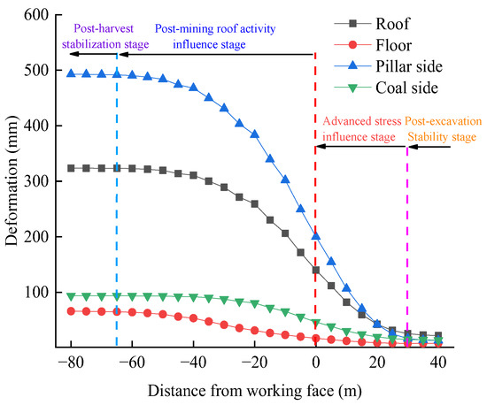
Figure 6.
Roadway surrounding rock deformation curve.
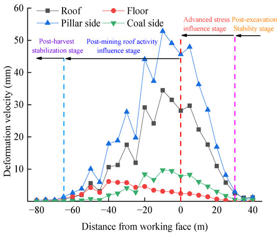
Figure 7.
Deformation velocity curve of the roadway surrounding rock.
The deformation of the facing-mining roadway in each stage is represented in Figure 8. According to Figure 8, the roof activity in the goaf is the main influencing factor on the deformation of the roadway facing mining, followed by the influence of the advance abutment pressure. The deformation in the stable stage of excavation and mining is very small and can be ignored. The curve of roadway deformation suggests that the proportion of deformation in each stage of the roof and two sides is basically the same. Specifically, (1) in the advanced stress influence stage, the proportion of deformation is 38%; (2) in the roof activity stage in goaf, the proportion of deformation is 60%; (3) in the advanced stress influence stage, the proportion of deformation of the floor is just 15%; and (4) in the goaf influence stage, the proportion of deformation reaches 82%. Accordingly, when controlling the deformation of the roadway, the influence of roof activity in the goaf should be given priority, and then the influence of advance abutment pressure should be considered.
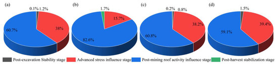
Figure 8.
Deformation ratio of each stage of roadway, (a) roof, (b) floor, (c) pillar side, and (d) coal side.
5. Reasonable Space–Time Relationship of Hydraulic Fracturing in Facing-Mining Roadway
5.1. Reasonable Time of Coal Rock Cracking Pressure Relief
According to the principle of hydraulic fracturing pressure relief [34,35] (Huang et al., 2017; Kang et al., 2020), hydraulic fracturing is used to create cracks in coal and rock masses through pore water pressure before the influence of mining stress. First, the structure of the coal and rock mass is changed, and then the coal and rock mass are further broken after the influence of mining stress. Furthermore, the propagation path of mining stress is controlled, and the bearing capacity of the carrier is weakened. Finally, the propagation mode and distribution characteristics of mining stress are changed, and the stress transfer and pressure relief are realized. Therefore, the selection of a reasonable time for hydraulic fracturing should obey the following principles.
(1) The hydraulic fracturing project must be constructed outside the influence range of the advance abutment pressure of the working face, that is,
(2) The hydraulic fracturing project must be started before the goaf roadway is affected by the mining of the working face, that is,
(3) The goaf roadway must be protected by hydraulic fracturing pressure relief before the roof of the goaf is stable, that is,
In Equations (1)–(3), vy is the fracturing speed, vg is the working face advancing speed, vh is the tunneling speed, and their units are m/d. Lc is the working face abutment pressure influence distance, Lg is the length of the deformation section of the roadway affected by mining, Lk is the distance from the working face when the roof of the goaf is stable, and L1 and L2 are the distances between the hydraulic fracturing construction site and the working face and between the hydraulic fracturing construction site and the roadway excavation face, respectively. The units of the above distance or length are m. Lastly, ΔL is the surplus coefficient, which is generally from 3 m to 5 m, and t (which is measured in d) is the construction time of hydraulic fracturing.
According to the movement law of overlying strata obtained through numerical simulation, the distance of influence of the advanced abutment pressure on the 18104 working face in Xiegou Mine is 30 m. The length of the deformation section of the material roadway affected by mining in the 18106 working face is 20 m, and the length of the roof activity section of the gob is 65 m. According to the production data of the Xiegou Coal Mine, the advancing speed of the working face is 5 m/d, and the tunneling speed of the roadway is 8 m/d. Because the fracturing site is located in the belt roadway, and in consideration of production and construction safety at the working face, the hydraulic fracturing construction speed is calculated based on the daily construction of only two holes per maintenance cycle. The construction speed is 14 m/d, and the surplus coefficient is 5 m. Substitute the above data into Equations (1)–(3) to obtain:
Therefore, the reasonable construction time for hydraulic fracturing is visualized in Figure 9. The hydraulic fracturing project must start before the distance between the working face and the roadway is 187 m. The distance between the starting point of the hydraulic fracturing construction and the working face should be greater than 35 m, and the distance from the roadway should be greater than 152 m. The condition L2 > 96 + 1.6 L1 should be satisfied. Thus, considering the construction speed, the equipment installation in the early stage of hydraulic fracturing, and the time required for the construction of materials and fracturing boreholes, hydraulic fracturing should be started at a reasonable position at least 17 days before the intersection of the working face and the roadway.
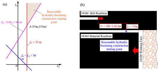
Figure 9.
Reasonable time of hydraulic fracturing with (a) construction starting point value range and (b) reasonable construction starting position diagram.
5.2. Reasonable Space Position of Coal Rock Cracking Pressure Relief
Figure 10 illustrates the deformation curve of the roadway with the working face under different fracturing heights, and Figure 11 illustrates the deformation cloud diagram. The roadway deformation is stable, deformed, and then stable with the advance of the working face. Moreover, the roadway deformation in the advanced stress influence stage and the goaf activity influence stage is consistent with the change trend of the fracturing height, and the deformation decreases with the increase in the fracturing height. The trend of deformation in the roof and the two sides is basically the same, i.e., the roadway deformation decreases gradually with the increase in fracturing height, but the decrease in the roadway deformation reduces with the increase in fracturing height. The changing trend of floor deformation is approximately a straight line. When the fracturing height increases to 10 m, the influence of fracturing height on the roof and two sides of the roadway is no longer significant. Concurrently, the roadway deformation is 54.8 mm (roof), 38.1 mm (floor), 86 mm (coal pillar side), and 9.6 mm (solid coal side), and the reduction is 83.1%, 42%, 82.5%, and 89.7%, respectively.
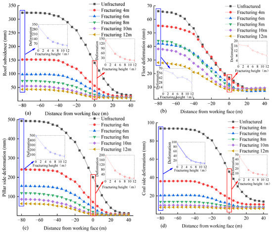
Figure 10.
Deformation of the roadway advancing with the working face under different fracturing heights of the (a) roof, (b) floor, (c) pillar side, and (d) coal side.
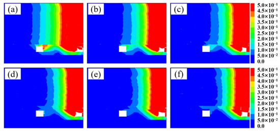
Figure 11.
Deformation nephogram of the roadway surrounding rock under different fracturing heights, including (a) unfractured, (b) 4 m, (c) 6 m, (d) 8 m, (e) 10 m, and (f) 12 m fracturing.
In summary, hydraulic fracturing mainly controls roadway deformation in the advanced stress influence stage and the goaf roof activity stage. The specific influence mechanism is that the hydraulic fracturing roof has an obvious effect on reducing the roadway deformation, and the effect on the roadway deformation is no longer obvious when the fracturing height reaches 10 m. Therefore, the reasonable height of hydraulic fracturing is 10 m.
6. Engineering Practice
6.1. Construction Scheme
According to the research results, the 18104 material roadway 40 m in front of the working face was selected as the starting point of the engineering practice. Hence, the distance from the heading roadway working face is 160 m, and the hydraulic fracturing test range is 100 m. The arrangement of hydraulic pre-splitting boreholes in hard roof is shown in Figure 12. In order to ensure full fracturing, increase the damaged area of fracturing, and promote the penetration of cracks, drilling was carried out in the 18104 material roadway. The drilling was arranged in a single row with a perpendicular angle to the roadway roof. The drilling depth is 13.85 m with a spacing of 7 m. The hole is opened on the side of the roof coal pillar at a position of 300~500 mm away from the roadway side, and the drilling diameter is 42 mm. The anchor cable drilling and the supporting small aperture packer were used for staged fracturing. To increase the number of cracks in the hydraulic fracturing process and ensure pressure relief, a pump with a displacement of 200 L/min was adopted for fracturing. According to the tensile strength and buried depth of the medium sandstone roof, the fracturing water pressure was determined as 40 MPa.
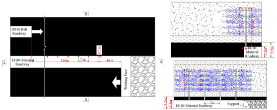
Figure 12.
Hydraulic fracturing borehole layout of the hard roof.
6.2. Control Effect
6.2.1. Hydraulic Fracturing Performance
Through observation of the fracturing borehole via the borehole peep, we found that there were obvious cracks along the axial direction of the borehole wall influenced by the high-pressure water, and obvious circumferential cracks appeared at the sectional fracturing. The two kinds of cracks were incorporated to an effective fracture zone, as shown in Figure 13. With the retreat of the packer during the implementation of the fracturing site, the distance between the fracturing position and the orifice was gradually reduced, and the water injection pressure required for hydraulic fracturing also decreased. During hydraulic fracturing, the range of water spray around the borehole continuously expanded, and the time required for water spray continuously decreased. Such phenomenon indicates that the water pressure has formed a penetrating fracture around the borehole.
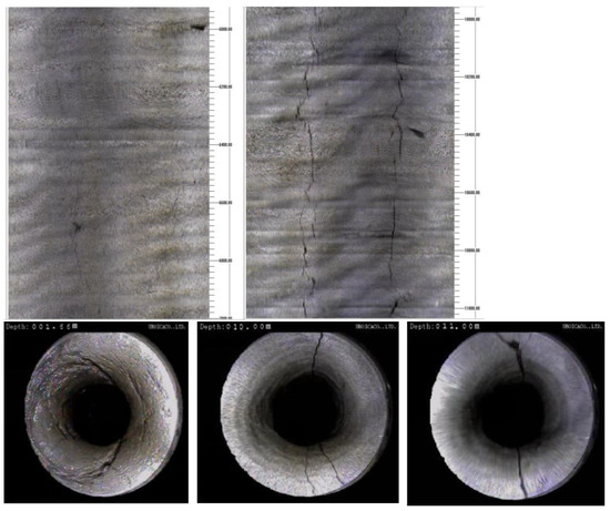
Figure 13.
Fracturing borehole.
6.2.2. Control Effect of Roadway Surrounding Rock
The main purpose of the hydraulic fracturing pressure relief test in the Xiegou Coal Mine is to reduce the influence of adjacent working face mining on the facing-mining roadway, to control the deformation, as well as to ensure the safe production and normal replacement of the coal mine. The monitoring results of roadway surface displacement are the cornerstones for judging the pressure relief effect of hydraulic fracturing. The data recorded by the surface displacement station of the roadway in the hydraulic fracturing test section of the 18106 belt roadway and the surface displacement station of the 18106 material roadway under similar conditions were collected. Hence, the deformation curve of the surrounding rock of the 18106 belt roadway influenced by the mining of the 18104 working face is shown in Figure 14.
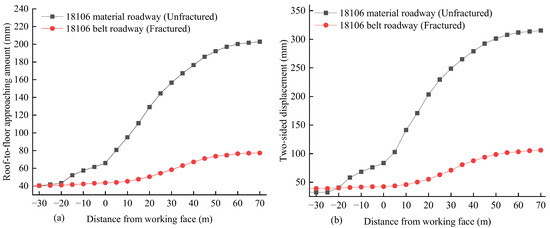
Figure 14.
The deformation of the mining roadway. (a) The roof and floor convergence and (b) the two sides convergence.
From Figure 14, the deformation of the roadway surrounding rock measured on site is not much different from that of the numerical simulation, and the deformation trend of the roadway surrounding rock is basically the same, which verifies the accuracy of numerical simulation results. During the period unaffected by the adjacent working face, the roadway deformation in the fractured section is basically the same as the unfractured section. However, under the influence of the adjacent working face mining, the deformation of the surrounding rock in the unfractured section is significantly higher than that in the fractured section. The deformation in the fractured section gradually stabilizes after the working face is pushed over 50 m, while the deformation in the unfractured section gradually stabilizes after the working face is pushed over 60 m. The maximum displacement of the roof and floor in the fracturing section is 78 mm, which is 62.5% lower than the 203 mm in the unfractured section. The maximum displacement of the two sides is 107 mm, which is 66.1% lower than the 316 mm in the unfractured section. The deformation of the surrounding rock after fracturing has been effectively controlled. This indicates that hydraulic fracturing has a positive effect on controlling surrounding rock deformation in facing-mining roadway.
7. Conclusions
(1) The surrounding rock stress on the coal pillar side of the roadway increases first and then decreases in the advanced stress influence stage and the goaf roof activity influence stage of mining. The surrounding rock stress on the solid coal displays a monotonous increasing trend in the influence stage of advance stress and increases first and then decreases in the active stage of goaf roof.
(2) The surrounding rock of the facing-mining roadway shows obvious asymmetric deformation under the influence of adjacent mining operations, and the order of deformation is coal pillar > roof > solid coal > floor. The influence of goaf roof activity is the most important factor in roadway deformation (accounting for 60%), and the influence of advanced stress is also a main factor (accounting for 38%).
(3) The principle for determining the reasonable construction time of hydraulic fracturing is proposed. The reasonable construction time for fracturing is determined to be 17 days before the intersection of the working face and the roadway. The distance, L1, from the starting point of construction to the working face should be greater than 35 m, the distance, L2, from the roadway should be greater than 152 m, and the condition L2 > 96 + 1.6 L1 should be satisfied simultaneously.
(4) The surrounding rock deformation of the roadway gradually decreases with the increase in fracturing height in both stages. The decrease in deformation of the two sides and roof of the roadway follows a straight line. When the fracturing height reaches 10 m, the reduction in roadway deformation is no longer significant. Therefore, the reasonable fracturing height is determined to be 10 m.
Author Contributions
Conceptualization, X.Y. and C.L.; Methodology, X.Y. and C.L.; Software, X.Y. and H.L.; Formal analysis, H.L.; Investigation, C.L., J.B. and H.Z.; Resources, C.L., H.Z. and H.L.; Data curation, J.B.; Writing—original draft, X.Y.; Writing—review & editing, X.Y. and C.L.; Visualization, X.Y. and H.Z.; Supervision, J.B.; Project administration, J.B.; Funding acquisition, C.L. All authors have read and agreed to the published version of the manuscript.
Funding
This research was funded by National Natural Science Foundation of China (grant number 52074267).
Data Availability Statement
Data are available on request to the authors.
Acknowledgments
The authors gratefully acknowledge the financial support of the agencies mentioned above.
Conflicts of Interest
The authors declare no conflict of interest.
References
- Xue, J.; Ma, Q.; Du, X.; Zhan, K.; Sun, B. Numerical simulation and control of a rockburst induced by main roof fracture in a deep coal seam. Energy Sources Part A Recovery Util. Environ. Eff. 2020, 1–17. [Google Scholar] [CrossRef]
- Li, G.; Wang, X.; Bai, J.; Wu, B.; Wu, W. Research on the failure mechanism and control technology of surrounding rock in gob-side entry driving under unstable overlying strata. Eng. Fail. Anal. 2022, 138, 106361. [Google Scholar] [CrossRef]
- Kan, J.; Dou, L.; Li, X.; Li, J.; Chai, Y. Investigating the destressing mechanism of roof deep-hole blasting for mitigating rock bursts in underground coal mines. Geomat. Nat. Hazards Risk 2022, 13, 2508–2534. [Google Scholar] [CrossRef]
- Wang, Q.; Jiang, B.; Xu, S.; He, M.; Jiang, Z.; Li, S.; Wei, H.; Xiao, Y. Roof-cutting and energy-absorbing method for dynamic disaster control in deep coal mine. Int. J. Rock Mech. Min. Sci. 2022, 158, 105186. [Google Scholar] [CrossRef]
- Yang, H.; Wang, D.; Ju, W.; Yuan, W.; Su, C. Asymmetric Damage Mechanisms and Prevention Technology in Large-Section Gob-Side Entry Retaining. Sustainability 2023, 15, 739. [Google Scholar] [CrossRef]
- Kan, J.; Dou, L.; Li, X.; Li, J.; Bai, J.; Cao, J.; Liu, M. Effect of initiation pattern on rock damage and blasting seismic under multi-hole blasting. Geomat. Nat. Hazards Risk 2023, 14, 2192334. [Google Scholar] [CrossRef]
- Zhang, G.; Lu, H.; Zhao, W. Branch fractures in oriented hydraulic fracturing, modeling, and experiments. Energy Sources Part A Recovery Util. Environ. Eff. 2014, 36, 563–573. [Google Scholar] [CrossRef]
- Shao, L.; Huang, B.; Zhao, X.; Xing, Y. Criteria for the progressive initiation and propagation of radial and axial fractures of borehole during rock hydraulic fracturing. Energy Sources Part A Recovery Util. Environ. Eff. 2020, 1–17. [Google Scholar] [CrossRef]
- Liu, Y.; Yang, X.; Guo, J.; Wang, S.; Zhao, Z. Optimization method of fracture parameters in multistage fracturing of horizontal wells. Energy Sources Part A Recovery Util. Environ. Eff. 2021, 1–19. [Google Scholar] [CrossRef]
- He, T.; Huang, Z.; Li, C.; Luo, F.; Wang, D. Temporal and spatial evolution characteristics of lateral coal stress in fully mechanized top coal caving mining working face in ultra-thick coal seam. J. Min. Saf. Eng. 2018, 35, 100–105. (In Chinese) [Google Scholar] [CrossRef]
- Dou, L.; He, H. Study of OX-F-T spatial structure evolution of overlying strata in coal mines. Chin. J. Rock Mech. Eng. 2012, 31, 454–460. (In Chinese) [Google Scholar]
- Qi, W.; Zhang, Q.; Zhang, J.; Zhang, J.; Zhu, C. Design of coal pillars of gob-side entry between mining faces with large differences in mining height in deep mine. Energy Sources Part A Recovery Util. Environ. Eff. 2020, 42, 2648–2663. [Google Scholar] [CrossRef]
- Liu, H.; Liu, C.; Dong, Y. Theoretical Study on the Mechanism of Asymmetrical Large Deformation of Heading Roadway Facing Mining. Sustainability 2022, 14, 15065. [Google Scholar] [CrossRef]
- Ma, N.; Zhang, W.; Li, J.; Lian, X.; Ren, J. Analysis and evaluation of essential factors for rock burst mechanism. J. Min. Sci. Technol. 2021, 6, 651–658. (In Chinese) [Google Scholar] [CrossRef]
- Xu, X.; He, F.; Li, X.; He, W. Research on mechanism and control of asymmetric deformation of gob side coal roadway with fully mechanized caving mining. Eng. Fail. Anal. 2021, 120, 105097. [Google Scholar] [CrossRef]
- Li, G.; Ma, F.; Guo, J.; Zhao, H. Experimental research on deformation failure process of roadway tunnel in fractured rock mass induced by mining excavation. Environ. Earth Sci. 2022, 81, 243. [Google Scholar] [CrossRef]
- Wu, P.; Liang, B.; Jin, J.; Li, G.; Wang, B.; Guo, B.; Yang, Z. Research of roadway deformation induced by mining disturbances and the use of subsection control technology. Energy Sci. Eng. 2022, 10, 1030–1042. [Google Scholar] [CrossRef]
- Wang, D.; He, F.; Wu, Y.; Xu, X.; Zhang, J.; Lv, K.; Li, L.; Zhai, W.; Song, J. Study on surrounding rock failure mechanism and rational coal pillar width of the gob-side coal roadway under influence of intense dynamic pressure. Energy Sci. Eng. 2023, 11, 1716–1733. [Google Scholar] [CrossRef]
- Han, C.; Yang, H.; Zhang, N.; Deng, R.; Guo, Y. Zoning Control Technology of Gob-Side Roadway Driving with Small Coal Pillar Facing Mining in a Special Isolated Island Working Face: A Case Study. Appl. Sci. 2021, 11, 10744. [Google Scholar] [CrossRef]
- He, Q.; Zhu, L.; Li, Y.; Zhang, B. Simulating Hydraulic Fracture Re-orientation in Heterogeneous Rocks with an Improved Discrete Element Method. Rock Mech. Rock Eng. 2021, 54, 2859–2879. [Google Scholar] [CrossRef]
- Li, H.; Bai, H.; Ma, L.; Kang, Z.; Li, Z.; Miao, X.; Wu, P.; Wei, J. Research on the Evolution Law of Water Flowing Fractures in the Jurassic and Carboniferous Coal Seams Based on FDEM Simulation. J. China Coal Soc. 2022, 47, 4443–4454. (In Chinese) [Google Scholar] [CrossRef]
- Heider, Y.; Markert, B. A phase-field modeling approach of hydraulic fracture in saturated porous media. Mech. Res. Commun. 2017, 80, 38–46. [Google Scholar] [CrossRef]
- Sarmadi, N.; Nezhad, M.M. Phase-field modelling of fluid driven fracture propagation in poroelastic materials considering the impact of inertial flow within the fractures. Int. J. Rock Mech. Min. Sci. 2023, 169, 105444. [Google Scholar] [CrossRef]
- Chen, Z.; Li, X.; Dusseault, M.B.; Weng, L. Effect of excavation stress condition on hydraulic fracture behaviour. Eng. Fract. Mech. 2020, 226, 106871. [Google Scholar] [CrossRef]
- Lu, Y.; Gong, T.; Xia, B.; Yu, B.; Huang, F. Target stratum determination of surface hydraulic fracturing for forefield hard roof control in underground extra-thick coal extraction: A case study. Rock Mech. Rock Eng. 2019, 52, 2725–2740. [Google Scholar] [CrossRef]
- Liu, J.; Liu, C.; Li, X. Determination of fracture location of double-sided directional fracturing pressure relief for hard roof of large upper goaf-side coal pillars. Energy Explor. Exploit. 2019, 38, 111–136. [Google Scholar] [CrossRef]
- Liu, J.; Liu, C.; Yao, Q.; Si, G. The position of hydraulic fracturing to initiate vertical fractures in hard hanging roof for stress relief. Int. J. Rock Mech. Min. Sci. 2020, 132, 104328. [Google Scholar] [CrossRef]
- Lekontsev, Y.M.; Sazhin, P.V. Application of the directional hydraulic fracturing at Berezovskaya Mine. J. Min. Sci. 2008, 44, 253–258. [Google Scholar] [CrossRef]
- Huang, B.; Chen, S.; Zhao, X. Hydraulic fracturing stress transfer methods to control the strong strata behaviours in gob-side gateroads of longwall mines. Arab. J. Geosci. 2017, 10, 236. [Google Scholar] [CrossRef]
- Huang, B.; Zhao, X.; Ma, J.; Sun, T. Field experiment of destress hydraulic fracturing for controlling the large deformation of the dynamic pressure entry heading adjacent to the advancing longwall face. Arch. Min. Sci. 2019, 64, 829–848. [Google Scholar] [CrossRef]
- Li, C.; Xin, D.; Liu, Y.; Chen, T. A Case Study on Strong Strata Behaviors Mechanism of Mining Reserved Roadway and Its Prevention Techniques. Processes 2023, 11, 1341. [Google Scholar] [CrossRef]
- Liu, J. Research on Mechanism and Control of Stress Field Change of Artificial Cracking Coal and Rock Mass. Ph.D. Thesis, China University of Mining & Technology, Xuzhou, China, 2020. [Google Scholar] [CrossRef]
- Zhang, H. Study on Hydraulic Fracturing Pressure Relief Control in Pre-Excavated Retreat Way of Fully Mechanized Coal Mining Face. Master’s Thesis, China University of Mining & Technology, Xuzhou, China, 2022. [Google Scholar] [CrossRef]
- Huang, B.; Zhao, X.; Chen, S.; Liu, J. Theory and technology of controlling hard roof with hydraulic fracturing in underground mining. Chin. J. Rock Mech. Eng. 2017, 36, 2954–2970. [Google Scholar] [CrossRef]
- Kang, H.; Jiang, P.; Huang, B.; Guan, X.; Wang, Z.; Wu, Y.; Gao, F.; Yang, J.; Cheng, L.; Zheng, Y.; et al. Roadway strata control technology by means of bolting-modification-destressing in synergy in 1000 m deep coal mines. J. China Coal Soc. 2020, 45, 845–864. [Google Scholar] [CrossRef]
Disclaimer/Publisher’s Note: The statements, opinions and data contained in all publications are solely those of the individual author(s) and contributor(s) and not of MDPI and/or the editor(s). MDPI and/or the editor(s) disclaim responsibility for any injury to people or property resulting from any ideas, methods, instructions or products referred to in the content. |
© 2023 by the authors. Licensee MDPI, Basel, Switzerland. This article is an open access article distributed under the terms and conditions of the Creative Commons Attribution (CC BY) license (https://creativecommons.org/licenses/by/4.0/).