Article

Sludge Reduction and Surface Investigation in Electrochemical Machining by Complexing and Reducing Agents

by
Gustavo Cercal
1,2,
Gabriela de Alvarenga
1 and
Marcio Vidotti
1,*
1
Grupo de Pesquisa em Macromoléculas e Interfaces, Departamento de Química, Universidade Federal do Paraná, CP 19064, Curitiba 81531-980, PR, Brazil
2
Processes Development Engineering, Powertrain Solutions, Robert Bosch Ltda, Av. Juscelino K Oliveira, 11800, Curitiba 81020-490, PR, Brazil
*
Author to whom correspondence should be addressed.
Processes 2023, 11(7), 2186; https://doi.org/10.3390/pr11072186
Submission received: 6 June 2023 / Revised: 11 July 2023 / Accepted: 18 July 2023 / Published: 21 July 2023

Abstract

:
Electrochemical machining (ECM) is widely applied to manufacture parts with complex geometries, used in electronic components and the automotive, military, and aeronautics industries. These parts have a surface shaped by controlled anodic dissolution at high current density levels, using a neutral solution of inorganic salts (i.e., NaCl or NaNO3) as the electrolyte. Such conditions generate a high amount of sludge that deposits onto the surfaces of equipment, devices, cathodes, and working pieces, requiring daily and complicated sludge management during the series production in the industry. Thus, the main goal of the present work is to propose a simple way to reduce sludge generation in the ECM industrial process. To do so, complexing (EDTA) or reducing (ascorbic acid) agents were added to the electrolyte composition, creating parallel reactions to keep the metallic ions from precipitating. The complexing agent EDTA resulted in a 30% reduction in sludge mass, using an alkaline solution (pH > 10.0). The reducing agent, ascorbic acid, resulted in a 90% reduction in sludge mass, using an acidic solution (pH < 5.0). This sludge reduction has the potential to contribute significantly to increasing equipment, devices, and cathode lifetime, as well as reducing costs associated with centrifuge or filter maintenance (sludge removal from electrolyte) and increasing the productivity of industrial ECM processes.

1. Introduction

Electrochemical machining (ECM) is an effective and well-established technology for shaping complex machinery pieces [1] and for microfabrication [2,3], using different substrates such as titanium [4], copper [5] nickel alloys [6,7], stainless steel [8,9], and refractory materials [10]. Another advantage of ECM is the absence of any residual stress, plastic deformation, fatigue, or burrs, and the low roughness of the surface, due to the absence of physical contact between the workpiece and the ECM electrode [10,11,12,13]. These characteristics are key factors in the wide application of this technology in different sectors, such as the automotive, aeronautics, and military industries, and microelectronic component fabrication.
The ECM process is based on the anodic dissolution of a metallic workpiece, where the workpiece acts as the anode of a two-electrode electrochemical cell. A counter-electrode is used as a cathode and a constant flow of an electrolytic solution passes through it. A high voltage is applied between the electrodes, and the dissolution is observed by the formation of a current. The shape of the counter-electrode determines the geometric configuration and the interfacial morphology of the workpiece. Other experimental parameters such as the chemical composition of the electrolyte, processing time, and applied potential also contribute to the final features of the workpiece.
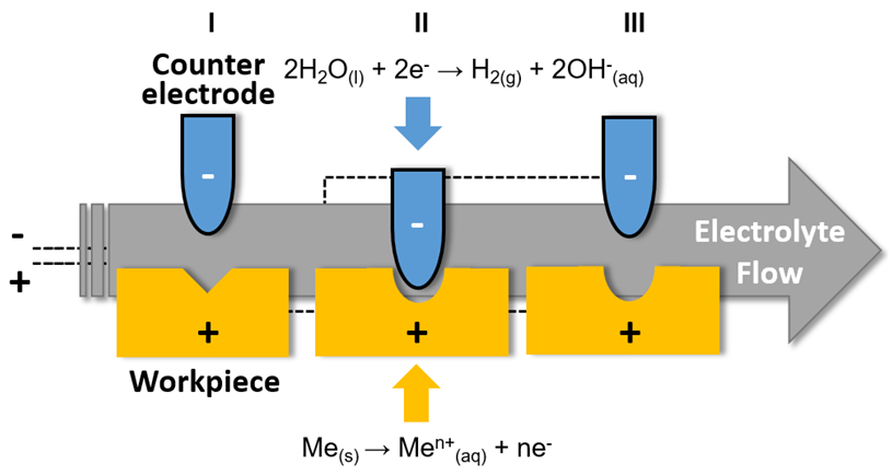
Fast and direct fabrication is very important in industry, so large current densities (about 10~100 A cm−2), high speed and pressure of the electrolyte (about 5~50 m s−1 and 1~20 bar, NaCl or NaNO3 aqueous solution), and gap control between the electrodes (0.5 ~1.5 mm) are normally employed to achieve the desirable geometry and roughness of the final workpiece [12,13,14,15]. The overall process and the redox reactions are presented in Appendix A. The overall redox reaction results in the formation of metal hydroxides and/or oxyhydroxides, as established in the following reactions:
M e s + n H 2 O l n H 2 g + M e ( O H ) n ( s )
M e s + n H 2 O l n H 2 g + M e n O m x H 2 O ( s )
On an industrial scale, the generation of solid oxyhydroxides in the electrolyte results in several operational difficulties, such as interruptions of production for maintenance, the frequent need to replace machine components and electrolytes, constant cleaning of the reaction chamber, high rates of equipment corrosion, and daily removal of solid waste using external machinery, drastically reducing the effectiveness of the process as a whole and having an enormous negative effect on productivity [12,13]. Furthermore, the complex composition of the solid waste also requires appropriate treatment and disposal, including physical–chemical pre-treatments such as coagulation and precipitation, followed by incineration, as well as expensive handling of heavy metals [16,17]. In some cases, the sludge can be reused as building materials and catalysts or recovered by pyrometallurgy and hydrometallurgy [16,17], but this is not common for most of the sludge generated in the ECM industry, and simpler and more cost-effective alternatives are still necessary. Alternatives to reduce this solid waste generation in ECM could minimize daily production difficulties while improving productivity and waste management [18].
To this end, the use of complexing and reducing agents in ECM electrolyte compositions is an interesting alternative. Such substances can reduce the metal oxyhydroxide precipitation level due to competitive reactions with the metal anodic dissolution. EDTA forms a metal complex with great stability due to the hexadentate ligand property, as is well known in the literature [19,20], and iron is the major component of SAE 4144M steel, representing more than 95% of the steel. Its application in an electrolyte solution creates parallel complexing reactions with the metallic ions dissolved. Along with EDTA, ascorbic acid has a huge reducing capacity due to its easy oxidation to deidroascorbic acid in aqueous media. Thus, its use in ECM electrolyte solutions could reduce metal ion valence and consequently increase metal ion solubility, avoiding precipitation [21,22]. The iron valence reduction from Fe3+ to Fe2+ reduces the formation of a precipitate, since Fe2+ has significantly higher solubility in aqueous media. Both substances show large availability and no operational restrictions for industrial environment applications, reasons why the use of these substances is considered an interesting strategy to avoid heavy metal oxyhydroxide precipitation in the ECM process. The workpiece material tested in this study was SAE 4144M steel, used in a diesel fuel injection pump from Robert Bosch Ltda. The material was forged, quenched, and tempered, leading to a final hardness of 39 ± 3 HRC, and pre-machined before the ECM industrial process.
The novelty of this work is the great potential for significant sludge reduction by using complexing or reducing agents in a practical application of the ECM industrial process. EDTA’s complex-formation mechanisms and ascorbic acid’s reducing mechanisms are well known in the literature, but their use as additives in an anodic dissolution reaction (which occurs in the ECM process) is reported here for the first time. The proposed addition of these substances in the conventional ECM electrolyte (aqueous solution containing an inorganic salt, commonly NaCl or NaNO3) can also contribute to the overall ECM industrial process efficiency and improve the process sustainability by decreasing the volume of solid residue treatment required.

2. Materials and Methods

2.1. Tests Procedure

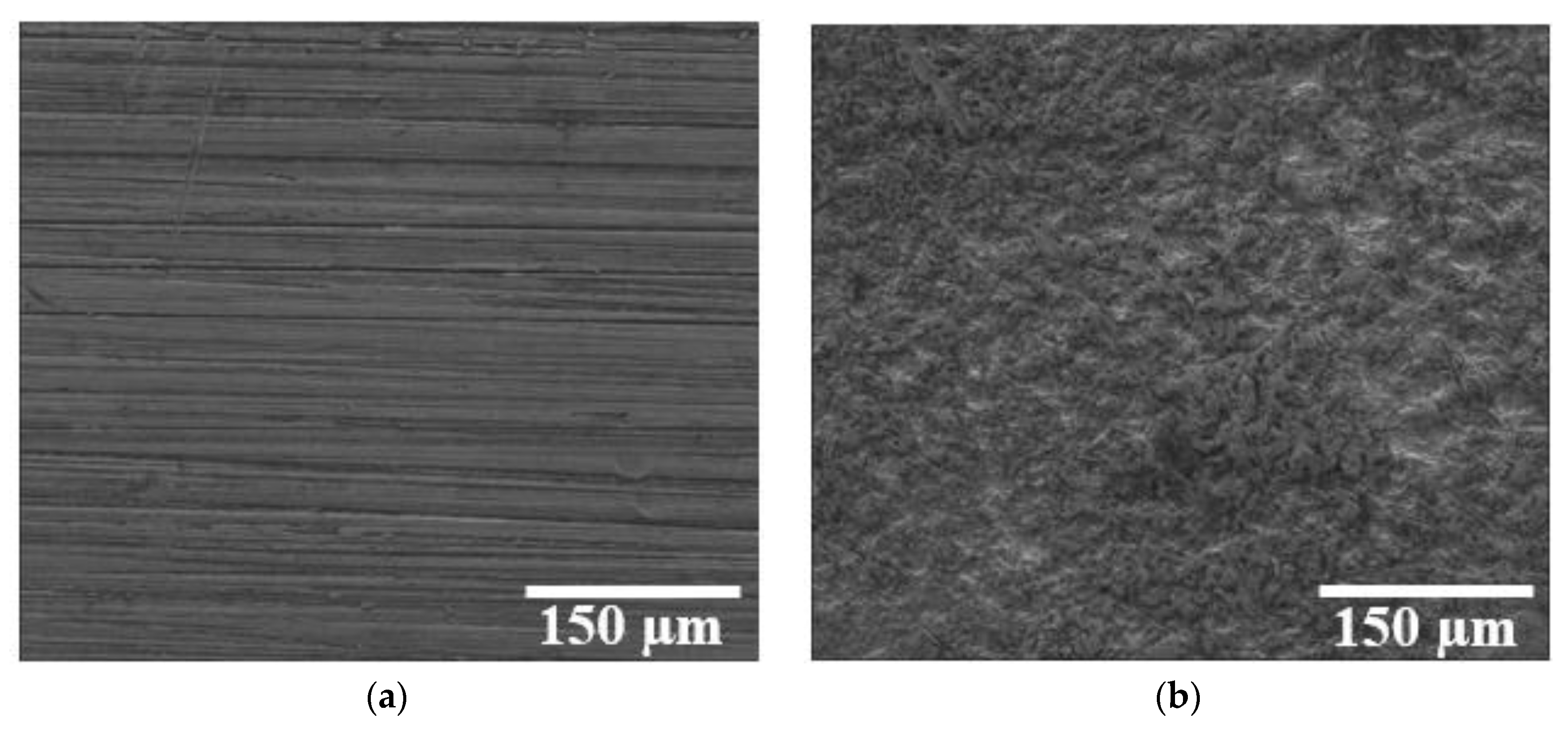
A scale-down of the industrial ECM process was necessary so that experiments could be conducted in the laboratory. Figure 1a shows the main components of the anodic dissolution cell used in this work. The counter-electrode employed has the same material as the industrial one, and the workpiece was replaced by an SAE 4144M rectangular steel piece with fixed dimensions of 10.0 ± 1.0 mm × 20.0 ± 1.0 mm × 5.0 ± 1.0 mm. A geometrical area of 1.0 cm2 was delimited by a synthetic enamel film. The workpiece has a smooth surface (roughness Ra < 0.5 µm and Rz < 2.0 µm) measured by the Mahr Perthometer Concept (PKR), and it was ensured that the ECM process did not have any significant effect on the morphology of the electrodes, as verified by the SEM images before (Figure 2a) and after (Figure 2b) the ECM process.
The optimized experimental parameters of the ECM used in the experiments are presented in Table 1. In summary, a voltage of 5 V was applied for 180 s. Each experiment was performed in triplicate, and the average and standard deviation for each parameter were considered for comparison. The standard electrolyte employed was a 100 g L−1 NaCl solution. The standard solution was modified by adding four concentrations of the complexing agent, EDTA tetrassodium: 5.0, 15.0, 25.0, and 35 g L−1. The standard electrolyte was also modified by three concentrations of the reducing agent, ascorbic acid (Fluka): 10.0, 20.0, and 30.0 g L−1.

2.2. Characterization

After the workpiece anodic processing and sludge formation (Figure 1b), the electrodes were removed, and the liquid medium containing the generated sludge was centrifuged (Spinlab SL-5M-PLATE, São Paulo, Brazil) using falcon polypropylene tubes for 30 min at 4500 rpm, and the supernatant electrolyte was removed. The wet sludge was submitted to air drying (Sterilifer Model SX 1.3 DTME, São Paulo, Brazil) for 48 h at 90 °C and the final mass was verified.
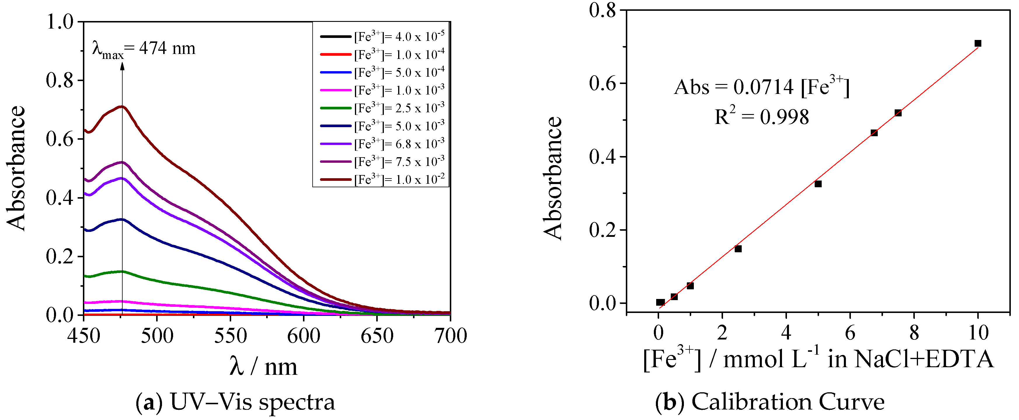
The removed electrolyte was submitted to pH and conductivity analysis and UV–Vis spectroscopy (Agilent Cary 60, Santa Clara, CA, USA) to determine the ionic iron species concentration in the electrolyte. For the calibration curves, the Fe2+ source was FeSO4·7H2O and the Fe3+ source was FeCl3. In the case of the standard electrolyte with EDTA addition, the calibration curves were made using the absorbance at 474 nm and the combination of 100 g L−1 of NaCl with 15 g L−1 of EDTA (Figure A1—Fe2+ and Figure A2—Fe3+) [19,23]. The Fe3+ calibration curves gave better adjustments, so to evaluate all the electrolytes generated, they were previously treated with H2O2 to ensure that the possible remaining Fe2+ ions were converted to Fe3+. Then, all the iron determination was performed with the Fe3+ calibration curves (Figure A2—Fe3+).
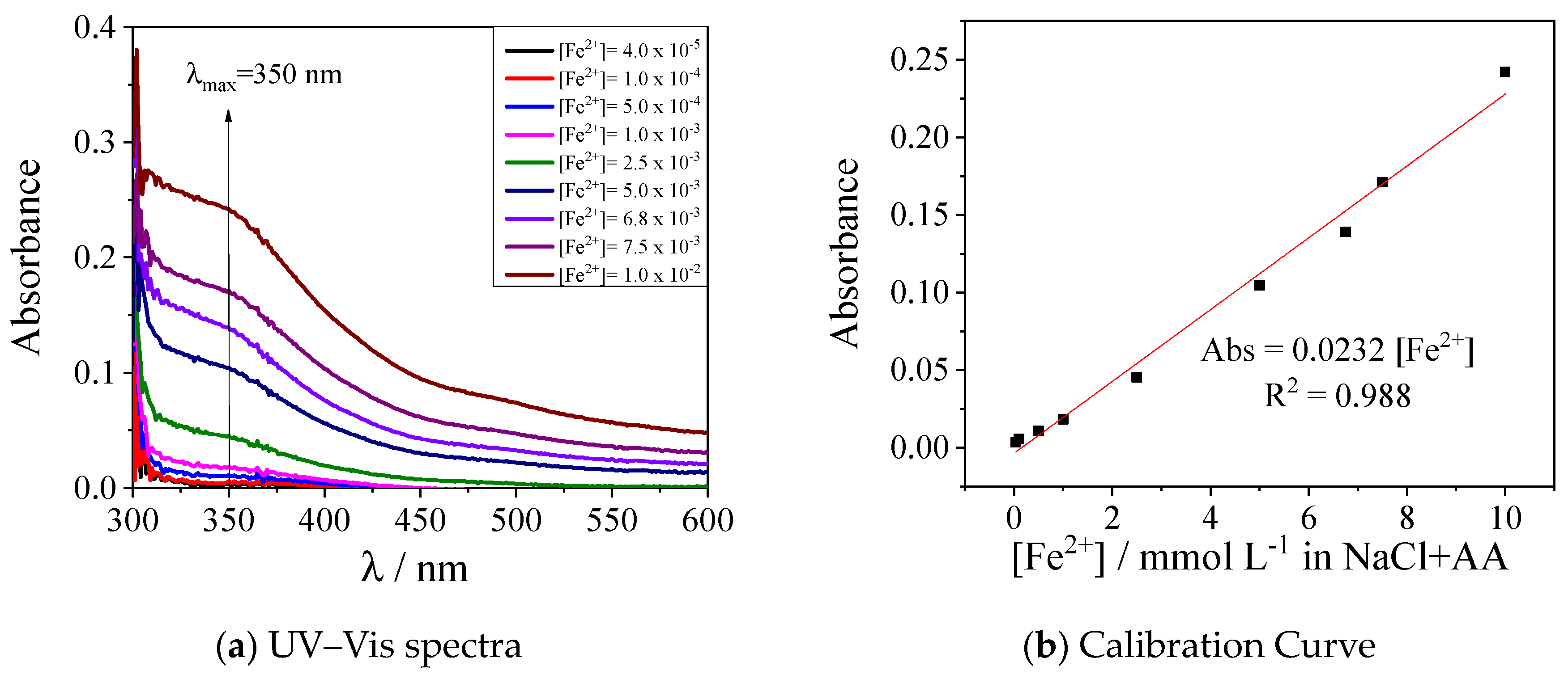
In the case of the standard electrolyte with the addition of ascorbic acid, the calibration curves were made using the absorbance at 350 nm and the combination of 100 g L−1 of NaCl with 20 g L−1 of ascorbic acid. Both curves (Figure A3—Fe2+ and Figure A4—Fe3+) presented very similar behavior and adjustments [21,22]. As ascorbic acid is an excellent reducing agent, possibly all remaining Fe3+ ions were converted to Fe2+. Based on this ascorbic acid property, the iron determination was performed with the Fe2+ calibration curves (Figure A3—Fe2+) for this electrolyte’s configuration.
The dried sludge was characterized by FTIR (Bomen Hartman, with a resolution of 4 cm−1), using KBr pellets. Finally, the workpiece surface was characterized by scanning electron microscopy and energy-dispersive X-ray spectroscopy (FEI Quanta 200, Hillsboro, OR, USA), with a minimum of five different points of each sample to verify the reproducibility and reliability of the anodic dissolution procedure.
The anodic dissolution rate (ADR) was obtained by the mass difference of the workpiece, using Equation (1) and considering the electrochemical machining time and SAE 4144M steel density ( ρ S A E 4144 M = 7.87 g cm−3) [24]:
A D R m m 3 m i n = ( m i n i t i a l m f i n a l ) ρ a l l o y × t p r o c e s s  

3. Results and Discussion

Figure 1 shows a scheme of the experimental setup for the scaled-down process. During the process, macroscopic changes are visible, especially sludge formation. The sludge has a dark brown color, and besides forming in the electrolyte, it also adheres to the workpiece and the counter-electrode surfaces. These macroscopic aspects were observed in all experiments and demonstrate how this residue can adsorb onto any part of the machinery used in industrial production. The sludge formation requires that all ECM industrial processes stop at least three times in a workday (one stop every 8 work hours) for electrode replacement and cleaning of the adsorbed residue. Naturally, these interruptions result in a huge productivity loss, corresponding to about 10% of the equipment’s idle time (i.e., ECM industrial process of Robert Bosch Ltda).
Sodium chloride (NaCl) was used as a reference electrolyte (100 g L−1), as normally used in industrial ECM processes. In the laboratory-scale setup, 232 ± 33 mg of sludge was generated after the anodic dissolution procedure and the pH of the electrolyte increased from 6.5 ± 0.1 to 10.6 ± 0.1. The pH increases mainly due to hydroxyl generation in the counter-electrode from water electrolysis and pH determination improves the understanding of what this behavior would be when complexing or reducing agents are added to the electrolyte. The workpiece mass loss was 67 ± 15 mg and the removal rate was 2.9 ± 0.5 mm3 min−1. Figure 2 shows the morphology of the workpiece before (a) and after (b) the anodic dissolution. An increase in surface roughness after the process can be seen due to material removal from the workpiece surface. These results were considered a valid reproduction of the industrial process and were used as a reference for comparison with other electrolyte compositions.
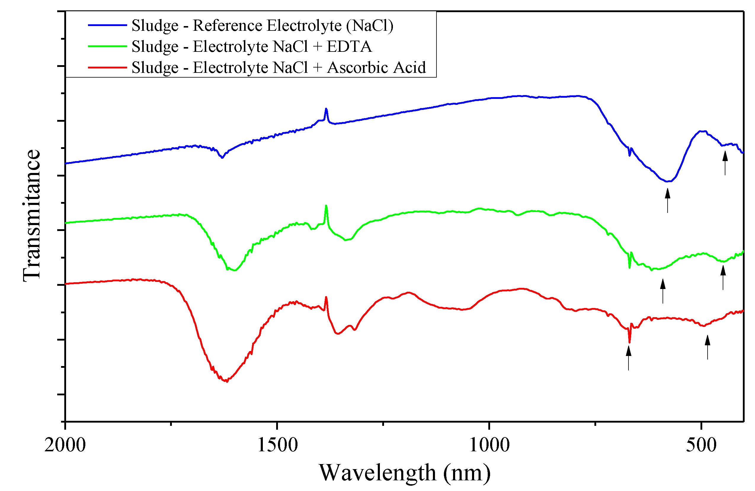
The sludge was characterized by FTIR spectroscopy, and in general, the presence of a mixture of different iron oxyhydroxides was verified (Figure A5). The characteristic peak around 580–600 cm−1 suggests the presence of hematite [α-Fe2O3], and the peak around 450 cm−1 could be attributed to a small amount of goethite [FeO(OH)] [25,26].

3.1. Complexing Agent Presence on Electrolyte Composition

Due to the formation of strong and highly stable metal–EDTA complexes, as shown in Figure 3e, this complexing agent was used in the electrolyte to create a competitive reaction, avoiding oxyhydroxide formation by the generation of strong iron–EDTA complexes.
Different concentrations of EDTA tetrasodium were added to the reference electrolyte (NaCl 100 g L−1), and the ECM process was carried out the same way. The initial pH value of the electrolyte containing EDTA was above 10 for all EDTA concentrations, as expected. EDTA tetrasodium in aqueous solution will form the anion EDTA4− with exposed O groups (Figure 3e), which contribute to pH increase. The higher the concentration added, the more the pH increases due to the O presence, which also contributes to EDTA’s deprotonation and the improvement of the complexing behavior towards iron ions [19,20,23]. In the reference electrolyte, the pH increased from 6.5 to 10.6 with the ECM process. In the electrolytes containing the EDTA, there was a less significant increase, since the pH value is already higher than 10 before the ECM process starts, as shown in Figure 3c.
The presence of EDTA caused both a reduction in the sludge (Figure 3a) and an increase in the concentration of iron ions in the electrolyte (Figure 3b), indicating successful complexation. EDTA reduced the sludge mass by 30%, with an equivalent increase in the iron ion concentration in the electrolyte. However, no significant differences in the sludge mass and iron concentration were observed between the several EDTA concentrations studied, which suggests that the minimum concentration (5 g L−1) is enough to promote maximum complexation. The dissolution rate remained like the reference electrolyte with a value of 2.8 ± 0.1 mm3 min−1, and the morphology of the workpiece surface showed no significant changes in the SEM images (Figure 3d).

3.2. Reducing Agent Presence on Electrolyte Composition

Besides the iron ion concentration in the electrolyte, the Fe2+/Fe3+ ratio also directly affects the final iron solubility: the Fe2+ ion is easier solvated and presents higher pH stability when compared with Fe3+. Therefore, the larger the Fe2+/Fe3+ ratio, the easier it is to avoid oxyhydroxide precipitation. In this scenario, the addition of ascorbic acid is quite interesting, since it would promote the reduction of Fe3+ ions into Fe2+ ions, contributing to the overall reduction in sludge formation [21,22,27]. This treatment is already employed in the conditioning of sludge in reactors, boilers, and ponds, for instance [22].
Since iron is the major component of the SAE 4144M steel (95~97%), it was used as an example. The iron solubility product (Ksp) constant indicates that Fe2+ ions have a lower tendency to form solid residue ([Ksp Fe(OH)2 at 25 °C = 4.87 × 10⁻¹⁷] and Fe3+ [Ksp Fe(OH)3 a 25 °C = 2.79 × 10−39]), and therefore, it would be recommended to have the largest number of ions in the smaller valence in order to keep it from precipitating. Adding ascorbic acid (AA) to the 100 g L−1 NaCl aqueous solution creates a parallel reduction reaction for the metal ion dissolved in the electrolyte. The main goal is to reduce the cation valence of the metal ion through ascorbic acid oxidation into deidroascorbic acid, as demonstrated in Figure 4e.
The influence of the pH was also studied for the electrolyte containing ascorbic acid, shown in Figure 4c. It is clear that the higher the AA concentration, the lower the initial pH. Also, the pH increased after the ECM process for all AA concentrations assessed, due to the OH generation in the counter-electrode. However, in this case, the pH does not increase drastically because the OH generated combines with the excess H+ from the AA’s oxidation. This also contributes to the diminishment of iron oxides, reducing the final mass of sludge even more.
Figure 4 shows the influence of ascorbic acid on the final mass of sludge generated after the ECM process (a) and on the concentration of iron ions in the electrolyte (b). One can observe a huge mass sludge reduction of about 90% in the presence of AA and a higher concentration of iron ions in the electrolyte when compared to the reference electrolyte. The dissolution rate in all electrolyte configurations was kept constant at 2.82 ± 0.15 mm3.min−1, which is at an equivalent level of all EDTA-containing configurations and pure NaCl previously presented. Also, the surface morphology was not significantly affected, as shown in the SEM image in Figure 4d.
Analyzing the different AA concentrations one can notice that the three concentrations used had a similar effect on the sludge mass generated. However, for the 10 g L−1 AA modified electrolyte, the iron concentration on the electrolyte is much smaller than the other two (Figure 4b). Also, the pH after the ECM process is 5.4 (Figure 4c), the highest value for all the AA concentrations assessed. These two factors lead to the assumption that Fe2+ ascorbate is forming, which can happen only for pH > 5.3. Fe2+ ascorbate no longer absorbs at 350 nm, and thus is no longer accounted for in the quantification performed. Another possibility is the diketo-L-gluconic acid formation through deidroascorbic acid hydrolysis [27].

3.3. Workpiece Surface Characterization

The SEM analyses of the surface morphology of the electrodes processed with the modified electrolytes (Figure 3d and Figure 4d) suggest that the electrolyte composition plays no major part in the surface morphology, and that the major influence is from the electrolyte hydrodynamics (pressure and flow parameters) [24,28], which are not changed during the experiments.
Besides SEM images, the ECM workpieces had their surface compositions analyzed by ICP-OES (inductively coupled plasma optical emission spectrometry). The results are shown in Table 2. From the data, one can conclude that the interfacial composition of the workpiece did not change, no matter which alterations were made in the electrolyte, and the technical specifications required were all maintained.
Both techniques were effective in decreasing the amount of sludge generated. However, ascorbic acid not only showed a significant decrease in the sludge mass in comparison with EDTA or no additives, but also offers two other advantages. First, the solubilized metals in the aqueous electrolyte have the potential to be recovered according to the methodology proposed by Skinn et al. [29,30]. Second, there is even a possibility of recycling of the additive itself, by reducing the dehydroascorbic acid back to ascorbic acid in very acidic media, as is well known in the literature [27]. These advantages make ascorbic acid a preferential candidate to be used as an additive in the ECM industrial process, showing potential to mitigate the effects of sludge deposits on the surface of equipment, devices, and cathodes and increase the productivity of the overall ECM process.

4. Conclusions

ECM is an important and well-established industrial process for manufacturing metallic pieces with complex forms. However, the industrial process still has several inconveniences, such as environmental poisoning due to the high sludge generation (oxyhydroxides). This work proposes a simple and efficient alternative to minimize this negative impact by working on electrolyte compositions with no influence on the workpiece surface quality or the anodic dissolution rate.
A 90% reduction in sludge generation was obtained by the addition of ascorbic acid (pH < 5.0), and a reduction of about 30% was achieved by adding EDTA (pH > 10.0) into the 100 g L−1 NaCl electrolyte. This is due to the different mechanisms of iron removal: while EDTA forms a stable complex with the iron cations, avoiding precipitation, the ascorbic acid reduces Fe3+ cations to Fe2+ cations, which are more soluble, also avoiding precipitation and solid waste formation. This study shows that the reduction in the iron cation valence is a more effective strategy to reduce solid waste formation in the industrial ECM process of the SAE 4144M steel workpiece. In addition, the final surface of the piece, the dissolution rate, and the process performance did not show any significant changes with the presence of the additives.
Therefore, these electrolyte compositions show the potential to overcome the main operational difficulties, such as the many interruptions of production for the replacement of machine components and electrolytes, and cleaning of the reaction chamber. The significant reduction in sludge mass shown in this work has the potential to increase equipment, device, and cathode lifetime. It can contribute to cost-savings by decreasing the need for frequent centrifuge or filter maintenance for sludge removal from electrolytes, thus increasing the overall efficiency of the industrial process. Additionally, ECM sludge reduction also contributes to decreasing the efforts of solid residue treatment, due to less sludge volume, and consequently improves the overall sustainability of the ECM industrial process. These findings hold great potential for practical applications in industrial ECM processes.
This work developed a simple, low-cost, and effective strategy to reduce sludge generation in the industrial ECM process, which can be also reproduced and further evaluated for other complexing and reducing agents. The study of these additives’ incorporation in different electrolyte compositions (e.g., NaNO3) and workpiece steel compositions is recommended. These evaluations could be combined with the work of Zander et al. [31] and open a new research field to optimize electrochemical machining processes. Zander’s work shows the influence of the current density applied in the ECM process related to the oxidation numbers of metals in the 42CrMo4 alloy, which leads to different sludge compositions of mixed oxyhydroxide metals, and consequently, more or less sludge formation in the process.
Aiming for a robust implementation on an industrial scale of the proposed changes in the ECM process, which was outside the scope of this work, the lifetime of the modified electrolyte would have to be further evaluated, and a method for optimizing the concentrations of complexing or reducing agents and for the electrolyte regeneration would need to be developed. However, for small-scale applications, the electrolyte configurations presented in this work can be applicable.

Author Contributions

Conceptualization, G.C. and M.V.; methodology, G.C.; validation, G.C., G.d.A. and M.V.; formal analysis, G.C.; investigation, G.d.A.; resources, G.C.; data curation, G.C.; writing—original draft preparation, G.C.; writing—review and editing, G.d.A.; visualization, G.d.A.; supervision, M.V.; project administration, G.C.; funding acquisition, M.V. All authors have read and agreed to the published version of the manuscript.

Funding

This research received no external funding.

Data Availability Statement

The data and materials are available upon request.

Acknowledgments

The authors gratefully acknowledge financial support from CNPq (303038/2019-5 and 408635/2018-5), Coordenação de Aperfeiçoamento de Pessoal de Nível Superior—Brasil (CAPES)—Finance Code 001, INCT in Bioanalytics (FAPESP grant no. 2014/50867-3 and CNPq grant no. 465389/2014-7). In addition, Robert Bosch Ltda is kindly acknowledged for their partnership in this research project, an example of academic and industrial cooperation.

Conflicts of Interest

The authors declare no conflict of interest.

Appendix A. Overall ECM Process and the Redox Reactions Involved: I—Initial Condition; II—During ECM Process; III—Final Condition
Processes 11 02186 i001

Appendix B. UV–VIS Calibration Curves

Figure A1. Calibration curve for the quantity of Fe2+ ions in the electrolyte, with composition of NaCl 100 g L−1 and EDTA 15 g L−1 and the following adjustments.
Processes 11 02186 g0a1
Figure A2. Calibration curve for the quantity of Fe3+ ions in the electrolyte, with composition of NaCl 100 g L−1 and EDTA 15 g L−1 and the following adjustments.
Processes 11 02186 g0a2
Figure A3. Calibration curve for the quantity of Fe2+ ions in the electrolyte, with composition of NaCl 100 g L−1 and ascorbic acid 20 g L−1 and the following adjustments.
Processes 11 02186 g0a3
Figure A4. Calibration curve for the quantity of Fe3+ ions in the electrolyte, with composition of NaCl 100 g L−1 and ascorbic acid 20 g L−1 and the following adjustments.
Processes 11 02186 g0a4

Appendix C. FTIR Spectra

Figure A5. FTIR analysis of electrolyte sludge generated after ECM process. Blue spectra: Reference electrolyte (100 g L−1 NaCl, 6.5 < pH < 7.5). Green spectra: Electrolyte containing EDTA (100 g L−1 NaCl + 15 g L−1 EDTA, pH > 10). Red spectra: Electrolyte containing ascorbic acid (100 g L−1 NaCl + 20 g L−1 ascorbic acid, pH < 5.0). Resolution: 4 cm−1.
Processes 11 02186 g0a5

References

  1. Mi, D.; Natsu, W. Design of ECM tool electrode with controlled conductive area ratio for holes with complex internal features. Precis. Eng. 2017, 47, 54–61. [Google Scholar] [CrossRef]
  2. Patel, D.S.; Sharma, V.; Jain, V.K.; Ramkumar, J. Sustainable Electrochemical Micromachining Using Atomized Electrolyte Flushing. J. Electrochem. Soc. 2021, 168, 043504. [Google Scholar] [CrossRef]
  3. Hsue, A.W.-J.; Huang, Z.-Y. Deionized Water Electrochemical Machining Hybridized with Alumina Powder Polishing for Microcavity of M-333 Mold Steel. Processes 2022, 10, 152. [Google Scholar] [CrossRef]
  4. Liu, Y.; Qu, N. Electrochemical Milling of TB6 Titanium Alloy in NaNO3 Solution. J. Electrochem. Soc. 2019, 166, E35–E49. [Google Scholar] [CrossRef]
  5. Wang, K.; Yan, Y.; Zhou, P.; Zhang, C.; Kang, R.; Guo, D. Preparation of Flat and Smooth Copper Surface by Jet Electrochemical Machining and Electrochemical Polishing. J. Electrochem. Soc. 2020, 167, 163501. [Google Scholar] [CrossRef]
  6. Manikandan, N.; Kumanan, S.; Sathiyanarayanan, C. Multiple performance optimization of electrochemical drilling of Inconel 625 using Taguchi based Grey Relational Analysis. Eng. Sci. Technol. Int. J. 2017, 20, 662–671. [Google Scholar] [CrossRef]
  7. Wang, D.; He, B.; Zhu, Z.; Ge, Y.; Zhu, D. Localization of the Anodic Dissolution of Inconel 718 by Using an Electrodeposited Nickel Film. J. Electrochem. Soc. 2018, 165, E282–E288. [Google Scholar] [CrossRef]
  8. Núñez, P.J.; García-plaza, E.; Hernando, M.; Trujillo, R. Characterization of Surface Finish of Electropolished Stainless Steel AISI 316L with Varying Electrolyte Concentrations. Procedia Eng. 2013, 63, 771–778. [Google Scholar] [CrossRef] [Green Version]
  9. Rotty, C.; Mandroyan, A.; Doche, M.-L.; Monney, S.; Hihn, J.-Y.; Rouge, N. Electrochemical Superfinishing of Cast and ALM 316L Stainless Steels in Deep Eutectic Solvents: Surface Microroughness Evolution and Corrosion Resistance. J. Electrochem. Soc. 2019, 166, C468–C478. [Google Scholar] [CrossRef]
  10. Schubert, N.; Schneider, M.; Michaelis, A. Electrochemical Machining of cemented carbides. Int. J. Refract. Met. Hard Mater. 2014, 47, 54–60. [Google Scholar] [CrossRef]
  11. Deconinck, D.; Van Damme, S.; Albu, C.; Hotoiu, L.; Deconinck, J. Study of the effects of heat removal on the copying accuracy of the electrochemical machining process. Electrochim. Acta 2011, 56, 5642–5649. [Google Scholar] [CrossRef]
  12. Lohrengel, M.M.; Rataj, K.P.; Münninghoff, T. Electrochemical Machining—Mechanisms of anodic dissolution. Electrochim. Acta 2016, 201, 348–353. [Google Scholar] [CrossRef]
  13. Walther, B.; Schilm, J.; Michaelis, A.; Lohrengel, M.M. Electrochemical dissolution of hard metal alloys. Electrochim. Acta 2007, 52, 7732–7737. [Google Scholar] [CrossRef]
  14. Datta, M. Anodic dissolution of metals at high rates. IBM J. Res. Dev. 1993, 37, 207–226. [Google Scholar] [CrossRef]
  15. Shen, Z.-Y.; Tsui, H.-P. An Investigation of Ultrasonic-Assisted Electrochemical Machining of Micro-Hole Array. Processes 2021, 9, 1615. [Google Scholar] [CrossRef]
  16. Fu, F.; Wang, Q. Removal of heavy metal ions from wastewaters: A review. J. Environ. Manag. 2011, 92, 407–418. [Google Scholar] [CrossRef]
  17. Kurniawan, T.A.; Chan, G.Y.S.; Lo, W.; Babel, S. Physico–chemical treatment techniques for wastewater laden with heavy metals. Chem. Eng. J. 2006, 118, 83–98. [Google Scholar] [CrossRef]
  18. Mohammad, A.E.K.; Wang, D. Electrochemical mechanical polishing technology: Recent developments and future research and industrial needs. Int. J. Adv. Manuf. Technol. 2016, 86, 1909–1924. [Google Scholar] [CrossRef]
  19. Ringbom, A.; Sittonen, S.; Saxén, B. The Fe(III)-EDTA-H2O2 complex and its analytical use. Anal. Chim. Acta 1957, 16, 541–545. [Google Scholar] [CrossRef]
  20. Zaitoun, M.A.; Lin, C.T. Chelating Behavior between Metal Ions and EDTA in Sol-Gel Matrix. J. Phys. Chem. B 1997, 5647, 1857–1860. [Google Scholar] [CrossRef]
  21. Pisoschi, A.M.; Pop, A.; Serban, A.I.; Fafaneata, C. Electrochemical methods for ascorbic acid determination. Electrochim. Acta 2014, 121, 443–460. [Google Scholar] [CrossRef]
  22. Karmakar, S.; Bhowal, A.; Das, P.; Sharma, M. Reduction of hexavalent chromium using L-ascorbic acid in rotating reactors. Int. J. Environ. Sci. Technol. 2022, 19, 5757–6780. [Google Scholar] [CrossRef]
  23. Kocot, P.; Karocki, A.; Stasicka, Z. Photochemistry of the Fe (III)–EDTA complexes A mechanistic study. J. Photochem. Photobiol. A Chem. 2006, 179, 176–183. [Google Scholar] [CrossRef]
  24. Klocke, F.; Zeis, M.; Harst, S.; Klink, A.; Veselovac, D.; Baumgärtner, M. Modeling and Simulation of the Electrochemical Machining (ECM) Material Removal Process for the Manufacture of Aero Engine Components. Procedia CIRP 2013, 8, 265–270. [Google Scholar] [CrossRef] [Green Version]
  25. Gotic, M.; Music, S. Mössbauer, FT-IR and FE SEM investigation of iron oxides precipitated from FeSO4 solutions. J. Mol. Struct. 2007, 836, 445–453. [Google Scholar] [CrossRef]
  26. Mishra, D.; Arora, R.; Lahiri, S.; Amritphale, S.S.; Chandra, N. Synthesis and Characterization of Iron Oxide Nanoparticles by Solvothermal Method 1. Prot. Met. Phys. Chem. Surf. 2014, 50, 628–631. [Google Scholar] [CrossRef]
  27. Davies, M.B. Reactions of L-Ascorbic Acid with Transition Metal Complexes. Polyhedron 1992, 11, 285–321. [Google Scholar] [CrossRef]
  28. Lohrengel, M.M.; Klu, I.; Rosenkranz, C.; Bettermann, H.; Schultze, J.W. Microscopic investigations of electrochemical machining of Fe in NaNO3. Electrochim. Acta 2003, 48, 3203–3211. [Google Scholar] [CrossRef]
  29. Skinn, B.; Lucatero, S.; Hall, T.; Snyder, S.; Taylor, E.J.; Inman, M. Electrochemical Machining Recycling for Metal Recovery and Waste Elimination. In Proceedings of the International Manufacturing Science and Engineering Conference, Detroit, MI, USA, 9–13 June 2014; ASME: New York, NY, USA, 2014; Volume 1, pp. 1–7. [Google Scholar]
  30. Skinn, B.; Lucatero, S.; Hall, T.; Snyder, S.; Taylor, E.J.; Inman, M. Apparatus and Method for Recovery of Material Generated during Electrochemical Material Removal in Acidic Electrolytes. U.S. Patent Application n. 20160230303 A1, 10 April 2018. [Google Scholar]
  31. Zander, D.; Schupp, A.; Beyss, O.; Rommes, B.; Klink, A. Oxide Formation during Transpassive Material Removal of Martensitic 42CrMo4 Steel by Electrochemical Machining. Materials 2021, 14, 402. [Google Scholar] [CrossRef]
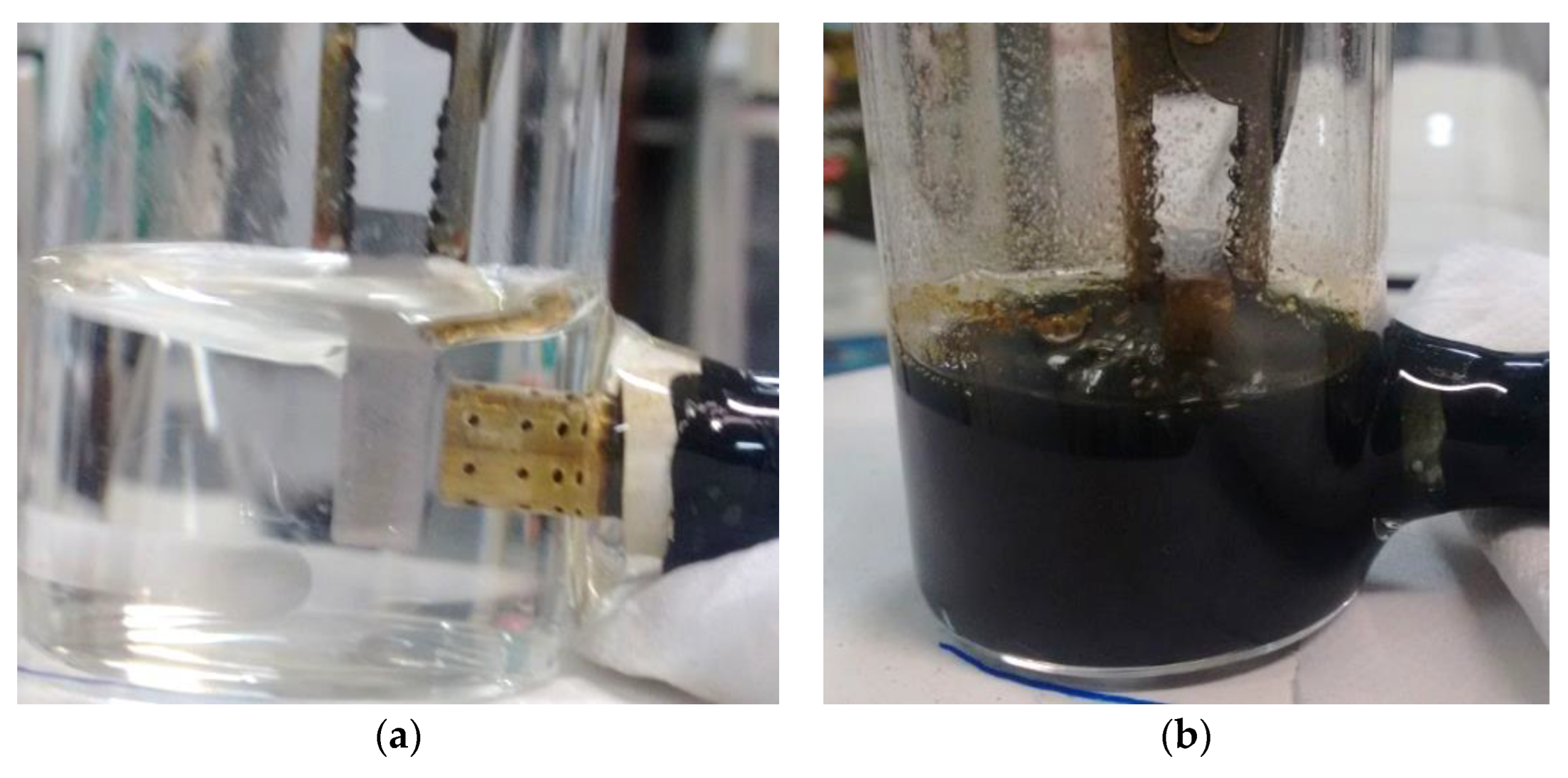
Figure 1. Scheme of a laboratory scaled-down two-electrode cell, with a metallic workpiece of SAE 4144M steel and a counter-electrode of Brass-CuZn36Pb3 alloy (a) before and (b) after the ECM process.
Processes 11 02186 g001
Figure 2. Representative SEM images of the workpieces (a) before and (b) after the ECM process in the reference electrolyte.
Processes 11 02186 g002
Figure 3. Results of electrolyte modification with EDTA. (a) Mass of sludge generated after ECM process with different EDTA concentrations, units in mg; (b) Fe–EDTA complex concentration after ECM process, obtained by UV–Vis spectroscopy (S/N = 3), units in mg L−1; (c) comparison of pH values before and after ECM process with different EDTA concentrations (S/N = 3); (d) SEM image of workpiece after ECM process using electrolyte containing EDTA [100 g L−1 NaCl combined with 15 g L−1 EDTA, pH > 10]; (e) EDTA behavior to form metal–EDTA complexes in the electrolyte (FeIII–EDTA described as an example).
Processes 11 02186 g003
Figure 4. Results of electrolyte modification with ascorbic acid (AA). (a) Mass of sludge generated after ECM process with different AA concentrations, units in mg; (b) Fen+ concentration in the electrolyte after ECM process, obtained by UV–Vis spectroscopy (S/N = 3), units in mg L−1; (c) comparison of pH values before and after ECM process in reference electrolyte and in its compositions with different AA concentrations (S/N = 3). (d) SEM image of workpiece after ECM process using electrolyte containing ascorbic acid [100 g L−1 NaCl combined with 20 g L−1 AA]; (e) overall redox reaction involving ascorbic acid and metallic ions, with iron as an example.
Processes 11 02186 g004
Table 1. Experimental parameters used in the anodic dissolution procedure.
Experimental ParameterValue
Anodic dissolution time180 s
Voltage applied5.0 V
Current density1.5 ± 0.2 A
Electrolyte temperature
(before anodic dissolution)
22 ± 3 °C
Mixing level 800~1000 RPM
Electrolyte volume30 mL
Workpiece surface area1.0 cm2
Counter-electrode surface area2.5 cm2
Table 2. ICP-OES of workpiece surfaces before and after ECM process in the proposed electrolyte compositions.
Chemical ElementSpecification (%)
SAE 4144M Steel
Workpiece before
ECM Process (%)
Workpiece after ECM Process
100 g L−1 NaCl+15 g L−1 EDTA (pH > 10.0)+20 g L−1 Ascorbic Acid (pH < 5.0)
C0.42~0.460.4530.4560.460.46
Si0.20~0.300.2680.2670.2660.269
Mn0.90~1.101.071.061.061.06
Pmax 0.0250.02510.02530.02410.0237
S0.010~0.0200.01950.0170.01780.017
Cr1.15~1.301.261.251.271.26
Nimax 0.250.1960.1980.1970.201
Mo0.25~0.350.3090.310.3090.314
Cumax 0.350.1570.1590.1590.16
FeRemaining96969696
Disclaimer/Publisher’s Note: The statements, opinions and data contained in all publications are solely those of the individual author(s) and contributor(s) and not of MDPI and/or the editor(s). MDPI and/or the editor(s) disclaim responsibility for any injury to people or property resulting from any ideas, methods, instructions or products referred to in the content.