Abstract
Dismantling the waste printed circuit boards (WPCBs) of obsolete mobile phones is essential for resource recycling and environmental protection. An automated WPCB disassembly equipment based on the hot-vibration process was designed and applied, with optimized process conditions of a heating temperature of 250 °C and an equipment amplitude of >3.66 mm. The dismantling rate for electronic components and metal shields was 98%, but disassembly of components with underfill was less effective. Both simulation and actual measurement results of the equipment’s thermal field showed that the temperature inside the disassembly bin was uniform, with a maximum temperature difference of 6–8 °C. The area of the low-temperature region accounted for approximately 5% of the total area. The acceleration ranged from 2.11 to 8.28 g when using the disassembly force model. This equipment and process can be applied to disassemble large quantities of WPCBs.
1. Introduction
According to the World Bank (2020), the number of mobile phones worldwide reached 107.521 per 100 people in 2020 [1]. In China, this number was 113.9 per 100 people, almost double from 64.4 per 100 people in 2010 [2]. Due to the rapid development of technology, mobile phones are updated faster than traditional appliances and usually used for only 1–2 years [3,4,5]. The theoretical scrap volume of mobile phones in China reached 349.22 million units in 2020, as reported by the China Household Electric Appliance Research Institute [2]. The rapid growth of mobile phone scrap volume has necessitated the resource utilization of waste mobile phones. Wasted printed circuit boards (WPCBs) are one of the core components of waste mobile phones and one of the most valuable and environmentally hazardous components for recycling [6,7]. WPCBs contain many types of valuable metals (e.g., copper, aluminum, nickel, iron, and tin), rare metals (e.g., gold, silver, and platinum), and non-metals (e.g., plastics, glass fibers, resins, and ceramics) [8]. The contents of copper, gold, silver, platinum, palladium, and other precious metals are more than ten times those of typical minerals [9]. Improper recycling of WPCBs can release various pollutants, including heavy metals (e.g., lead, mercury, and hexavalent chromium) and organic chemicals (e.g., brominated flame retardants, dibenzofurans, polycyclic aromatic compounds, chlorinated dioxin, and polybrominated diphenyl ethers) [10,11,12,13].
Researchers worldwide have developed a variety of treatment processes and equipment for WPCB recycling and resource utilization, including those based on hydrometallurgy [14,15,16,17], pyrometallurgy [18,19], supercritical fluid [20], biometallurgy [15,21], hybrid bioleaching combining hydrometallurgy [15,22], and mechanical–physical processes [23,24]. Most electronic components (ECs) in mobile phones that enter the end-of-life process prematurely can still work properly. Studies have shown that the qualification rate of properly recycled chips is about 98%, whereas that of brand-new chips is only about 95% [25]. Thus, old chips have a high recycling value, and it has many economic benefits and high environmental values for chips and other types of ECs to be treated and recycled separately after removal from the substrate when recycling precious metals from waste mobile phones [11,26].
Currently, ECs are still mainly disassembled by hand using tools such as heat guns [27]. However, manual disassembly is of low efficiency. In addition, it poses a threat to workers’ health and the surrounding environment [28,29]. In recent years, researchers worldwide have developed various pieces of equipment for disassembling ECs from WPCBs. The disassemble process is mainly divided into two steps: first, eliminating the solder joints between ECs and the substrate, and second, separating ECs from the substrate [27].
Methods for eliminating solder joint connections include using a grinder to remove the solder joints from the back of PCBs [30], using a crossflow shredder to achieve non-destructive detachment of electrical parts from PCBs [31], and using underwater explosion [32] and water jet [33]. Chemical reagents can also be used to dissolve solder joints [34]. Heating methods can also be used to melt solder joints, including hot air heating [7,35], hot liquid heating, and infrared heating; after solder joints have been removed, ECs can be separated from the substrate by such methods as mechanical scraping, gas blowing, and rotational centrifugation [36,37,38].
This study presents the design of an automated equipment for WPCB disassembly. The rationality of the design was verified through thermal field finite simulation and actual thermal measurement of the disassembly area. A vibration disassembly force model simulating thermal oil heating via electric heaters was developed to determine the operating parameters. The thermal oil warmed up the entire interior of the disassembly bin through heat conduction. During the disassembly process, the WPCBs entered the preheated area and then moved to the disassembly bin, where they exchanged heat with the internal hot air and the sieve plate, causing the solder on WPCBs to melt. At the same time, a vibration force was applied to disassemble ECs, pushing the WPCBs towards the discharge port. The equipment was tested by actual dismantling and proved to efficiently dismantle the surface mount ECs on various cell phone WPCBs. In theory, it can also be applied to dismantle components of various other WPCBs with only surface mount components soldered on them.
2. Design of the Disassembly Device
The automated disassembly equipment designed for WPCBs of mobile phones consists of a preheating rotary feeding device and a vibration dismantling device (Figure 1). The preheating rotary feeding device gradually preheats WPCBs and batches them to the vibrating desoldering device. The vibrating heating and desoldering device heats and keeps the WPCBs at high temperature to completely melt the solder, enabling the separation of components from the substrate via vibration.
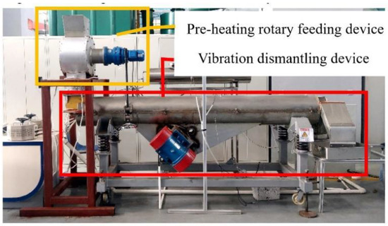
Figure 1.
Schematic diagram of the automated disassembly equipment designed for the waste printed circuit boards (WPCBs) of mobile phones.
The vibration disassembly device consists of a heating and desoldering mechanism and a vibration mechanism. Its structure is shown in Figure 2.
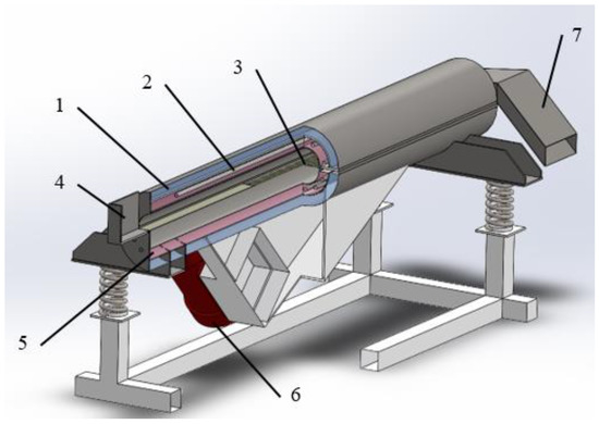
Figure 2.
Schematic diagram showing the structure of the vibration dismantling device. 1—Insulation layer; 2—electric heating tube; 3—screen plate; 4—feeding port; 5—heating layer; 6—vibration motor; 7—discharge port.
The heating and desoldering mechanism consists of a double-layer cylindrical sandwich structure with three layers: the disassembly bin, the heating layer, and the insulation layer. The disassembly bin has circular sieve plates of different diameters (22 mm, 8 mm, and 4 mm) to accommodate components of different sizes. The to-be-disassembled WPCBs are placed on the screen plate inside the heating layer. Under the sieve plate, there is a chute going from the inlet to the outlet, allowing the separated components to move quickly to the outlet. Several electric heating tubes are uniformly distributed in the heating layer, which is filled with heat-conducting oil (L-QD350#). The external inlet is covered with thermal insulation material, and an auxiliary thermal insulation electric heating sheet is installed at the bottom to reduce heat loss at the inlet. The vibration mechanism consists of two vibration motors installed symmetrically, and the vibration forces in the horizontal direction cancel each other out. Thus, the two vibration motors together provide an oblique vibration force (45°) to push the WPCBs in the disassembly bin to the outlet. The vibration force also separates the components and substrates. The discharge port is also equipped with circular sieve plates of different diameters (22 mm, 8 mm, and 4 mm) for preliminary screening of the dismantled products.
3. Research Methods
3.1. Simulation and Analysis of Thermal Field for Disassembly Equipment
The thermal field of the disassembly area was modeled using the ANSYS finite element analysis software to perform steady-state thermal analysis. The ultimate objective was to guide the design of a vibration-heated automatic disassembly equipment.
- (1)
- Geometric modeler meshing
The vibration heating automatic disassembly equipment is structured around two semi-hollow cylinders. During operation, the two semi-cylinders are bolted together to form a complete cylinder. The cylinders are mainly made of stainless steel, which has an isotropic thermal conductivity of 60.5 W/m·C. The insulation layer is filled with glass wool, with an isotropic thermal conductivity of 1 W/m·C. The heating layer is filled with heat-conducting oil, with an isotropic thermal conductivity of 20 W/m·C, and was modeled using the ANSYS finite element software. This study was focused on the thermal field in the disassembly region of the vibration dismantling device, which is a cylindrical area 3 m in length and 38 cm in diameter. After meshing, the thermal field was simulated assuming ideal boundary conditions and ignoring the influence of the rest of the device on the thermal field.
- (2)
- Heating and convection
Electric heating tubes as heating sources were arranged uniformly in the heating layer, and the temperature was set at 260 °C. Convective heat exchange occurred on the outer and inner surfaces of the shell, and room temperature was set at 25 °C.
- (3)
- Equipment thermal measurement analysis
Once the equipment was made, the thermal field of the disassembly area was measured by using uniformly arranged thermocouples to collect temperature data. The thermocouples moved 5 cm each time, and temperatures were recorded after stabilization. The recorded temperature data were used to draw the actual thermal field of the equipment’s disassembly area.
3.2. Surface Mount Device (SMD) Vibration Disassembly Force Model
The components installed on mobile phone circuit boards are SMDs, and many SMDs are soldered on both sides of circuit boards. The direction of the disassembly force can be either horizontal or vertical. These two situations are discussed separately as follows [39].
3.2.1. Vertical Disassembly Force Model for Disassembling SMDs
Once the solder on a circuit board melts, the SMDs on the lower surface of the substrate can be removed with the application of an external vertical disassembly force, which should satisfy Equation (1).
where fvi represents the vertical disassembly force applied per solder joint, gci represents the gravitational force per solder joint pin, and fsi represents the solder wetting force per solder joint and should satisfy Equation (2).
where σi represents the surface tension of the solder after melting, and θi represents the contact or dihedral angle. The wetting circumference Li is decided by the diameter d1 of solder balls, as shown in Figure 3a, and calculated as Li = π • d1. For capactiors, as shown in Figure 3b, this type of solder joint has a rectangular pin contact with length t, width b, and height h (The direction of b is perpendicular to the direction of the paper and b is not shown). The wetting perimeter Li = 2(t + b + h).
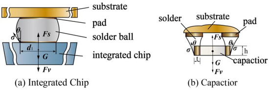
Figure 3.
Analysis of the vertical disassembly force applied to different types of surface mount devices.
For an SMD with n solder joints and a weight of G, the minimum vertical disassembly force for each solder joint can be calculated using the surface tension of the molten solder (σ), the contact angle (θ), and the wetting perimeter of each solder joint (Li).
The same method can be used for the disassembly case, where SMDs are located above the substrate, by replacing the—sign before G with a + sign in Equation (3).
3.2.2. Horizontal Disassembly Force Model for Disassembling SMDs
It is assumed that the SMDs are located above the substrate, the disassembly force is horizontally applied to the SMDs, and disassembly is hindered by the combined effect of the wetting force Fs and shear force Q (Figure 4). The joint action of the wetting force and shear force impedes disassembly. Melted solder is viscous. When the SMD is moved horizontally at a speed of v by an external force, the melted solder generates a shear force in the opposite direction of movement. If the horizontal disassembly force Fh is greater than the sum of the shear force Q and wetting force Fs, the SMD can be removed from the substrate.

Figure 4.
Analysis of the horizontal disassembly force applied to different types of surface mount devices.
Due to the extremely small thickness of the solder layer (approximately 0.1 mm), the molten solder can be modeled as a laminar viscous fluid when it is horizontally displaced by disassembly forces after melting. The shear force per unit area acting on the bottom surface of each solder joint pin is then calculated as:
where τi is the shear stress on unit area, μi is the viscosity of the molten solder, vi is the relative velocity of the solder joint pins, and di is the thickness of the solder layer.
If the bottom area of each solder joint pin is api, the shear force acting on each solder joint pin (qi) is:
For the type of pad shown in Figure 4a, if the diameter is d1, then api = πd12/4. For the type of rectangular pin shown in Figure 4b, if the length is t, width is b, and height is h, then api = b • (h + d).
The solder wetting force on the pins satisfies Equation (2), where Li is the wetting length in the direction of the pin movement. Since there is uncertainty in the direction of the component during horizontal movement, Li denotes the longest possible wetting length. For the type of solder ball that is used for chip assembly as shown in Figure 4a, Li = d1. For the type of solder joint that is used for capacitors as shown in Figure 4b, Li = max(t, b).
For an SMD with n solder joints, the molten solder surface tension is σ, the viscosity of the melting solder is μ, the contact angle is θ, the relative velocity of the pin motion is v, and the solder thickness is d. The horizontal disassembly force can be calculated as follows:
3.3. Dismantling Rate of the Equipment
After calculating the required amplitude of the machine, we verified its operation by testing different preheating times and disassembly rates at different temperatures. To obtain WPCBs of waste cell phones, we manually disassembled used cell phones purchased randomly from a recycler. We retained only the components that were soldered onto the substrate, and removed all components connected through the interface.
The vibration disassembly equipment amplitude was set to 4 mm. The preheating time was set to 5, 4.5, 4, 3.5, 3, 2.5, 2, 1.5, and 1 min. The disassembly heating temperature (the maximum preheating temperature) was set to 230 240, 250, 260, and 270 °C. A total of 45 groups of experiments were conducted, with each group consisting of three pieces of WPCBs.
The disassembly rate of this equipment is calculated using Equation (7).
where ε is the disassembly rate; n1 and n2 are the numbers of components (sieving diameter > 4 mm) before and after the WPCB disassembly, respectively.
4. Results and Discussion
4.1. Finite Element Simulation and Measured Results of Thermal Field in the Disassembly Area of the Equipment
The simulation results showed that the temperature in the disassembly area of the equipment was uniform when the equipment was well insulated and thermal compensation devices were added to both the inlet and outlet (Figure 5). The theoretical temperature difference between the disassembly areas at each heating temperature was approximately 2%, which means the temperature difference between the cold and hot areas was approximately 5–6 °C. The simulation calculation results indicate that the cylinder structure is well-designed, and the inner wall of the cylinder is close to the disassembly area, which allows heat to be rapidly transferred to the disassembly area through metal conduction, radiation, and air convection, achieving a more uniform heat distribution in the disassembly area.
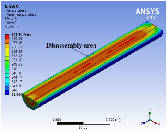
Figure 5.
Simulation results of thermal field distribution in the cross-section of the disassembly area at 260 °C.
The measured results of the thermal field in the disassembly area of this equipment are shown in Figure 6.
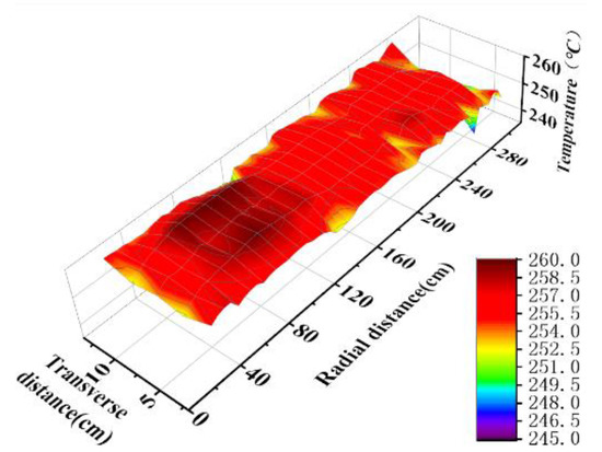
Figure 6.
Measured results of thermal field distribution in the disassembly area at 260 °C.
The measured results were consistent with the simulation results. The maximum temperature difference was 6–8 °C, and the low-temperature area with a larger temperature difference accounted for approximately 5% of the total area. However, there were several low-temperature area points in the disassembly area showing different measured results from the simulation results. This may be due to certain tolerances in the device assembly, resulting in poor fixation and reduced insulation performance. When the equipment is running, the electric heat tubes directly heat the liquid heat transfer medium. The heat transfers through the disturbed heat transfer medium rapidly and evenly, resulting in a uniform heat distribution in the metal shell. Finally, when the heat is transferred to the disassembly area through the metal shell, the heat released per unit area of the metal shell is stable, leading to a uniform distribution of the thermal field in the disassembly area and maintaining the temperature of WPCBs within a certain temperature range slightly higher than the melting point of the SMDs solder on the WPCBs. The disassembly area with smaller fluctuation in temperature can avoid the circumstance that, in order to improve the disassembly rate and increase the temperature of the cold zone, the heating power of the heating rod needs to be greatly increased, resulting in a big temperature difference between the hot and cold zones in the disassembly area. When WPCBs pass through the high-temperature region, the solder melts quickly. As no antioxidant flux is used during soldering, the hot melted solder is oxidized by oxygen. After a short period of time, an oxide film forms on the surface of the solder [40]. The melting point of oxidized solder metal is significantly higher than that of the alloy solder (for example, the melting point of tin oxide is 1630 °C, whereas that of solder Sn63Pb37 is 183 °C). Therefore, the solder surface tension σ would increase, which is unfavorable to the rapid disassembly of ECs, energy conservation, and environment protection. When the disassembly temperature is too high, the organic matter and flame retardant on the surface of WPCBs resin board would undergo volatilization or even thermal decomposition in the high-temperature area, causing serious pollution problems. When the temperature in the disassembly area is too low, the temperature of solder cannot be raised to its melting point quickly, and the rate of automatic disordering and disassembly would be significantly reduced. The lead-free solder used has a melting point of approximately 220 °C [41]. Therefore, temperature control is very important for the disassembly efficiency of the equipment. The uniform heating area of this equipment can well meet the heating requirements of the ECs on circuit boards.
4.2. Calculated Results of Vertical SMD Disassembly Force
The solder is Sn63Pb37, σ = 490 mN/m, and θ = 30°. Chips A–E and Capacitors A and B were disassembled from a Huawei P9 mobile phone. The parameters for the chips and capacitors are listed in Table 1.

Table 1.
SMD basic parameters.
The minimum vertical disassembly force (Fvmin) required to remove SMDs was calculated using Equation (3) and the results are shown in Figure 7. Fvmin was linearly related to the total wetting length , and the fitted line was (Table 2). The required Fvmin ranged from 3.14 mN (for Capacitor B) to 145.84 mN (for Chip A), and the required minimum and maximum disassembly accelerations were 1.36 and 8.18 g (g is the acceleration of gravity, 9.8 m/s2), respectively. The masses of Chip B and Capacitor B were small relative to the solder wetting force. Therefore, they required a larger disassembly acceleration (Table 3).
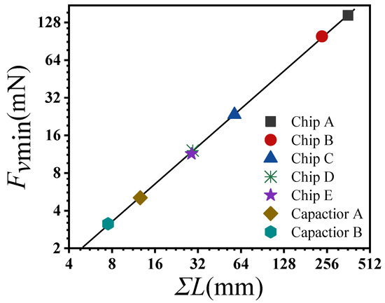
Figure 7.
Minimum vertical disassembly force (Fvmin) required for SMD disassembly.

Table 2.
Coefficients of the linear regression between vertical disassembly force and total wetting length.

Table 3.
Minimum disassembly acceleration required for SMD vertical disassembly.
The disassembly acceleration for a SMD is:
where F is the disassembly force and m is the weight of the SMD.
4.3. Calculated Results of Horizontal SMD Disassembly Force
Using the parameters in Table 4, the shear force per pin (qi) and wetting force per pin (fsi) were calculated as:

Table 4.
Analytical parameters of horizontal SMD disassembly force.
Due to the approximate millimeter size of the solder joint pins, the wetting perimeter Li (m) is approximately 1000 times larger than the solder joint pin area api (m2). Therefore, the ratio of wetting force to shear force is approximately:
For the horizontal SMD disassembly force, the shear force on each pin is much smaller than the wetting force on each pin. Therefore, the wetting force is the major hindering force during disassembly, and the shear force generated by the molten solder under the pin can be ignored. Thus, Equation (6) can be simplified as follows:
The minimum horizontal disassembly force required to dismantle an SMD is shown in Figure 8, with a range (3.18–152.78 mN) close to that of the minimum vertical disassembly force. The minimum and maximum disassembly accelerations required were 1.46 and 8.28 g, respectively.
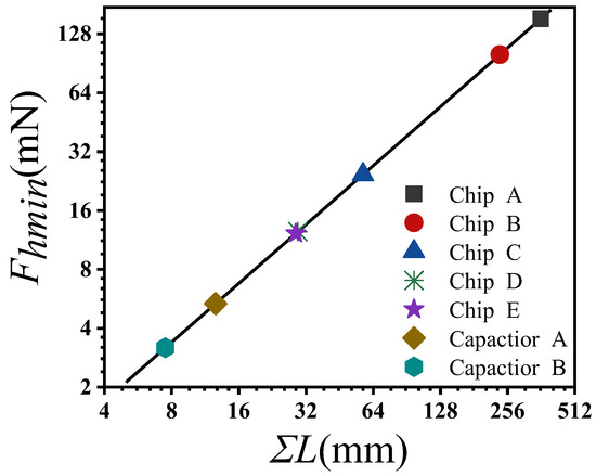
Figure 8.
Minimum horizontal disassembly force required for SMD disassembly.
4.4. Analysis of Vibration Disassembly Force Results
The SMD soldered onto the mobile phone motherboard requires a similar amount of force for horizontal and vertical disassembly. However, the components of mobile phone motherboard are very delicate, requiring a certain level of vibration acceleration during vibration disassembly. The formula for calculating the vibration sieve vibration acceleration is as follows:
where A is the amplitude and f is the vibration frequency. The vibration motor of the equipment has a fixed speed, a vibration frequency of 24 Hz, and an excitation force direction of 45° upward from the horizontal plane, ensuring that the vertical and horizontal vibration components are equal. When the vibration acceleration meets the requirement for disassembling all the SMDs (As shown in Table 3 and Table 5), the acceleration is 8.5 g and the amplitude is 3.66 mm, according to Equation (12). Therefore, both the horizontal and vertical amplitudes should be >3.66 mm.

Table 5.
Minimum disassembly acceleration required for SMD horizontal disassembly.
4.5. Result of Dismantling Rate of the Equipment
The disassembly rate results of the experiment are shown in Table 6.

Table 6.
Dismantling rate of the equipment (%).
The influencing factors of disassembly rate include preheating time and disassembly temperature. First, the influence of preheating time on disassembly rate was analyzed and is shown in Figure 9.
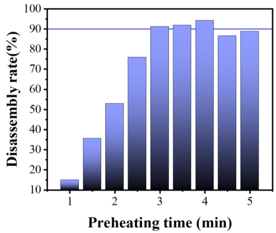
Figure 9.
Changes of disassembly rate with preheating time. The horizontal line marks the disassembly rate of 90%.
The average disassembly rate of waste circuit board chips increased rapidly when the preheating time increased from 1 to 3 min. An average disassembly rate of more than 90% was achieved when the preheating time was 3–4 min, with the highest rate of approximately 94% achieved at a preheating time of 4 min. However, the average disassembly rate decreased to below 90% when the preheating time was longer than 4 min. These results indicate that the preheating time should be controlled between 3 and 4 min.
When the preheating time was 3–4 min, high disassembly rates were achieved for all tested disassembly temperatures shown in Figure 10. However, at the disassembly temperatures of 230 °C and 270 °C, some components were not completely disassembled (Figure 11, Figure 12, Figure 13 and Figure 14).
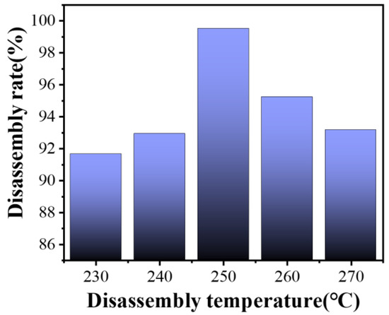
Figure 10.
Changes in disassembly rate with disassembly temperature (preheating time: 3–4 min).
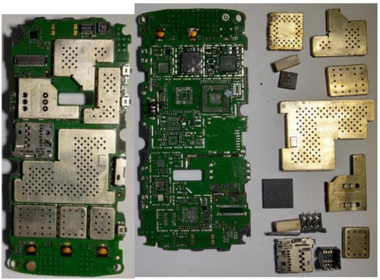
Figure 11.
The disassembly result at 230 °C with a preheating time of 4 min.
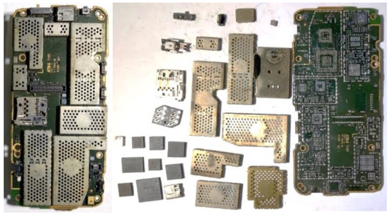
Figure 12.
The disassembly result at 270 °C with a preheating time of 4 min.
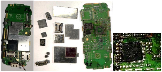
Figure 13.
The disassembly result at 270 °C with a preheating time of 3 min.
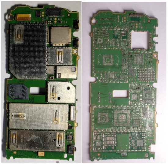
Figure 14.
The disassembly result at 250 °C with a preheating time of 4 min.
The tested temperatures were higher than the melting temperatures of commercial solders. Therefore, the components were disassembled. The device dismantling rate increased with the increasing dismantling temperature, reached its peak value of over 99% at 250 °C (not including the use of under-fill), and decreased afterwards, displaying high levels for all tested temperatures. Deviations in dismantling rate may be due to the slight differences in the circuit boards used. In summary, the dismantling temperature should be controlled at 250 °C to achieve the optimal dismantling rate.
As shown in Figure 11, Figure 12 and Figure 13, most components and all shields were disassembled at 230 °C and 270 °C, but some chips were not completely removed. At 230 °C, some of the solder did not melt completely, resulting in incomplete disassembly. At 270 °C, most components were removed, but some chips remained (Figure 15). The solder had oxidized during the repeated repair and rewelding of the phone. At 270 °C, the solder oxidized more rapidly, increasing the thickness of the oxide film. Compared with unoxidized solder, both the melting point and viscosity of the oxidized solder increased, leading to the incomplete disassembly of some components. As a result, there was residual black material around the two chip solders. Moreover, since the chip was not an LGA package chip, there was a large area of solder in the central region, which demanded a strong dismantling force. This also explains the incomplete disassembly.

Figure 15.
(a) Incompletely disassembled chips with underfill. (b) Completely disassembled chips with underfill.
At 250 °C, most of the components can be disassembled (Figure 14). However, as shown in Figure 15a, since CPU chips and ROM memory chips, the two most important chips, were fixed by underfill adhesive in addition to soldering, they were not disassembled. Usually, modified epoxy resin is used as underfill adhesive between chips and the substrates. Therefore, the underfill adhesive was stable at 250 °C. Relevant research shows that only at 400 °C and higher temperatures, does epoxy resin crack and is complete disassembly achieved. However, such a high temperature would cause considerable damage to the integrity of the components and circuit boards and generate many safety risks as well. Therefore, heating and vibration disassembly should not be applied to circuit boards with underfill components. As shown in Figure 15b, chips whose bottoms are filled with less filler can be completely disassembled, and after disassembly, only the area around the filler can be observed.
In summary, after WPCBs were preheated in the preheating rotary feeding device, the ECs of mobile phone WPCBs could be disassembled. Preheating for 4 min at 250 °C achieved disassembly rates of over 98% for chip components (sieve diameter > 4 mm) and over 90% for tiny ECs such as capacitors and resistors.
4.6. Comparison of Disassembly Costs and Carbon Emissions
Taking eight working hours per day as an example, the electricity cost is RMB 1.0 (USD0.141) per kW·h, and the labor cost is RMB 20 (USD 2.82). The rated power of the equipment is 30 kW. The feeding unit can preheat 20 PCBs every three minutes. Therefore, the processing capacity of this equipment is 20 pieces per minute. It takes 30 min for this device to reach the working temperature. Therefore, 9000 pieces of WPCBs can be disassembled per day. One worker is needed to run the equipment. Therefore, one-day running of this equipment costs a total of RMB 400 (USD 56.4), including electricity cost of RMB 240 (USD 33.8) and labor cost of RMB 160 (USD22.6). In the case of disassembling WPCBs manually using a heat gun with a rated power of 2 kW and a disassembly efficiency of 1 piece per minute, in order to achieve the same disassembly efficiency as that of the equipment, 20 workers need to work at the same time, and 9600 pieces can be disassembled per day. Therefore, the total cost would be RMB 3520 (USD 496), including electricity cost of RMB 320 (USD 45.1) and labor cost of 3200 (USD 451). It is clear that the equipment has cost advantage over manual disassembly with heat gun and also presents better energy performance when the dismantling efficiencies are the same, with 25% less carbon emissions for the same amount of WPCBs disassembled.
5. Conclusions and Prospect
Both simulation and measured results of the equipment’s thermal field showed that the maximum temperature difference was controlled between 6–8 °C, and the low-temperature area accounted for less than 5% of the total area, meeting the temperature requirements for automatic disassembly of SMDs on WPCBs.
Calculation results showed that when using vibration disassembly to remove SMDs soldered on WPCBs, the disassembly accelerations of typical SMDs ranged from 2.11 to 8.28 g.
The equipment was equipped with a fixed-speed vibration motor running at a frequency of 24 Hz. The direction of the vibration force was oblique at an upward angle of 45°. The vertical and horizontal vibration components were equal. All SMDs were disassembled. When the disassembly acceleration exceeded 8.5 g, both the horizontal and vertical direction amplitudes should be greater than 3.66 mm.
Under the optimal conditions of 3–4 min preheating time and 250 °C disassembly temperature, the disassembly rate of chip components (appearance size > 4 mm) was higher than 99%, and that of tiny ECs, such as capacitors and resistors, was higher than 90%. However, the disassembly of components with underfill was less effective. Compared to manual disassembly with a heat gun, disassembly using the equipment reduced carbon emissions by about 25% when dismantling the same quantity of WPCBs.
Currently, the equipment is a prototype, and the entire machine is heavy. The structure can be optimized in the future to reduce the weight of the machine, such as, new lightweight metal materials can be selected for manufacturing equipment.
In terms of energy conservation, one approach is to increase the thickness of the insulation layer, while another approach is to select insulation materials with better thermal insulation performance. When selecting the protective outer layer material for the insulation layer, it is possible to use low thermal conductivity metal and non-metal composite materials to minimize the energy losses caused by thermal conduction during equipment operation.
Author Contributions
Software, X.S.; Formal analysis, Q.H.; Data curation, L.Z. and Q.C.; Writing—original draft, Y.J.; Supervision, C.Z.; Project administration, M.Z.; Funding acquisition, J.W. All authors have read and agreed to the published version of the manuscript.
Funding
This research was funded by the National Key R&D Program of China (No. 2018YFC1902303), Gaoyuan Discipline of Shanghai e Environmental Science and Engineering (Resource Recycling Science and Engineering).
Data Availability Statement
Data can be accessed from corresponding author upon request.
Conflicts of Interest
The authors declare no conflict of interest.
References
- World Bank. Mobile Cellular Subscriptions (per 100 People). 2020. Available online: https://data.worldbank.org.cn/indicator/IT.CEL.SETS.P2?view=chart (accessed on 21 October 2022).
- China Institute of Home Electrical Appliances. White paper on WEEE recycling industry in China 2020. Home Appl. 2021, 6, 68–87. (In Chinese) [Google Scholar]
- Deng, W.-J.; Giesy, J.P.; So, C.S.; Zheng, H.-L. End-of-life (EoL) mobile phone management in Hong Kong households. J. Environ. Manag. 2017, 200, 22–28. [Google Scholar] [CrossRef] [PubMed]
- Gu, F.; Summers, P.A.; Hall, P. Recovering materials from waste mobile phones: Recent technological developments. J. Clean. Prod. 2019, 237, 117657. [Google Scholar] [CrossRef]
- Wilson, G.T.; Smalley, G.; Suckling, J.R.; Lilley, D.; Lee, J.; Mawle, R. The hibernating mobile phone: Dead storage as a barrier to efficient electronic waste recovery. Waste Manag. 2017, 60, 521–533. [Google Scholar] [CrossRef] [PubMed]
- Cucchiella, F.; D’Adamo, I.; Lenny Koh, S.C.; Rosa, P. A profitability assessment of European recycling processes treating printed circuit boards from waste electrical and electronic equipments. Renew. Sustain. Energy Rev. 2016, 64, 749–760. [Google Scholar] [CrossRef]
- Wang, J.; Guo, J.; Xu, Z. An environmentally friendly technology of disassembling electronic components from waste printed circuit boards. Waste Manag. 2016, 53, 218–224. [Google Scholar] [CrossRef]
- Ilyas, S.; Ruan, C.; Bhatti, H.N.; Ghauri, M.A.; Anwar, M.A. Column bioleaching of metals from electronic scrap. Hydrometallurgy 2010, 101, 135–140. [Google Scholar] [CrossRef]
- Van Eygen, E.; De Meester, S.; Tran, H.P.; Dewulf, J. Resource savings by urban mining: The case of desktop and laptop computers in Belgium. Resour. Conserv. Recycl. 2016, 107, 53–64. [Google Scholar] [CrossRef]
- Bai, J.-F.; Ji, H.-D.; Zhang, C.; Guan, J.; Wang, J. Composition of harmful volatiles in the process of separation of waste circuit board components by heating of tin furnace. J. Saf. Environ. 2013, 13, 66–70. [Google Scholar]
- Guo, J.; Zhang, R.; Xu, Z. PBDEs Emission from Waste Printed Wiring Boards during Thermal Process. Environ. Sci. Technol. 2015, 49, 2716–2723. [Google Scholar] [CrossRef]
- Huang, K.; Guo, J.; Xu, Z. Recycling of waste printed circuit boards: A review of current technologies and treatment status in China. J. Hazard. Mater. 2009, 164, 399–408. [Google Scholar] [CrossRef] [PubMed]
- Stone, R. Confronting a Toxic Blowback From the Electronics Trade. Science 2009, 325, 1055. [Google Scholar] [CrossRef]
- Jing-ying, L.; Xiu-li, X.; Wen-quan, L. Thiourea leaching gold and silver from the printed circuit boards of waste mobile phones. Waste Manag. 2012, 32, 1209–1212. [Google Scholar] [CrossRef]
- Arun, M.; Zongliang, Z.; Shine, A.-E.; Michael, L.-F.; Prashant, K.-S. E-wastes derived sustainable Cu recovery using solvent extraction and electrowinning followed by thiosulfate-based gold and silver extraction. J. Hazard. Mater. Adv. 2022, 8, 100196. [Google Scholar]
- Farhad, M.; Sina, G.; Faraz, S.; Mohammad, R. Regeneration of Sn-Pb solder from waste printed circuit boards: A hydrometallurgical approach to treating waste with waste. J. Hazard. Mater. 2020, 385, 121589. [Google Scholar]
- Mishra, G.; Jha, R.; Rao, M.D.; Meshram, A.; Singh, K.K. Recovery of silver from waste printed circuit boards (WPCBs) through hydrometallurgical route: A review. Environ. Chall. 2021, 4, 100073. [Google Scholar] [CrossRef]
- Guan, J.; Wang, J.; Min, X.; Wu, W. The Products Characteristics of Calcium-basic Compounds Pyrolysis with Waste Printed Circuit Boards (PCB). Procedia Environ. Sci. 2012, 16, 461–468. [Google Scholar] [CrossRef]
- Long, L.; Sun, S.; Zhong, S.; Dai, W.; Liu, J.; Song, W. Using vacuum pyrolysis and mechanical processing for recycling waste printed circuit boards. J. Hazard. Mater. 2010, 177, 626–632. [Google Scholar] [CrossRef]
- Golzary, A.; Abdoli, M.A. Recycling of copper from waste printed circuit boards by modified supercritical carbon dioxide combined with supercritical water pre-treatment. J. CO2 Util. 2020, 41, 101265. [Google Scholar] [CrossRef]
- Xia, M.; Bao, P.; Liu, A.; Wang, M.; Shen, L.; Yu, R.; Liu, Y.; Chen, M.; Li, J.; Wu, X.; et al. Bioleaching of low-grade waste printed circuit boards by mixed fungal culture and its community structure analysis. Resour. Conserv. Recycl. 2018, 136, 267–275. [Google Scholar] [CrossRef]
- Kanaujia, K.; Trivedi, A.; Upvan, K.; Hait, S. 6-Hybrid bioleaching—An emerging technique for extraction of critical metals from WEEE. In Environmental Management of Waste Electrical and Electronic Equipment; Hussain, C.M., Ed.; Elsevier: Amsterdam, The Netherlands, 2021; pp. 109–123. [Google Scholar]
- Liu, F.-F. Investigation of a Novel Technology of Recycling Copper Alloy Powders from Waste Printed Circuit Boards by Physical Method; South China University of Technology: Guangzhou, China, 2020. (In Chinese) [Google Scholar]
- Zhan, L.; Xu, Z. State-of-the-Art of Recycling E-Wastes by Vacuum Metallurgy Separation. Environ. Sci. Technol. 2014, 48, 14092–14102. [Google Scholar] [CrossRef]
- Sun, J.; Zhao, H. Comperhensive treatment of waste computer. Recycl. Resour. Circ. Econ. 2006, 3, 23–26. (In Chinese) [Google Scholar]
- Wu, Z.-B.; Song, G.; Meng, W.; Wang, X.; Yuan, W.; Li, J.; Liu, L.; Bai, J.; Zhang, C.; Wang, L.; et al. Assessment of precious metal value in intelligent mobile phone printed circuit boards (PCBs). Chin. J. Environ. Eng. 2018, 12, 331–337. [Google Scholar]
- Wang, J.; Xu, Z. Disposing and recycling waste printed circuit boards: Disconnecting, resource recovery, and pollution control. Env. Sci. Technol. 2015, 49, 721–733. [Google Scholar] [CrossRef] [PubMed]
- Ogunseitan, O.A. The Electronics Revolution: From E-Wonderland to E-Wasteland. Science 2009, 326, 670–671. [Google Scholar] [CrossRef] [PubMed]
- Zeng, X.; Zheng, L.; Xie, H.; Lu, B.; Xia, K.; Chao, K.; Li, W.; Yang, J.; Lin, S.; Li, J. Current Status and Future Perspective of Waste Printed Circuit Boards Recycling. Procedia Environ. Sci. 2012, 16, 590–597. [Google Scholar] [CrossRef]
- Lee, J.; Kim, Y.; Lee, J.-C. Disassembly and physical separation of electric/electronic components layered in printed circuit boards (PCB). J. Hazard. Mater. 2012, 241–242, 387–394. [Google Scholar] [CrossRef] [PubMed]
- Ueda, T.; Fukusawa, H.; Sunahara, N.; Yamada, H.; Oki, T.; Koyanaka, S. Design-of-experiment analysis of non-destructive detachment of electric parts from printed circuit boards of mobile phones using a cross-flow shredder. Waste Manag. 2021, 134, 52–56. [Google Scholar] [CrossRef] [PubMed]
- Fujita, T.; Ono, H.; Dodbiba, G.; Yamaguchi, K. Evaluation of a recycling process for printed circuit board by physical separation and heat treatment. Waste Manag. 2014, 34, 1264–1273. [Google Scholar] [CrossRef]
- Ueda, T.; Katagiri, J.; Oki, T.; Koyanaka, S. Genetic algorithm optimization in discrete element simulation of electric parts separation from printed circuit board. Struct. Multidiscip. Optim. 2021, 64, 2763–2771. [Google Scholar] [CrossRef]
- Zeng, X.; Li, J.; Xie, H.; Liu, L. A novel dismantling process of waste printed circuit boards using water-soluble ionic liquid. Chemosphere 2013, 93, 1288–1294. [Google Scholar] [CrossRef] [PubMed]
- Xiang, D.; Long, D.; Gao, L.; Duan, G.; Zhang, Y.; Xie, N.; Mou, P. Scrap Circuit Board Disassembly Equipment Using Hot Air Heating and Vibration Force. China Patent No. CN102009242A, 27 October 2010. (In Chinese). [Google Scholar]
- Zhao, Z.-w.; Wang, Y.; Song, S.; Liu, G.; Liu, Z. Develpopment and Application of Unsoldering Equipment for Printed Circuit Scraps. Modul. Mach. Tool Autom. Manuf. Tech. 2009, 10, 95–98. (In Chinese) [Google Scholar]
- Chen, M.; Wang, J.; Chen, H.; Ogunseitan, O.A.; Zhang, M.; Zang, H.; Hu, J. Electronic waste disassembly with industrial waste heat. Env. Sci. Technol. 2013, 47, 12409–12416. [Google Scholar] [CrossRef] [PubMed]
- Zhou, Y.; Qiu, K. A new technology for recycling materials from waste printed circuit boards. J. Hazard. Mater. 2010, 175, 823–828. [Google Scholar] [CrossRef] [PubMed]
- Yang, J.; Dong, X.; Wang, J.; Duan, G.; Zhang, H.C. Removal force models for component disassembly from waste printed circuit board. Resour. Conserv. Recycl. 2009, 53, 448–454. [Google Scholar] [CrossRef]
- Cai, J.-Q. Technical Development of High Performance Lead-Free Solder Pastes and Fluxes. Print. Circuit Inf. 2009, 9, 63–66. (In Chinese) [Google Scholar]
- Aamir, M.; Muhammad, R.; Tolouei-Rad, M.; Giasin, K.; Silberschmidt, V.V. A review: Microstructure and properties of tin-silver-copper lead-free solder series for the applications of electronics. Solder. Surf. Mt. Technol. 2019, 32, 115–126. [Google Scholar] [CrossRef]
Disclaimer/Publisher’s Note: The statements, opinions and data contained in all publications are solely those of the individual author(s) and contributor(s) and not of MDPI and/or the editor(s). MDPI and/or the editor(s) disclaim responsibility for any injury to people or property resulting from any ideas, methods, instructions or products referred to in the content. |
© 2023 by the authors. Licensee MDPI, Basel, Switzerland. This article is an open access article distributed under the terms and conditions of the Creative Commons Attribution (CC BY) license (https://creativecommons.org/licenses/by/4.0/).