Abstract
Indirect fracturing from roof rock to coal using a horizontal well is a new and promising technology for coalbed methane surface exploitation in soft and low-permeability coal seams. In order to study the propagation law of hydraulic fractures across the coal–rock interface, a pore pressure cohesive element is used to establish a numerical model for indirect fracturing. Combined with practical engineering in a 3# coal seam in the Xinjing mine in China, the propagation behavior of hydraulic fractures across the coal–rock interface was researched, and the range of the horizontal well position for indirect fracturing was determined. The results show that: (1) the pore pressure cohesive element can be used to accurately simulate the interaction between hydraulic fractures and natural fractures, and the propagation of hydraulic fractures across the coal–rock interface. (2) As the vertical distance between the horizontal well and coal–rock interface decreases, the breakdown pressure of perforation decreases, while the injection pressure increases when the hydraulic fracture crosses the coal–rock interface. (3) For the indirect fracturing engineering in a 3# coal seam in the Xinjing mine, the vertical distance between the horizontal well and coal–rock interface should not be larger than 2.0 m to make the hydraulic fracture propagate into the coal seams.
1. Introduction
There are approximately 36.81 trillion m3 of coalbed methane (CBM) resources in China at buried depths shallower than 2000 m [1], while most coal seams in the mining area are characterized by low saturation, low permeability, low reservoir pressure and high metamorphism [2,3]. This results in difficulties in the efficient and industrial development of CBM. In addition, the main coal-bearing basins in China have experienced long-term intense squeezing, shearing and deformation [4,5,6], which may result in problems such as hole collapse, stuck drilling and plugging when directly fracturing the coal seam. Therefore, indirect fracturing technology has been widely used in CBM extraction in recent years. The core idea of this technology is that the horizontal well is drilled in the roof or the floor, and the hydraulic fracture initiating in the roof or floor propagates into the coal seam. To date, the indirect fracturing technology has been successfully applied in the Luling mine of Huaibei [7] and in the Zhaozhuang mine of Jincheng in China [8].
The concept of indirect fracturing for CBM extraction was first proposed by Olsen et al. [9,10] at the beginning of this century, and many scholars have conducted significant work aimed at the propagation law of hydraulic fractures across the coal–rock interface. Tan et al. [11] experimentally studied fracture propagation behavior in tight sandstone-coal interbedded formations. Jiang et al. [12] experimentally studied the effect of interfacial friction and in situ stress difference on the propagation law of hydraulic fractures across the coal–rock interface. Liu et al. [13] experimentally studied the effect of injection rates of fracturing fluid on the dynamic propagation of hydraulic fractures across the coal–rock interface. Wan et al. [14] studied the influence of a transition zone on the fracture vertical propagation behavior for coal measure strata. Then, the effect of the fracture initiation position and fluid viscosity on the fracture propagation in multi-layered coal strata were experimentally investigated [15]. He et al. [16] found that, compared with hydraulic fracturing, the stress difference between the vertical stress and the minimum horizontal principal stress for cracks to penetrate through the coal–rock interface is larger in supercritical CO2 fracturing.
As for simulation work, Zhao et al. [17] established a composite criterion to predict subsequent intersection behavior between a hydraulic fracture and a natural fracture. Huang et al. [18,19], using the block discrete element method, explored the influence of engineering parameters on the behavior process of hydraulic fractures penetrating bedding planes. Escobar et al. [20] studied the effect of stress interference on the penetration ability of multiple fractures using the XFEM method, and the results showed that stress shadowing facilitates the propagation of hydraulic fractures from shale into roof rock.
To sum up, the current research around indirect fracturing for CBM extraction using a horizontal well mainly focuses on the in situ stress, rock mechanical parameters, interfacial strength and fracturing operation parameters such as the injection rate, interval distance between fracturing stages and so on. However, there is little consideration on the natural fractures, and the considered in situ stresses are restricted to the conventional normal faulting stress regime, i.e., the vertical in situ stress is the largest stress, while the strike–slip faulting stress regime in the Qinshui basin is widely distributed, i.e., the horizontal in situ stress is larger than the vertical in situ stress [21,22]. In addition, it is well known that the coal measure strata contain many natural fractures. Therefore, it is of practical importance to study the propagation law of hydraulic fractures across the coal–rock interface under the co-effect of natural fractures and tectonic stress.
In recent decades, different numerical methods have been developed to simulate the propagation of hydraulic fractures, and the most widely used methods include the displacement discontinuity method (DDM) [23], extend finite element method (XFEM) [24], boundary element method (BEM) [25] and discrete element method (DEM) [26]. The underlying assumptions of the DDM are based on linear elastic fracture mechanics (LEFM), so it is only applicable to brittle rocks, which limits its applications in quasi-brittle/ductile rocks such as coal. The DDM assumes homogenous properties, so it is not fit for multi-layer formations. Furthermore, to simulate the interaction between a hydraulic fracture and natural fracture, most DDM models require a pre-defined crossing criterion that is derived from the assumptions of the plain strain condition, infinite elastic domain and local Mohr–Coulomb law, so it is challenging to apply the DDM in naturally fractured formations. The XFEM is still challenging to simulate the interaction between a hydraulic fracture and natural fracture, even for 2D case. In addition, the parallel computation of XFEM is inefficient. The BEM results in efficient and accurate fracture propagation in elastic homogeneous media. However, its main advantage, discretizing only the boundary of the body, can become a serious challenge in problems with unknown boundaries, such as crack propagation, which need re-meshing and can lead to simulation difficulties. In addition, the BEM is not fit for heterogeneous formations. As to the DEM, it requires much finer meshes not applicable in the geological formation scales.
The cohesive zone finite element method, which has its origin in the concepts of a cohesive zone model for fractures originally proposed by Barenblatt [27] and Dugdale [28], has been widely used with great success to simulate the fracture and fragmentation process in quasi-brittle and composite materials. The cohesive zone model assumes the existence of a simplified fracture process zone (FPZ) characterized by a traction–separation law. Thus, the cohesive zone model avoids the singularity in the crack tip stress field that is present in the LEFM. In addition, the cohesive zone model fits naturally into the conventional finite element method, and thus can be easily implemented. As a special finite element characterizing the cohesive zone model, the pore pressure cohesive element can accurately reflect fluid–solid coupling and simulate the interaction between a hydraulic fracture and discontinuities. Therefore, the pore pressure cohesive element is used to simulate the hydraulic fracture propagation across the coal–rock interface and the interaction with natural fractures in the present work.
In this paper, the applicability of the pore pressure cohesive element to the simulation of the interaction between a hydraulic fracture and natural fracture and the propagation of hydraulic fractures across the coal–rock interface is validated. Then, considering the natural fracture distribution and tectonic stress field of 3# coal seams of the Xinjing mine in the Shanxi province in China, we established a numerical model for indirect fracturing from the roof to coal, using the propagation laws of hydraulic fracture across the coal–rock interface that was studied, and the required location of the horizontal well in the roof for the hydraulic fracture propagating into the coal from the roof was determined. Note that in the built numerical model, the natural fractures are represented by the pore pressure cohesive elements with zero thickness embedded in the pre-defined path. This research can provide a theoretical basis for the CBM extraction in natural fractured coal seams with a tectonic stress field using indirect fracturing.
2. Cohesive Element Model for Hydraulic Fracturing
As a special finite element, the cohesive element has been widely used to simulate fracture propagation. In terms of hydraulic fracturing simulation, the pore pressure cohesive element with zero thickness is used to pre-define the propagation path of a hydraulic fracture. As shown in Figure 1, the fracture process zone (FPZ, i.e., the unbroken cohesive zone) at the tip of the hydraulic fracture is simulated using a partially damaged cohesive element with non-zero traction T, while the visible fracture (i.e., the broken cohesive zone) is simulated using the completely damaged cohesive element with the traction T of zero. The mathematic crack tip refers to the point which is yet to separate. The cohesive crack corresponds to the damage initiation point where the traction T reaches the tensile strength Tmax and the separation δ between the top and bottom surface of the cohesive element reaches the critical value δ0, and the material crack tip is the completely damaged point where δ reaches the critical value δf and the cohesive strength just vanishes [29,30,31].
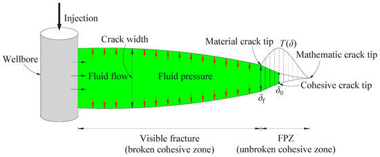
Figure 1.
Cohesive element model for hydraulic fracturing.
2.1. Equations Governing the Solid Deformation
The linear elastic constitutive relation is adopted to describe the coal and rock deformation. Specifically, T represents the nominal traction vector subjected to the top and bottom surfaces of the cohesive element. For a 2D numerical model, T consists of two components, i.e., the one perpendicular to the surface of the cohesive element and the one parallel to the surface of cohesive element, which are denoted by Tn and Ts, respectively. The corresponding separations between the top and bottom surfaces of the cohesive element are denoted by δn and δs, respectively. The initial constitutive thickness of the cohesive element is denoted by h0, and then the nominal normal strain and shear strain can be defined as
Correspondingly, the linear elastic constitutive relation can be written as
As the default value of h0, 1.0 is used in the following simulation, so E in Equation (2) is the stiffness matrix, and Tn and Ts are the normal stress and shear stress, respectively.
2.2. Equations Governing the Damage and Fracture
The irreversible bilinear traction–separation law [32] is adopted to simulate the damage process of the cohesive element, as shown in Figure 2. K0 is the initial stiffness of a cohesive element without damage (δ < δ0). When δ = δ0, the cohesive element damage occurs, and the traction T reaches the peak value equal to the material tensile/shear strength. When δ > δ0, the cohesive element experiences damage evolution, and D is the damage factor. When δ increases to δf, the cohesive element fails completely, forming a visible fracture. Therefore, δf is the fracture displacement and the area under the solid red line is equal to the fracture energy Gc.
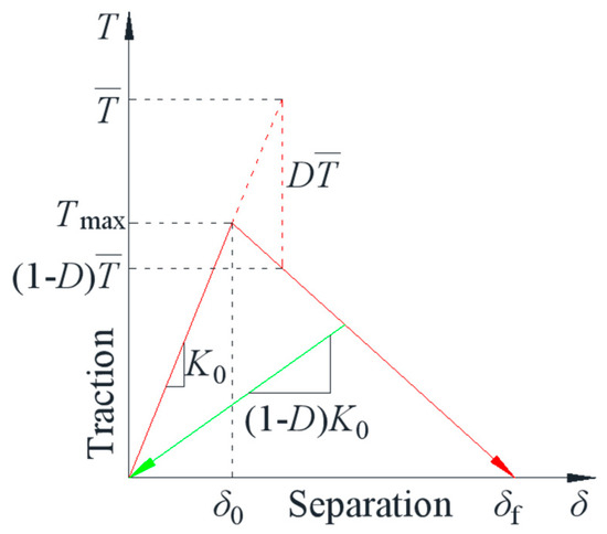
Figure 2.
Irreversible bilinear traction–separation law.
The maximum nominal stress criterion is adopted to define the damage initiation in this work. This criterion assumes that the damage is to initiate when the maximum nominal stress ratio (as defined in the expression below) reaches 1.0 and can be written as
where and represent the peak values of the nominal stress when the deformation is either purely normal to the interface or purely in the shear direction, respectively.
Two types of simplified criteria based on the fracture displacement δf and fracture energy Gc are used to determine the tensile failure of a cohesive element, and the linear friction law written as in Equation (4) is used to determine the shear failure of the cohesive element.
where f is the coefficient of friction, σn is the normal compressive stress, τs is the frictional shear stress and τmax is the shear stress limit on the contacting surfaces.
2.3. Equations Governing the Fluid Flow
The fluid constitutive response within the gap between the cohesive surfaces comprises the tangential flow and the normal flow (i.e., leakage flow), as shown in Figure 3. The fracturing fluid is assumed to be incompressible Newtonian fluid, and its flow can be characterized using the Reynolds lubrication equation as [33,34]
where w(x, t) is the crack width, t is the injection time, x is the distance to the wellbore and ct and cb are fluid leak-off coefficients for the top and bottom surfaces of the cohesive element, respectively. pi is the fluid pressure, and pt and pb are the pore pressures in the adjacent pore fluid material on the top and bottom surfaces of the cohesive element, respectively. μ is the fluid viscosity, Q(t) is the injection rate and δ(x) is the Dirac delta function.
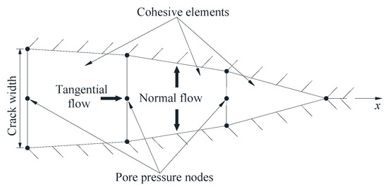
Figure 3.
Fluid flow within cohesive elements.
2.4. Model Implementation
The finite element code ABAQUS/Standard [35] is used for the numerical simulation analysis. The initially unopened fracture is represented by an embedded array of pore pressure cohesive elements without initial separation along the entire fracture path. As to the generation of the random natural fractures, the Python code is combined with the above finite element code to represent the path of natural fractures, and then the pore pressure cohesive elements are embedded along this path to generate the natural fractures. In addition, the rock matrix was simulated using the solid element with the linear elastic constitutive described in Section 2.1.
3. Model Verification
3.1. Comparison with Blanton’s Criteria
Aimed at the interaction between the hydraulic fracture and the pre-existing fracture shown in Figure 4, Blanton [36] proposed the criteria for the opening of pre-existing fractures and the arrest of hydraulic fractures, respectively.
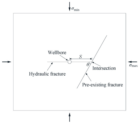
Figure 4.
Diagram of a hydraulic fracture intersecting a pre-existing fracture.
The opening criterion can be written as
and the arrest criterion can be written as
where S is the horizontal distance between the wellbore and the pre-existing fracture, and θ is the intersection angle.
The numerical model setup is shown in Figure 5 and the major input parameters are listed in Table 1. In the series of simulations, the horizontal distance between the injection node and the pre-existing fracture is fixed as 7.5 m, the length of the pre-existing fracture is fixed as 6 m and the initial length of the hydraulic fracture is fixed as 7 m.
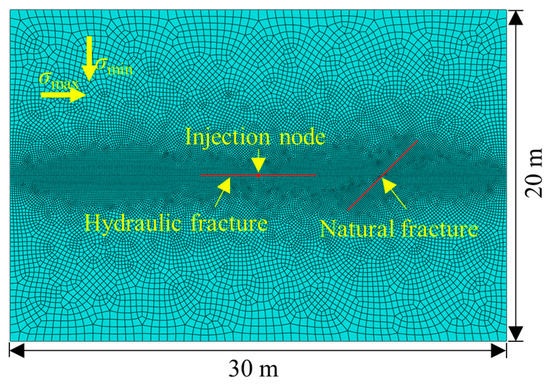
Figure 5.
Model setup for the interaction between a hydraulic fracture and natural fracture.

Table 1.
Model parameters for the interaction between a hydraulic fracture and natural fracture.
The three typical interaction models, i.e., the natural fracture opening, the hydraulic fracture arrest and the hydraulic fracture crossing, can be simulated successfully using the pore pressure cohesive element, as shown in Figure 6. The comparison between the numerical results and Blanton’s criteria is shown in Figure 7, from which it can be found that the scatter points representing the opening, arrest and crossing from the numerical simulation all fall in the corresponding analytic area, indicating the consistency between the analytic solution and the numerical results. Therefore, the pore pressure cohesive element can accurately simulate the interaction between the hydraulic fracture and the natural fracture.
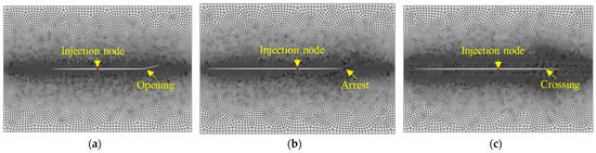
Figure 6.
Interaction between the hydraulic fracture and natural fracture from the present model; (a) σmax − σmin = 0 MPa, θ = 15°; (b) σmax − σmin = 2 MPa, θ = 45°; (c) σmax − σmin = 4 MPa, θ = 75°.
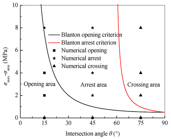
Figure 7.
Comparison between numerical results and Blanton’s criteria.
3.2. Comparison with Indirect Fracturing Experiment
Using the coal–cement blocks with interfaces lubricated by oil grease or Vaseline, Jiang et al. [12] studied the effect of the stress difference and the interfacial friction on hydraulic fracture propagation across the coal–rock interface. The physical and mechanics parameters of coal and cement blocks are listed in Table 2. According to Jiang’s experiment, the numerical model is set as Figure 8 and the input parameters are listed in Table 3. Note that, in our simulation, the shear strength of the coal–cement interface was input based on the linear friction law, and the elastic modulus of the interface was input equating to half of the sum of that of the coal and the cement.
Table 2.
Physical and mechanics parameters of Jiang’s laboratory experiment [12].
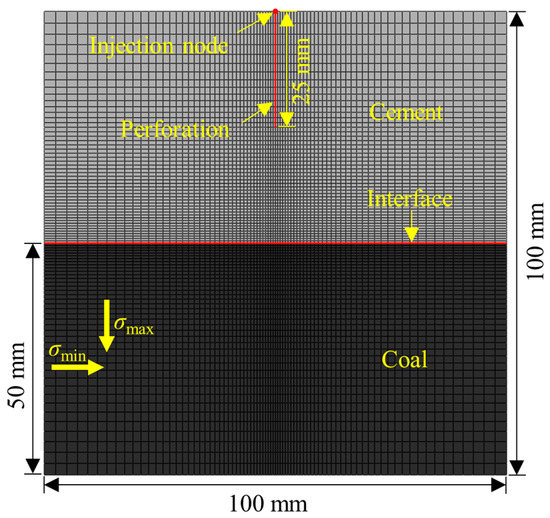
Figure 8.
Model setup for indirect fracturing from cement to coal.
Table 3.
Model parameters for indirect fracturing from cement to coal.
The comparison between the numerical results and the experimental results is listed in Table 4. It can be found that the numerical results agree well with the experimental results, indicating the applicability of the pore pressure cohesive element to the simulation of the hydraulic fracture propagation across the coal–rock interface.
Table 4.
Comparison between numerical simulation and Jiang’s experiment.
4. Engineering Application
4.1. Numerical Model for CBM Extraction Using Indirect Fracturing
The site measurement results shows that the Xinjing mine of the Shanxi province in China belongs to a strike–slip faulting stress regime, i.e., σH > σv > σh. The mean in situ stress is σv = 8.74 MPa, σH = 11.34 MPa and σh = 3.55 MPa. The samples including coal, roof and floor are obtained from the 3# coal seam, the coal was cut using a wire cutting machine to analyze the natural fracture distribution, as shown in Figure 9, and the statistical result of the natural fractures in the coal is listed in Table 5.
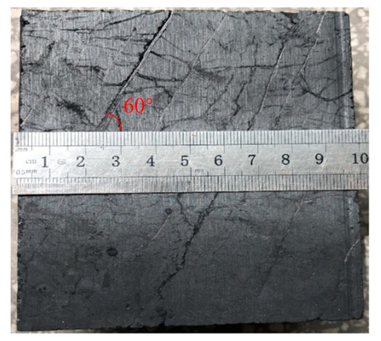
Figure 9.
Natural fractures distribution in coal.
Table 5.
Statistical result of the natural fractures in coal.
Combined with the geological condition of the 3# coal, the numerical model for indirect fracturing from the roof to the coal is established, as shown in Figure 10. Note that the natural fractures are embedded into the numerical model using the Python language based on the statistical result shown in Table 5. The perforation depth is set as 0.6m, and the propagation law of hydraulic fractures across the coal–rock interface is studied by changing the distance between the horizontal well and the coal, i.e., H. To minimize the dependence of the fracture propagation path on the embedded location of the pore pressure cohesive element and reflect truly the fracture propagation process, the pore pressure cohesive elements were globally embedded between all the solid elements.
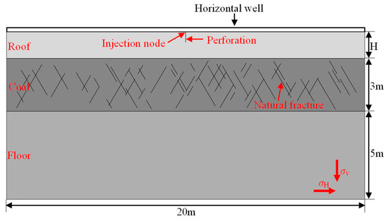
Figure 10.
Model setup for CBM extraction using indirect fracturing.
The mechanical parameters of the coal, roof and floor were obtained using the uniaxial compression test, Brazilian split test and semi-circular specimens under the three-point bending test. In addition, the height of the hydraulic fracture was estimated as 5 m and the injection rate in the simulation was set as 0.001 m3/s. Considering the actual fracturing parameters with a perforation interval of 3 m and perforation density of 10 in 1 m, the injection rate of 0.001 m3/s in the simulation corresponds to that of 9 m3/s in actual engineering. The specific input parameters for the numerical model are listed in Table 6.
Table 6.
Model parameters for CBM extraction using indirect fracturing.
4.2. Results Analysis
The propagation paths of a hydraulic fracture for the different values of H are shown in Figure 11, from which it can be found that, when H = 0.7 m, 1.0 m and 1.5 m, the hydraulic fracture can propagate into the coal from the roof; when H ≥ 2.0 m, the hydraulic fracture cannot propagate into the coal. Therefore, in terms of the indirect fracturing for CBM extraction in the 3# coal of the Xinjing mine, the distance between the horizontal well in the roof and the coal should be smaller than 2.0 m.
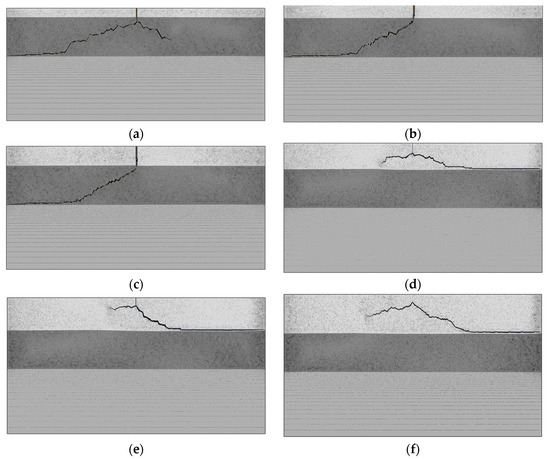
Figure 11.
Propagation path of a hydraulic fracture under different horizontal well drilling positions. (a) H = 0.7 m; (b) H = 1.0 m; (c) H = 1.5 m; (d) H = 2.0 m; (e) H = 2.5 m; (f) H = 3.0 m.
The injection pressure–injection time curve under different horizontal well drilling positions was extracted, as shown in Figure 12, from which the perforation breakdown pressure and the crossing pressure (i.e., the injection pressure at the time when the hydraulic fracture just propagates to the interface) were recorded in Table 7, respectively.
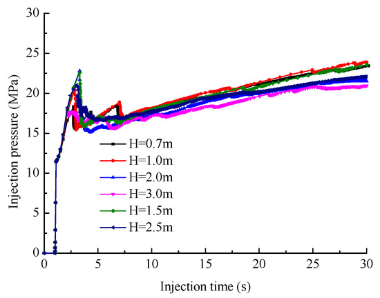
Figure 12.
Injection pressure under different horizontal well drilling positions.
Table 7.
Fracturing characteristic parameters under different horizontal well drilling positions.
It can be found from Figure 11 and Table 7 that the perforation breakdown pressure increases with increasing H and this phenomenon is more obvious when H is small (H = 0.7 m, 1.0 m and 1.5 m). The mechanical mechanism for this phenomenon is that the incompatible deformation between the roof and coal induces the tensile internal stress when fracturing, and the induced tensile stress increases with decreasing H. Therefore, as the horizontal well drilling position H increases, the breakdown pressure increases but increment decreases.
It can be found from Table 7 that, for H = 0.7 m, 1.0 m and 1.5 m, the hydraulic fracture can propagate into the coal but the crossing pressure decreases with increasing H. The reason for this is that when H is large, the released elastic strain energy due to the roof fracture is more, the part of the elastic strain energy is transformed into the surface energy of the hydraulic fracture and the other is consumed to overcome the fracture propagation resistance, keeping the continuous propagation of the hydraulic fracture in the coal.
In addition, it can be found from Figure 11a–c that only one or two dominant hydraulic fracture propagation paths exist and the complex fracturing networks cannot be obtained, in spite of the fact that many natural fractures are pre-defined in the numerical model. If the stimulated natural fractures are not well connected to the main hydraulic fracture, they have little contrition to production enhancement [37]. In any case, once the advantage of the dominant fractures is established, the trend of “Matthew Effect” is inevitable, resulting in the simple fracture networks. Therefore, even though the natural fractures are numerous in naturally fractured formations, the complex fracturing networks cannot be guaranteed, and the fracturing networks also depend on the tensile strength and shear strength of the natural fracture, and the distance between the natural fractures and the dominant hydraulic fracture, unless the natural fractures already formed “networks” in the first place [38].
5. Discussion
The present work analyzed the co-effect of natural fractures and tectonic stress on hydraulic fracture propagation across the coal–rock interface, which is of significance for the CBM exploitation using indirect fracturing. The adopted numerical model in the present work is a 2D model, which cannot truly reflect the propagation process of the hydraulic fracture, especially for the layered formations with tectonic stress. In the layered formations with tectonic stress, the 2D model can simulate the results that the hydraulic fracture crosses the interface, while the 3D model may simulate the arrest or interface opening due to the development of the hydraulic fracture in the direction of height. Therefore, the effect of tectonic stress on the crossing behavior of a hydraulic fracture in a layered formation should be studied further using a 3D model.
In addition, the study of the effect of natural fractures on hydraulic fracture propagation across the coal–rock interface is limited in the final fracturing networks in the present work, ignoring the effect of natural fractures on the hydraulic fracture propagation characteristics such as the breakdown pressure, the injection pressure at the time when the hydraulic fracture just propagates to the interface and the propagation speed in the roof. These characteristics have a significant impact on the final fracturing networks and need to be studied further in following research.
6. Conclusions
- Pore pressure cohesive elements can be used to accurately simulate the propagation of the hydraulic fracture across the coal–rock interface in coal measure strata and the interaction between hydraulic fracture and natural fracture.
- As the horizontal well drilling position decreases, the perforation breakdown pressure decreases while the crossing pressure increases. The mechanical mechanism for this phenomenon is that the incompatible deformation between the roof and coal induces the tensile internal stress when fracturing, and the induced tensile stress increases with decreasing H.
- Considering the co-effect of natural fractures and tectonic stress in the 3# coal of the Xinjing mine of the Shanxi province in China, it is suggested that the horizontal well drilling position should be smaller than 2.0 m when indirectly fracturing the coal from the roof to ensure that the hydraulic fracture can propagate into the coal successfully.
Author Contributions
Conceptualization, D.Z.; methodology, D.Z.; software, D.Z.; validation, W.L.; investigation, D.N.; resources, H.X.; writing—original draft preparation, D.Z.; supervision, W.L.; project administration, X.S.; funding acquisition, X.S. All authors have read and agreed to the published version of the manuscript.
Funding
This research was funded by the Basic Research Program of Shanxi Province, China (No. 202103021224059), Taiyuan University of Technology-Huayang new material technology group Co., Ltd. Cooperation Project (No. 2020007899), Science and Technology Major Project Shanxi Province (No. 20201102002) and Basic Research Program of Shanxi Province, China (No. 20210302124664).
Data Availability Statement
Data are contained in the article.
Conflicts of Interest
The authors declare no conflict of interest.
References
- Qin, Y.; Moore, T.; Shen, J.; Yang, Z.; Shen, Y.; Wang, G. Resources and geology of coalbed methane in China: A review. Int. Geol. Rev 2018, 60, 777–812. [Google Scholar] [CrossRef]
- Yuan, L.; Xue, J.; Zhang, N.; Lu, P. Development orientation and status of key technology for mine underground coal bed methane drainage as well as coal and gas simultaneous mining. Coal Sci. Technol. 2013, 41, 6–11. (In Chinese) [Google Scholar]
- Lau, H.; Li, H.; Huang, S. Challenges and opportunities of coalbed methane development in China. Energy Fuels 2017, 31, 4588–4602. [Google Scholar] [CrossRef]
- Li, L.; Liu, D.; Cai, Y.; Wang, Y.; Jia, Q. Coal structure and its implications for coalbed methane exploitation: A review. Energy Fuels 2021, 35, 86–110. [Google Scholar] [CrossRef]
- Cheng, Y.; Pan, Z. Reservoir properties of Chinese tectonic coal: A review. Fuel 2020, 260, 116350. [Google Scholar] [CrossRef]
- Cheng, Y.; Lei, Y. Causality between tectonic coal and coal and gas outbursts. J. China Coal Soc. 2021, 46, 180–198. (In Chinese) [Google Scholar]
- Zhang, Q.; Ge, C.; Li, W.; Jiang, Z.; Chen, J.; Li, B.; Wu, J.; Wu, X.; Liu, J. A new model and application of coalbed methane high efficiency production from broken soft and low permeable coal seam by roof strata-in horizontal well and staged hydraulic fracture. J. China Coal Soc. 2018, 43, 150–159. (In Chinese) [Google Scholar]
- Xu, Y.; Guo, S. Technology and application of staged fracturing in coalbed methane horizontal well of soft and hard coal composite coal seam. J. China Coal Soc. 2019, 44, 1169–1177. (In Chinese) [Google Scholar]
- Olsen, T.N.; Bratton, T.R.; Donald, A.; Koepsell, R.; Tanner, K. Application of indirect fracture for efficient stimulation of coalbed methane. In Proceedings of the SPE Rocky Mountain Oil & Gas Technology Symposium, Denver, CO, USA, 16–18 April 2007. [Google Scholar]
- Olsen, T.N.; Brenize, G.; Frenzel, T. Improvment process of coalbed natural gas completion and stimulation. In Proceedings of the SPE Annual Technical Conference and Exhibition, Denver, CO, USA, 5–8 October 2003. [Google Scholar]
- Tan, P.; Jin, Y.; Yuan, L.; Xiong, Z.; Hou, B.; Chen, M.; Wan, L. Understanding hydraulic fracture propagation behavior in tight sandstone–coal interbedded formations: An experimental investigation. Pet. Sci. 2019, 16, 148–160. [Google Scholar] [CrossRef]
- Jiang, Y.; Lian, H.; Nguyen, V.P.; Liang, W. Propagation behavior of hydraulic fracture across the coal-rock interface under different interfacial friction coefficients and a new prediction model. J. Nat. Gas Sci. Eng. 2019, 68, 102894. [Google Scholar] [CrossRef]
- Liu, J.; Yao, Y.; Liu, D.; Xu, L.; Elsworth, D.; Huang, S.; Luo, W. Experimental simulation of the hydraulic fracture propagation in an anthracite coal reservoir in the southern Qinshui Basin, China. J. Pet. Sci. Eng. 2018, 168, 400–408. [Google Scholar] [CrossRef]
- Wan, L.; Hou, B.; Tan, P.; Chang, Z.; Muhadasi, Y. Observing the effects of transition zone properties on fracture vertical propagation behavior for coal measure strata. J. Struct. Geol. 2019, 126, 69–82. [Google Scholar] [CrossRef]
- Wan, L.; Hou, B.; Meng, H.; Chang, Z.; Chen, M. Experimental investigation of fracture initiation position and fluid viscosity effect in multi-layered coal strata. J. Pet. Sci. Eng. 2019, 182, 106310. [Google Scholar] [CrossRef]
- He, W.; Lian, H.; Liang, W.; Wu, P.; Jiang, Y.; Song, X. Experimental Study of Supercritical CO2 Fracturing Across Coal–Rock Interfaces. Rock Mech. Rock Eng. 2023, 56, 57–68. [Google Scholar] [CrossRef]
- Zhao, Y.; Zhang, Y.; He, P. A composite criterion to predict subsequent intersection behavior between a hydraulic fracture and a natural fracture. Eng. Fract. Mech. 2019, 209, 61–78. [Google Scholar] [CrossRef]
- Huang, L.; Dontsov, E.; Fu, H.; Lei, Y.; Weng, D.; Zhang, F. Hydraulic fracture height growth in layered rocks: Perspective from DEM simulation of different propagation regimes. Int. J. Solids Struct. 2022, 238, 111395. [Google Scholar] [CrossRef]
- Zheng, Y.; He, R.; Huang, L.; Bai, Y.; Wang, C.; Chen, W.; Wang, W. Exploring the effect of engineering parameters on the penetration of hydraulic fractures through bedding planes in different propagation regimes. Comput. Geotech. 2022, 146, 104736. [Google Scholar] [CrossRef]
- Escobar, R.G.; Mejia, S.E.C.; Roehl, D.; Romanel, C. XFEM modeling of stress shadowing in multiple hydraulic fractures in multi-layered formations. J. Nat. Gas Sci. Eng. 2019, 70, 102950. [Google Scholar] [CrossRef]
- Zhang, P.; Meng, Z.; Jiang, S.; Chen, X. Characteristics of in-situ stress distribution in Zhengzhuang Region, Southern Qinshui Basin, China and its stress path during depletion. Eng. Geol. 2020, 264, 105413. [Google Scholar] [CrossRef]
- Hou, X.; Liu, S.; Li, G.; Zhu, Y.; Liu, A. Quantifying and modeling of in situ stress evolutions of coal reservoirs for Helium, Methane, Nitrogen and CO2 depletions. Rock Mech. Rock Eng. 2021, 54, 3701–3719. [Google Scholar] [CrossRef]
- Shrivastava, K.; Sharma, M.M. Mechanisms for the formation of complex fracture networks in naturally fractured rocks. In Proceedings of the SPE Hydraulic Fracturing Technology Conference and Exhibition, Woodlands, TX, USA, 23–25 January 2018. [Google Scholar]
- Willbrand, K.; Siebert, P.; Weber, N.; Fries, T.P.; Feinendegen, M.; Ziegler, M.; Clauser, C. Development of a numerical tool for EGS-layout calculations based on 3D XFEM fracture propagation. In Proceedings of the World Geothermal Congress, Melbourne, VIC, Australia, 19–25 April 2015. [Google Scholar]
- Wong, S.; Geilikman, M.; Xu, G. The geomechanical interaction of multiple hydraulic fractures in horizontal wells. In Effective and Sustainable Hydraulic Fracturing; Jeffrey, R., Ed.; InTechOpen: London, UK, 2013. [Google Scholar]
- Huang, K.; Zhang, Z.; Ghassemi, A. Modeling three-dimensional hydraulic fracture propagation using virtual multidimensional internal bonds. Int. J. Numer. Anal. Methods Geomech. 2012, 37, 2021–2038. [Google Scholar] [CrossRef]
- Barenblatt, G.I. The mathematical theory of equilibrium of cracks in brittle fracture. Adv. Appl. Mech. 1962, 7, 55–129. [Google Scholar]
- Dugdale, D.S. Yielding of steel sheets containing slits. J. Mech. Phys. Solids 1960, 8, 100–104. [Google Scholar] [CrossRef]
- Chen, Z.; Bunger, A.P.; Zhang, X.; Jeffrey, R.G. Cohesive zone finite element-based modeling of hydraulic fractures. Acta Mech. Solida Sin. 2009, 22, 443–452. [Google Scholar] [CrossRef]
- Guo, J.; Luo, B.; Lu, C.; Lai, J.; Ren, J. Numerical investigation of hydraulic fracture propagation in a layered reservoir using the cohesive zone method. Eng. Fract. Mech. 2017, 186, 195–207. [Google Scholar] [CrossRef]
- Tan, P.; Jin, Y.; Pang, H. Hydraulic fracture vertical propagation behavior in transversely isotropic layered shale formation with transition zone using XFEM-based CZM method. Eng. Fract. Mech. 2021, 248, 107707. [Google Scholar] [CrossRef]
- Tomar, V.; Zhai, J.; Zhou, M. Bounds for element size in a variable stiffness cohesive finite element model. Int. J. Numer. Methods Eng. 2004, 61, 1894–1920. [Google Scholar] [CrossRef]
- Peirce, A.; Detournay, E. An implicit level set method for modeling hydraulically driven fractures. Comput. Methods Appl. Mech. Eng. 2008, 197, 2858–2885. [Google Scholar] [CrossRef]
- Chen, Z. Finite element modelling of viscosity-dominated hydraulic fractures. J. Pet. Sci. Eng. 2012, 88–89, 136–144. [Google Scholar] [CrossRef]
- Dassault Systemes Simulia Corporation. Abaqus 2016 Documentation; Dassault Systemes Simulia Corporation: Providence, RI, USA, 2016. [Google Scholar]
- Blanton, T.L. An experimental study of interaction between hydraulically induced and pre-existing fractures. In Proceedings of the SPE/DOE Unconventional Gas Recovery Symposium of the Society of Petroleum Engineers, Pittsburgh, PA, USA, 16–18 May 1982. [Google Scholar]
- Wang, H. What factors control shale gas production and production decline trend in fractured systems: A comprehensive analysis and investigation. SPE J. 2017, 22, 562–581. [Google Scholar] [CrossRef]
- Wang, H. Hydraulic fracture propagation in naturally fractured reservoirs: Complex fracture or fracture networks. J. Nat. Gas Sci. Eng. 2019, 68, 102911. [Google Scholar] [CrossRef]
Disclaimer/Publisher’s Note: The statements, opinions and data contained in all publications are solely those of the individual author(s) and contributor(s) and not of MDPI and/or the editor(s). MDPI and/or the editor(s) disclaim responsibility for any injury to people or property resulting from any ideas, methods, instructions or products referred to in the content. |
© 2023 by the authors. Licensee MDPI, Basel, Switzerland. This article is an open access article distributed under the terms and conditions of the Creative Commons Attribution (CC BY) license (https://creativecommons.org/licenses/by/4.0/).