Abstract
Rural power grids are essential for rural development, impacting the lives of farmers, the agricultural economy, and the overall efficiency of agricultural production. To ensure the reliable operation of these grids, finding ways to provide high-quality power is imperative. In recent years, the penetration rate of distributed photovoltaic (PV) in the distribution network has been increasing. When the output of PV and load are not matched, the voltage fluctuation of the network affects the safe and stable operation of the distribution network. In this study, we propose that the stable operation of rural power grids can be achieved by employing a photovoltaic-electric spring (PV-ES) device. A state space model of PV-ES is established and a single PV-ES voltage control method, based on a PI controller, is proposed, taking a rural user household with a monthly power consumption of about 120 access to distributed power supply as an example. We analyzed the device’s effectiveness in addressing voltage fluctuation issues as well as how light intensity impacts its effectiveness. The implementation of the PV-ES device solves the most significant problem faced by rural power grids, namely, the unstable power supply that occurs during peak electricity consumption periods. In addition, the PV-ES device ensures a high-quality electricity consumption experience for consumers.
1. Introduction
Constrained by urban–rural divisions that prioritize cities, rural power grids are often outdated and poorly maintained [1], leaving the rural power supply, and the services that rely on it, at a disadvantage. With rural revitalization projects on the rise, the demand for electric energy in rural areas is increasing, and the scale of power grid construction projects is expanding. Rural power grid construction, a vital component of rural infrastructure, plays a crucial role in enhancing agricultural production efficiency, improving the rural environment, and raising farmers’ living standards. “Carbon peak and carbon neutrality” is a long-term energy goal for China’s future, and the development of distributed renewable energy system [2] can contribute to the realization of this goal. In recent years, the Chinese government has launched a series of policies to promote the development of distributed PV, building rooftop-distributed PV [3] across the county to promote the work’s official launch, meaning that the future grid-distributed PV penetration rate will gradually increase. Hydrogen production [4] through PV can also reduce the rate of PV curtailment ratio. With its cost advantages, the PV power generation system has emerged as an important type of distributed generation (DG) in low-voltage distribution networks [5]. However, due to the structural limits of these networks, the integration of PV power sometimes introduces unforeseen issues that can jeopardize their safe and stable operation. For example, when substantial PV power is incorporated into outdated rural networks, the intermittent and unpredictable nature of solar energy can create power and voltage instability problems in the grid. Various methods have been proposed to mitigate this intermittency issue, with attention given to both the source and load aspects. Demand-side management [6] (DSM) has been actively used as a mitigation strategy to address the effects of renewable energy source intermittency and can reduce peak demand and alleviate supply–demand imbalances.
In recent years, some researchers have proposed the electric spring (ES) system [7] as a means of transferring voltage fluctuations from critical load (CL) to non-critical load (NCL), which ensures CL voltage stability. Three main types of ES have been proposed: the original ES (ES-1), ES with a battery (ES-2) [8], and back-to-back ES (ES-B2B) [9]. ES-1 is connected in series with NCL, enabling a direct reactive power compensation and indirect control over the active power consumption of CL. ES-2 is built on ES-1 and incorporates a battery, allowing for bi-directional active power flow. ES-B2B utilizes two converters connected back-to-back, overcoming the limitation that restricts ES control to voltage only. ES is proven to be useful in voltage regulation, frequency regulation, power factor regulation, harmonic distortion reduction, and reduction in grid energy storage requirements.
- For voltage regulation, a control method for enhancing the resilience of microgrids with renewable energy using ES is proposed in [10], considering the voltage constraint problem of the CL. In the face of the problem of the fast restoration of the power supply to the CL under extreme conditions, a feasible operating zone model of the ES output voltage and a power-voltage model of the ES are developed.
- For frequency regulation problems, Ref. [11] proposed a feedback voltage control strategy that separates frequency regulation from grid voltage regulation. The active power is used to compensate the frequency imbalance in the control system, and then the reactive power compensation is used to regulate the voltage amplitude at the common coupling point.
- Facing the power factor regulation aspect, Ref. [12] proposed an ES control method for voltage and power stability and power factor correction, comparing the proposed control scheme with that of the original ES with only reactive power injection. The experimental results show that this control scheme has better results in improving the power quality of the microgrid.
- In the study of reducing grid harmonic distortion, Ref. [13] proposed an ES control method with current source inverter based on a single-phase dq0 transform, dividing the input current into basic and other parts, and reducing the total harmonic distortion on critical loads by replacing voltage control with DC control.
- In reducing the cost of microgrid operation, Ref. [14] designed a battery management process and proposed an ES control method with a new charge state control algorithm to manipulate the battery within the allowed charge state and without degrading the battery life. Reference [15] demonstrated, by an experimental setup on a 90 kVA grid, that ES not only provides reactive power compensation, but also is able to rely on the NCL for automatic power changes, thus reducing the need for grid energy storage.
Though there is a large body of ES research, there has been little focus on the application of ES systems in addressing rural grid issues, or in solving problems related to voltage limits and fluctuations and ensuring optimal voltage quality in rural grids. The new scheme proposed in this paper is to change the ES power supply side, replace the traditional DC power supply with distributed PV, and then combine the three-phase PV grid [16] connection to simulate the voltage fluctuation more effectively. The above problems are simulated and analyzed by MATLAB/SIMLUNK and ETAP software. PV-ES is used to control the rural low-voltage power grid, provide more reliable power, and solve the problem of unstable power supply in the rural power grid.
The main contributions of this paper are listed as follows:
- The new approach proposed in this paper combines a distributed PV system with an ES-2, resulting in a novel configuration called PV-ES for rural power grids;
- The PV-ES system introduces the new element of maximizing the PV cells utilization of solar power through maximum power point tracking (MPPT) [17];
- Similar to the original ES, the proposed PV-ES system supports the stable operation of the CL by adjusting the voltage of the NCL. However, the system not considering the use of batteries, reducing the cost of use, and increasing the use of renewable energy, is more green.
2. Analysis of Rural Grid Fluctuations Due to Photovoltaic Access
Grid construction in rural power supply systems has not kept pace with the increasing demand for electricity consumption. Over the past decade, the number of electric power receivers impacting household power loads has far exceeded the “safety margin” of existing electric network components [18]. Expanding the grid in remote areas involves high costs, and significant power losses occur during the transmission of electric power from central grids to small towns. Therefore, the on-site generation of renewable energy via distributed generators (DGs) presents a more cost-effective solution for expediting the electrification of rural areas [19]. Rural electric power based on DG offers several benefits, including a decrease in energy losses, improved supply security, and reductions in indoor air pollution caused by the use of conventional fuels for lighting devices. Among the various renewable energy technologies, PV systems are particularly well-suited to remote villages due to their modular design, providing ease of use, low maintenance requirements, and long lifespan (up to 25 years). In addition, the cost of PV systems has fallen over the last 20 years, making them more ever more affordable.
According to data from the National Energy Administration, China’s PV capacity reached 54.88 million kilowatts in 2021, its highest in recent years. A total of 25.6 million kilowatts were generated by PV power stations and 29.28 million kilowatts were from distributed PV systems. PV power generation technology has become a dominant force in the field of new energy generation. With the introduction of poverty alleviation policies, an increasing number of PV power generation systems have been integrated into rural distribution networks. The quality of power in the rural power grid can directly affect the user’s experience in electricity consumption. In China, due to its vast territory and wide distribution of residents, the load is dispersed, and the seasonality of electricity consumption has obviously caused a large peak–valley difference, which makes the rural power grid is extremely prone to over-voltage problems. However, the weak infrastructure [20], among other factors, poses a significant challenge to rural grids by exacerbating over-voltage problems [21] that occur due to the increase in PV power generation systems. To address this issue, it is necessary to first conduct a brief analysis of the power generation curve of a PV power system connected to a rural network and assess the power consumption load of the grid. The practical insights obtained by this analysis provide the foundation for dealing with the over-voltage problem effectively.
The analysis of voltage fluctuations involved studying an 8 kW household PV power generation system, and its residential users’ electricity load [22], in a specific area. The power generation data from the PV system and the electricity consumption data from the users were collected at 5 min intervals. To ensure a comprehensive analysis, PV power generation [23] data for days in February, May, July, and October of the same year were randomly selected. Since rural residents’ electricity load is typically simple [24] and rarely used for high-power electrical equipment, the electricity consumption curve in such regions remains relatively consistent throughout the year. For this reason, the electricity load data for a particular day can be selected for analysis at random. The PV power generation curve and the users’ electricity consumption curve [25] are shown in Figure 1.
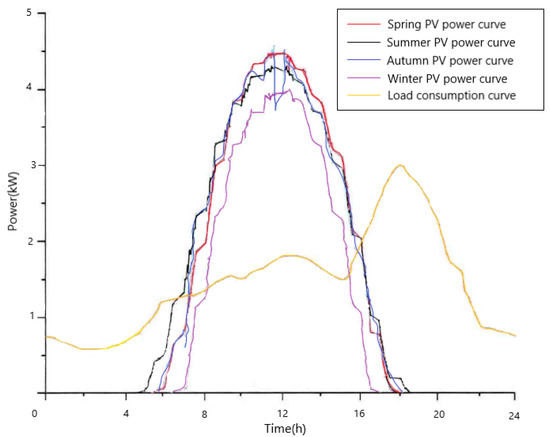
Figure 1.
Photovoltaic generation curve and user electricity curve.
Comparing these curves, it can be seen that there is a consistent period that occurs each day when the PV power generation exceeds user consumption levels. This indicates an excess of PV-generated electricity that cannot be fully utilized by users. Consequently, this surplus electricity is redirected back into the grid, resulting in a reversal of power flow from the end of the distribution line back towards its source. This change in power flow direction within the network leads to voltage elevation [26] along the line. When only a small amount of PV power is fed into the network, it flows into the distribution network so that it can be consumed by other users without PV installations. However, when the PV power volume is substantially larger, the surplus power cannot be consumed, resulting in voltage fluctuations. This study employed PV-ES devices to effectively mitigate these voltage fluctuations, optimize electricity consumption, and maximize the utilization of generated electricity [27].
3. Photovoltaic Electric Spring Principle
Electric spring (ES) is an innovative smart grid technology that has been used to maintain voltage and current stability in weakly regulated or independent grids powered by renewable energy sources. It serves as a demand side management (DSM) solution for voltage and power regulation, enabling the stable control of critical load voltages in the presence of voltage fluctuations originating from new energy sources, ensuring high-quality power for consumers. In Figure 2, the ES device is represented by the circuit in the dashed box. The primary principle relies on the parallel connection of a DC power supply and a capacitor. The control system consists of two pairs of insulated-gate bipolar transistor (IGBT) full bridge inverter circuits and an LC low pass filter. The capacitance and inductance in the filter, represented by Cf and Lf, respectively, are utilized to filter out harmonics.

Figure 2.
Working principle of ES.
The ES was connected to the power grid in series with the NCL and then in parallel with the CL. The ES operates in three modes, which are analogous to the ES elastic deformation modes: balance, extension, and compression. These also correspond to three elements of current operation: stabilization, boost, and buck. The adjustment of the ES’s operation mode is achieved by varying the voltage at both ends of the NCL. This collaboration between the NCL and the ES effectively suppresses bus voltage fluctuations and ensures a stable CL voltage. It is worth noting that voltage instability problems are commonly addressed using battery devices, which stabilize the voltage through the battery’s charging and discharging functions. However, such solutions require high capacitance and expensive batteries, which are not conducive to the economic operation of micro-grids.
In grids characterized by a wide range of voltage fluctuations, achieving a balance between power generation and power consumption involves maintaining the voltage of the CL within a defined range of fluctuations, while transferring the majority of the fluctuations to the NCL. This process is accomplished by controlling the voltage across the ES, thereby modifying the voltage across the NCL in the series circuit. In this way, the NCL can absorb the fluctuations in the circuit and ensure that voltage fluctuations at the CL remain within a stable range.
At present, ES systems mostly rely on DC batteries or direct access to electricity from the power grid for their energy. However, the increasing emphasis on environmental protection has led to a renewed focus on renewable energy sources—including PV power—and ES systems must also take renewability into account [28]. Among the available alternative energy sources, electrical energy from PV cells is particularly appealing, as it is regarded as a natural energy source that is valued for its abundance, cleanliness, and widespread distribution across the Earth. It also serves as a primary factor in all other energy production processes [29]. Integrating PV power with ES, we have developed a new system, the photovoltaic-electric spring (PV-ES) (Figure 3). However, due to the relatively low output generated by PV power, it was initially unable to meet typical power supply demands. Therefore, we have improved the main circuit in the ES by incorporating PV power generation technology, which serves as the power input to the main circuit of the ES. Additionally, the conductance increment method was employed to ensure the MPPT of the PV panel. The PV system and ES system should work together properly so that the system can transmit intermittent PV power to the grid without the need for battery storage, also making the power greener.
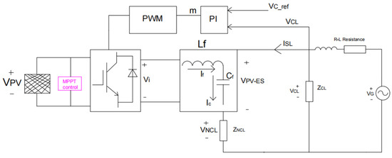
Figure 3.
Working principle of PV-ES.
Firstly, the difference between the reference voltage (VCL_ref) and the actual measured critical load voltage (VCL) is input into PI, and the PI controller transforms the voltage value with less deviation to determine the modulation factor m (Equation (3)). Secondly, the PWM generator is adjusted to generate a high-quality pulse wave at a rated frequency. Then, the output voltage Vi of the half-bridge inverter circuit is generated by the inverter. Finally, the LC output filter is used to generate the PV-ES voltage (VPV-ES) with adjustable amplitude. The PV-ES mathematical model and Vi are as follows:
G(t) is the compensation function and VPWM is the voltage amplitude of the PWM waveform determined. According to the above analysis, the state space equation is used to express PV-ES of the average model:
4. PVES Application Configuration Modeling
Figure 4 illustrates the PV-ES grid simulation system. The grid’s power supply is transmitted to the downstream users via the R-L circuit impedance. The fluctuations generated by the distributed power supply flow into the power supply line through the system connection point. The line features a centralized R-L impedance. The distributed power supply module adopts a three-phase PV grid-connected system and is directly connected to the 220 V grid.

Figure 4.
Application system diagram.
4.1. Grid-Connected System
With the increasing energy demand and environmental pollution problems, DG as a major contributor of renewable energy, has become an important issue for future power development. However, the problem of the randomness and volatility of DG limits its large-scale grid connection. A high volume of PV power generation introduces randomness and uncertainty [30] when connected to a distribution network, leading to various negative effects. These include a reduction in power quality, increased challenges in relay protection, and disruptions to the operation of existing automation equipment. One of the most significant impacts is power back-feeding, which can result in voltage crossing limit problems in PV grid-connected systems. Fortunately, ES technology can be used to mitigate these problems [31].
Through the conduction and closing of power electronic switches, PV [32] inverters play a key role in converting the DC power generated by PV systems into the AC power that meets the grid-connected requirements. The DC-AC PV grid-connected inverter topology model, selected as the PV inverter in this paper, is depicted in Figure 5.
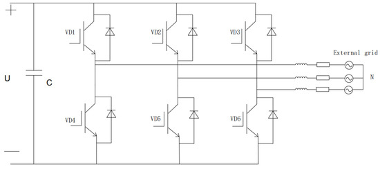
Figure 5.
Photovoltaic grid-connected inverter topology model.
This PV inverter consists of six semiconductor components in the DC/AC link, along with a voltage regulator capacitor C, filter inductor L, and resistor R. For the three-phase stationary coordinate system, we can obtain the following equation:
where i is the inverter three-phase output current; e is the inverter three-phase voltage; u is the external grid three-phase voltage; and R and L are the resistance and inductance of each phase, respectively. After transforming Equation (5) to the synchronous rotating dq coordinate system and performing the Rasch transformation, the frequency domain model of the PV inverter is as follows:
where Uq and Ud are the external voltages of the dq axis; Eq and Ed are the output voltages of the dq axis inverter; Iq and Id are the output currents of the dq axis inverter; and is the synchronous rotational angular frequency. The grid-connected system in this study adopted a single-phase grid connected to a constant current and constant power. Following electricity generation by the PV array, a grid voltage of 380 V was detected, and through the gain module, a constant target current of 10 A for the grid-connected power of 2200 W was maintained. This target current was compared with the actual grid current and the appropriate current was obtained through PI control. The resultant current was then fed back into the inverter to complete the grid connection. The results of the grid-connected voltage and current are shown in Figure 6.

Figure 6.
Grid-connected voltage and current.
Following this event, the output current waveform exhibited a slight jaggedness, and an FFT analysis was performed at the analysis point of 0.4 s (Figure 7). The fundamental frequency was determined to be 50 Hz, with an amplitude current of 31.18 A and a harmonic distortion rate of 1.73%. These results met the requirements for grid connection.

Figure 7.
Grid-connected current FFT analysis.
4.2. Design of the PV-ES Management Strategy
The control strategy of the PV-ES system was based on the fundamental concept of the ES, which aims to stabilize the voltage of the critical load (UCL) and control the UCL phase. Using the current ISL phase flowing through the smart load as the reference phase, the system can control the phase of the power spring output voltage (UES). The goal was to achieve a specific phase relationship between UES and ISL, typically a lag or lead angle of 90°. By controlling this phase angle, the PV-ES system can effectively manage the power supply voltage by either boosting or suppressing it. This control action ensures that the voltage at both ends of the CL remains stabilized at the desired reference value (Uc_ref), with the ultimate objective of providing stable and high-quality power to the power-consuming equipment connected to the CL.
The single-phase ES model can be seen as a two-input, single-output control system [33] in which the critical load voltage UCL is affected by both the output voltage UES and the network-side voltage UG. Managing and implementing effective controls in such a system can be difficult and operationally complex. Therefore, we introduced feed-forward control [34] into the system to simplify the control process. This involved treating the net-side voltage UG of the main circuit as a disturbance signal and incorporating it into the control system for correction. After feed-forward correction, it was reconnected to the system. By compensating for and eliminating these disturbance effects, control complexity is significantly reduced, as the dual input is effectively converted into a single input. Based on these design principles, a block diagram of the closed-loop control flow for a single-phase ES was constructed, transforming it into a single-input, single-output system.
As shown in Figure 8, the transfer function of feed-forward control is Gn(S). Theoretically, the application of feed-forward control can effectively suppress the influence of the network-side voltage UG(S) on the critical load voltage UCL(S), allowing UCL(S) to be solely controlled by the reference voltage. This significantly reduces the complexity of the control in a low-voltage distribution network system [35]. To account for practical considerations such as delay reduction, a small inertia connection was added after G2(S). Td represents the time constant in the first-order inertia link, which is set at half of the control system switching period, Ts. KPWM is the gain of the inverter circuit; Kvf is the negative feed-back coefficient of the system; and Gx(S) is the transfer function of the PI controller. The transfer function of the output voltage UCL(S) of the critical load of the controlled object to the net-side voltage UG(S) can then be deduced as follows:

Figure 8.
Closed-loop control flow chart for electric spring.
By applying feed-forward compensation, the impact of the net-side voltage (UG(S) on the critical load voltage is eliminated, resulting in Equation (7) being equal to zero. The transfer function of the feed-forward compensation link can then be obtained as follows:
After eliminating the influence of UG(S) on the critical load voltage UCL(S), the block diagram of the controlled system can be further simplified (Figure 9a). By introducing transfer functions, the ES control system can likewise be simplified. The system’s open- and closed-loop transfer functions are represented by Equations (9) and (10), respectively:

Figure 9.
(a) Simplified control block diagram of electric spring system; (b) quadratic simplified electric spring control block diagram.
This controlled system is a relatively high-order and complex control system. To reduce the control difficulty and simplify the management process, a constant frequency sine wave signal was added to the input of a stable linear constant system [36]. After the system response process reached completion, the steady-state component of the output remained as a sine signal with the same frequency as the input signal. The amplitude and phase of the output sine wave in this scenario are functions of the input signal frequency. The output signal ratio is represented by A(ω) with the phase difference (ω). The output and input were 50 Hz sinusoidal signals, and the gain of the inverter circuit KPWM contributed to the overall system behavior at the angular frequency, forming a new controlled system with the transfer function G1(S). The frequency response of the simplified system is expressed by Equation (11). The control block diagram is shown in Figure 9b.
Th
Based on the block diagram displayed in Figure 9, a classical control strategy based on a PI controller was proposed for the operation of the PV-ES (Figure 10). This was also based on the PV-ES’s reactive power compensation characteristics. Firstly, the voltage reference value of the CL was set to 220 V. The difference between the CL voltage (UCL) and the grid voltage was then fed into the PI controller, which was used to adjust its output until the amplitude of the sinusoidal modulation signal was reached. The phase of the modulation signal was determined by the current ISL flowing through the smart load, which was obtained using a phase-locked loop (PLL). It is used to compensate for the desired phase relative to the grid. The magnitude of the analog signal corresponds to the variable-width pulse generated by the PWM, and the switching frequency is provided by the PWM to turn on the inverter and reduce harmonics. The transfer function of the PI controller is shown in Equation (12), where Kp and Ki are, respectively, PI controller’s proportional and integral parameters.
Tak
Taking into account whether the actual voltage of the critical load was higher or lower than the voltage reference value, and considering the phase of the π/2 modulation signal, the final control output was calculated by multiplying the amplitude of the modulation wave output of the PI controller by the sine function. The frequency of the sinusoidal modulation signal was found to be consistent with the grid frequency, that is, 50 Hz. The generated modulation signal was then fed into the PWM generator to produce a switching signal that could be used to control the on–off state of the IGBTs in the full bridge inverter circuit.
To ensure stable operation in the PV-ES-integrated system, the bus voltage at the CL access point must be maintained at a specified voltage so that the active power absorbed by the CL remains consistent. According to the law of conservation of energy, voltage fluctuations caused by distributed generation are absorbed by NCL. Therefore, the introduction of PV-ES has the potential to change how electricity is traditionally supplied by enabling the real-time regulation of load energy consumption with the simultaneous generation of new energy.

Figure 10.
PV-ES control circuits.
4.3. ETAP Simulation of PV-ES
We then created a simulation model of a distribution line using ETAP 20.6 software. The model included a 10 kV/220 V distribution transformer connected to an infinity supply (100 MVA grid power) and was connected to a low-voltage consumer via overhead lines and cables. To simulate voltage fluctuations, the taps of the distribution transformer were adjusted, and a simplified version of the PV step-up power spring circuit was simulated by connecting PV modules in parallel with capacitors. The effects of a static VAR compensator (SVC), a static synchronous compensator (STATCOM), and PV-ES on the grid voltage conduction were modeled and analyzed separately.
The grid voltage conduction results (Figure 11) following the implementation of the three compensators are shown in Table 1. The simulation results demonstrate that the utilization of PV-ES not only helps manage low voltage issues within grids but also provides additional support to the grid system overall.
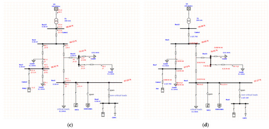
Figure 11.
(a) No compensator access to the grid; (b) PV-ES access to the grid; (c) SVC access to the grid; (d) STACOM access to the grid.

Table 1.
Voltage boosting effect on the grid with the input of compensation devices.
Based on the above analysis, the feasibility and value of the PV-ES model is confirmed. SIMULINK software was also employed to conduct a comprehensive model simulation of the entire low-voltage grid.
5. Case Studies
Using rural household access to a distributed power supply [37] as an example, a simulation was created according to the application system shown in the block diagram of Figure 4. Analysis was then carried out to identify possible improvements that could be achieved by installing PV-ES. In this model, the monthly power consumption of the user is about 120 kW∙h. The simulation was conducted using MATLAB/SIMULINK, and the internal power supply, wiring, and load parameters of the system are shown in Table 2.
Table 2.
System parameters.
The data from Table 2 were used to test the PV-ES simulation model. The power supply was introduced at values within a small range of fluctuations, 0.2~0.4 s, so that they could be compared with fluctuations in the critical load, non-critical load, grid, and PV-ES voltages (Figure 12 and Figure 13). These figures confirm that voltage fluctuations are stabilized when PV-ES is incorporated into the system, and further confirms the effectiveness of the PV-ES configuration and the accuracy of the experimental results.

Figure 12.
Critical load, non-critical load, grid voltage, and PV-ES voltage without PV-ES connection.

Figure 13.
Critical load, non-critical load, grid voltage, and PV-ES voltage connected to PV-ES.
Based on the experimental analysis, it is clear that the introduction of the PV-ES reduced the fluctuations of the PV grid connection in the CL and grid voltages, and resulted in the output of a stable sine wave. The effectiveness of PV-ES was further verified by the simulation. After adjusting the light intensity and temperature of the PV cell to observe its effect on various voltages (CL, NCL), as well as the active power and reactive power of the output, we selected the RMS value of the voltage at both ends of the load for comparison.
Figure 14 shows that boosting the light intensity of the PV cell effectively increased the CL voltage, while changing the temperature had no significant effect on this parameter. Therefore, PV-ES not only ensured that the grid voltage and the CL voltage were maintained at constant levels, but it also impacted voltage boosting, which affects user experience on the load side and effectively solves the voltage fluctuation issues inherent in distributed power supplies.

Figure 14.
(a) Critical load voltage RMS; (b) non-critical load voltage RMS; (c) grid active and reactive power.
6. Conclusions
In the construction of new energy systems in rural areas, PV power generation undoubtedly occupies a leading position. The low-voltage management of rural networks requires systematic work, and the transformation of rural networks through improvements and upgrades promotes the economic development of these remote regions and helps to ensure the normal operation of their power grids. The change in voltage quality after the PV power generation system is connected to the rural distribution network. PV-ES devices can further improve the efficiency of grids in rural areas and optimize energy utilization. This paper introduced a PV-ES device that could be used in conjunction with a three-phase PV grid connection. This system was the basis for a model that simulated energy use by rural users and allowed for the measurement and comparison of voltages under different conditions. The analysis reached the following conclusions:
- PV-ES significantly reduces critical load and grid voltage fluctuations and, to a certain extent, the voltage can be increased;
- PV-ES can also effectively solve low-voltage issues that are common in distributed networks;
- By boosting light intensity, PV-ES runs better;
- PV-ES systems have an important role to play in the future construction and enhancement of rural grids.
Author Contributions
Conceptualization, Z.C. and L.W.; methodology, Z.C., J.S. and G.L.; software, Z.C. and Z.Y.; validation, Z.C., G.L. and D.Z.; formal analysis, J.S.; investigation, Z.Y.; resources, L.W.; data curation, Z.C.; writing—original draft preparation, Z.C.; writing—review and editing, J.S. and L.W.; supervision, L.W.; project administration, L.W.; funding acquisition, L.W. All authors have read and agreed to the published version of the manuscript.
Funding
This paper was supported by the general project of the Liaoning Provincial Department of Education (Z20220514), the teaching reform project of Shenyang Agricultural University (2021-06-01), and the Inner Mongolia Autonomous Region Science and Technology Innovation Guidance Award Fund Project (CXYD2022004).
Data Availability Statement
Data are availability on request from the authors.
Conflicts of Interest
The authors declare no conflict of interest. The funders had no role in the design of the study; in the collection, analyses, or interpretation of data; in the writing of the manuscript; or in the decision to publish the results.
References
- Luo, G.; Guo, Y. Rural electrification in China: A policy and institutional analysis. Renew. Sustain. Energy Rev. 2013, 23, 320–329. [Google Scholar] [CrossRef]
- Cai, T.; Dong, M.; Chen, K.; Gong, T. Methods of participating power spot market bidding and settlement for renewable energy systems. Energy Rep. 2022, 8, 7764–7772. [Google Scholar] [CrossRef]
- Wang, P.; Yu, P.; Huang, L.; Zhang, Y. An integrated technical, economic, and environmental framework for evaluating the rooftop photovoltaic potential of old residential buildings. J. Environ. Manag. 2022, 317, 115296. [Google Scholar] [CrossRef]
- Huang, N.; Zhao, X.; Guo, Y.; Cai, G.; Wang, R. Distribution network expansion planning considering a distributed hydrogen-thermal storage system based on photovoltaic development of the Whole County of China. Energy 2023, 278, 127761. [Google Scholar] [CrossRef]
- Sun, B.; Li, Y.; Zeng, Y.; Chen, J.; Shi, J. Optimization planning method of distributed generation based on steady-state security region of distribution network. Energy Rep. 2022, 8, 4209–4222. [Google Scholar] [CrossRef]
- Yao, E.; Samadi, P.; Wong, V.W.S.; Schober, R. Residential Demand Side Management Under High Penetration of Rooftop Photovoltaic Units. IEEE Trans. Smart Grid 2016, 7, 1597–1608. [Google Scholar] [CrossRef]
- Hui, S.Y.; Lee, C.K.; Wu, F.F. Electric springs—A new smart grid technology. IEEE Trans. Smart Grid 2012, 3, 1552–1561. [Google Scholar] [CrossRef]
- Zheng, Y.; Hill, D.J.; Meng, K.; Hui, S.Y. Critical Bus Voltage Support in Distribution Systems with Electric Springs and Responsibility Sharing. IEEE Trans. Power Syst. 2017, 32, 3584–3593. [Google Scholar] [CrossRef]
- Zheng, Y.; Zhang, C.; Hill, D.J.; Meng, K. Consensus control of electric spring using back-to-back converter for voltage regulation with ultra-high renewable penetration. J. Mod. Power Syst. Clean Energy 2017, 5, 897–907. [Google Scholar] [CrossRef]
- Liang, L.; Hou, Y.; Hill, D.J.; Hui, S.Y.R. Enhancing Resilience of Microgrids with Electric Springs. IEEE Trans. Smart Grid 2018, 9, 2235–2247. [Google Scholar] [CrossRef]
- Yang, Y.; Tan, S.C.; Hui, S.Y. Voltage and frequency control of electric spring based smart loads. In Proceedings of the 2016 IEEE Applied Power Electronics Conference and Exposition (APEC), Long Beach, CA, USA, 20–24 March 2016; pp. 3481–3487. [Google Scholar]
- Soni, J.; Panda, S.K. Electric Spring for Voltage and Power Stability and Power Factor Correction. IEEE Trans. Ind. Appl. 2017, 53, 3871–3879. [Google Scholar] [CrossRef]
- Wang, Q.; Cheng, M.; Jiang, Y. Harmonics Suppression for Critical Loads Using Electric Springs with Current-Source Inverters. IEEE J. Emerg. Sel. Top. Power Electron. 2016, 4, 1362–1369. [Google Scholar] [CrossRef]
- Chen, X.; Hou, Y.; Tan, S.C.; Lee, C.K.; Hui, S.Y.R. Mitigating Voltage and Frequency Fluctuation in Microgrids Using Electric Springs. IEEE Trans. Smart Grid 2015, 6, 508–515. [Google Scholar] [CrossRef]
- Lee, C.K.; Hui, S.Y. Reduction of energy storage requirements in future smart grid using electric springs. IEEE Trans. Smart Grid 2013, 4, 1282–1288. [Google Scholar] [CrossRef]
- Stetz, T.; Marten, F.; Braun, M. Improved Low Voltage Grid-Integration of Photovoltaic Systems in Germany. IEEE Trans. Sustain. Energy 2013, 4, 534–542. [Google Scholar] [CrossRef]
- Saravanan, S.; Ramesh Babu, N. Maximum power point tracking algorithms for photovoltaic system—A review. Renew. Sustain. Energy Rev. 2016, 57, 192–204. [Google Scholar] [CrossRef]
- Naumov, I.V.; Podyachikh, S.V. Green technologies in rural electric powerindustry. IOP Conf. Ser. Earth Environ. Sci. 2021, 808, 012006. [Google Scholar] [CrossRef]
- Hubble, A.H.; Ustun, T.S. Composition, placement, and economics of rural microgrids for ensuring sustainable development. Sustain. Energy Grids Netw. 2018, 13, 1–18. [Google Scholar] [CrossRef]
- Su, Y.; Zhao, C.; Xu, L.; Liu, X. Distributed Generation Application in the Rural Areas of West China. Energy Power Eng. 2013, 5, 167–170. [Google Scholar] [CrossRef]
- Yang, Y.; Li, H.; Aichhorn, A.; Zheng, J.; Greenleaf, M. Sizing Strategy of Distributed Battery Storage System with High Penetration of Photovoltaic for Voltage Regulation and Peak Load Shaving. IEEE Trans. Smart Grid 2014, 5, 982–991. [Google Scholar] [CrossRef]
- Ge, L.; Du, T.; Li, C.; Li, Y.; Yan, J.; Rafiq, M.U. Virtual Collection for Distributed Photovoltaic Data: Challenges, Methodologies, and Applications. Energies 2022, 15, 8783. [Google Scholar] [CrossRef]
- Shi, J.; Lee, W.J.; Liu, Y.; Yang, Y.; Wang, P. Forecasting Power Output of Photovoltaic Systems Based on Weather Classification and Support Vector Machines. IEEE Trans. Ind. Appl. 2012, 48, 1064–1069. [Google Scholar] [CrossRef]
- Wang, W.; Zhang, M. Direct and indirect energy consumption of rural households in China. Nat. Hazards 2015, 79, 1693–1705. [Google Scholar] [CrossRef]
- Zhang, Y.; Beaudin, M.; Taheri, R.; Zareipour, H.; Wood, D. Day-Ahead Power Output Forecasting for Small-Scale Solar Photovoltaic Electricity Generators. IEEE Trans. Smart Grid 2015, 6, 2253–2262. [Google Scholar] [CrossRef]
- Kabir, M.N.; Mishra, Y.; Bansal, R.C. Probabilistic load flow for distribution systems with uncertain PV generation. Appl. Energy 2016, 163, 343–351. [Google Scholar] [CrossRef]
- Kanjiya, P.; Khadkikar, V. Enhancing power quality and stability of future smart grid with intermittent renewable energy sources using electric springs. In Proceedings of the 2013 International Conference on Renewable Energy Research and Applications (ICRERA), Madrid, Spain, 20–23 October 2013; pp. 918–922. [Google Scholar]
- Cherukuri, S.H.C.; Saravanan, B.; Swarup, K. Analysis of DC Electric Springs in the Micro Grid System Consisting of Fluctuating Energy Sources. Energy Procedia 2016, 90, 114–123. [Google Scholar] [CrossRef]
- de Brito, M.A.G.; Galotto, L.; Sampaio, L.P.; Melo, G.A.; Canesin, C.A. Evaluation of the Main MPPT Techniques for Photovoltaic Applications. IEEE Trans. Ind. Electron. 2013, 60, 1156–1167. [Google Scholar] [CrossRef]
- Jiang, S.; Wan, C.; Chen, C.; Cao, E.; Song, Y. Distributed photovoltaic generation in the electricity market: Status, mode and strategy. CSEE J. Power Energy Syst. 2018, 4, 263–272. [Google Scholar] [CrossRef]
- Lee, C.K.; Chaudhuri, B.; Hui, S.Y. Hardware and Control Implementation of Electric Springs for Stabilizing Future Smart Grid With Intermittent Renewable Energy Sources. IEEE J. Emerg. Sel. Top. Power Electron. 2013, 1, 18–27. [Google Scholar] [CrossRef]
- Mohammed, A.Y.; Mohammed, F.I.; Ibrahim, M.Y. Grid connected Photovoltaic system. In Proceedings of the 2017 International Conference on Communication, Control, Computing and Electronics Engineering (ICCCCEE), Khartoum, Sudan, 16–18 January 2017; pp. 1–5. [Google Scholar]
- Solanki, M.D.; Joshi, S.K. Control of Electric Spring: A Lead–Lag Compensated Approach. J. Inst. Eng. India Ser. B 2021, 102, 469–476. [Google Scholar] [CrossRef]
- Nair, P.; Deepa, K. Feed-Forward Control Algorithm for Hybrid Energy Systems. Procedia Technol. 2015, 21, 575–580. [Google Scholar] [CrossRef]
- Zhang, D.; Li, J.; Hui, D. Coordinated control for voltage regulation of distribution network voltage regulation by distributed energy storage systems. Prot. Control Mod. Power Syst. 2018, 3, 3. [Google Scholar] [CrossRef]
- Lima, F.V.; Georgakis, C. Input–output operability of control systems: The steady-state case. J. Process Control 2010, 20, 769–776. [Google Scholar] [CrossRef]
- Chakravorty, D.; Guo, J.; Chaudhuri, B.; Hui, S.Y.R. Small Signal Stability Analysis of Distribution Networks with Electric Springs. IEEE Trans. Smart Grid 2019, 10, 1543–1552. [Google Scholar] [CrossRef]
Disclaimer/Publisher’s Note: The statements, opinions and data contained in all publications are solely those of the individual author(s) and contributor(s) and not of MDPI and/or the editor(s). MDPI and/or the editor(s) disclaim responsibility for any injury to people or property resulting from any ideas, methods, instructions or products referred to in the content. |
© 2023 by the authors. Licensee MDPI, Basel, Switzerland. This article is an open access article distributed under the terms and conditions of the Creative Commons Attribution (CC BY) license (https://creativecommons.org/licenses/by/4.0/).