Article

Active Disturbance Rejection Control of Five-Phase Motor Based on Parameter Setting of Genetic Algorithm

School of Electrical Engineering, Naval University of Engineering, Jiefang Road 717, Wuhan 430030, China
*
Author to whom correspondence should be addressed.
Processes 2023, 11(6), 1712; https://doi.org/10.3390/pr11061712
Submission received: 18 May 2023 / Revised: 29 May 2023 / Accepted: 1 June 2023 / Published: 3 June 2023
(This article belongs to the Special Issue Adaptive Control: Design and Analysis)

Abstract

:
Five-phase induction motors have the characteristics of high torque density, low torque ripple, and flexible control, making them suitable for medium- and low-voltage power supply situations. However, with the expansion of application scenarios, five-phase motors need to cope with increasingly complex operating conditions. Five-phase motors for propeller propulsion will face various complex sea conditions during actual use, and five-phase motors for electric vehicles will also face various complex road conditions and operating requirements during use. Therefore, as a propulsion motor, its speed control system must have strong robustness and anti-disturbance performance. The use of traditional PI algorithms has problems, such as poor adaptability and inability to adapt to various complex working conditions, but the use of an active disturbance rejection controller (ADRC) can effectively solve these problems. However, due to the significant coupling between the variables of induction motors and the large number of parameters in the ADRC, tuning the parameters of the ADRC is complex. Traditional empirical tuning methods can only obtain a rough range of parameter values and may have significant errors. Therefore, this paper uses ADRC based on genetic algorithm(GAADRC) to tune the parameters of the control and design an objective function based on multi-objective optimization. The parameters to be adjusted were obtained through multiple iterations. The simulation and experimental results indicate that GAADRC has lower startup overshoot, faster adjustment time, and lower load/unload speed changes compared to the empirically tuned PI controller and ADRC. Meanwhile, using a genetic algorithm for motor ADRC parameter tuning can obtain optimal control parameters while the control parameter range is completely uncertain; therefore, the method proposed in this paper has strong practical value.

1. Introduction

The ADRC was first proposed by Han Jingqing in 1990s, which is a kind of exploration based on a PID controller and a nonlinear controller for uncertain systems [1]. An ADRC can estimate and compensate external interference and parameter changes, so it does not need an accurately controlled object model, which means that the design of an ADRC system is inherently independent from the controlled system model and its parameters [2,3]. In the development process of ADRC technology, the scholar Gao Zhiqiang tried to linearize and discretize nonlinear controllers [4], which solved the difficult problem of proving controller stability and simplified the process of controller parameter tuning. Since an ADRC was proposed, several fields have started to make beneficial attempts to utilize it, and ADRCs have gradually been applied in many fields, including for a boiler combustion system, generator excitation system, magnetic levitation system, platform stability system, aircraft attitude control system, DC power transmission system, and motor control system [5,6,7,8,9,10].
However, compared with the traditional PI controller, the ADRC has more parameters, a more complex algorithm structure, and greater coupling degree. In order to solve this problem, there are many studies on how to adjust the parameters of an ADRC. At present, there are roughly two ways to set ADRC parameters. One is to use the traditional empirical setting method, whose objects are mostly simplified linear ADRCs or simply improved controllers based on it. The other is to automatically obtain the parameters of the controller by means of various intelligent optimization algorithms. This method is more universal. It can not only adjust the parameters of a linear ADRC but also solve the complex coupling problem between various improved nonlinear ADRC parameters.
The empirical setting method is mainly based on the transfer function of the controller and the controlled object. For a linear ADRC, the transfer function of the controller can be written directly in most cases. By analyzing the characteristics of the transfer function, the parameters required by the controller can be obtained directly.
Meanwhile, there are various types of intelligent optimization algorithms. As they do not require specific physical meanings, most of them only consider the actual output of the system based on certain inputs, and do not pay attention to the specific coupling relationship between various parameters [11]. Therefore, the steps of deriving and simplifying complex system transfer functions are omitted, which saves the time required to adjust controller parameters and has great universality. In recent years, many intelligent optimization algorithms have been applied to controller parameter settings, including genetic algorithms, the ant colony algorithm, chaotic whale algorithm, simulated annealing algorithm, immune algorithm, and differential evolution algorithm [12,13,14,15,16,17,18,19,20,21].
The general principles of various parameter tuning methods are similar. Firstly, consider the tuned parameters as inputs and select multiple sets of initialization parameters within a certain range to initialize the input parameters. Secondly, considering the actual needs of the control system, appropriate objective functions are formulated to input various initialization parameters into the system to generate output results. Finally, perform backtracking calculations based on the values of the objective function obtained from different initialization parameters to obtain new input parameters. Repeat the iteration to a fixed algebra or until the algorithm converges to a smaller value to achieve the expected output effect.
A genetic algorithm is a kind of intelligent optimization algorithm which is widely used. It is a computational model simulating natural selection and genetic mechanisms in Darwinian biological evolution. It has been previously used for setting parameters of active disturbance rejection controllers in motors. In order to realize the maximum power tracking of a photovoltaic generating set, N Elmouhi et al. [14] used an ADRC to control a PWM rectifier on the output side of doubly-fed induction generator. In order to achieve better tracking performance, a genetic algorithm was used to adjust ADRC parameters. Yang Zebin’s team [15] proposed an improved genetic algorithm based on a particle swarm optimization algorithm to solve the problem that ADRC parameters of bearingless induction motor are difficult to set, which improved the speed regulation performance of the motor during starting, loading, and unloading. Compared with other intelligent optimization algorithms, the principle of a genetic algorithm is simple and easy to implement. Because there is no need to design complex neural networks, the genetic algorithm does not require much computing power and can obtain the optimization results in a short time.
It can be seen that ADRCs have been widely used in all fields and have been extensively studied in the field of motor control. In addition, in order to solve various practical problems in the process of motor operation, a variety of new ADRC structures have appeared, but each new control structure has a certain range of application. Solving some of the most prominent problems also creates other problems.
There are many parameters to be set in an ADRC, and the parameter setting based on experience not only costs a lot of time but also cannot guarantee the optimal parameters. In order to solve the problem that too many parameters are difficult to set in an ADRC, there are a variety of off-line parameter-setting algorithms, among which a genetic algorithm is a more widely used one, and its principle is simple and easy to implement. However, there is a lack of application in the control field of five-phase motor ADRC. Therefore, this paper proposes using a genetic algorithm to tune the parameters of a five-phase-motor ADRC. Compared with other optimization algorithms in [14,15], the genetic algorithm proposed in this paper has the characteristics of clear tuning objectives and accurate tuning parameters, and the adjusted ADRC has strong robustness. The algorithm proposed in this article not only saves time in parameter tuning but also obtains the optimal control parameters, which has great application scenarios and practical value.

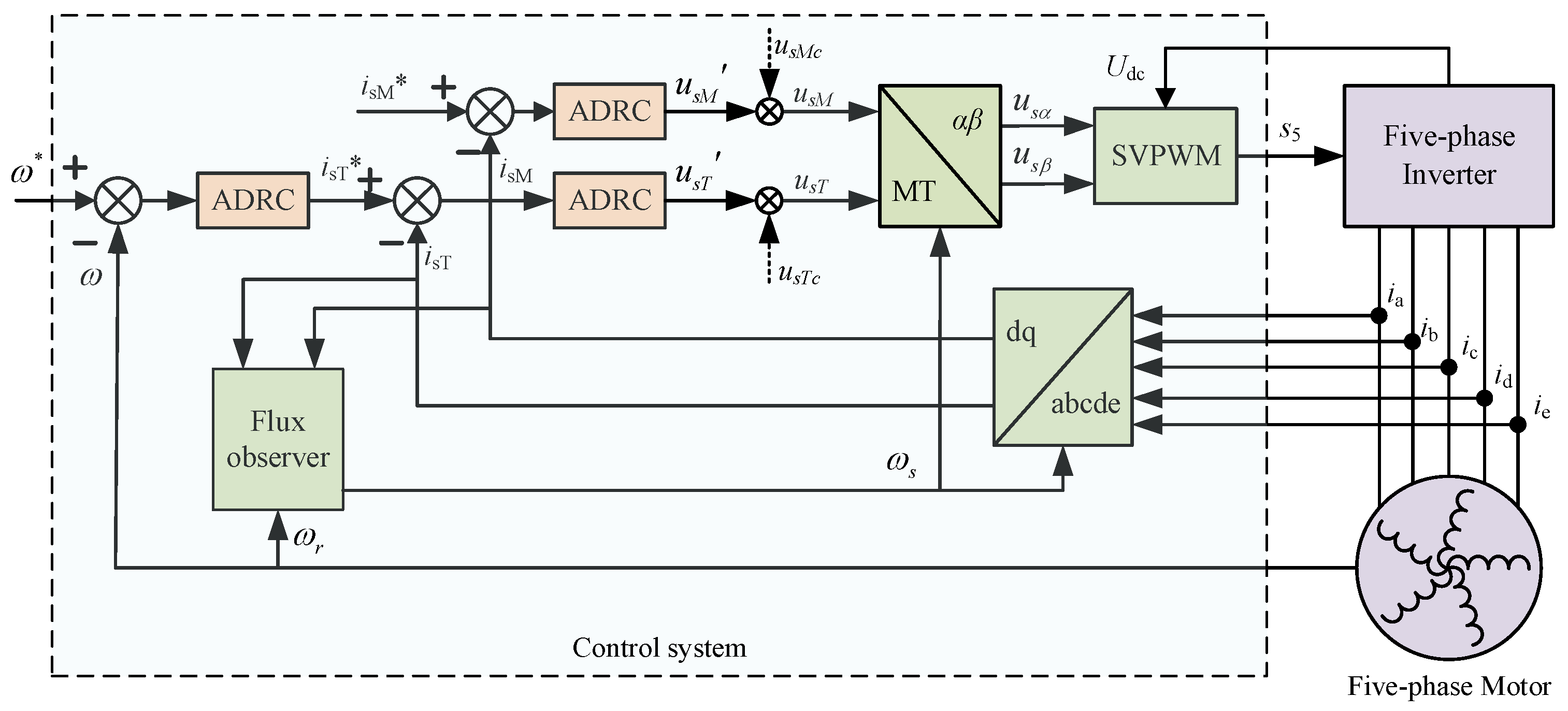
2. Analysis of ADRC for Five-Phase Induction Motor

2.1. Principle of Five-Phase Motor

By performing a Clark transformation on the voltage and flux equations in the basic subspace of a five-phase induction motor, the voltage and flux equations in the stationary coordinate system of the five-phase induction motor can be obtained, as shown below.
[ u s α u s β u r α u r β ] = [ R s 0 0 0 0 R s 0 0 0 0 R r 0 0 0 0 R r ] [ i s α i s β i r α i r β ] + d d t [ ψ s α ψ s β ψ r α ψ r β ] + [ 0 0 ω r ψ s β ω r ψ s α ]
[ ψ s α ψ s β ψ r α ψ r β ] = [ L s d 0 L m d 0 0 L s d 0 L m d L m d 0 L r d 0 0 L m d 0 L r d ] [ i s α i s β i r α i r β ]
where R s and R r represent the stator and rotor resistance, respectively, L s d and L r d denote the equivalent self-inductance of the stator winding and rotor winding, respectively, and L m d denotes the equivalent mutual inductance of the stator and rotor windings. u s α , i s α ,   and   ψ s α represent stator α-axis voltage, current, and flux linkage, respectively, and u s β , i s β ,   and   ψ s β represent stator β -axis voltage, current, and flux linkage, respectively.
The mechanical equation of the five-phase motor is shown below.
T e = n p L m d ( i s β i r α i s α i r β )
where n p represents the number of motor poles, and T e represents motor electromagnetic torque.
The expression for the mechanical motion of the motor is shown below.
T e T L = J n p d ω r d t
where T L represent motor load torque, J represents the motor rotational inertia, and ω r represents motor angular velocity.
Based on the above Equations (1) to (4), the mathematical model of a five-phase motor can be constructed, and the motor parameters are shown in Table 1.

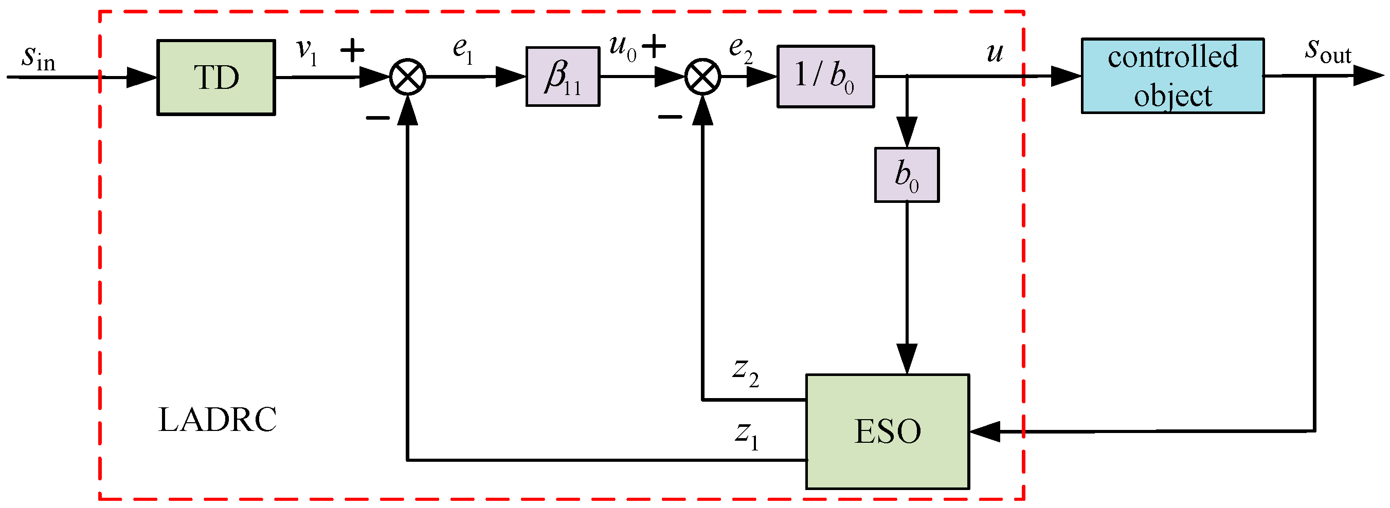
2.2. Principle of Linear ADRC

The basic schematic diagram of a linear ADRC system is shown in Figure 1. It can be seen that an ADRC mainly consists of a tracking differentiator (TD) and an extended state observer (ESO).
As the most important part of an ADRC, an ESO is mainly responsible for filtering the output value of the system and observing the disturbance quantity in it [22]. Its input has two time-varying parameters, including the output of the controlled object and the output of the controller. The block diagram of the structure is shown in Figure 1, and the basic expression of a linear ESO is shown below.
{ e = s o u t z 1 z 1 ( k + 1 ) = z 1 ( k ) + h ( z 2 ( k ) + b 0 u + β 1 e ) z 2 ( k + 1 ) = z 2 ( k ) + h β 2 e
where z 1 is the observed value of s o u t , z 2 is the perturbation observation quantity of s o u t , e is the error between the observed value output by the system and the real value, u is the output value of ESO, h is the discrete time constant, and b 0 , β 1 , β 2 are proportional constants.
Since the motor speed is a slowly rising quantity and cannot change in the actual system, the design of the ADRCs motor speed loop needs to consider a suitable given curve. With the goal of setting the speed value v s , the design of the TD is shown below:
{ e = z 1 v * f h = f h a n ( e , z 2 , r 0 , h ) z 1 ( k + 1 ) = z 1 ( k ) + h z 2 ( k ) z 2 ( k + 1 ) = z 2 ( k ) + h f h
where v * represents motor output speed, and f h a n ( e , z 2 , r 0 , h ) is called the most rapid control synthesis function, whose algorithm expression is shown below:
{ d = r 0 h d 0 = h d y = e + h z 2 a 0 = d 2 + 8 r 0 | y | a = { z 2 + a 0 d 2 s i g n ( y ) ,   | y | > d 0 z 2 + y h ,   | y | d 0 f h a n = { r 0 s i g n ( a ) ,   | a | > d r 0 a d ,   | a | d
The structure block diagram of a five-phase induction motor vector control system based on an ADRC is shown in Figure 2.

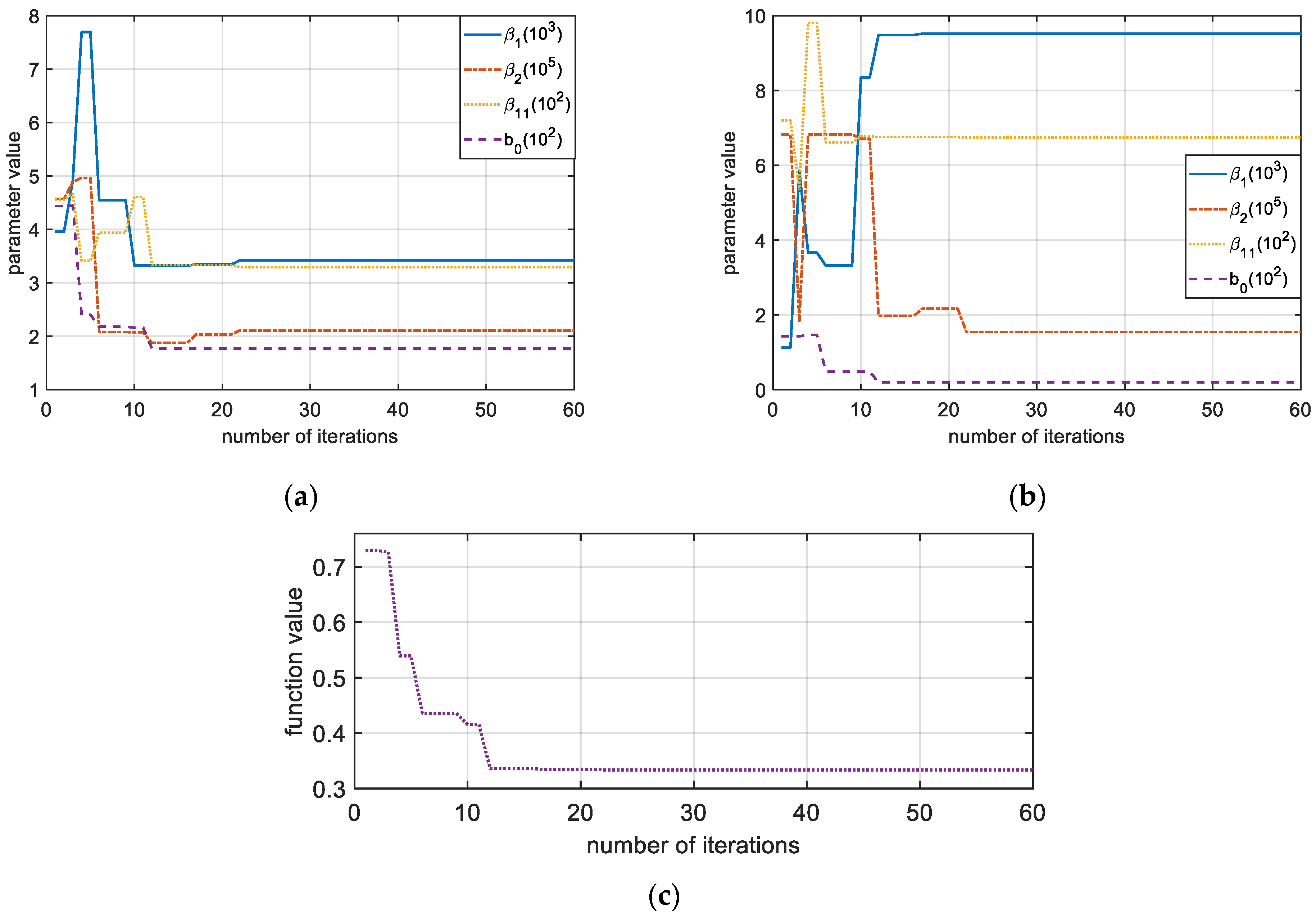
3. ADRC Parameter Optimization Based on GA

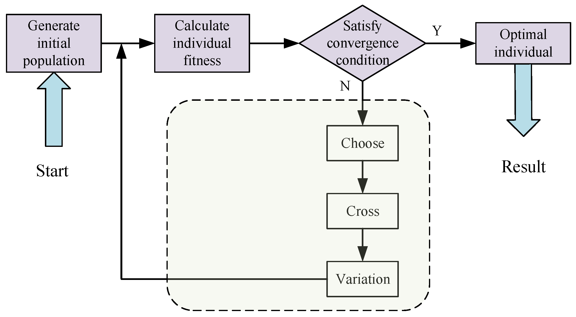
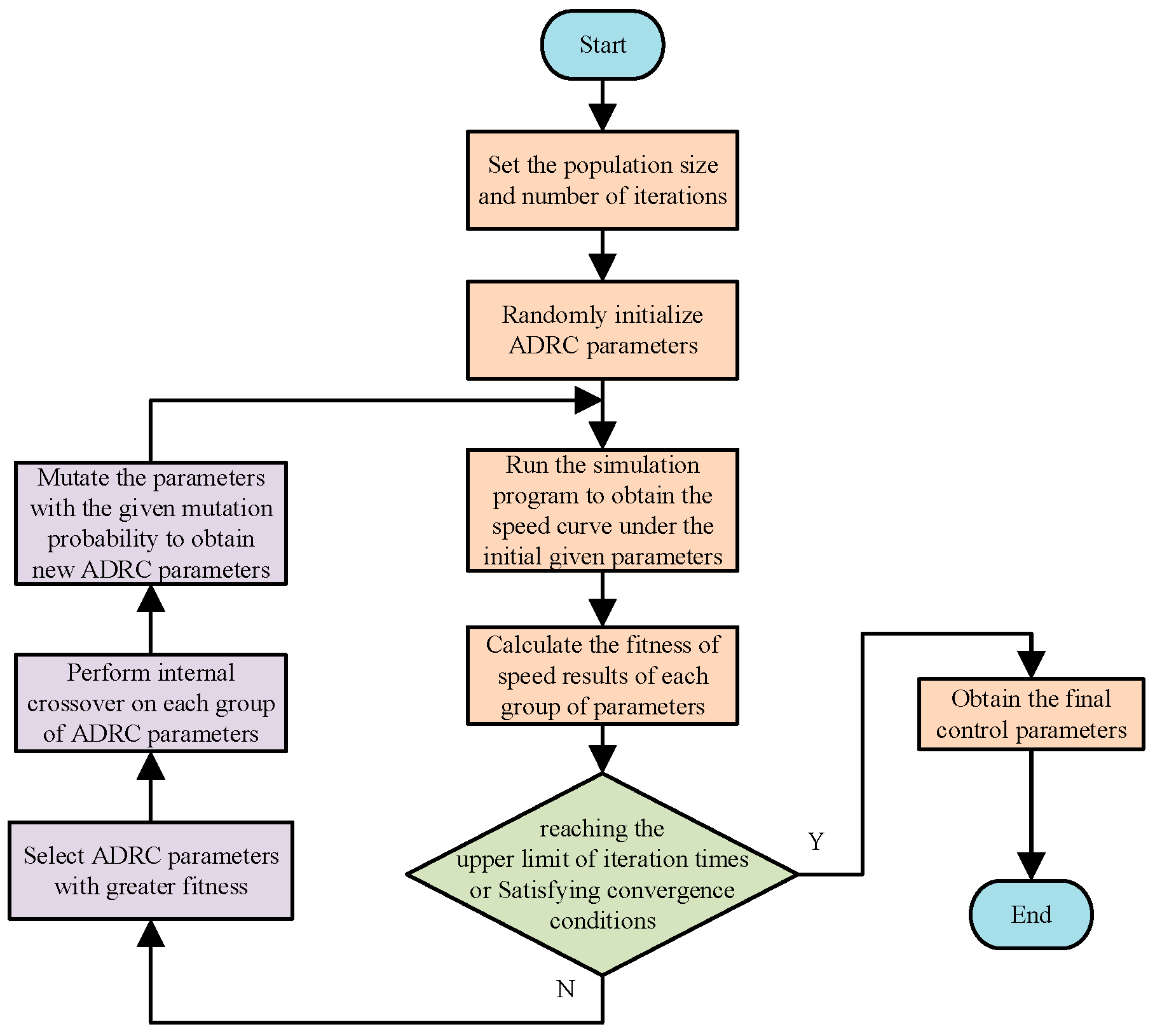
3.1. Basic Principles of Genetic Algorithm

The basic flowchart of a genetic algorithm is shown in Figure 3.
(1)
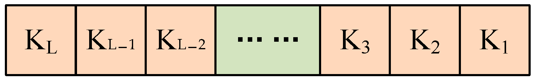
Initialize design parameters
In a linear ADRC, there are eight parameters to be set, including the current loop and speed loop parameters β 1 , β 2 ,     β 11 ,   and   b 0 . The first step is to initialize the parameters to be determined by using random parameter initialization to generate the initial generation parameters.
In order to facilitate the following steps of crossover and mutation, it is necessary to use binary encoding to generate random numbers r. Suppose the length of a single random number string is L, and the string digit from low to high is K i , and its value is 0 or 1, as shown in Figure 4, then the random number generated is as follows:
r = i = 1 L 2 i 1 K i 2 L
Then, the initialized random matrix is generated as follows:
R i n i = [ r 1 , 1 r 1 , 2 r 1 , 8 r 2 , 1 r 2 , 2 r 2 , 8 r G , 1 r G , 2 r G , 8 ]
where G represents population size.
The selection of population size is not as large as possible. A larger population size means that the scale of computation is larger, and the time required to run the algorithm increases. However, a smaller population size may cause the optimal value interval to be missed, especially in the face of multivariate optimization, making the system more likely to miss the best combination. In addition to determining the population size, it is also necessary to set the maximum evolutionary algebra, and the purpose of designing the maximum evolutionary algebra is to prevent the system from being unable to stop running because it has never converged, so that the system automatically stops running after running to a certain algebra without relying on whether the objective function is within the constraints.
(2)
Objective function determination
The most important thing in the optimization of motor controller parameters using genetic algorithms is to determine the objective function. In the field of motor control, the pursuit is stable and fast control performance. “Stability” is reflected in whether the response curve can eventually converge, “accurate” is reflected in whether the final stable value of the response curve reaches a given, and “fast” is reflected in the rise time and adjustment time. To determine the objective function of motor control, the most important thing is to find the appropriate expression that reflects the performance of motor control.
In the operating condition of a no-load start of the motor, the dynamic response time and overshoot of the system need to be considered. When the motor is running under the operating condition of sudden load reduction, it is necessary to consider the maximum increase and decrease in the speed and the adjustment time required when the motor speed returns to the steady state.
In addition, it is also necessary to consider the operating conditions of motor divergence, and if the motor operation is unstable or even divergent, the individual’s fitness can be reduced to 0 by setting a penalty factor, and the individual is not selected in the process of producing parents in the next step.
(3)
Selection crossing and mutation
Using tournament selection, single-point crossing, and uniform mutation as setting mode. On the basis of the uniform mutation, the following improvements have been made. In the early stage of iteration, due to the existence of multiple sets of initialization parameters, the early stage of the mutation has probability to maintain a relatively low value. In the later stage of the iteration, the parameters gradually converge. In order to ensure that the parameters jump out of the local optimal limit, set the later variation probability to a larger value, and the mutation probability p m is expressed in the form of a piecewise function as follows:
p m = { 5 % N < 20 10 % 20 < N < 30 20 % 30 < N < 40 35 % 40 < N < 50 50 % 50 < N < 60
where N represents iterations.
According to the above algorithm, the flowchart of ADRC parameter settings based on genetic algorithm can be obtained as shown in Figure 5.

3.2. Parameter Setting Process Based on Genetic Algorithm

The optimization process of ADRC parameters based on genetic algorithms is divided into three steps:
(1)
The control parameters of the current-loop ADRC and the speed-loop ADRC are roughly adjusted based on the dynamic energy of the speed.
(2)
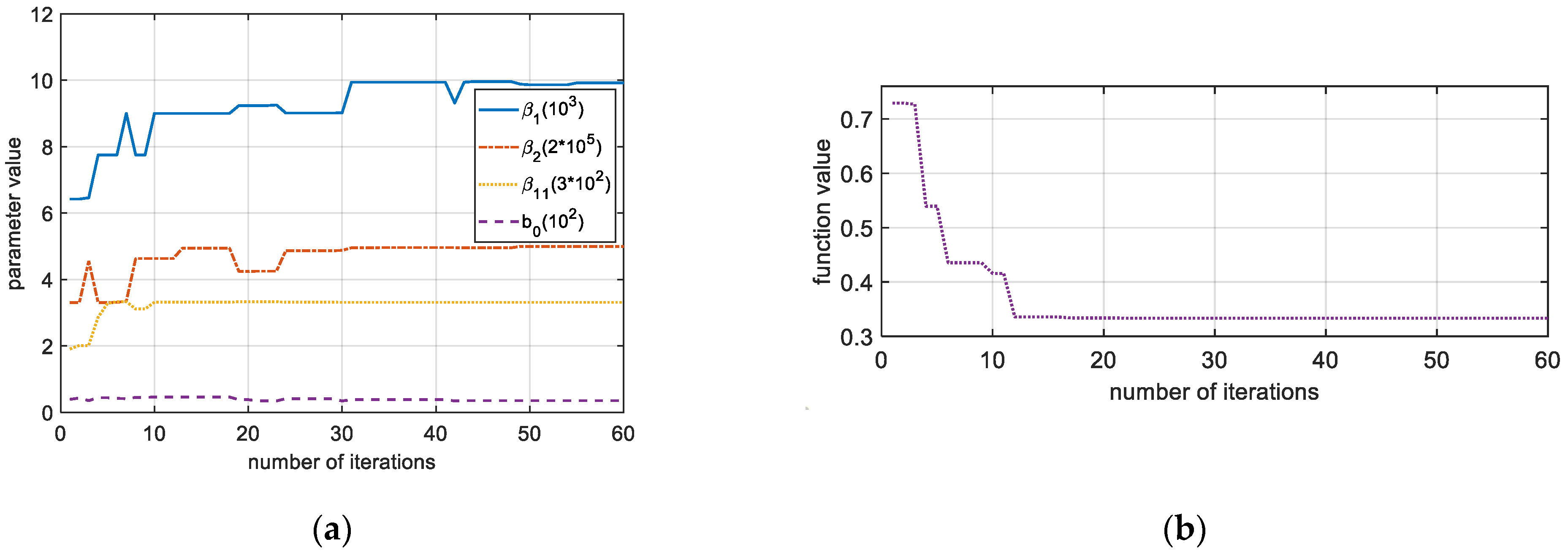
Keep the ADRC parameters of the speed loop obtained in the first step unchanged, take the dynamic tracking performance of the current loop as the optimization objective, and obtain the optimized ADRC parameters of the current loop.
(3)
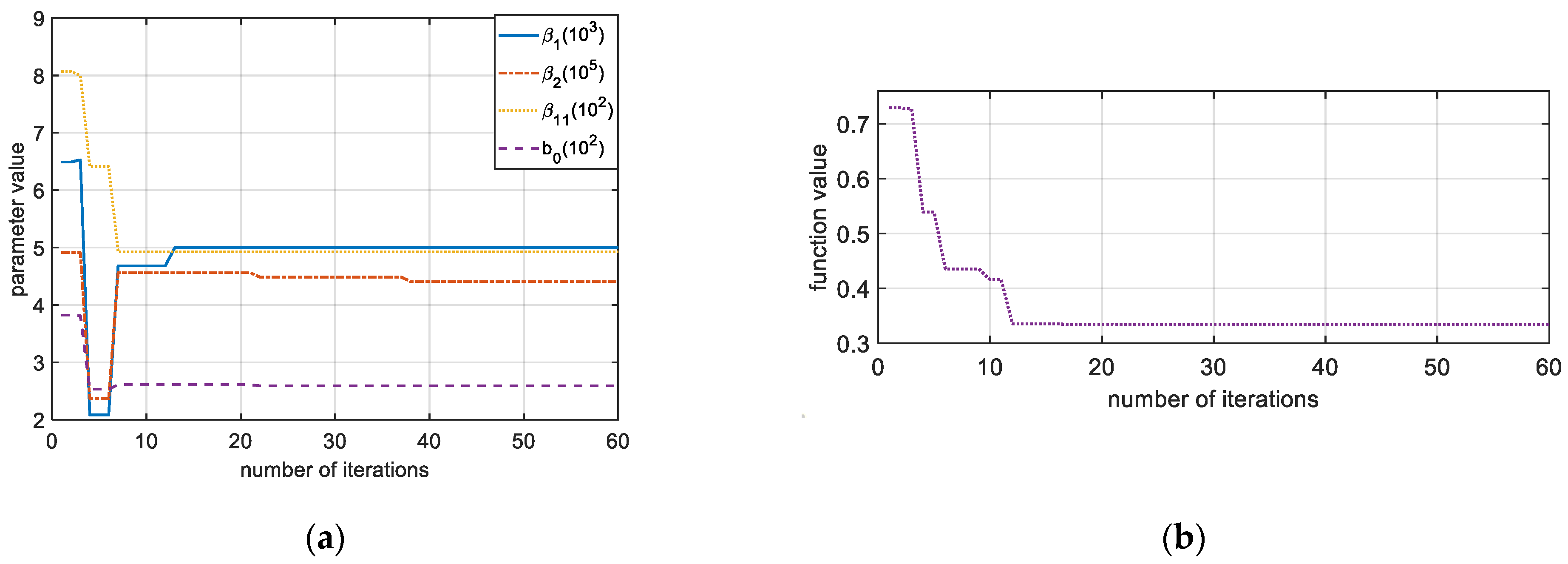
Keep the ADRC parameters of the current loop obtained in step 2 unchanged, and then obtain the optimized ADRC parameters of the speed loop by taking the speed dynamic energy as the optimization objective.
The first step is to set the control parameters of the current loop and the speed loop at the same time, and the design objective function is shown as follows:
f g 1 = p 1 t = 0.7 0.72 ( s t 1000 ) 2000 + p 2 ( max s t 1000 ) + p 3 t = 2 2.02 ( s t 1000 ) 2000 + p 4 [ max s t min s t ] t = 1.4 t = 1.8 + p 5 t = 3.5 3.6 ( s t 800 ) 10000
where s t represents the motor speed at time t, and p 1 ~ p 5 , respectively, represent the reference weights of five target values: no-load start time, no-load start overshooting, loading adjustment time, loading speed drop, and on-load speed regulation time.
The simulation step is set to 10 us, so the number of data points within 0.02 s is 2000. After running the iterative algorithm 60 times, the parameter optimization curve and the change curve of the objective function value are obtained, as shown in Figure 6. It can be seen from the figure that the objective function value of the system tends to be stable after the iteration reaches 22 generations, and the stable value is 0.3335.
The second step is to keep the parameters of the speed-loop ADRC unchanged and only set the parameters of the current-loop ADRC. The design objective function is shown as follows.
f g 2 = p 1 t = 0 4 ( i s m _ t * i s m _ t ) + p 2 t = 0 4 ( i s t _ t * i s t _ t )
where i s m _ t * and i s t _ t * represent the excitation current and torque current set at time t, respectively, and i s m _ t and i s t _ t represent the excitation current and torque current set at time t, respectively.
After running the iterative algorithm 60 times, the parameter optimization curve and the change curve of the objective function value are obtained, as shown in Figure 7. It can be seen from the figure that the objective function value of the system tends to be stable after iteration reaches 55 generations, and the stable value is 0.02216.
In the third step, the parameters of the current-loop ADRC were kept unchanged, and only the parameters of the speed-loop ADRC were set. The designed objective function was consistent with that of the first step, and the parameter optimization curve and the change curve of the objective function value were obtained, as shown in Figure 8. According to the change curve of the objective function, the value of the objective function in the first generation was 0.3597, which is slightly higher than the stable value of the objective function after the whole setting of the step. It becomes stable at 0.3303 after the 38th generation. The setting result of step 1 is optimized to achieve a more optimized control objective.
The parameter changes in the process of motor ADRC system parameter setting through three steps are shown in Figure 6, Figure 7 and Figure 8, and the optimized ADRC parameters are shown in Table 2 below.

4. Simulation and Experimental Analysis

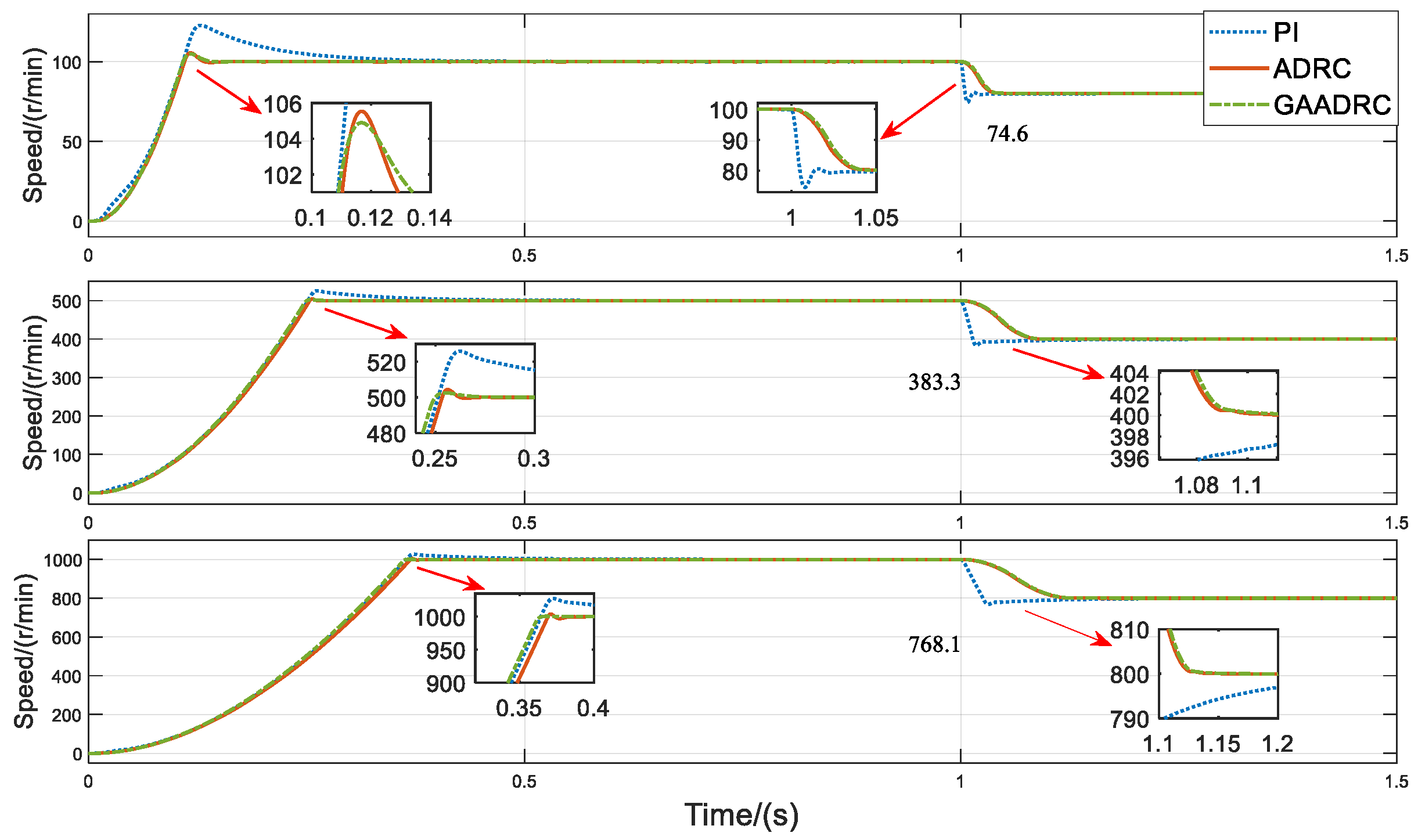
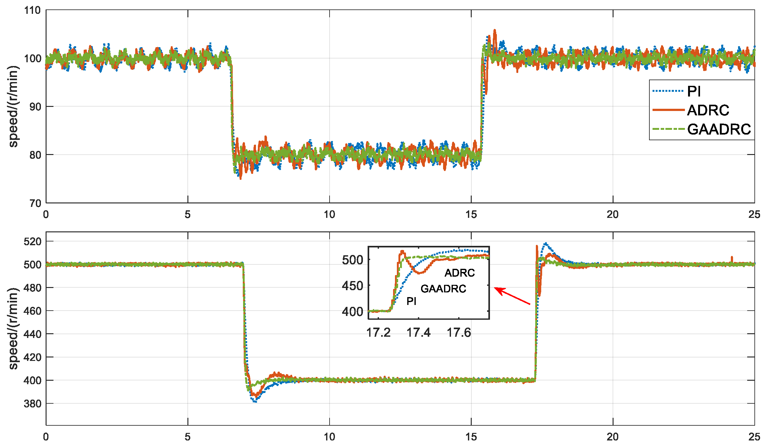
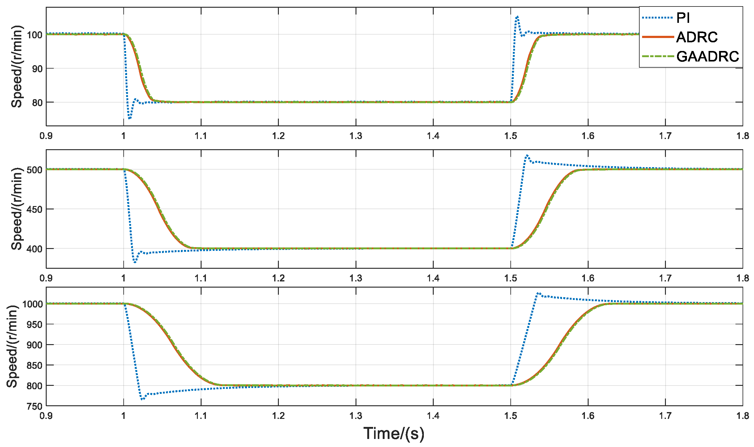
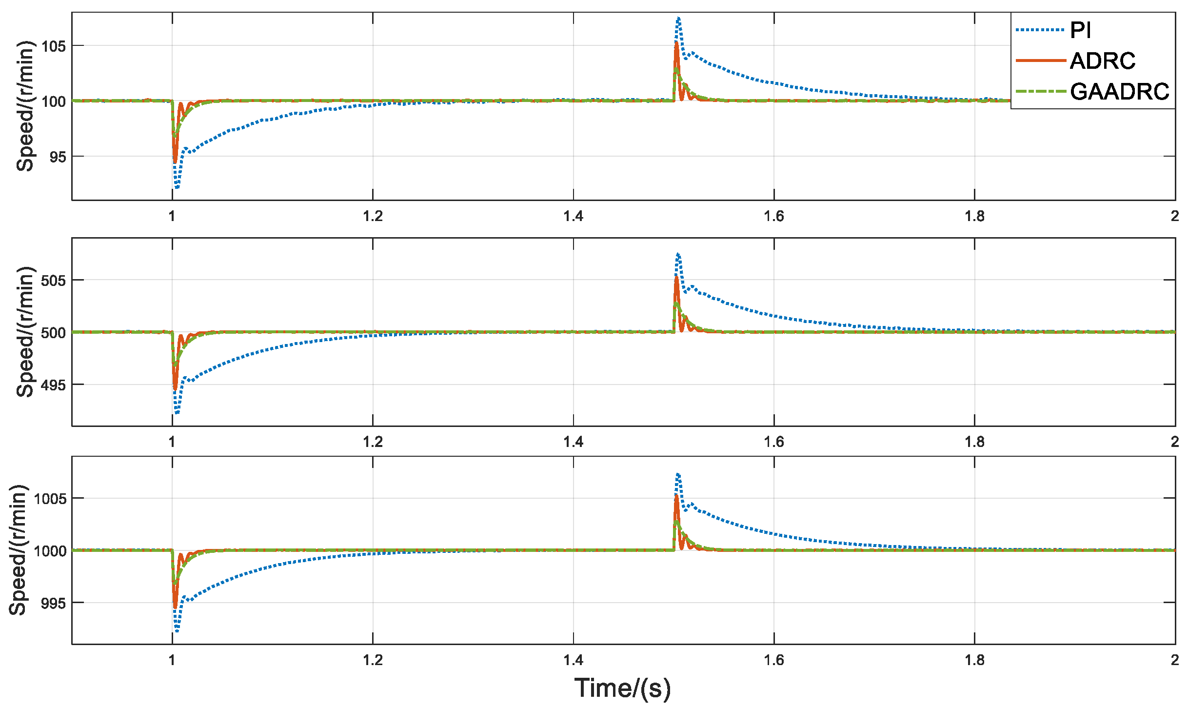
4.1. Analysis of Simulation Results

To verify the performance of an GAADRC, traditional empirical tuning methods can be used to obtain the parameters of an ADRC and PI controller [23]. The PI parameters of the current loop are K p _ c u r = 2.221   and   K i _ c u r = 258.595 , respectively, and the PI parameters of the voltage loop are K p _ v o l = 0.229   and   K i _ v o l = 0.8814 , respectively.
A PI controller and ADRCs and GAADRCs were used to simulate and verify the motor speed regulation performance, and the motor speed regulation performance was analyzed under no-load acceleration and deceleration, as well as acceleration and deceleration under load and load reduction.
Firstly, the motor is started at the given speeds of 100 r/min, 500 r/min, and 1000 r/min and decelerated to 80 r/min, 400 r/min, and 800 r/min, respectively, in the no-load steady state. At this time, the comparison of PI, ADRC, and GAADRC speed waveforms is shown in Figure 9.
The comparison of overshoot during startup and deceleration in Figure 9 is summarized as shown in Table 3. It can be seen that during startup, the overshoot of the PI controller and ADRC decreases with the increase in the given speed, but the overshoot of the ADRC is significantly lower than that of the PI controller, while the overshoot of the GAADRC decreases on the basis of the ADRC. In the deceleration process, the active disturbance rejection controller can achieve low speed overshoot, while the PI controller has large overshoot under different speed control conditions. As can be seen from the adjustment time shown in the enlarged details, the adjustment time of the GAADRC is the fastest, followed by the ADRC, and the PI controller is the slowest. In the deceleration process, when decelerating to 80 r/min, the adjustment time of the PI controller is less than that of the ADRC and GAADRC; when decelerating to 400 r/min and 800 r/min, the adjustment time of the PI controller is greater than that of the ADRC and GAADRC. Due to the influence of TD, the adjustment time of the ADRC and GAADRC in the deceleration process is not much different.
Considering the performance of the on-load speed regulation of the motor in different speed ranges, the motor is set to run with a load of 6 N·m, and the comparison of the PI controller, ADRC, and GAADRC speed waveforms under on-load speed regulations is shown in Figure 10. As can be seen from the figure, there is a large overshoot in the PI controller during acceleration and deceleration while with load. In different speed control ranges from low speed to high speed, the overshoot in the deceleration process is 6.31%, 4.33%, and 4.36%, respectively, and in the acceleration process, the overshoot is 5.36%, 3.51%, and 2.64%, respectively. There is no obvious overshoot between the ADRC and GAADRC, and there is little difference in dynamic performance between them due to the influence of the speed-ring tracking differentiator (TD).
Considering the speed regulation performance of the motor when the load is abruptly increased and reduced at different steady speeds, when the motor starts with no load and reaches stability, 6 N·m load is added for 1 s, and the load is removed for 1.5 s. The comparison of the speed waveform under the condition of abruptly increased and decreased loads is shown in Figure 11. As can be seen from the figure, under different steady-state speed conditions, the same load is added and decreased abruptly, and the amplitude of speed change basically remains unchanged. The PI control speed drop is 8 r/min, the ADRC speed drop is 5.5 r/min, and the GAADRC speed drop is 3.2 r/min. When the load is abruptly discharged, the PI control speed is raised to 7.5 r/min, the ADRC speed is raised to 5.2 r/min, and the GAADRC speed is raised to 2.9 r/min. Compared with the PI controller, the speed overshoot of the ADRC is reduced by 30%. Compared with the ADRC, the overshoot of the GAADRC speed is smaller, reduced by more than 40%, and the speed regulation process is smoother.

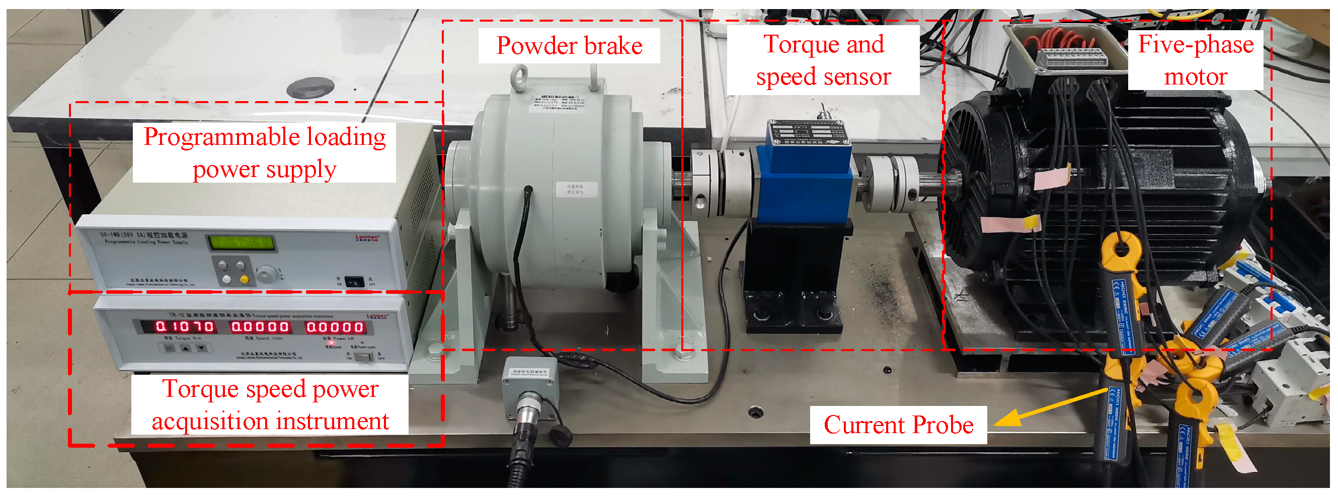
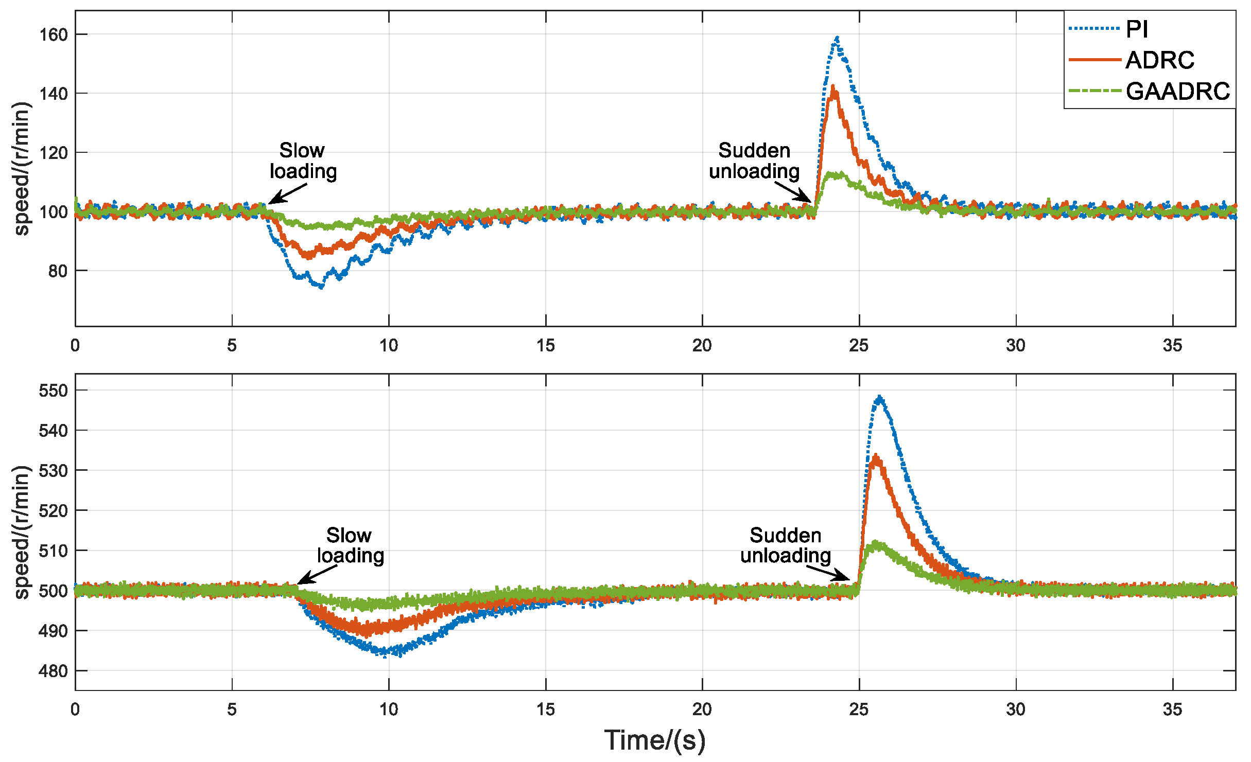
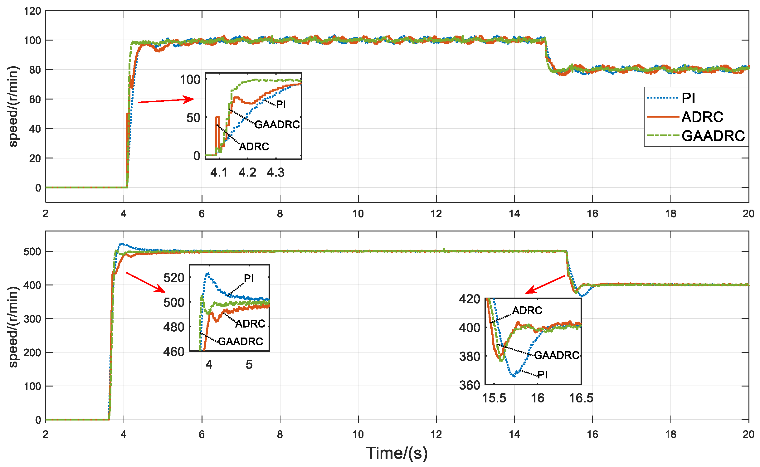
4.2. Analysis of Experimental Results

The experimental platform for a five-phase motor is shown in Figure 12. The rated voltage of the motor is 220 V, the rated frequency is 50 Hz, the rated torque is 18.23 N, and the rated speed is 2880 r/min. The powder brake is used for loading, and its maximum loading torque is 100 N·m. A torque and speed sensor is added between the motor and the powder brake, which is connected to the acquisition instrument and can directly display real-time torque and speed on the digital display screen.
PI controller, ADRC, and GAADRC parameters were used for experiments to verify the speed regulation performance of the motor under no-load acceleration and deceleration, and acceleration and deceleration under load and load reduction.
The motor was set to start up at 100 r/min and 500 r/min in no-load mode, and after a period of time the speed was reduced to 80 r/min and 400 r/min, respectively. The speed waveform of the PI controller, ADRC, and GAADRC was obtained, as shown in Figure 13. As can be seen from the figure, under no-load condition, at the given speed of 100 r/min, the PI controller, ADRC, and GAADRC speed waveforms do not overshoot, and the GAADRC reaches the given speed the fastest, followed by the ADRC. When decelerating to 80 r/min, there is little difference in speed change among the three modes. When the motor decelerates from 500 r/min to 400 r/min at the given speed, the adjustment time and overshoot in the process of motor speed regulation are shown in Table 4. As can be seen from the data in the table, compared with the PI controller, the ADRC can start without overshoot, but the adjustment time is slightly slower than that of the PI controller due to small oscillations in the startup process. The GAADRC overcomes the problem of the slow adjustment time of the ADRC and reduces the adjustment time by 77.27% in the startup process; however, it produced an overshoot of 1%. In the deceleration process, both the ADRC and GAADRC have overshoot to some extent, but their dynamic performance is better than the PI controller.
In the case of 100 r/min and 500 r/min with load, the motor speed is set to 80 r/min and 400 r/min, respectively, and then back to 100 r/min and 500 r/min, and the motor speed waveform is obtained, as shown in Figure 14. As can be seen from the figure, at the low speed of 100 r/min, both the PI controller and ADRC have a large degree of fluctuation, and there is a certain overshoot in the speed regulation process, and the overshoot of the ADRC is slightly larger than that of PI controller. Compared with the ADRC, the GAADRC has a certain degree of reduction in overshoot and speed fluctuation, and its effect is better than that of the PI controller. The adjustment time and overshoot at the initial speed of 500 r/min with load are shown in Table 5. It can be seen from the data in the table that the dynamic performance of the ADRC is better than that of the PI controller in the medium speed with load speed regulation. Based on the ADRC, the overshoot is smaller and the adjustment time is increased by about 70%.
When loading and unloading experiments are carried out, because the magnetic powder brake cannot suddenly load, the load can only be slowly added, so the speed waveform of sudden load cannot be obtained. The motor was slowly loaded and suddenly unloaded at 100 r/min and 500 r/min under a steady state, respectively. The speed waveforms of the PI controller, ADRC, and GAADRC are shown in Figure 15. The speed decreases during loading and the speed increases during unloading are shown in Table 6. It can be seen from the data in the table that, compared with the PI controller, the ADRC has a better inhibition effect on the motor loading and unloading and other external disturbances, and its performance is improved by about 30%. After using a neural network to optimize the parameters of the GAADRC, the suppression effect is more obvious compared with the ADRC, and its disturbance rejection performance improved by 60~70%.
According to the comparison of motor speed regulation performance in no-load acceleration and deceleration, and acceleration and deceleration with load and load reduction, it can be seen that the GAADRC optimized based on neural networks has a better optimization effect than the ADRC obtained through experience adjustment during motor startup and load and load reduction, and the dynamic performance of small speed regulation is not much different from that of the ADRC.

5. Conclusions

This paper mainly focused on the problem of tuning the parameters of the ADRC, proposed a unique genetic algorithm, and constructed a multi-objective optimization cost function based on a genetic algorithm to achieve the parameter tuning of the five-phase motor ADRC. After repeated iterations of the current loop and speed loop, the control parameters of the ADRC were obtained.
The simulation and experimental results indicate that the GAADRC has lower startup overshoot, faster adjustment time, and lower load/unload speed changes compared to the ADRC. Furthermore, the GAADRC can obtain all the parameters to be tuned without knowing the required parameters of the controller, reducing the time cost required for ADRC parameter tuning and helping people quickly obtain control parameters that meet the conditions for analysis and verification, which has strong practical value.

Author Contributions

Writing—original draft preparation, R.Z.; validation, Y.X.; investigation, X.L.; supervision, J.Z.; data curation, R.Z. All authors have read and agreed to the published version of the manuscript.

Funding

This research received no external funding.

Institutional Review Board Statement

Not applicable.

Informed Consent Statement

Not applicable.

Data Availability Statement

Not applicable.

Conflicts of Interest

The authors declare no conflict of interest.

References

  1. Han, J. From PID to active disturbance rejection control. IEEE Trans. Ind. Electron. 2009, 56, 900–906. [Google Scholar] [CrossRef]
  2. Huang, Y.; Han, J. Analysis and design for the second order nonlinear continuous extended states observer. Chin. Sci. Bull. 2000, 45, 1938–1944. [Google Scholar] [CrossRef]
  3. Zheng, Q.; Gao, Z.; Technology. Active disturbance rejection control: Some recent experimental and industrial case studies. Control Theory Technol. 2018, 16, 301–313. [Google Scholar] [CrossRef]
  4. Wang, H.; Pan, T.; Gao, Z.; Jin, H. Active Disturbance Rejection Control for Discrete Systems. In Proceedings of the 9th IEEE Data Driven Control and Learning Systems Conference (DDCLS), Liuzhou, China, 22 November 2020; pp. 378–382. [Google Scholar]
  5. Wu, Z.; Li, D.; Xue, Y.; Sun, L.; He, T.; Zheng, S. Modified active disturbance rejection control for fluidized bed combustor. ISA Trans. 2020, 102, 135–153. [Google Scholar] [CrossRef] [PubMed]
  6. Wang, R.; Liu, X.; Huang, Y. Synchronous Generator Excitation System for a Ship Based on Active Disturbance Rejection Control. Math. Probl. Eng. 2021, 2021, 6638370. [Google Scholar] [CrossRef]
  7. Beltran-Carbajal, F.; Valderrabano-Gonzalez, A.; Favela-Contreras, A.R.; Cesar Rosas-Caro, J. Active Disturbance Rejection Control of a Magnetic Suspension System. Asian J. Control 2015, 17, 842–854. [Google Scholar] [CrossRef]
  8. Sui, S.; Zhao, T. Active disturbance rejection control for optoelectronic stabilized platform based on adaptive fuzzy sliding mode control. ISA Trans. 2022, 125, 85–98. [Google Scholar] [CrossRef] [PubMed]
  9. Yang, H.; Cheng, L.; Xia, Y.; Yuan, Y. Active Disturbance Rejection Attitude Control for a Dual Closed-Loop Quadrotor Under Gust Wind. IEEE Trans. Control Syst. Technol. 2018, 26, 1400–1405. [Google Scholar] [CrossRef]
  10. Wang, D.; Zhao, J.; Wang, C.; Zhu, X.; Zhou, Z.; Li, W.; Jia, Y.; Li, Z.; Wu, S.; Meng, J. An adaptive linear active disturbance rejection control method for HVDC transmission system. Energy Rep. 2023, 9, 3282–3289. [Google Scholar] [CrossRef]
  11. Bingül, Ö.; Yıldız, A. Fuzzy logic and proportional integral derivative based multi-objective optimization of active suspension system of a 4× 4 in-wheel motor driven electrical vehicle. J. Vib. Control 2023, 29, 1366–1386. [Google Scholar] [CrossRef]
  12. Du, C.; Yin, Z.; Zhang, Y.; Liu, J.; Sun, X.; Zhong, Y. Research on Active Disturbance Rejection Control With Parameter Autotune Mechanism for Induction Motors Based on Adaptive Particle Swarm Optimization Algorithm With Dynamic Inertia Weight. IEEE Trans. Power Electron. 2019, 34, 2841–2855. [Google Scholar] [CrossRef]
  13. Yin, Z.; Du, C.; Liu, J.; Sun, X.; Zhong, Y. Research on Autodisturbance-Rejection Control of Induction Motors Based on an Ant Colony Optimization Algorithm. IEEE Trans. Ind. Electron. 2018, 65, 3077–3094. [Google Scholar] [CrossRef]
  14. Elmouhi, N.; Essadki, A.; Elaimani, H. Improved control for DFIG based wind power system under voltage dips using ADRC optimized by genetic algorithms. Int. J. Electr. Comput. Eng. Syst. 2022, 13, 357–367. [Google Scholar] [CrossRef]
  15. Yang, Z.; Lu, C.; Sun, X.; Ji, J.; Ding, Q. Study on Active Disturbance Rejection Control of a Bearingless Induction Motor Based on an Improved Particle Swarm Optimization-Genetic Algorithm. IEEE Trans. Transp. Electrif. 2021, 7, 694–705. [Google Scholar] [CrossRef]
  16. Ali, S.; Yang, G.; Huang, C. Performance optimization of linear active disturbance rejection control approach by modified bat inspired algorithm for single area load frequency control concerning high wind power penetration. ISA Trans. 2018, 81, 163–176. [Google Scholar] [CrossRef] [PubMed]
  17. Kang, C.; Wang, S.; Ren, W.; Lu, Y.; Wang, B. Optimization design and application of active disturbance rejection controller based on intelligent algorithm. IEEE Access 2019, 7, 59862–59870. [Google Scholar] [CrossRef]
  18. Villarreal-López, E.; Coral-Enriquez, H.; Medina-Camacho, S.; Hurtado-Cortés, L. Online parameter adjustment of an active disturbance rejection controller for a robotic manipulator via simulated annealing. In Presented at AETA 2019-Recent Advances in Electrical Engineering and Related Sciences: Theory and Application; Springer: Berlin/Heidelberg, Germany, 2021; pp. 460–469. [Google Scholar]
  19. Zeng, W.-F.; Yan, L. The parameter setting and application study of adrc based on immune genetic algorithm. In Proceedings of the 2010 IEEE International Conference on Intelligent Computing and Intelligent Systems, Xiamen, China, 29–31 October 2010; IEEE: New York, NY, USA; Volume 2, pp. 183–186. [Google Scholar]
  20. Gao, L.; Guo, X.; Mei, D.; Qu, Z. Parameter tuning of active disturbance rejection control based on improved differential evolution algorithm. In Proceedings of the 2022 7th International Conference on Intelligent Computing and Signal Processing (ICSP), Xi’an, China, 15–17 April 2022; pp. 342–346. [Google Scholar]
  21. Yildiz, A. Parametric synthesis of two different trunk lid mechanisms for sedan vehicles using population-based optimisation algorithms. Mech. Mach. Theory 2021, 156, 104130. [Google Scholar] [CrossRef]
  22. Liu, K.; Ji, H.; Zhang, Y. Extended state observer based adaptive sliding mode tracking control of wheeled mobile robot with input saturation and uncertainties. Proc. Inst. Mech. Eng. 2019, 233, 5460–5476. [Google Scholar] [CrossRef]
  23. Shin, E.-C.; Park, T.-S.; Oh, W.-H.; Yoo, J.-Y. A design method of PI controller for an induction motor with parameter variation. In Proceedings of the IECON’03. 29th Annual Conference of the IEEE Industrial Electronics Society (IEEE Cat. No. 03CH37468), Roanoke, VA, USA, 2–6 November 2003; pp. 408–413. [Google Scholar]
Figure 1. Structure block diagram of ADRC system.
Processes 11 01712 g001
Figure 2. Structure block diagram of ADRC system for five-phase motor.
Processes 11 01712 g002
Figure 3. Flowchart of the genetic algorithm.
Processes 11 01712 g003
Figure 4. Composition of random string.
Processes 11 01712 g004
Figure 5. Flowchart of ADRC parameter setting based on genetic algorithm.
Processes 11 01712 g005
Figure 6. Change process of setting parameters in step 1. (a) ADRC parameter optimization curve of speed loop. (b) ADRC parameter optimization curve of current loop. (c) The curve of optimum fitness.
Processes 11 01712 g006
Figure 7. Change process of setting parameters in step 2. (a) ADRC parameter optimization curve of current loop. (b) The curve of optimum fitness.
Processes 11 01712 g007
Figure 8. Change process of setting parameters in step 3. (a) ADRC parameter optimization curve of speed loop. (b) The curve of optimum fitness.
Processes 11 01712 g008
Figure 9. Comparison of speed waveform under no-load start and speed regulation.
Processes 11 01712 g009
Figure 10. Comparison of speed waveform under speed regulation with load.
Processes 11 01712 g010
Figure 11. Comparison of speed waveform during sudden increase and decrease in load.
Processes 11 01712 g011
Figure 12. Experimental platform of five-phase motor.
Processes 11 01712 g012
Figure 13. Motor speed waveform under no-load starting and decelerating conditions.
Processes 11 01712 g013
Figure 14. Motor speed waveform under speed regulation with load.
Processes 11 01712 g014
Figure 15. Motor speed waveform at slow loading and sudden unloading.
Processes 11 01712 g015
Table 1. Parameters of five-phase motor.
ParametersValueParametersValue
R s 1.60   Ω R r 1.35   Ω
L m d 0.7802 H L s d 0.7871 H
L r d 0.7871 HJ0.01986 kg·m2
n p 1
Table 2. Parameters of the optimized ADRC.
Parameters β 1 β 2 β 11 b 0
Speed loop4995.61440,860.8492.72259.12
Current loop9921.81999,022.5994.1435.29
Table 3. Comparison of speed overshoot during no-load startup and deceleration.
Control Mode0–100–80 r/min0–500–400 r/min0–1000–800 r/min
StartingDecelerationStartingDecelerationStartingDeceleration
PI22.82%6.75%5.16%4.17%2.75%3.99%
ADRC5.54%0.102%0.88%0.0118%0.38%0.0029%
GAADRC4.90%0.032%0.52%0.0035%0.06%0.0011%
Table 4. Adjust time and overshoot during motor startup and deceleration.
Control ModeStartup ProcessDeceleration Process
OvershootAdjust TimeOvershootAdjust Time
PI4.74%0.603 s8.65%0.67 s
ADRC0%0.695 s5.30%0.35 s
GAADRC1%0.158 s5.95%0.35 s
Table 5. Adjust the time and overshoot in the process of motor speed regulation under load.
Control ModeDeceleration ProcessStartup Process
OvershootAdjust TimeOvershootAdjust Time
PI4.78%0.816 s3.72%0.671 s
ADRC3.65%0.645 s3.20%0.210 s
GAADRC2.25%0.192 s1.18%0.062 s
Table 6. Speed drop during motor loading and speed lift during unloading.
Steady SpeedSpeed Drops When Slow
Loading (r/min)
Speed Rises When Sudden
Unloading (r/min)
PIADRCGAADRCPIADRCGAADRC
100 r/min26.516.16.359.042.513.3
500 r/min16.911.75.249.034.012.4
Disclaimer/Publisher’s Note: The statements, opinions and data contained in all publications are solely those of the individual author(s) and contributor(s) and not of MDPI and/or the editor(s). MDPI and/or the editor(s) disclaim responsibility for any injury to people or property resulting from any ideas, methods, instructions or products referred to in the content.

