Article

Study on the Influence of the Strain-Softening of the Surrounding Rock with Buried Depth on Gas Extraction Boreholes

1
School of Energy and Mining Engineering, China University of Mining and Technology-Beijing, Beijing 100083, China
2
School of Safety Engineering, North China Institute of Science and Technology, Langfang 101601, China
*
Authors to whom correspondence should be addressed.
Processes 2023, 11(6), 1680; https://doi.org/10.3390/pr11061680
Submission received: 29 April 2023 / Revised: 25 May 2023 / Accepted: 29 May 2023 / Published: 31 May 2023
(This article belongs to the Section Energy Systems)

Abstract

:
The buried depth of coal seams in China gradually increases as shallow resources decrease. The purpose of this article is to reveal the effect of buried depth on gas extraction boreholes. Firstly, we analyzed the shortcomings of the Mohr–Coulomb (M-C) constitutive model for simulating excavation problems and introduced the strain-softening (S-S) model and its advantages. Subsequently, we constructed the gas extraction models with different buried depths based on the S-S model and combined them with the evolution equations for permeability and the equations for gas migration. Then, we studied the difference between the M-C and S-S models using numerical simulations. We found that the influence of the S-S phenomenon in the surrounding rock of boreholes is more significant as the buried depth increases—that is, the strain-softening has a significant buried depth effect. When the buried depths were 300, 500, and 700 m, the maximum ratios of permeability to the initial permeability obtained from the Mohr–Coulomb model were 1.37, 6.88, and 97.56, respectively; the maximum ratios of permeability to the initial permeability obtained from the strain-softening model were 2.06, 291.23, and 3629.66. The differences in the increase zone of permeability from the two models also increased with the increase in the buried depth. The distribution curves of gas pressure in the surrounding rock of boreholes obtained from the S-S model were below those of the M-C constitutive model at the same buried depth, and the zones with slowly increasing gas pressure with the increase in buried depth were more obvious in the S-S model compared with the M-C constitutive model. The differences in borehole effective extraction radius also increased gradually between the S-S and M-C models as the buried depth increased. Through the analysis of the research results, we found that S-S of the surrounding rock has a lesser influence on the gas extraction boreholes, and the S-S phenomenon in the surrounding rock of boreholes can be ignored when the buried depth is relatively shallow. It is increasingly necessary to consider the S-S phenomenon in the surrounding rock of boreholes with the gradual increase in the buried depth.

1. Introduction

Coal mining in China has been gradually extended deeper as a result of the depletion of shallow coal resources in recent years, and some problems have gradually emerged with the increases in mining depth [1,2,3]. On the one hand, deep mines have the characteristics of high in situ stress levels, strong mining disturbances, high development of coal fractures, and the linear-to-nonlinear transformation of mechanical properties [4,5]. On the other hand, the gas pressure and contents increase as the buried depth increases in coal seams. Many mines transform from low-gas to high-gas mines or even coal and gas outburst mines after extending deeper, resulting in an increase in gas disaster accidents in mining [6,7]. The most efficacious method to control coal mine gas disaster accidents at present is to extract the gas of coal seams [8,9]. Meanwhile, utilizing the gas extracted from the coal seam can not only increase the total energy but also contribute to protecting the environment [10,11].
Experts and scholars have conducted substantial research on gas extraction technology and theory, obtaining many reasonable achievements. Gao et al. proposed a novel method for gas extraction using water-jet technology to increase the borehole diameter and discussed the influence of borehole diameter on the permeability of coal seams using numerical simulation [12]. Zhang et al. used controllable shockwaves to increase the permeability of coal seams to enhance the effectiveness of boreholes for gas extraction [13]. Xu et al. constructed a gas seepage model and analyzed the effects of the original gas pressure, borehole diameter, and negative extraction pressure on seepage [14]. Qi et al. explored the impact of deep coal-seam boreholes’ internal collapse and the loss of negative pressure on the extraction effect [15]. Cao et al. constructed a model of low-permeability fluid–solid coupling and explored the law of spatiotemporal evolution between the gas pressure and borehole diameter of hydraulic flushing boreholes using numerical software [16]. Xie et al. proposed the segmented hydraulic flushing method to extract gas from coal seams to solve the difficult problem of extracting gas from coal mines and conducted tests in the field [17]. Zhang et al. analyzed the deformation and instability mechanisms of deep soft and fractured coal seams and studied the influences of three deformation and instability modes of extraction boreholes on gas extraction [18]. Chen et al. proposed a novel gas extraction mode of comb-shaped long-borehole hydraulic fracturing in coal seam roofs to solve the difficulty of high-efficiency gas extraction from broken and soft coal seams [19]. Ren et al. discussed the effect of the coal flushing rate on in situ stress relief for improving the permeability of coal seams and the effect of borehole extraction using numerical simulation and field tests [20]. Zhang et al. constructed a mathematical fluid–solid model and studied the mechanisms and factors of enhanced extraction from adjacent gas boreholes using static blasting technology [21]. Kang et al. studied the effect of the plastic zone generated by borehole excavation on gas extraction and deduced the radius of the plastic zone of boreholes’ surrounding rock according to the elastic–plastic theory [22]. Du et al. established a model of fluid–solid coupling in borehole extraction according to the pore–fracture dual-medium pore model and studied reasonable borehole arrangements to improve gas extraction efficiency [23].
The results of previous research show that in the excavation process, the strength parameters of the surrounding rock decrease significantly in the nonlinear zone because of the continuous propagation of microcracks in rocks, i.e., the so-called surrounding rock softening phenomenon [24,25,26]. The extraction of gas from boreholes is an emblematic excavation problem. Gas extraction includes both solids and fluids, and the redistribution of in situ stress after forming a borehole will change the permeability of the surrounding rock, which can influence the gas flow near the borehole [27]. In previous studies on gas extraction, the M-C constitutive model has often been used for the solid part, regardless of the depth of the coal seams [12,15,16,18,19,20,21,22,23], ignoring the S-S phenomenon of the surrounding rock. In the background of the above problem, we established gas extraction models using COMSOL based on the evolution equations of permeability and the equations of gas migration. Furthermore, we introduced an S-S model considering the softening of the surrounding rock based on gas extraction models. Subsequently, we studied the influence of the S-S phenomenon in the surrounding rock of boreholes on gas extraction with buried depth, and we explored the buried depth effect of the S-S phenomenon.

2. The S-S Model of the Surrounding Rock of Boreholes

The M-C constitutive model is generally used in numerical simulation calculations related to coal mining. The M-C constitutive model can adequately obtain the yield range within a certain area during simulation, but the matching effect on coal and rock properties in the post-peak stage is relatively poor. The principal reason for this is that the M-C constitutive model is an ideal elastic–plastic model. The strength parameters of coal and rock are constant in numerical simulation, e.g., the cohesion is the peak cohesion, which is quite discrepant from the stress–strain curve of coal and rock. The schematic diagram of the M-C constitutive model and the stress–strain curve of coal and rock are shown in Figure 1 (where σ is the stress, ε is the strain of coal and rock, c is the cohesion, and cp is the peak cohesion).
The S-S model was developed on the basis of the M-C constitutive model, taking into account the reduction in the strength parameters of coal and rock after the peak values. The strain-softening is more compatible with the actual situation in the field. To explore the substance of the S-S phenomenon of coal and rock, Jing et al. analyzed the strength parameters of coal and rock in the post-peak stage according to the strength test data published in 18 academic journals at home and abroad, along with master’s research [28]. The study validated that the substance of the S-S phenomenon of coal and rock is that the internal friction angle remains unchanged and the cohesion decreases significantly. The full stress–strain curve of coal and rock can be simplified as a “3-line representation”, and the corresponding cohesion of coal and rock is shown in Figure 2. The full stress–strain curve can be expressed as the elastic stage, softening stage, and residual stage. The cohesion corresponding to the elastic stage is the peak cohesion cp, and the cohesion corresponding to the residual stage is the residual cohesion cr.
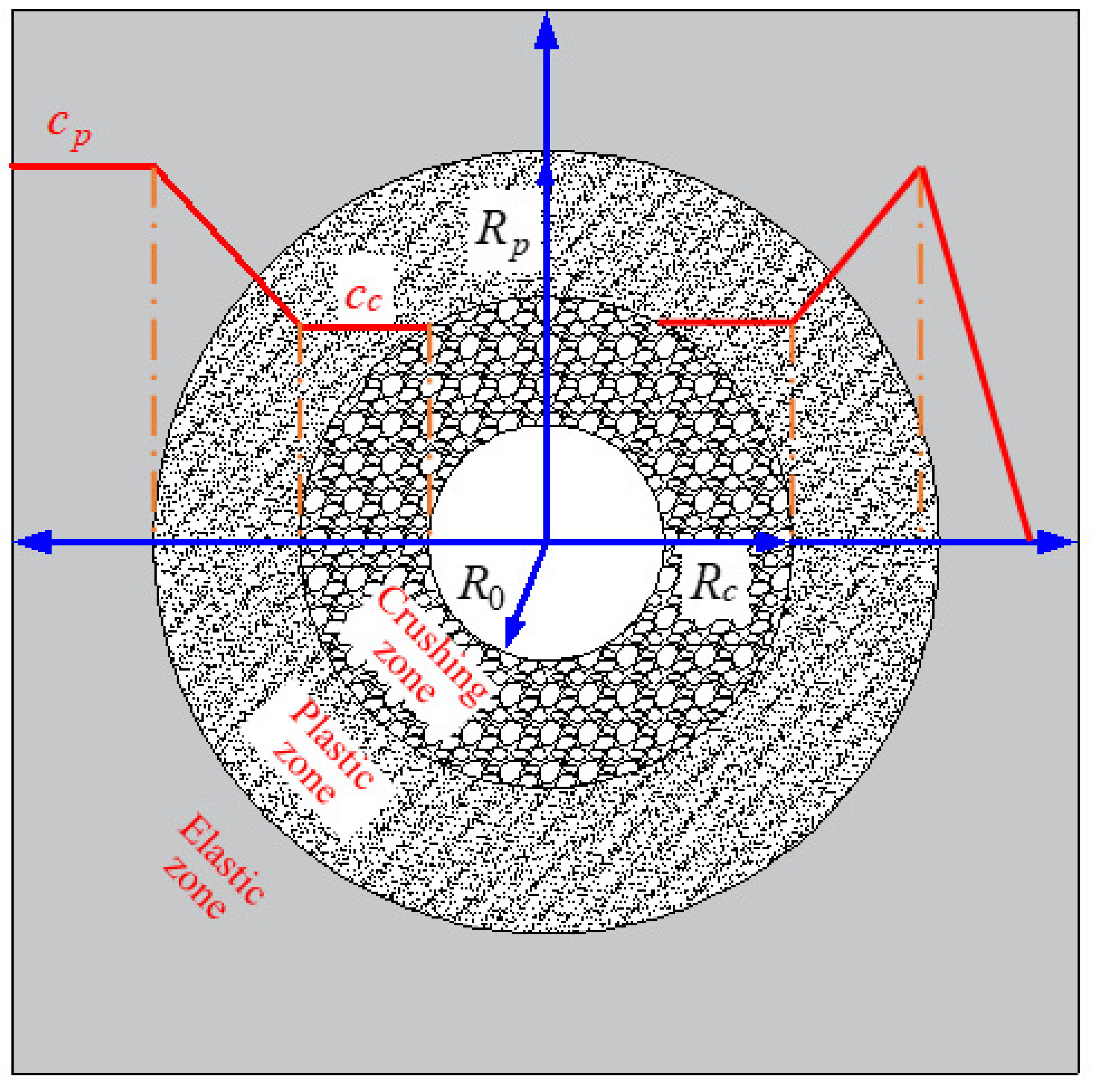
After forming boreholes, the surrounding rock of boreholes can be divided into the crushing zone, plastic zone, and elastic zone due to the redistribution of in situ stress. These three zones correspond to the residual stage, softening stage, and elastic stage in the stress–strain curve, respectively. Therefore, the cohesion in the different zones of the surrounding rock of boreholes is different, as shown in Figure 3.
Based on the results of previous research, the changes in the cohesion of coal and rock corresponding to the stress–strain curve can be formulated by the following equation [29]:
c = c p , γ p = 0 c s , 0 < γ p < γ p c r , γ p γ p
where cp is the elastic stage cohesion (MPa), cs is the plastic stage cohesion (MPa), cr is the residual stage cohesion (MPa), γp is the equivalent plastic shear strain, and γp* is the equivalent plastic shear strain at the beginning of the plastic phase (0.01).
The plastic stage cohesion can be formulated as follows:
c s = c p c p c s γ p γ p  
The equivalent plastic shear strain can be formulated by the following equation [30]:
γ p = 2 3 ε 1 p ε 1 p + ε 2 p ε 2 p + ε 3 p ε 3 p  
where ε 1 p , ε 2 p , and ε 3 p are the first, second, and third principal plastic strains, respectively.

3. Evolution Equations of Permeability and Equations of Gas Migration in the Surrounding Rock of Boreholes

3.1. Permeability Evolution Equations

The change in permeability with stress is principally caused by the change in fracture porosity. Research shows that there is a close relationship between the fracture porosity and volume strain. Regardless of the impact of gas adsorption and desorption on the fracture porosity, the fracture porosity after stress redistribution can be formulated as follows [31]:
ϕ f 1 = 1 1 + ε v ϕ f 0 + ε v  
where ϕf1 is the fracture porosity after forming boreholes, εv is the volume strain, and ϕf0 is the original fracture porosity.
The relationship between permeability and fracture porosity can be formulated as follows, according to the cubic law [32]:
k k 0 = ϕ f ϕ f 0 3  
where k is the permeability of the coal seams (m2), and k0 is the original permeability of the coal seams (m2).
Based on Equations (4) and (5), the permeability of the surrounding rock after forming boreholes can be formulated as follows:
k k 0 = 1 1 + ε v 3 1 + ε v ϕ f 0 3  

3.2. Equations of Gas Migration

Coal body is a kind of double-porous medium material, and the gas migration can be divided into two steps: First, the gas in the fractures of the rocks surrounding the borehole flows into the borehole under the action of pressure difference, and then the gas of the coal matrix block is desorbed and diffuses into the fractures as source term of fractures. The mass exchange between the gas of the coal matrix and the fractures can be formulated as follows [33]:
Q s = 1 τ M R T P m P f  
where Q s is the mass exchange rate of gas between the coal matrix and the system of fractures (kg/(m3∙s)), τ is the adsorption time (h), M is the molar mass of the gas (kg/mol), R is the gas constant (J/(mol·K)), T is the temperature of the coal seam (K), Pm is the gas pressure of the coal matrix (MPa), and Pf is the gas pressure of the fractures (MPa).
The mass exchange rate of gas between the coal matrix and the system of fractures is equal to the change in the gas content of the coal matrix system with time, according to the law of conservation of mass [34]:
Q s = m m t  
where mm is the gas content in the coal matrix (kg/m3) and t is the time (s).
The gas content in the coal matrix can be formulated as follows [35]:
m m = V L P m P m + P L M V M ρ c + ϕ m M R T P m  
where VL is the maximum gas adsorption capacity per unit volume of coal (kg/m3), VM is the molar volume of gas (L/mol), ρc is the density of the coal matrix block (kg/m3), and ϕm is the porosity of the coal matrix block.
The change equation of gas pressure in the matrix with time can be calculated by using Equations (7)–(9):
P m t + V m P m P f P m + P L 2 τ V L R T P L ρ c + τ ϕ m V M P m + P L 2 = 0  
Gas seepage in coal fractures conforms to the conservation-of-mass equation and Darcy’s law, which can be formulated using the following equations [36]:
ϕ f ρ f t + ρ f ν = Q s 1 ϕ f  
ν = k μ P f  
where ρf is the fractures’ gas density (kg/m3), ν is the seepage velocity of the gas (m/s), and μ is the viscosity of the gas (Pa∙s).
Equations (10)–(12) are the gas migration control equations.

4. The Influence of the S-S Phenomenon of the Surrounding Rock on Extraction Boreholes with Buried Depth

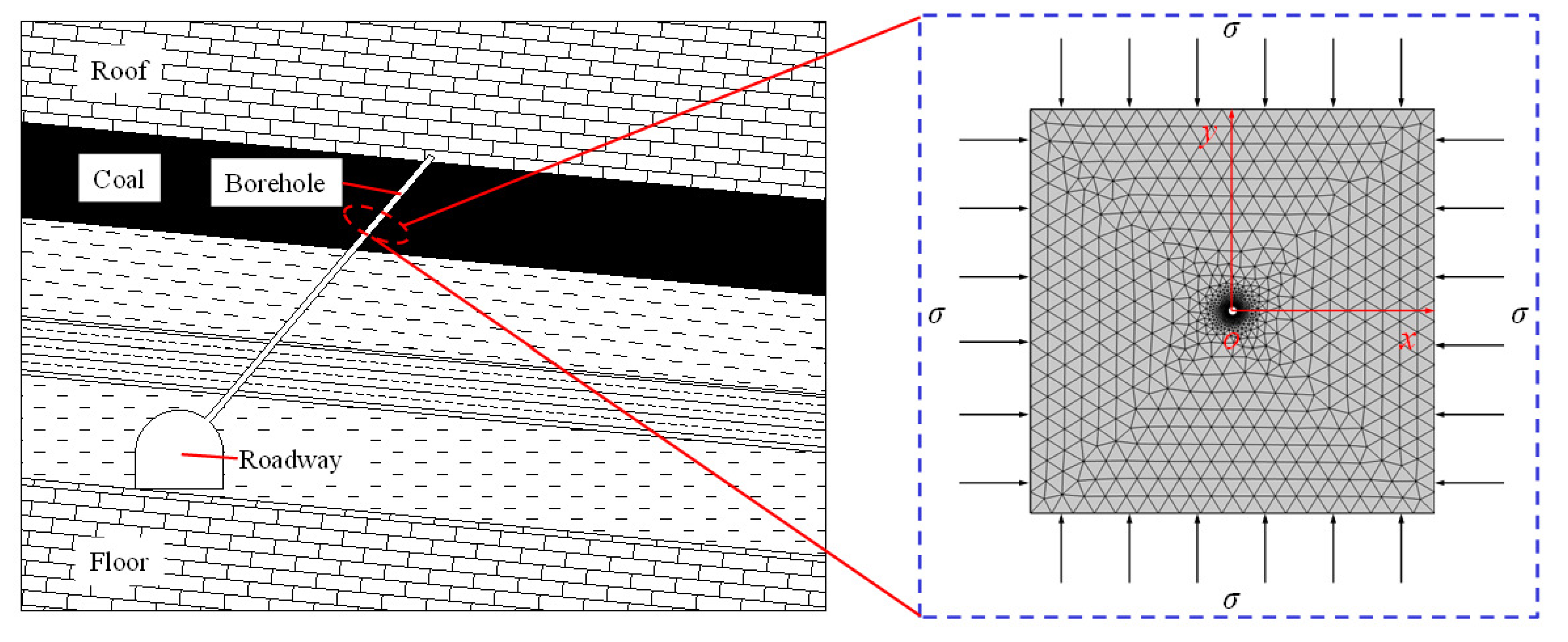
To investigate the buried depth effect of the S-S phenomenon on the surrounding rock of boreholes, we established numerical models of gas extraction using COMSOL. Assuming that the surrounding rock of boreholes is in a two-way isobaric state, since the extraction borehole’s length is much longer than its diameter, the model can be simplified as a two-dimensional plane-strain model. The model size is 10 m × 10 m, and the borehole diameter is 115 mm. The model is shown in Figure 4. The boundaries around the model are under stress and no-flow boundary conditions, and the boundaries around the borehole are under free boundary conditions. The simulation calculation process was as follows: Firstly, we selected the M-C constitutive model and combined it with the evolution equations of permeability and the equations of gas migration to analyze the distribution of stress, permeability, and gas pressure in the rock surrounding the boreholes at different buried depths. Subsequently, the M-C constitutive model was replaced by the S-S model to study the variations of stress, permeability, and gas pressure with buried depth in the rock surrounding the boreholes. The simulated buried depths were 300, 500, and 700 m. The parameters used in the numerical calculation model are shown in Table 1. These parameters mainly refer to published papers, with some modifications [37,38].

4.1. Influence of the S-S Phenomenon of the Surrounding Rock of Boreholes on the Stress Distribution with Buried Depth

The numerical calculation results of the tangential stress cloud charts in the surrounding rock of boreholes with different buried depths, calculated from the M-C constitutive model and the S-S model, are shown in Figure 5 and Figure 6, respectively.
Figure 5 and Figure 6 show that the increased portions of tangential stress in the surrounding rock of boreholes gradually move deeper with the increase in buried depth under the same model conditions. The increased portions of tangential stress in the surrounding rock of boreholes obtained from the S-S model were farther from the borehole’s boundary compared with the M-C constitutive model at the same buried depth. Meanwhile, we found that the tangential stress at the borehole boundary obtained from the S-S model was smaller than that from the M-C constitutive model at the same buried depth. Our analyses show that the width of the crushing zone of the surrounding rock of boreholes increases with the increase in the buried depth, leading to the transfer of stress to greater depths. At the same buried depth, due to the S-S phenomenon of the surrounding rock near the borehole after breakage, the bearing capacity of the surrounding rock of the boreholes decreases, leading to a decrease in the tangential stress of the surrounding rock near the borehole’s boundary and the transfer of the increased portion of tangential stress to greater depths. To more clearly observe the distribution of tangential stress of the surrounding rock of boreholes, the distribution curves of tangential stress from the borehole boundary to the model boundary were extracted and drawn into curves, as shown in Figure 7.
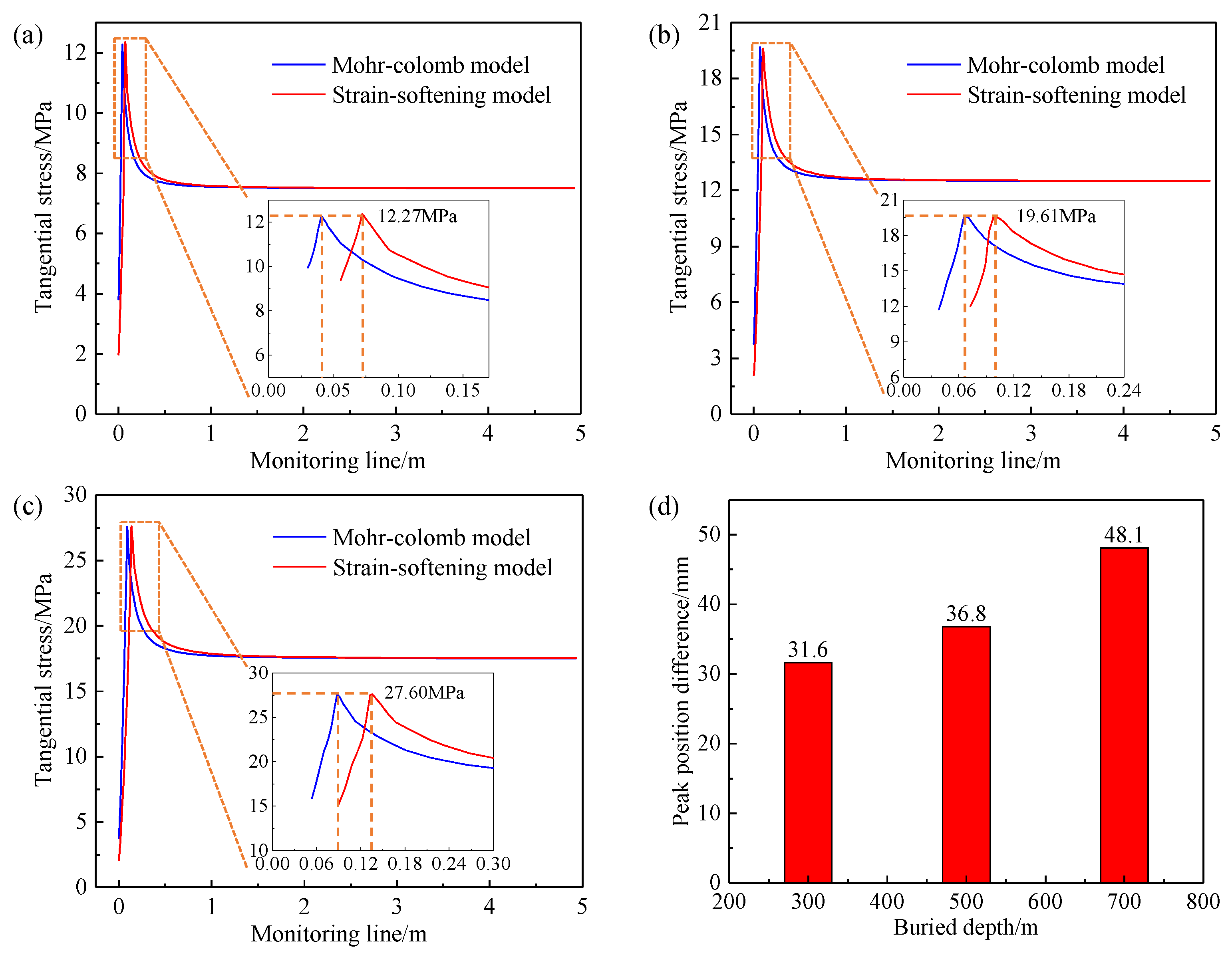
Figure 7a–c show that the tangential stress in the surrounding rock of boreholes is the lowest at the borehole boundary. The tangential stress increases to the maximum stress and then gradually reduces to the original stress along the coal body’s depth. At the same buried depth, the peak stress values obtained from the two models were the same—12.27, 19.61, and 27.60 MPa, respectively—but the peak positions obtained from the S-S model were larger than those obtained from the M-C constitutive model. Figure 7d shows the differences in the peak position between the S-S model and the M-C constitutive model. From the figure, we can see that the differences in the peak position obtained from the two models are 31.6, 36.8, and 48.1 mm at the buried depths of 300, 500, and 700 m, respectively. The differences in the peak position are larger with the increase in the buried depth. The results indicate that the S-S phenomenon of the surrounding rock has a greater effect on the tangential stress distribution around the borehole with the increase in the buried depth.

4.2. Influence of the S-S Phenomenon of the Surrounding Rock of Boreholes on the Permeability Distribution with Buried Depth

The coal seam’s permeability is a significant index to evaluate the gas extraction difficulty, and also an important parameter when studying extraction boreholes. The desorption of gas in coal seams is a slow process. The gas pressure and desorption amount change slightly at the initial formation stage of the rock surrounding the boreholes, so the change influence of gas pressure and desorption on the permeability of the surrounding rock of boreholes can be ignored, and only the influence of the redistribution of in situ stress on the permeability of surrounding rock of boreholes must be considered. The distribution cloud charts of the ratios of the permeability of the surrounding rock to the original permeability in the borehole with different buried depths, calculated by the M-C constitutive model and the S-S model, are shown in Figure 8 and Figure 9, respectively.
Figure 8 and Figure 9 show that the permeability of the surrounding rock envelope of boreholes under a two-way isobaric state is distributed in a circular shape. The ratio of permeability at the borehole’s boundary is the maximum, and the ratio of permeability from the borehole’s boundary to the bottom of the coal body gradually decreases—that is, the permeability is the greatest at the borehole’s boundary, and it gradually decreases from the borehole’s boundary to the bottom of the coal body. Under the same model, the permeability at the borehole boundary increases with the increase in the buried depth. At the same buried depth, the permeability obtained from the S-S model was larger than that obtained from the M-C constitutive model. When the buried depths were 300, 500, and 700 m, the ratios of permeability at the borehole’s boundary obtained from the M-C constitutive model were about 1.40, 7.00, and 100.00, respectively, while the ratios of permeability at the borehole’s boundary obtained from the S-S model were about 2.10, 300.00, and 3700.00, respectively.
The increase in the zone of permeability of the surrounding rock of boreholes is an indicator to evaluate the effect of boreholes’ permeability enhancement. The increase in permeability means that the ratio of the permeability of the surrounding rock to the original permeability is greater than 1. The increases in the zones of permeability of the surrounding rock of boreholes under different models are shown in Figure 10 and Figure 11.
Figure 10 and Figure 11 show that the zone of permeability gradually increases with the increase in the buried depth under the same model. The increase in the zone of permeability obtained from the S-S model was greater than that obtained from the M-C constitutive model at the same buried depth. To compare and analyze the distribution of the ratio of permeability and the variation in the increase in the zone of permeability with the buried depth for the different models more clearly, the distribution curves of the ratio of permeability and the increase in the zone of permeability for the M-C constitutive model and the S-S model at different buried depths were drawn into the same graphs, as shown in Figure 12.
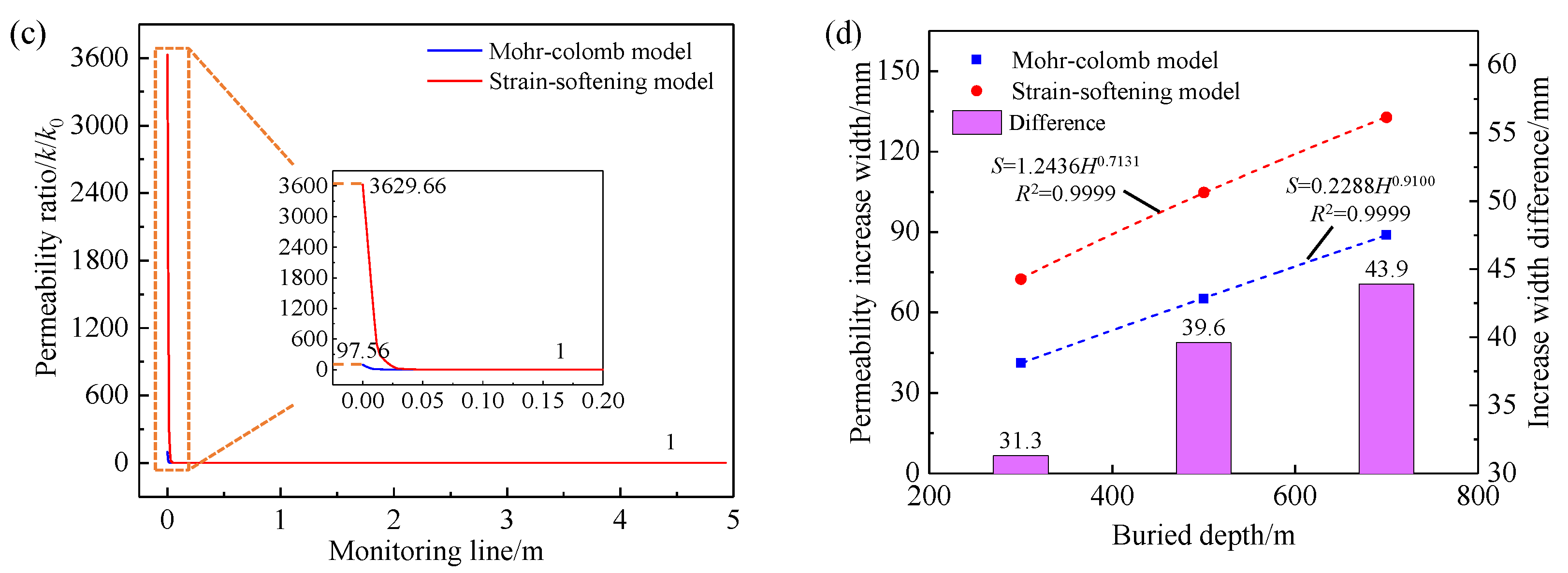
Figure 12a–c show the comparison curves of the ratio of permeability of the surrounding rock of boreholes obtained from the M-C constitutive model and the S-S model at the buried depths of 300, 500, and 700 m, respectively. From the figures, we can see that the ratio of permeability gradually decreases to 1 from the borehole boundary to the bottom of the coal body—that is, the permeability gradually decreases to the original permeability. When the buried depth is 300 m, the permeability ratios at the borehole boundary of the M-C constitutive model and the S-S model are 1.37 and 2.06, respectively. When the buried depth is 500 m, the ratios of permeability at the borehole boundary of the M-C constitutive model and the S-S model are 6.88 and 291.23, respectively. When the buried depth is 700 m, the ratios of permeability at the borehole boundary of the M-C constitutive model and the S-S model are 97.56 and 3629.66, respectively. From the comparative analysis, we found that the ratio of permeability increased significantly with the increase in the buried depth under both models, indicating that the buried depth has a significant influence on the permeability of the surrounding rock of boreholes. At the same buried depth, the ratios of permeability obtained from the S-S model were larger than those obtained from the M-C constitutive model, and the S-S model showed a greater increase in the ratios of permeability with the increase in the buried depth compared to the M-C constitutive model. This indicates that the deeper the buried depth, the more prominent the influence of strain-softening on the surrounding rock of boreholes.
Figure 12d shows the variation curves of the increase in the zone of permeability with buried depth. From the figure, we can see that the increase in the width of the zone of permeability S (the width from the borehole’s boundary to the permeability ratio of exactly 1) is positively correlated with the buried depth H under the two models, which is consistent with the power function relationship. The increase in the width of the zone of permeability obtained from the M-C model was consistent with the buried depth: S = 0.2288H0.9100. The increase in the width of the zone of permeability obtained from the S-S model was also consistent with the buried depth: S = 1.2436H0.7131. Meanwhile, we can also see from the figure that the differences in the increase in the width of the zone of permeability obtained from the S-S model and the M-C constitutive model increase with the increase in the burial depth. The differences in the increase in the width of the zone of permeability obtained from the S-S model and the M-C constitutive model were 31.3, 39.6, and 43.9 mm for the buried depths of 300, 500, and 700 m, respectively.

4.3. Influence of the S-S Phenomenon of the Surrounding Rock of Boreholes on the Distribution of Gas Pressure with Buried Depth

Coal seams’ gas pressure is one of the important parameters of gas occurring in coal mines, and it is also one of the important indicators to evaluate whether the coal seam gas poses a potential hazard. Therefore, coal mines usually use the residual pressure of gas to evaluate the effectiveness of borehole extraction. The cloud charts of the distribution of gas pressure in the surrounding rock of boreholes with different buried depths for 30 days of extraction, obtained from the M-C constitutive model and the S-S model, are shown in Figure 13 and Figure 14, respectively.
Figure 13 and Figure 14 show that the gas pressure in the surrounding rock envelope of boreholes under a two-way isobaric state is distributed in a circular shape. The gas pressure is the lowest at the borehole’s boundary, and it gradually increases to the original gas pressure from the borehole’s boundary to the bottom of the coal body. Under the same model, the zone of low gas pressure near the borehole increases with the increase in the buried depth (red zone in the figures). At the same buried depth, the zone of low gas pressure in the S-S model was larger than that in the M-C constitutive model. This indicates that the S-S phenomenon of the surrounding rock of boreholes also has an influence on the distribution law of gas pressure. In practical field applications, the effective extraction radius of the borehole is commonly used to evaluate the gas extraction effect of boreholes, and the effective extraction radius is also an important parameter to define the spacing of boreholes. The method of relative gas pressure is commonly used to determine the effective extraction radius of boreholes for coal seam gas below 0.74 MPa—that is, the gas pressure drops to 51% as the standard extraction boundary [39]. The distance from the standard extraction boundary to the borehole center is the effective extraction radius of the borehole. In this study, the standard extraction boundary for the borehole is that the gas pressure is below 0.245 MPa. The standard extraction zones of boreholes at different buried depths obtained from the M-C constitutive model and the S-S model are shown in Figure 15 and Figure 16, respectively.
From the above figures, we can observe that the standard extraction zone of boreholes increases gradually with the increase in the buried depth under the same model. At the same buried depth, the standard extraction zones of boreholes obtained from the S-S model were larger than those obtained from the M-C constitutive model. To compare and analyze the distribution of gas pressure in the surrounding rock of boreholes and the variation law of the effective extraction radius of boreholes with buried depth under different models, the distribution curves of gas pressure and the effective extraction radius curves of the M-C constitutive model and the S-S model at different buried depths were drawn into the same graphs, as shown in Figure 17.
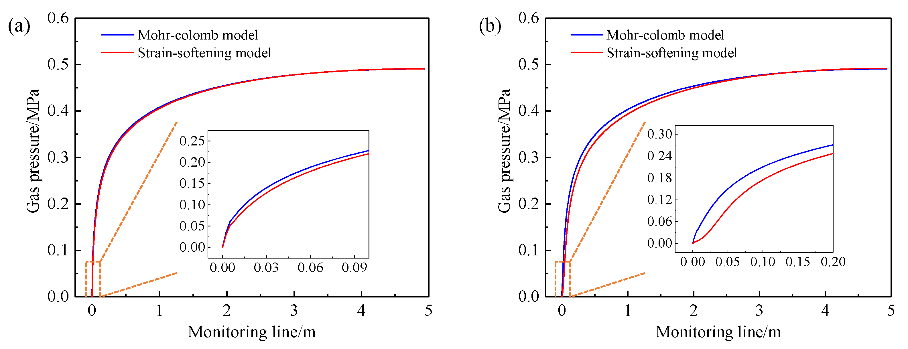
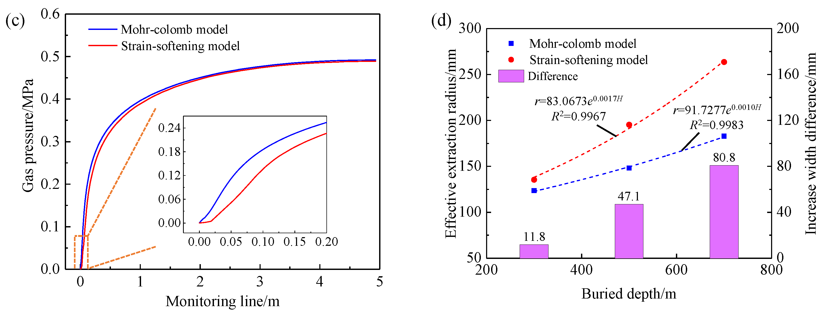
Figure 17a–c show the comparison curves of gas pressure in the surrounding rock of boreholes for the M-C constitutive model and the S-S model at buried depths of 300, 500, and 700 m, respectively. From the figures, we can recognize that the curves of gas pressure obtained from the S-S model are below those obtained from the M-C constitutive model at the same buried depths, indicating that the gas pressure obtained from the S-S model is lower than that obtained from the M-C constitutive model at the same position from the borehole boundary. The difference between the curves obtained from the two models is greater in a certain range with the increase in the buried depth, indicating that the influence of the S-S phenomenon on the distribution of gas pressure increases gradually with the increase in the buried depth. We can also see that a slowly increasing zone of gas pressure will appear near the borehole’s boundary with the increase in the buried depth, in which the value of gas pressure and its rate of increase are relatively low. The slowly increasing zone of gas pressure under the S-S model is more obvious than that under the M-C constitutive model. From the above analysis, we hypothesize that the reason for the results is that the permeability of the surrounding rock near the borehole’s boundary significantly increases with the increase in the buried depth, which leads to easier communication between this part and the outside, and the gas can flow into the boreholes more easily. At the same buried depth, the permeability and its amplitude obtained from the S-S model are larger than those obtained from the M-C constitutive model with the increase in the buried depth, which is reflected in the effect on the gas pressure distribution, as the slowly increasing zone of gas pressure under the S-S model is larger than that under the M-C constitutive model.
Figure 17d shows the variation curves of the effective extraction radius of gas boreholes with the buried depth. From the figure, we can observe that the effective extraction radius r of boreholes is positively correlated with the buried depth H under the two models, which is consistent with the exponential function relationship. The effective extraction radius of gas boreholes obtained from the M-C constitutive model is consistent with the buried depth: r = 91.7277e0.0010H. The effective extraction radius of gas boreholes obtained from the S-S model is also consistent with the buried depth: r = 83.0673e0.0017H. We can also see from the figure that the differences in the effective extraction radius of gas boreholes obtained from the S-S model and the M-C constitutive model increase with the increase in the buried depth. When the buried depths are 300, 500, and 700 m, the effective extraction radius of gas boreholes from the S-S model is 135.4, 195.3, and 263.6 mm, respectively, and the effective extraction radius of gas boreholes from the M-C constitutive model is 123.6, 148.2, and 182.8 mm, respectively. The differences in the effective extraction radius obtained from the S-S model and the M-C at these depths are 11.8, 47.1, and 80.8 mm, respectively.
According to the study of the distribution of stress, permeability, and gas pressure in the surrounding rock of boreholes at different buried depths, we can recognize that the S-S phenomenon of the surrounding rock has an effect on the stress, permeability, and gas pressure of the surrounding rock of the boreholes. The S-S phenomenon of the surrounding rock of boreholes has a significant effect on the buried depth. The greater the buried depth, the more significant the effect of the S-S phenomenon. When the buried depth is shallow, the differences in the permeability, gas pressure, and effective extraction radius of the surrounding rock of boreholes obtained from the M-C constitutive model and the S-S model are not large, so ignoring the influence of the S-S phenomenon of the surrounding rock of boreholes produces little error in the research results. When the buried depth is deep, the permeability, gas pressure, and effective extraction radius obtained from the M-C constitutive model and the S-S model differ greatly, and ignoring the effect of the S-S phenomenon in the surrounding rock of the boreholes will have a significant effect on the research results. Therefore, the influence of the S-S phenomenon of the surrounding rock of boreholes cannot be ignored when studying gas extraction in deep coal seams.

5. Discussion

China’s shallow coal resources will be mined out after long-term large-scale mining—especially the main coal consumption areas in the central and eastern regions of the North-China-type coalfield. The coal seam depth of the principal mines has reached as deep as 800~1000 m, and there are more than 50 mines with a mining depth of over 1000 m, while the maximum coal seam depth has reached 1501 m [40,41]. More and more mines will transition to deep mining in the future. Usually, the coal body has a low strength and is unable to resist the high stress caused by the redistribution of stress after forming boreholes, resulting in damage to the surrounding rock near boreholes. Additionally, the damaged coal body has a reduced strength due to the S-S phenomenon, which has an impact on the distribution of the stress, permeability, and gas pressure. From the above results, we can recognize that the permeability, the increase in the width of the zone of permeability, the distribution of gas pressure, and the effective extraction radius of gas boreholes obtained from the S-S model will all differ compared with the M-C constitutive model. Moreover, the error of the results obtained from two models increases gradually with the increase in the buried depth. Therefore, the S-S phenomenon of the surrounding rock of boreholes should be considered when studying the gas extraction of deep coal mines. Meanwhile, with the development of technology in recent years, some new technologies for gas extraction in coal mines —such as hydraulic flushing and mechanical reaming—have emerged. These technologies use a high-pressure water jet or metal mechanical arms to break the coal body and then use water flow to flush out the coal, expanding the original borehole diameter to achieve the purpose of increasing the gas extraction efficiency. The hydraulic flushing and mechanical reaming technologies cause greater disturbance and damage to the coal body compared with the original borehole. Consideration of the S-S phenomenon of the surrounding rock of boreholes is even more necessary when studying the use of these technologies in deep coal mines.

6. Conclusions

(1)
We established the models of gas extraction at different buried depths according to the S-S model, which is more realistic in the field, and combined it with the evolution equations of permeability and the equations of gas migration based on the analysis of the shortcomings of the M-C constitutive model for simulating the excavation problems. Then, the results were compared with the M-C constitutive model.
(2)
The permeability of the surrounding rock of boreholes is sensitive to the buried depth and the strain-softening. The maximum permeability ratios obtained from the M-C constitutive model and the S-S model were 1.37 and 2.06, 6.88 and 291.23, and 97.56 and 3629.66 for buried depths of 300, 500, and 700 m, respectively. When the buried depths were 300, 500, and 700 m, the increases in the width of the zone of permeability obtained from the strain-softening model at the above depths were 31.3, 39.6, and 43.9 mm larger than those obtained from the Mohr–Coulomb constitutive model, respectively.
(3)
The influence of the S-S phenomenon of the surrounding rock on the distribution of the gas pressure and the effective extraction radius of gas boreholes increases with the increase in the buried depth. At the same buried depth, the gas pressure curves obtained from the S-S model were below those obtained from M-C constitutive model. A slowly increasing zone of gas pressure will appear near the borehole’s boundary with the increase in the buried depth, and the slowly increasing zone of gas pressure obtained from the S-S model is more obvious than that obtained from the M-C constitutive model. The differences in the effective extraction radius of gas boreholes obtained from the S-S model and the M-C constitutive model also increase gradually with the increase in the buried depth: which are 11.8, 47.1, and 80.8 mm for buried depths of 300, 500, and 700 m, respectively.
(4)
The results of this research show that the influence of the S-S phenomenon of the surrounding rock of boreholes is more significant with the increase in the buried depth; that is, the strain-softening has an obvious buried depth effect. When the buried depth is shallow (no more than 300 m under the coal seam parameters in this paper), the permeability, gas pressure, and effective extraction radius of the borehole obtained from the M-C constitutive model and the S-S model are not significantly different, and the S-S phenomenon of the surrounding rock of the borehole can be ignored. It is increasingly necessary to consider the S-S phenomenon of the surrounding rock of boreholes with the increase in the buried depth when studying gas extraction boreholes.

Author Contributions

Conceptualization, J.C. and Y.H.; methodology, Y.Z. and S.X.; software, J.C. and X.Y.; investigation, D.C. and Y.R.; writing—original draft preparation, J.C. and Y.H.; writing—review and editing, Y.Z. and X.Y. All authors have read and agreed to the published version of the manuscript.

Funding

This research was funded by the National Natural Science Foundation of China (Grant No. 52074296, 52004286), the China Postdoctoral Science Foundation (Grant No. 2020T130701, 2019M650895), the State Key R&D Plan (2017YFC0804303) of the Ministry of Science and Technology of China, and the Fundamental Research Funds for the Central Universities (3142019010).

Data Availability Statement

The data are available from the corresponding author upon reasonable request.

Acknowledgments

We would also like to thank the anonymous reviewers for their valuable comments and suggestions, which led to substantial improvements of the manuscript.

Conflicts of Interest

The authors declare no conflict of interest.

References

  1. Wang, L.; Liu, S.; Cheng, Y.; Yin, G.; Zhang, D.; Guo, P. Reservoir reconstruction technologies for coalbed methane recovery in deep and multiple seams. Int. J. Min. Sci. Technol. 2017, 27, 277–284. [Google Scholar] [CrossRef]
  2. Xie, H.; Ju, Y.; Ren, S.; Gao, F.; Liu, J.; Zhu, Y. Theoretical and technological exploration of deep in situ fluidized coal mining. Front. Energy 2019, 13, 603–611. [Google Scholar] [CrossRef]
  3. Kang, H.; Jiang, P.; Huang, B.; Guan, X.; Wang, Z.; Wu, Y.; Gao, F.; Yang, J.; Cheng, L.; Zheng, Y.; et al. Roadway strata control technology by means of bolting-modification-destressing in synergy in 1000m deep coal mines. J. China Coal Soc. 2020, 45, 845–864. [Google Scholar]
  4. Jing, H.; Meng, Q.; Zhu, J.; Meng, B.; Yu, L. Theoretical and technical progress of stability control of broken rock zone of deep roadway surrounding rock. J. Min. Saf. Eng. 2020, 37, 429–442. [Google Scholar]
  5. Cheng, L.; Kang, H.; Jiang, P.; Li, W.; Yang, J.; Zheng, Y.; Yi, K. Deformation and failure characteristics and control technology of surrounding rocks in deeply gob-side entry driving. J. Min. Saf. Eng. 2021, 38, 227–236. [Google Scholar]
  6. Sun, H.; Dai, L.; Lu, J.; Cao, J.; Li, M. Analyzing energy transfer mechanism during coal and gas protrusion in deep mines. Processes 2022, 10, 2634. [Google Scholar] [CrossRef]
  7. Yuan, L. Strategic thinking of simultaneous exploitation of coal and gas in deep mining. J. China Coal Soc. 2016, 41, 1–6. [Google Scholar]
  8. Zhou, F.; Sun, Y.; Li, H.; Yu, G. Research on the theoretical model and engineering technology of the coal seam gas drainage hole sealing. J. China Univ. Min. Technol. 2016, 45, 433–439. [Google Scholar]
  9. Xu, C.; Wang, J.; Du, C.; Zhou, A.; Wang, K. Simulation of attenuation mechanism of negative pressure along the hole length of long boreholes in gas drainage and its influencing factors. J. Min. Saf. Eng. 2021, 38, 419–428. [Google Scholar]
  10. Hook, M.; Tang, X. Depletion of fossil fuels and anthropogenic climate changed: A review. Energy Policy 2013, 52, 797–809. [Google Scholar] [CrossRef]
  11. Wang, L.; Cheng, Y. Drainage and utilization of Chinese coal mine methane with a coal methane co-exploitation model: Analysis and projections. Resour. Policy 2012, 37, 315–321. [Google Scholar] [CrossRef]
  12. Gao, Y.; Lin, B.; Yang, W.; Li, Z.; Pang, Y.; Li, H. Drilling large diameter cross-measure boreholes to improve gas drainage in highly gassy soft coal seams. J. Nat. Gas Sci. Eng. 2015, 26, 193–204. [Google Scholar] [CrossRef]
  13. Zhang, Y.; Meng, Z.; Qin, Y.; Zhang, Z.; Zhao, Y.; Qiu, A. Innovative engineering practice of soft coal seam permeability enhancement by controllable shock wave for mine gas extraction: A case of Zhongjing Mine, Shuicheng, Guizhou Province, China. J. China Coal Soc. 2019, 44, 2388–2400. [Google Scholar]
  14. Xu, H.; Wang, G.; Guo, Y.; Chang, B.; Hu, Y.; Fan, J. Theoretical, numerical, and experimental analysis of effective extraction radius of coalbed methane boreholes by a gas seepage model based on defined criteria. Energy Sci. Eng. 2020, 8, 880–897. [Google Scholar] [CrossRef]
  15. Qi, Q.; Jia, X.; Zhou, X.; Zhao, Y. Instability-negative pressure loss model of gas drainage borehole and prevention technique: A case study. PLoS ONE 2020, 15, e0242719. [Google Scholar] [CrossRef]
  16. Cao, Z.; Wang, E.; He, X.; Wang, H.; Liu, Q.; Zhang, G.; Luo, F.; Wang, C.; Xu, Y. Effect evaluation of pressure relief and gas drainage of hydraulic punching in short-distance coal seam group with the risk of outburst. J. Min. Saf. Eng. 2021, 38, 634–642. [Google Scholar]
  17. Xie, S.; Cui, J.; Chen, D.; Chen, P. Numerical simulation study on gas drainage by interval hydraulic flushing in coal seam working face. Energy Explor. Exploit. 2021, 39, 1123–1142. [Google Scholar] [CrossRef]
  18. Zhang, X.; Shen, S.; Feng, X.; Ming, Y.; Liu, J. Influence of deformation and instability of borehole on gas extraction in deep mining soft coal seam. Adv. Civ. Eng. 2021, 2021, 6689277. [Google Scholar] [CrossRef]
  19. Chen, D.; Wang, J.; Jia, B.; Xi, J. High-efficiency regional gas drainage model after hydraulic fracturing of comb-shaped long boreholes in the roof of broken soft and low permeability coal seam. Coal Geol. Explor. 2022, 50, 29–36. [Google Scholar]
  20. Ren, P.; Liu, Y.; Han, H.; Wang, D.; Zuo, W.; Li, Y.; Shi, C. Study on influence laws of coal flushing rate on coal seam stress relief and gas extraction. Coal Sci. Technol. 2022, 50, 102–109. [Google Scholar]
  21. Zhang, X.; Zhou, F.; Zou, J. Numerical simulation of gas extraction in coal seam strengthened by static blasting. Sustainability 2022, 14, 12484. [Google Scholar] [CrossRef]
  22. Kang, Y.; Geng, Z.; Liu, B.; Chen, J. Study on gas extraction efficiency using in-seam borehole method considering influence of plastic zone induced by borehole drilling. Geomech. Energy Environ. 2023, 33, 100426. [Google Scholar] [CrossRef]
  23. Du, F.; Cui, W.; Wang, K. Study on Gas migration mechanism and multi-borehole spacing optimization in coal under negative pressure extraction. Processes 2023, 11, 259. [Google Scholar] [CrossRef]
  24. Zhou, J.; Xu, W.; Li, M.; Zhou, X.; Shi, C. Application of rock strain softening model to numerical analysis of deep tunnel. Chin. J. Rock Mech. Eng. 2009, 28, 1116–1127. [Google Scholar]
  25. Leandro, A.; Alfonso, R.; Maria, V. Plastic radii and longitudinal deformation profiles of tunnels excavated in strain-softening rock masses. Tunn. Undergr. Space Technol. 2012, 30, 169–192. [Google Scholar]
  26. Cao, R.; Cao, P.; Zhang, K.; Lin, H. Stability analysis of roadway intersection considering strain softening. Rock Soil Mech. 2013, 34, 73–77. [Google Scholar]
  27. Hou, Y.; Cui, J.; Liu, R. Study on the long-distance gas pre-drainage technology in the heading face by directional long borehole. Energies 2022, 15, 6304. [Google Scholar] [CrossRef]
  28. Jing, W.; Xue, W.; Yao, Z. Variation of the internal friction angle and cohesion of the plastic softening zone rock in roadway surrounding rock. J. China Coal Soc. 2018, 43, 2203–2210. [Google Scholar]
  29. González-Cao, J.; Varas, F.; Bastante, F.; Alejano, L. Ground reaction curves for circular excavations in non-homogeneous, axisymmetric strain-softening rock masses. J. Rock Mech. Geotech. 2013, 5, 431–442. [Google Scholar] [CrossRef]
  30. Alonso, E.; Alejano, L.; Varas, F.; Fdez-Manin, G.; Carranza-Torres, C. Ground response curves for rock masses exhibiting strain-softening behaviour. Int. J. Numer. Anal. Methods Geomech. 2003, 27, 1153–1185. [Google Scholar] [CrossRef]
  31. Cui, J.; Hou, Y.; Xie, S.; Chen, D.; Yan, X.; Meng, S. Study on the effect of strain-softening on permeability and gas pressure in surrounding rocks of a hydraulic flushing borehole. ACS Omega 2002, 8, 15501–15517. [Google Scholar] [CrossRef]
  32. Zhang, L.; Zhou, H.; Wang, X.; Rong, T.; Chen, C. Characteristics of deep coalbed gas migration based on the time-dependent effect. J. China Coal Soc. 2019, 44, 1771–1779. [Google Scholar]
  33. Mora, C.; Wattenbarger, R. Analysis and verification of dual porosity and CBM shape factors. J. Can. Pet. Technol. 2009, 48, 17–21. [Google Scholar] [CrossRef]
  34. Liu, Q.; Cheng, Y.; Wang, H.; Zhou, H.; Liang, W.; Wei, L.; Liu, H. Numerical assessment of the effect of equilibration time on coal permeability evolution characteristics. Fuel 2015, 140, 81–89. [Google Scholar] [CrossRef]
  35. Yuan, X.; Liang, B.; Sun, W.; Zhang, X. Research on permeability evolution model for coal seam being drained by pressure relief. China Saf. Sci. J. 2016, 26, 127–131. [Google Scholar]
  36. Tu, Q.; Cheng, Y.; Liu, Q.; Guo, P.; Wang, L.; Li, W.; Jiang, J. Investigation of the formation mechanism of coal spallation through the cross-coupling relations of multiple physical processes. Int. J. Rock Mech. Min. Sci. 2018, 105, 133–144. [Google Scholar] [CrossRef]
  37. Kong, X.; Wang, E.; Liu, X.; Li, N.; Chen, L.; Feng, J.; Kong, B.; Li, D.; Liu, Q. Coupled analysis about multi-factors to the effective influence radius of hydraulic flushing: Application of response surface methodology. J. Nat. Gas Sci. Eng. 2016, 32, 538–548. [Google Scholar] [CrossRef]
  38. Zhang, H.; Cheng, Y.; Liu, Q.; Yuan, L.; Dong, J.; Wang, L.; Qi, Y.; Wang, W. A novel in-seam borehole hydraulic flushing gas extraction technology in the heading face: Enhanced permeability mechanism, gas flow characteristics, and application. J. Nat. Gas Sci. Eng. 2017, 46, 498–514. [Google Scholar] [CrossRef]
  39. Liu, S.; Ma, G.; Lu, J.; Lin, B. Relative pressure determination technology for effective radius found on gas content. J. China Coal Soc. 2011, 36, 1715–1719. [Google Scholar]
  40. Xie, H.; Gao, F.; Ju, Y. Research and development of rock mechanics in deep ground engineering. Chin. J. Rock Mech. Eng. 2015, 34, 2161–2178. [Google Scholar]
  41. Huang, B.; Zhang, N.; Jing, H.; Kan, J.; Meng, B.; Li, N.; Xie, W.; Jiao, J. Large deformation theory of rheology and structural instability of the surrounding rock in deep mining roadway. J. China Coal Soc. 2020, 45, 911–926. [Google Scholar]
Figure 1. The schematic diagram of the M-C constitutive model and the stress–strain curve of coal and rock: (a) M-C constitutive model; (b) stress–strain curve of coal and rock.
Processes 11 01680 g001
Figure 2. The full stress–strain curve of coal and rock, and the corresponding cohesion.
Processes 11 01680 g002
Figure 3. Stress zoning and corresponding cohesion of the surrounding rock of a borehole.
Processes 11 01680 g003
Figure 4. Model diagram.
Processes 11 01680 g004
Figure 5. The distribution cloud charts of tangential stress in the surrounding rock of the borehole at different buried depths under the M-C constitutive model: (a) buried depth of 300 m; (b) buried depth of 500 m; (c) buried depth of 700 m.
Processes 11 01680 g005
Figure 6. The distribution cloud charts of tangential stress in the surrounding rock of the borehole at different buried depths under the S-S model: (a) 300 m; (b) 500 m; (c) 700 m.
Processes 11 01680 g006
Figure 7. The distribution curves of tangential stress and peak position differences of the surrounding rock at different buried depths: (a) 300 m; (b) 500 m; (c) 700 m; (d) peak position difference.
Processes 11 01680 g007
Figure 8. The distribution cloud charts of the ratios of permeability of the surrounding rock to the original permeability at different buried depths under the M-C constitutive model: (a) 300 m; (b) 500 m; (c) 700 m.
Processes 11 01680 g008
Figure 9. The distribution cloud charts of the ratios of permeability of the surrounding rock to the original permeability at different buried depths under the S-S model: (a) 300 m; (b) 500 m; (c) 700 m.
Processes 11 01680 g009
Figure 10. The cloud charts of the increase in the zone of permeability of the surrounding rock of boreholes at different buried depths under the M-C constitutive model: (a) 300 m; (b) 500 m; (c) 700 m.
Processes 11 01680 g010
Figure 11. The cloud charts of the increase in the zone of permeability of the surrounding rock of boreholes at different buried depths under the S-S model: (a) 300 m; (b) 500 m; (c) 700 m.
Processes 11 01680 g011
Figure 12. The distribution curves of the ratio of permeability and the increase in the zone of permeability for the M-C constitutive model and the S-S model at different buried depths: (a) 300 m; (b) 500 m; (c) 700 m; (d) permeability increase range curves.
Processes 11 01680 g012aProcesses 11 01680 g012b
Figure 13. The cloud charts of the distribution of gas pressure in the surrounding rock of boreholes at different buried depths, obtained from the M-C constitutive model: (a) 300 m; (b) 500 m; (c) 700 m.
Processes 11 01680 g013
Figure 14. The cloud charts of the distribution of gas pressure in the surrounding rock of boreholes at different buried depths, obtained from the S-S model: (a) 300 m; (b) 500 m; (c) 700 m.
Processes 11 01680 g014
Figure 15. The standard extraction zones of boreholes at different buried depths under the M-C constitutive model: (a) 300 m; (b) 500 m; (c) 700 m.
Processes 11 01680 g015
Figure 16. The standard extraction zones of boreholes at different buried depths under the S-S model: (a) 300 m; (b) 500 m; (c) 700 m.
Processes 11 01680 g016
Figure 17. Distribution curves of gas pressure and effective extraction radius curves of boreholes in the M-C constitutive model and the S-S model at different buried depths: (a) 300 m; (b) 500 m; (c) 700 m; (d) effective extraction radius of gas boreholes.
Processes 11 01680 g017aProcesses 11 01680 g017b
Table 1. Parameters used in the numerical calculation model.
ParametersValueParametersValue
Elastic modulus (E/MPa)1.2Original gas pressure (P0/MPa)0.5
Internal friction angle (φ/°)30Adsorption time (τ/h)6
Poisson’s ratio (υ)0.3Molar mass of gas (M/g·mol−1)16
Density of coal matrix (ρc/kg/m3)1400Gas constant (R/J·mol−1·K−1)8.314
Peak cohesion (cp/MPa)1.1Temperature of coal seam (T/K)293
Residual cohesion (cr/MPa)0.6Maximum gas adsorption per unit volume of coal (VL/kg·m−3)24
Original fracture porosity (ϕf0)0.04Molar volume of gas (VM/L·mol−1)22.4
Original permeability (k0/m2)1.8 × 10−12Coal matrix porosity (ϕm)0.06
Langmuir pressure constant (PL/MPa)1.0Viscosity of gas (μ/Pa·s)1.84 × 10−5
Disclaimer/Publisher’s Note: The statements, opinions and data contained in all publications are solely those of the individual author(s) and contributor(s) and not of MDPI and/or the editor(s). MDPI and/or the editor(s) disclaim responsibility for any injury to people or property resulting from any ideas, methods, instructions or products referred to in the content.