Article

Prediction of Favourable Hydrocarbon Transport Pathways of the Jiuzhou Fault in Langgu Sag, Bohai Bay Basin

1
School of Earth Sciences, Northeast Petroleum University, Daqing 163318, China
2
Key Laboratory of Natural Gas Sealing Mechanism, CNPC Key Laboratory of Gas Reservoir Formation and Development, Daqing 163318, China
3
Great Wall Drilling Company, CNPC, Panjin 124000, China
*
Author to whom correspondence should be addressed.
Processes 2023, 11(6), 1666; https://doi.org/10.3390/pr11061666
Submission received: 14 April 2023 / Revised: 24 May 2023 / Accepted: 26 May 2023 / Published: 30 May 2023
(This article belongs to the Section Energy Systems)

Abstract

:
The Jiuzhou fault in the Langgu Sag of the Bohai Bay Basin is a significant oil-source fault that connects source rocks and reservoirs, and thus it can transport oil and gas during the hydrocarbon accumulation period. The hydrocarbon distribution characteristics along the strike of the Jiuzhou fault differ distinctly, indicating that the transport capacity in different fault segments is also different. In this study, we focused on analyzing the fault development characteristics to accurately predict the location of favorable hydrocarbon transport pathways on the Jiuzhou fault. We found that the zones superimposed by paleo relay ramps developed before hydrocarbon accumulation, active faulting areas during hydrocarbon accumulation, and transport ridges of the fault are favourable along-fault locations for transporting hydrocarbons. Based on this idea and 3D seismic data, we investigated the distribution of the paleo relay ramps of the Jiuzhou fault and the fault activity rate during hydrocarbon accumulation using the maximum throw subtraction method. Then, the burial depth contour was employed to search hydrocarbon transport ridges of the fault and therefore predict the location of favourable hydrocarbon transport pathways of the Jiuzhou fault. The prediction results show that there are totally 4 favorable hydrocarbon transport pathways, where hydrocarbons are more likely to migrate vertically and finally accumulate in the overlying formations. In addition, the pathway locations of the Jiuzhou fault are consistent with the hydrocarbon distribution in the study area, demonstrating that this method is reliable and feasible for predicting the favorable hydrocarbon transport pathways of oil-source faults.

1. Introduction

In the research on hydrocarbon exploration in petroliferous basins, oil-source faults have been pervasively recognized as important transport pathways for oil and gas migration [1,2,3]. Since Weeks initially raised the question “Are faults a transport pathway or a barrier during oil and gas migration?” at the AAPG annual meeting in 1955, petroleum geologists have gradually realized the importance of faults in oil and gas accumulation and have progressively conducted related investigations.
As a three-dimensional geological body with a complex internal structure, faults may exert different effects on fluid migration under different conditions [4,5,6,7,8]. In general, during the period from the beginning of fault activity to rock creep and crack closure, a fault mainly acts as a conduit for transporting fluids. However, in the inactive stage of faulting, it mainly acts as a seal that blocks fluid migration [9,10,11].
Faults are three-dimensional geological bodies composed of rocks with different properties; hence, they often have complex internal structures and strong heterogeneity. Generally, a fault consists of two parts: the fault nucleus and the fracture zone. Both of the two parts are different from the undeformed original rock in deformation characteristics, formation mechanism, and petrophysical properties [5,12,13,14]. The formation of faults is often the result of multiple tectonic events. Affected by the strain hardening of fault rocks, faults do not slip along the same sliding surface each time. Instead, the faulting process usually consists of multiple sliding surfaces [15,16]. Fault nuclei are composed of fault rocks, sliding surfaces, and structural lenses. Common types of fault rocks include breccia, layered silicate-frame rocks, cataclysmic rocks, and rocks formed by mudstone smearing and cementation, etc. [5,17].
The fracture zone refers to the low-order structure in which the surrounding rocks on both sides of the fault plane deform to form fractures, or the deformation zone cuts the surrounding rock under the influence of the faulting-induced secondary stress field [18,19,20]. Both fractures and deformation zones possess the following characteristics: (1) As the distance from the fault nucleus increases, the density of fractures or deformation zones gradually decreases [21,22]; (2) The fractures and deformation zones on the two sides are different. According to the degree development, the fracture zones can be divided into symmetric fracture zone and asymmetric fracture zone. Specifically, the former is characterized by a similar density of fractures and deformation zones for the two sides. By contrast, due to the difference in stress field during fault formation, fractures and deformation zones may differ greatly, thus forming asymmetric fracture zones [23].
It has been proposed that oil-source faults play an essential role in controlling the distribution of oil and gas [24]. The difference in the transport capacity of faults is the main factor that leads to the different hydrocarbon enrichments in different parts of the fault strike. Favorable hydrocarbon transport pathways are often characterized by strong transport capacity; therefore, accurate determination of the location of these pathways is the key point for hydrocarbon exploration in the ‘lower source upper reservoir’ type of play.
Hydrocarbon accumulation occurs during the evolution of geological structures. As fluids, both oil and gas have mobility, and the permeability of fault zones changes temporally and spatially. Therefore, the study of the mechanism of faults transporting oil and gas has always been challenging in the field of petroleum geology. Regarding the mechanism of fluid migration by faults, there are mainly two proposed theories: the “episodic” migration mechanism of “seismic pump” suction and the slow seepage mechanism driven by buoyancy [3,25,26,27].
The migration of oil and gas along faults can be divided into three forms: vertical transport along the fault (upward and downward), transport along the strike of the fault, and transport across the fault plane [28]. These hydrocarbon migration mechanisms are consistent with the anisotropic features of the fault zone. However, there are obvious differences in the fluid transport capacity of faults in different directions. Through the simulation of paleo water flow, it has been found that the flow rate in vertical fractures of undeformed rocks was 6 times that of horizontal fractures, and the ratio was 1.5 in deformed rock [29]. Recent exploration results showed that when faults are open, oil and gas are most likely to migrate upward along the fault and move laterally when such a vertical migration is blocked by the caprock. The corresponding layer where the vertical migration occurs is affected by the damage degree of the caprock and fault-sand configuration [30]. Hydrocarbon migration along the fault zone is in the form of ‘focusing fluid’ in a limited space. At the same time, the complex internal structure of the fault zone leads to the fact that hydrocarbons do not simply migrate along fault planes. Instead, they migrate along the high-permeability parts formed by fault activity [5,31]. Therefore, for an individual fault zone, only some parts can be used as effective channels for transporting oil and gas, irrespective of the directions.
Over the past years, substantial investigations on oil-source faults acting as important hydrocarbon transport pathways have been conducted, mainly including the analysis of geological factors (e.g., fault opening and sealing, fault type, the internal structure of fault zones [5], physical simulations by controlling temperature, pressure, lithology, and permeability [32,33], and numerical simulations of stress-strain distribution and fracture development near faults [34,35,36]. Based on these analyses, fault geometry and development characteristics [37], fluid transport dynamics by faults [38,39,40], and the relationship between faulting period and hydrocarbon accumulation [41] have been explored to further evaluate the fluid-transport ability of faults. However, most of these studies focused on the difference of hydrocarbon transport ability by different faults, and those regarding the transport capacity of different parts of the same oil-source fault are scarce. Moreover, there is a lack of systematic methods for predicting the location of favorable hydrocarbon transport pathways, and these studies did not take into account the period of fault activity. Therefore, by analyzing the formation and evolution characteristics of faults in different periods from previous results, in this study we proposed an effective method for searching favorable hydrocarbon transport pathways of the oil-source fault, aiming at providing a guidance for hydrocarbon exploration deployment and enriching the theory that faults control hydrocarbon accumulation.

2. Geological Settings

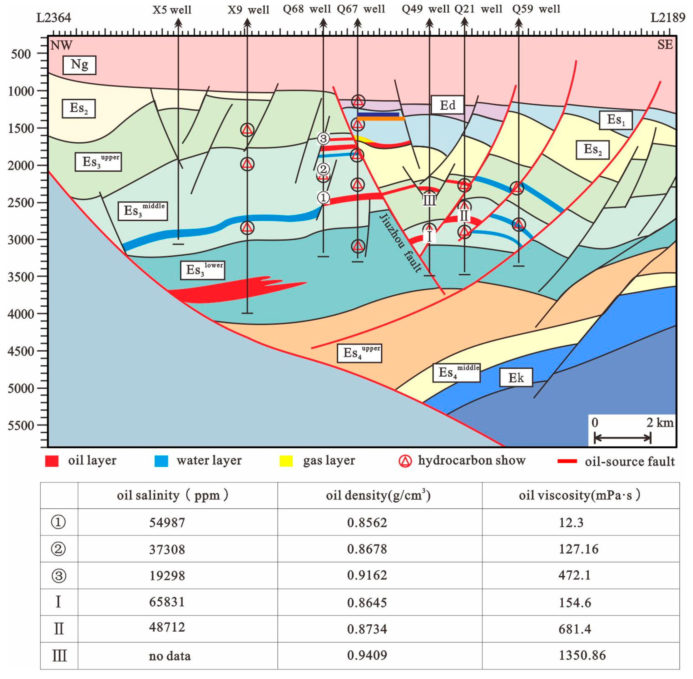
The Langgu Sag is located in the west of the Bohai Bay Basin, where the Paleogene Shahejie and Dongying formations and the Neogene Guantao formation are developed from bottom to top. Previous exploration has shown that the oil and gas in the sag originate mainly from the source rocks in the upper fourth member and the lower third Member of Shahejie Formation (hereinafter abbreviated as Es4U and Es3L, respectively). Meanwhile, the middle third member and the upper third member of Shahejie Formation (hereinafter abbreviated as Es3M and Es3U, respectively) are the main hydrocarbon-enriched horizons. Such a configuration forms a typical ‘lower source, upper reservoir’ type of play. The Langgu sag is characterized by strong tectonic movements and frequent fault activities [42], leading to narrow sedimentary facies bands and rapid facies changes therein. Thus, long-distance lateral migration of oil and gas are rare, especially after vertical migration through oil-source faults. On the plane, oil and gas primarily accumulate in the structural traps on both sides of the fault (Figure 1). After crude oil is oxidized, along the migration path, the density and viscosity of crude oil will decrease, and along the migration path, the salinity of formation water will decrease. The crude oil migration in Langgu Sag was oxidized, therefore along the main fault, both the density and viscosity of crude oil increase from bottom to top, while the salinity content of formation water show a decreasing trend. These features indicate the vertical upward migration of oil and gas, and the oil-source fault is the main transport pathway (Figure 2).
The Jiuzhou fault traverses the Langgu sag with an ~NE strike. It is composed of a 21 km west segment and a 24 km east segment. The dipping angle of the fault is about 75°. The Jiuzhou fault is a long-term active oil-source fault that truncates the Paleogene Shahejie Formation, Dongying Formation, and Neogene Guantao Formation from bottom to top. Oil and gas are enriched on both sides of the fault. However, the along-strike enrichment degree of oil and gas is different, and there is no hydrocarbon accumulation in some structural traps (Figure 1), possibly due to the poor vertical hydrocarbon transport ability in some parts of the fault. Therefore, the effective prediction of the location of the fault’s favorable transport pathways plays an important role in guiding oil and gas exploration in this area.

3. Influencing Factors of the Locations of Favourable Transport Pathways

Different segments of oil-source faults have different transport capacities, leading to differences in hydrocarbon distribution along faults. A large number of studies have shown that oil and gas migration along faults is intermittently episodic under the influence of seismic pumps [26,43], which are affected by the internal structure of faults. For a single fault, the location of its favorable transport pathways is usually related to factors such as the migration force of the fault, the geometry and kinematic characteristics of the fault, and the relationship between the fault activity period and the hydrocarbon accumulation period. Oil-source faults are open when transporting oil and gas, so factors such as shale content in the fault zone and the normal stress of the fault plane are not the main factors controlling the vertical migration of oil and gas [44]. Considering the formation and evolution processes of faults, it is concluded that the development of favorable hydrocarbon transport pathways on oil-source faults is dominantly affected by three factors, including the location of paleo relay ramps before hydrocarbon accumulation, the fault activity intensity during hydrocarbon accumulation, and the location of hydrocarbon transport ridges.

3.1. Location of Paleo Relay Ramps before Hydrocarbon Accumulation

During fault development and segmentation, concentrated stress, highly developed small transfer faults, and fractures are commonly observed in relay ramps, and the development of fractures in the relay ramp is relatively high. When the stress is released in these zones, it is easy to cause earthquakes and formation ruptures, providing pathways for oil and gas migration [45]. The location of relay ramps is often the transition zone in the process of fault evolution and is in a relatively low potential area [46]. Furthermore, the location of relay ramps controls the sand‘s shape [47]. Thus, relay ramp locations not only reflect the direction of oil and gas migration, but also provide favorable conditions for the migration along the fault.
However, not all relay ramps are conducive to the migration of oil and gas. If the formation period of relay ramps is earlier than the hydrocarbon accumulation period, their locations are favorable hydrocarbon accumulation zones. During hydrocarbon accumulation, the location of relay ramps opens prior to other parts of the oil-source fault, facilitating the vertical migration of oil and gas therein. By contrast, if relay ramps form later than hydrocarbon accumulation, the transport ability of their locations is weak and cannot be used as favorable hydrocarbon transport pathways on oil-source faults.

3.2. Fault Activity Intensity during Hydrocarbon Accumulation

Favorable transport pathways of oil-source faults are also affected by the intensity of fault activity after stress release. The spatiotemporal activity of different fault segments are obviously inhomogeneous, resulting in significant differences in oil and gas migration along the fault strike [48]. Faults are the product of tectonic movements, and the greater the intensity of the fault activity, the stronger the tectonic movement it has experienced. Larger fault activity intensity also leads to more energy being released, thereby providing more power for hydrocarbon migration. In addition, the development of secondary faults and fractures is associated with fault activity [22]. The greater the activity intensity, the more developed the secondary faults and fractures, and the higher the opening degree of fractures, which is also conducive to the migration of oil and gas. It should be noted that highly active oil-source faults are not conducive to oil and gas migration at any time. Only areas with source rocks in the strong hydrocarbon expulsion period are favorable oil and gas transport sites. Therefore, the intensity of fault activity during hydrocarbon accumulation is one of the main factors affecting the development of favorable transport pathways.

3.3. Hydrocarbon Transport Ridges of Faults

When oil and gas migrate vertically along the fault, they do not migrate upward uniformly. Due to the uneven fault plane, there exist three forms of hydrocarbon migration: parallel flow, converging flow, and divergent flow, in which converging flow is most conducive to hydrocarbon migration and accumulation [2]. The transport ridge of faults is the line connecting the highest points along the fault plane, and its location is often structurally high and belongs to a relatively low potential area. During the upward hydrocarbon migration along the oil-source fault, oil and gas converge preferentially to the transport ridge, showing a pattern of converging flow. Therefore, transport ridges are also an influencing factor for the development of the favorable transport pathways along the oil-source fault.

4. Method for Predicting the Location of Favourable Hydrocarbon Transport Pathways

4.1. Recognition of Relay Ramps Developed before Hydrocarbon Accumulation

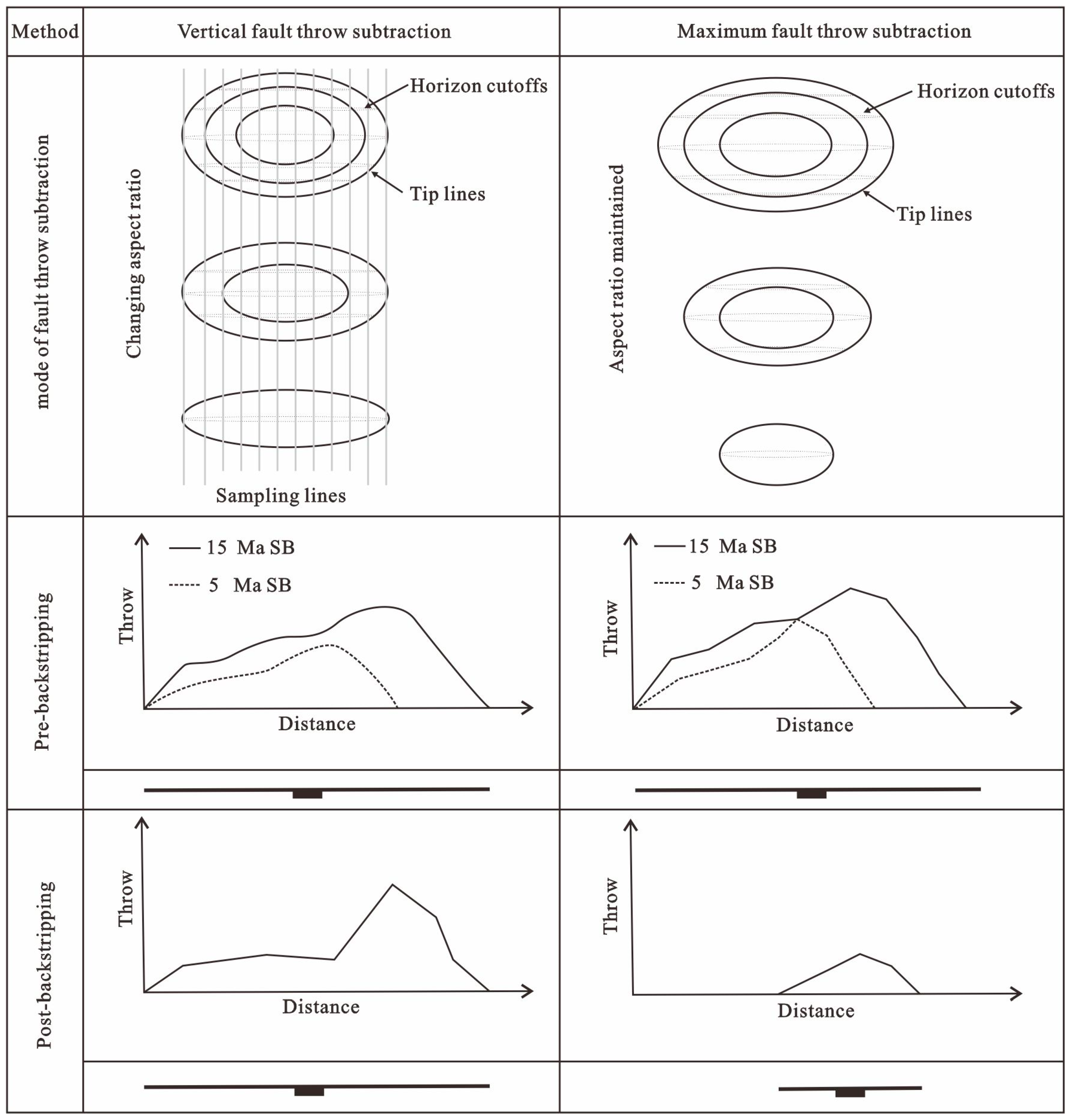
There are multiple approaches for recognizing relay ramps, and the most widely used is the displacement-distance curve. In a displacement-distance curve, the low-value areas represent the relay ramp locations [49,50]. Due to the linear relationship between fault throw and displacement, we used the throw-displacement curve to recognize the location of relay ramps. First, the distribution of paleo fault throws before hydrocarbon accumulation should be restored, and the areas with low values are considered the relay ramps. At present, there are mainly two methods for paleo throw restoration: the vertical fault-throw subtraction method [51,52] and the maximum fault-throw subtraction method [53]. The former refers to the subtraction between the throw of the restored horizon and that of its vertically overlying horizon, while the latter refers to the subtraction between the throw of the restored horizon and the maximum throw in the overlying horizon (Figure 3). Massive statistical data have shown that the maximum displacement of the fault linearly increases with the extension length of the fault [54]. Fault restoration based on the vertical fault-throw subtraction method often results in an increased throw and unchanged length, which has certain limitations. However, the maximum fault-throw subtraction method can more truly reflect the formation and evolution history of faults [55]. Therefore, by restoring the distribution of paleo throws of faults before hydrocarbon accumulation with the method of maximum fault throw subtraction and drawing throw-distance curves, the location of the paleo relay ramps can be effectively identified.

4.2. Determination of Fault Activity Intensity during Hydrocarbon Accumulation

The most commonly used methods for calculating fault activity intensity include the growth index method, the fault throw method, and the fault activity rate method. Among them, the fault activity rate method employs time to measure intensity and has achieved satisfying results in numerous studies [38,40]. Fault activity rate refers to the ratio of fault throw to the corresponding time span in a specific period of geological history. Specifically, different activity rate calculation methods have been proposed for different types of faults [56].
During the calculation process, the hydrocarbon accumulation period should first be determined, followed by the detailed structural interpretation (e.g., horizon and fault interpretations) on the corresponding seismic profiles. Then, the horizon data on both walls of the faults during hydrocarbon accumulation can be read. Meanwhile, the time span of hydrocarbon accumulatio n is obtained according to the stratigraphic timescale of the study area. Finally, the fault activity rate during hydrocarbon accumulation can be calculated using the the method described in the literature [56].

4.3. Determination of the Location of Transport Ridges

A fault is a three-dimensional geological body with a complex internal structure, and the buried fault plane often has an uneven shape. To determine the location where the transport ridges develop, the foremost task is to determine the shape of the fault plane using the corresponding burial depth contours. The lines connecting the depth contours at the low potential points of each horizon are the locations of the transport ridges, manifested as an uplift shape in the buried depth curve.

5. Prediction of the Location of Favourable Hydrocarbon Transport Pathways

The hydrocarbon accumulation in the Langgu sag occurred 34 Ma ago [42]. In this study, by determining the location of the paleo relay ramps, the fault activity rate, and the distribution of hydrocarbon transport ridges at 34 Ma, the location of favorable transport pathways onthe Jiuzhou fault was studied.
Based on seismic data, we employed the maximum fault throw subtraction method to restore the paleo throw distribution of the Jiuzhou fault before 34 Ma (Figure 4). The results revealed three relay ramps in the western segment, which are located at Line 848, Line 1104 and Line 1424, respectively. In the eastern segment, six relay ramps were found, which are located at Line 1616, Line 1712, Line 1840, Line 1968, Line 2128 and Line 2288, respectively. Notably, all these relay ramps are potential favorable locations for faults to transport oil and gas.
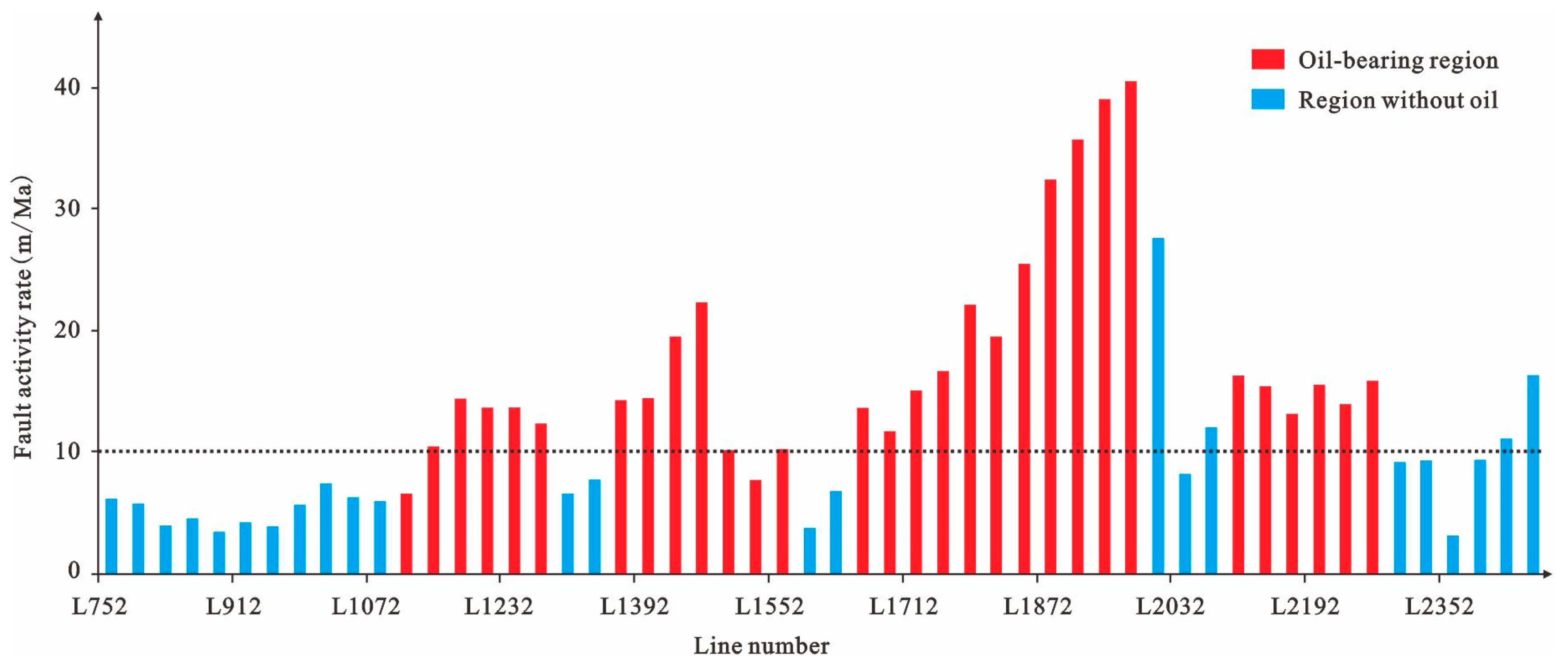
The along-strike fault activity rate during hydrocarbon accumulation shows obvious heterogeneity, with the maximum value reaching 40 m/Ma. Additionally, there are a number of high-value areas in the activity rate. After the comparison between hydrocarbon distribution and fault activity rate, it is evident that oil and gas are mainly distributed on both sides of the fault segments with an activity rate greater than 10 m/Ma, indicating that the greater the intensity of fault activity, the more favorable the vertical migration of oil and gas (Figure 1 and Figure 5).
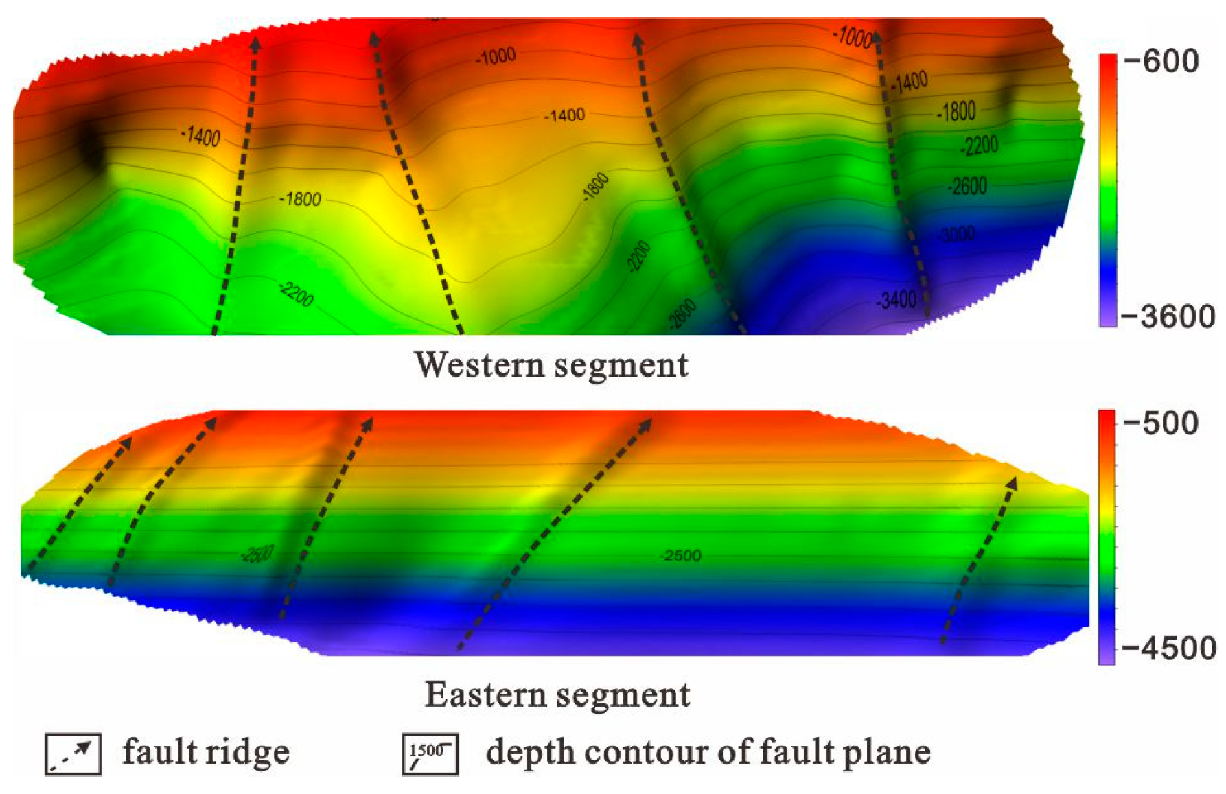
In addition, we read the along-strike burial depth data of different horizons based on 3D seismic data and obtained the corresponding contours of the fault plane depth of the eastern and western fault segments. Finally, four hydrocarbon transport ridges were determined in the western segment (Figure 6), which are located in the vicinity of Line 864, Line 1088, Line 1248, and Line 1376, respectively. Meanwhile, five ridges were found in the eastern segment, which are located near Line 1440, Line 1520, Line 1664, Line 1856, and Line 2224, respectively.
After the superimposition of the three above-mentioned zones (i.e., paleo relay ramps developed before hydrocarbon accumulation, areas with 10 m/Ma fault activity rate during hydrocarbon accumulation, and hydrocarbon transport ridges of the fault), four favorable hydrocarbon transport pathways were revealed (Figure 1). The location of these pathways is in good agreement with the hydrocarbon distribution at present, while the regions without such pathways show less or no oil and gas accumulation, validating the accuracy of the prediction method.

6. Results and Discussion

When a fault is active, the locally formed cavity and fracture system will lead to an explosive increase in permeability. As a result, large-scale hydrocarbon migration will occur along the high-permeability parts of the huge fault system. After the fault activity ceases, hydrocarbons will fall back until the fault closes [57,58]. When the fault activity ceases, the cavity gradually closes under the load pressure from overlying sediments, losing its conductivity. Meanwhile, the permeability of fractures inside the fault fracture zone is one to three orders of magnitude higher than that of the surrounding rock [59]. These fractures are able to transport hydrocarbons, but the scale and efficiency of hydrocarbon migration are much lower than those during the fault activity period.
Hydrocarbon exploration in petroliferous basins shows that oil and gas migration along faults occurs in areas with strong fault activity during hydrocarbon accumulation [40]. Fault activities are frequent in high faulting intensity areas, which are prone to “episode” opening and become the dominant pathways for oil and gas migration [60,61]. Moreover, the rocks in these zones are influenced by stronger forces and are easy to break. Fractures are highly developed and are the key locations for oil and gas to pass through the caprock and migrate vertically [62,63]. Studies have shown that tectonic stress is the direct cause of fault formation and is also an important driving force for oil and gas migration along faults. The greater the intensity of fault activity during hydrocarbon accumulation, the larger the scale of the formed fault cavity and fracture system, and the more conducive it is to hydrocarbon transportation [36].
Previous research results have demonstrated that fault throw can represent the intensity of fault activity, and its size is a key parameter to measure the hydrocarbon transport ability of faults. The larger the fault throw, the larger the width of fault zones and fault rocks [22,64], and the stronger the capacity of faults to transport oil and gas.
The parts where the fault strikes bend and faults intersect with each other are often the regions where the fault relay ramps develop. Natural earthquakes are the most direct evidence of fault activity, and strong earthquakes occur more often at the bending and turning points of faults and in strongly active areas such as the intersection zone of two faults, which have become typically recognized earthquake signs [65]. Due to the growth and connection of fault planes, fault relay ramps become a ridge-like low-potential energy zone, which is conducive to the accumulation of oil and gas and is often the dominant pathway for vertical hydrocarbon migration [37].
Based on both vertical fault and dip-slip fault models, we employed the finite difference numerical simulation method to explore the fault displacement, stress, and expansion changes in fault relay ramps. The results showed that the intersection of faults is the key to the stress concentration and the vertical leakage of the caprock. It is mainly reflected in the following two aspects: First, the stress change causes the overlying caprock to open a triangular high expansion zone near the intersection area, forming a vertical pathway for hydrocarbons to pass through the caprock. Second, under higher strain conditions, the shear strain value in these intersection areas is lower than that of active fault planes. The shear mudstone smearing is low, and the sealing ability is weak. Additionally, at the intersection zones of two or more faults, the rock is strongly stressed and easily broken, thus forming twisted and opening fractures [66].
Fault planes are an uneven geological body, and the upward migration of oil and gas along the fault plane is manifested in three forms: convergent flow, divergent flow, and parallel flow [2]. Among them, the convergent flow is most conducive to upward hydrocarbon migration. Therefore, by describing the shape of the fault plane, one could determine where the ridge develops on the fault plane, and this area may be a favorable pathway for faults to transport oil and gas.
Overall, at different faulting periods, the high faulting intensity parts, the relay ramps, and the ridges of the fault can all become hydrocarbon transport pathways. In this study, we suggest that the region superimposed by paleo relay ramps, high faulting intensity zones, and effective transport ridges are favorable for the development of hydrocarbon transport pathways. This is because the stress in the pre-hydrocarbon-accumulation relay ramps is more concentrated, which is prone to the formation of fractures. During hydrocarbon accumulation, the fault activity intensity is greater, the formed transport pathways are larger in scale, and the driving force for hydrocarbon migration is greater. On the transport ridges, hydrocarbons can migrate along fault planes in the form of convergent flow. Thus, the superimposed regions of the three have favorable conditions for oil and gas to migrate along the faults. Based on this understanding, we predicted the dominant oil and gas transport pathways of the Jiuzhou fault in the Langgu Sag, and the following conclusions have been obtained:
The location of the favorable hydrocarbon transport pathways of the oil-source fault is mainly affected by three factors: the distribution of the paleo relay ramp of the fault before hydrocarbon accumulation, the fault activity intensity during hydrocarbon accumulation, and the location of the fault transport ridge. Particularly, the region superimposed by paleo relay ramps, high faulting intensity zones, and effective transport ridges are favorable for the development of hydrocarbon transport pathways.
Based on 3D seismic data, we utilized the maximum throw subtraction method to restore the pre-hydrocarbon accumulation distribution of paleo fault throws for the purpose of determining the location of the paleo relay ramps. Then, we calculated the fault activity rate during hydrocarbon accumulation, which can represent the intensity of fault activity. Furthermore, the burial depth contour of the fault plane was used to search for the location of hydrocarbon transport ridges. Finally, the above results were combined to determine the location of favorable hydrocarbon transport pathways on the Jiuzhou fault via superimposed display.
A total of four favorable hydrocarbon transport pathways have been determined, and their locations accord well with the current distribution of hydrocarbons.

Author Contributions

Methodology, J.L.; Software, X.H.; Investigation, Y.L. and J.S.; Resources, Y.K.; Data curation, Y.W. All authors have read and agreed to the published version of the manuscript.

Funding

The study is supported by the National Natural Science Foundation of China (No. 42202158, No. 42272166, and No. 42102165).

Institutional Review Board Statement

Not applicable.

Informed Consent Statement

Not applicable.

Data Availability Statement

The data that support the findings of this study are available on request from the corresponding author upon reasonable request.

Acknowledgments

We are grateful for the constructive suggestions given by Guang Fu. We also thank Huabei Oilfield, CNPC for providing relevant data.

Conflicts of Interest

The authors declare no conflict of interest.

References

  1. Price, L.C. Basin richness and source rock disruption: A fundamental relationship. J. Petrol. Geol. 1994, 17, 5–38. [Google Scholar] [CrossRef]
  2. Hindle, A.D. Petroleum migration pathways and charge concentration: A three-dimensional model. AAPG Bull. 1997, 81, 1451–1481. [Google Scholar]
  3. Williams, R.T.; Beard, B.L.; Goodwin, L.B.; Sharp, W.D.; Johnson, C.M.; Mozley, P.S. Radiogenic isotopes record a ‘drop in a bucket’–A fingerprint of multi-kilometer-scale fluid pathways inferred to drive fault-valve behavior. J. Struct. Geol. 2019, 125, 262–269. [Google Scholar]
  4. Caine, J.S.; Evans, J.P.; Forster, C.B. Fault zone architecture and permeability structure. Geology 1996, 24, 1025–1028. [Google Scholar] [CrossRef]
  5. Fu, X.; Xu, P.; Wei, C.; Lv, Y. Internal structure of normal fault zone and hydrocarbon migration and conservation. Earth Sci. Front. 2012, 19, 200–212. [Google Scholar]
  6. Bauer, J.F.; Meier, S.; Philipp, S.L. Architecture, fracture system, mechanical properties and permeability structure of a fault zone in Lower Triassic sandstone, Upper Rhine Graben. Tectonophysics 2015, 647–648, 132–145. [Google Scholar] [CrossRef]
  7. Medina-Cascales, I.; Koch, L.; Cardozo, N.; Martin-Rojas, I.; Alfaro, P.; García-Tortosa, F.J. 3D geometry and architecture of a normal fault zone in poorly lithified sediments: A trench study on a strand of the Baza Fault, central Betic Cordillera, south Spain. J. Struct. Geol. 2019, 121, 25–45. [Google Scholar] [CrossRef]
  8. Delogkos, E.; Manzocchi, T.; Childs, C.; Camanni, G.; Roche, V. The 3D structure of a normal fault from multiple outcrop observations. J. Struct. Geol. 2020, 136, 104009. [Google Scholar] [CrossRef]
  9. Xie, X.; Li, S.; Dong, W.; Hu, Z. Evidence for episodic expulsion of hot fluids along faults near diapiric structures of the Yinggehai Basin, South China Sea. Mar. Petrol. Geol. 2001, 18, 715–728. [Google Scholar] [CrossRef]
  10. Yielding, G.; Freeman, B.; Needham, D.T. Quantitative fault seal prediction. AAPG Bull. 1997, 81, 897–917. [Google Scholar]
  11. Lyu, Y.; Wang, W.; Hu, X.; Fu, G.; Shi, J.; Wang, C.; Liu, Z.; Jiang, W. Quantitative evaluation method of fault lateral sealing. Petrol. Explor. Dev. 2016, 43, 310–316. [Google Scholar] [CrossRef]
  12. Chester, F.M.; Logan, J.M. Implications for mechanical properties of brittle faults from observations of the Punchbowl fault zone, California. Pure Appl. Geophys. 1986, 124, 79–106. [Google Scholar] [CrossRef]
  13. Forster, C.B.; Evans, J.P. Hydrogeology of thrust faults and crystalline thrust sheets: Results of combined field and modeling stud-ies. Geophys. Res. Lett. 1991, 18, 979–982. [Google Scholar] [CrossRef]
  14. Chester, F.M.; Evans, J.P.; Biegel, R.L. Internal structure and weakening mechanisms of the San Andreas Fault. J. Geophys. Res. Solid Earth 1993, 98, 771–786. [Google Scholar] [CrossRef]
  15. Pei, Y.W.; Knipe, R.J.; Paton, D.A.; Douglas, A.; Wu, K. A review of fault sealing behaviour and its evaluation in siliciclastic rocks. Earth-Sci. Rev. 2015, 150, 121–138. [Google Scholar] [CrossRef]
  16. Kim, S.; Ree, J.H.; Han, R.; Kim, N.; Jung, H. Fabric transition with dislocation creep of a carbonate fault zone in the brittle regime. Tectonophysics 2018, 723, 107–116. [Google Scholar] [CrossRef]
  17. Knipe, R.J.; Jones, G.; Fisher, Q.J. Faulting, fault sealing and fluid flow in hydrocarbon reservoirs: An introduction. J. Petrol. Sci. Eng. 1998, 25, 93. [Google Scholar] [CrossRef]
  18. Kim, Y.S.; Peacock, D.C.P.; Sanderson, D.J. Fault damage zones. J. Struct. Geol. 2004, 26, 503–517. [Google Scholar] [CrossRef]
  19. Schueller, S.; Braathen, A.; Fossen, H.; Tveranger, J. Spatial distribution of deformation bands in damage zones of extensional faults in porous sandstones: Statistical analysis of field data. J. Struct. Geol. 2013, 52, 148–162. [Google Scholar] [CrossRef]
  20. Gomila, R.; Arancibia, G.; Mitchell, T.M.; Cembrano, J.M.; Faulkner, D.R. Palaeopermeability structure within fault-damage zones: A snap-shot from microfrac-ture analyses in a strike-slip system. J. Struct. Geol. 2016, 83, 103–120. [Google Scholar] [CrossRef]
  21. Faulkner, D.R.; Lewis, A.C.; Rutter, E.H. On the internal structure and mechanics of large strike-slip fault zones: Field observations of the Carboneras fault in southeastern Spain. Tectonophysics 2003, 367, 235–251. [Google Scholar] [CrossRef]
  22. Childs, C.; Manzocchi, T.; Walsh, J.J.; Bonson, C.G.; Nicol, A.; Schöpfer, M.P. A geometric model of fault zone and fault rock thickness variations. J. Struct. Geol. 2009, 31, 117–127. [Google Scholar] [CrossRef]
  23. Flodin, E.; Aydin, A. Faults with asymmetric damage zones in sandstone, Valley of Fire State Park, southern Nevada. J. Struct. Geol. 2004, 26, 983–988. [Google Scholar] [CrossRef]
  24. Liu, J.; Lv, Y.; Fu, G.; Sun, T.; Li, J. Transporting Models of Oil-Gas Migration by Normal Fault and Its Controlling Effect to Oil-Gas Distribution. J. Jilin Univ. (Earth Sci. Ed.) 2016, 46, 1672–1683. [Google Scholar]
  25. Sibson, R.H.; Moore, J.M.M.; Rankin, A.H. Seismic pumping—A hydrothermal fluid transport mechanism. J. Geol. Soc. 1975, 131, 1081–1090. [Google Scholar] [CrossRef]
  26. Hooper, E.C.D. Fluid migration along growth faults in compacting sediments. J. Petrol. Geol. 1991, 14, 161–180. [Google Scholar] [CrossRef]
  27. Almayahi, A.; Woolery, E.W. Fault-controlled contaminant plume migration: Inferences from SH-wave reflection and electrical resis-tivity experiments. J. Appl. Geophys. 2018, 158, 57–64. [Google Scholar] [CrossRef]
  28. Sun, T.; Fu, G.; Lv, Y.; Zhao, R. A Discussion on Fault Conduit Fluid Mechanism and Fault Conduit Form. Geol. Rev. 2012, 58, 4308–4316. [Google Scholar]
  29. Gudmundsson, A. Fluid overpressure and flow in fault zones: Field measurements and models. Tectonophysics 2001, 336, 183–197. [Google Scholar] [CrossRef]
  30. Liu, J.; Wang, H.; Lyu, Y.; Sun, T.; Zhang, M.; He, W.; Sun, Y.; Zhang, T.; Wang, C.; Cao, L. Reservoir controlling differences between consequent faults and antithetic faults in slope area outside of source: A case study of the south-central Wenan slope of Jizhong Depression, Bohai Bay Basin, NE China. Petrol. Explor. Dev. 2018, 45, 82–92. [Google Scholar] [CrossRef]
  31. Eichhubl, P.; Davatzes, N.C.; Becker, S.P. Structural and diagenetic control of fluid migration and cementation along the Moab fault, Utah. AAPG Bull. 2009, 93, 653–681. [Google Scholar] [CrossRef]
  32. Yan, J.; Luo, X.; Wang, W.; Toussaint, R.; Schmittbuhl, J.; Vasseur, G.; Chen, F.; Yu, A.; Zhang, L. An experimental study of secondary oil migration in a three-dimensional tilted porous medium. AAPG Bull. 2012, 96, 773–788. [Google Scholar] [CrossRef]
  33. Vasseur, G.; Luo, X.; Yan, J.; Loggia, D.; Schmittbuhl, J. Flow regime associated with vertical secondary migration. Mar. Petrol. Geol. 2013, 45, 150–158. [Google Scholar] [CrossRef]
  34. Luo, X. Mathematical modeling of temperature-pressure transient variation in opening fractures and sedimentary for-mations. Oil Gas Geol. 1999, 20, 1–6. [Google Scholar]
  35. Zhang, L.; Luo, X.; Song, G.; Hao, X.; Qiu, G.; Song, C.; Lei, Y.; Xiang, L.; Liu, K.; Xie, Y. Quantitative evaluation of parameters to characterize fault opening and sealing during hydrocarbon migration. Acta Petrol. Sin. 2013, 34, 92–100. [Google Scholar]
  36. Jung, B.; Garven, G.; Boles, J.R. Effects of episodic fluid flow on hydrocarbon migration in the Newport-Inglewood Fault Zone, Southern California. Geofluids 2014, 14, 234–250. [Google Scholar] [CrossRef]
  37. Sun, T.; Fu, G.; Wang, F.; Zhang, L.; Xi, G.; Lv, Y. Control effect of transporting ridge in hydrocarbon accumulation in uplift area outside of source area:A case study of Fuyu oil layer in Xingbei Region, Daqing placanticline. J. Cent. South Univ. (Sci. Technol.) 2014, 45, 4308–4316. [Google Scholar]
  38. Zou, H.; Zhou, X.; Bao, X.; Liu, J.; Teng, C.; Zhuang, X. Controlling factors and models for hydrocarbon enrichment/depletion in Paleo-gene and Neogene, Bohai sea. Acta Petrol. Sin. 2010, 31, 885–893. [Google Scholar]
  39. Fu, Q.; Liu, B.; Xu, C.; Niu, C.; Fu, N.; Zhang, B.; Ding, L. The couple relationship of quantitative analysis of the structures and oil & gas accumula-tion in Huanghekou depression, Bohai Bay Basin. Acta Petrol. Sin. 2013, 34, 112–119. [Google Scholar]
  40. Jiang, Y.L.; Liu, P.; Song, G.Q.; Liu, H.; Wang, Y.S.; Zhao, K. Late Cenozoic faulting activities and their influence upon hydrocarbon accumulations in the Neogene in Bohai Bay Basin. Oil Gas Geol. 2015, 36, 525–533. [Google Scholar]
  41. Wan, G.; Tang, L.; Jin, W.; Yang, W.; Lei, G. Control of salt-related tectonics on oil and gas accumulation in the western Kuqa depression. Acta Geol. Sin. 2007, 81, 187–196. [Google Scholar]
  42. Zhao, X.; Jin, F.; Wang, Q.; Fan, B.; Yang, D. The Secondary Exploration Engineering of Oil-Rich Sag in Graben Basin; Petroleum Industry Press: Bejing, China, 2016; pp. 51–275. [Google Scholar]
  43. Scholz, C.H.; Sykes, L.R.; Aggarwal, Y.P. Earthquake prediction: A physical basis. Science 1973, 181, 803–810. [Google Scholar] [CrossRef]
  44. Zhao, M.; Liu, Z.; Xin, Q.; Cai, Y. Geologic factors for controlling vertical migration of hydrocarbons along faults. J. China Univ. Petrol. (Ed. Nat. Sci.) 2001, 25, 21–24. [Google Scholar]
  45. Wang, W.; Dou, L.; Zhang, Z.; Li, Z.; Li, Q. Transfer zone character and its relationship to hydrocarbon in Fula Sag, Sudan. Petrol. Explor. Dev. 2007, 34, 124–127. [Google Scholar]
  46. Schlische, R.W. Geometry and origin of fault-related folds in extensional setting. AAPG Bull. 1995, 79, 1661–1678. [Google Scholar]
  47. Liao, J.; Wang, H.; Lv, M.; Xiao, J.; Gan, H.; Yan, D. Evolution of syndepositional faulting and its controlling effect on sedimentary filling in Songnan-Baodao sag of Qiongdongnan basin, South China Sea. J. China Univ. Min. Technol. 2016, 45, 336–346. [Google Scholar]
  48. Boles, J.R.; Eichhubl, P.; Garven, G.; Chen, J. Evolution of a hydrocarbon migration pathway along basin-bounding faults: Evidence from fault cement. AAPG Bull. 2004, 88, 947–970. [Google Scholar] [CrossRef]
  49. Peacock, D.C.P.; Sanderson, D.J. Geometry and development of relay ramps in normal fault systems. Am. Assoc. Petrol. Geol. Bull. 1994, 78, 147–165. [Google Scholar]
  50. Giba, M.; Walsh, J.J.; Nicol, A. Segmentation and growth of an obliquely reactivated normal fault. J. Struct. Geol. 2012, 39, 253–267. [Google Scholar] [CrossRef]
  51. Childs, C.; Easton, S.J.; Vendeville, B.C.; Jackson, M.; Lin, S.T.; Walsh, J.J.; Watterson, J. Kinematic analysis of faults in a physical model of growth faulting above a viscous salt analogue. Tectonophysics 1993, 228, 313–329. [Google Scholar] [CrossRef]
  52. Chapman, T.J.; Meneilly, A.W. The displacement patterns associated with a reverse-reactivated, normal growth fault. Geol. Soc. Lond. Spec. Publ. 1991, 56, 183–191. [Google Scholar] [CrossRef]
  53. Rowan, M.G.; Hart, B.S.; Nelson, S. Three-dimensional geometry and evolution of a salt-related growth-fault array: Eugene Is-land 330 field, offshore Louisiana, Gulf of Mexico. Mar. Petrol. Geol. 1998, 17, 309–328. [Google Scholar] [CrossRef]
  54. Kim, Y.S.; Sanderson, D.J. The relation between displacement and length of faults:A review. Earth-Sci. Rev. 2005, 68, 317–334. [Google Scholar] [CrossRef]
  55. David, M.D.; Bruced, D.T. Four-dimensional analysis of the Sembo relay system, offshore Angola: Implications for fault growth in salt-detached settings. AAPG Bull. 2009, 93, 763–794. [Google Scholar]
  56. Wu, Z.; Li, W.; Zheng, D.; Lv, H. Analysis on Features and Origins of the Mesozoic and Cenozoic Faults in Zhanhua Sag. Geol. J. China Univ. 2004, 10, 405–417. [Google Scholar]
  57. Elkhoury, J.E.; Brodsky, E.E.; Agnew, D.C. Seismic waves increase permeability. Nature 2006, 441, 1135–1138. [Google Scholar] [CrossRef]
  58. Elkhoury, J.E.; André Niemeijer Brodsky, E.E.; Marone, C. Laboratory observations of permeability enhancement by fluid pressure oscilla-tion of in situ fractured rock. J. Geophys. Res. Solid Earth 2011, 116, B02311. [Google Scholar] [CrossRef]
  59. Balsamo, F.; Storti, F.; Salvini, F.; Silva, A.; Lima, C. Structural and petrophysical evolution of extensional fault zones in low-porosity, poorly lithified sandstones of the Barreiras Formation, NE Brazil. J. Struct. Geol. 2010, 32, 1806–1826. [Google Scholar] [CrossRef]
  60. Fossen, H.; Rotevatn, A. Fault linkage and relay structures in extensional settings—A review. Earth-Sci. Rev. 2016, 154, 14–28. [Google Scholar] [CrossRef]
  61. Nixon, C.; Vaagan, S.; Sanderson, D.J.; Gawthorpe, R.L. Spatial distribution of damage and strain within a normal fault relay at Kilve, U.K. J. Struct. Geol. 2019, 118, 194–209. [Google Scholar] [CrossRef]
  62. Kim, Y.S.; Sanderson, D.J. Inferred fluid flow through fault damage zones based on the observation of stalactites in carbonate caves. J. Struct. Geol. 2010, 32, 1305–1316. [Google Scholar] [CrossRef]
  63. Peiro, A.; Simón, J.L.; Román-Berdiel, T. Fault relay zones evolving through distributed longitudinal fractures: The case of the Teruel graben system (Iberian Chain, Spain). J. Struct. Geol. 2020, 131, 103942. [Google Scholar] [CrossRef]
  64. Lucca, A.; Storti, F.; Molli, G. Extensional fracture network attribute distribution in faulted thick sandstone strata: Compione Fault, Northern Apennines, Italy. J. Struct. Geol. 2020, 131, 103954. [Google Scholar] [CrossRef]
  65. Zhang, S. Studies of conjugate seismotectonics of the continental earthquakes in China. Earthq. Res. China 1991, 7, 69–76. [Google Scholar]
  66. Gartrell, A.; Zhang, Y.; Lisk, M.; Dewhurst, D. Fault intersections as critical hydrocarbon leakage zones: Integrated field study and numer-ical modelling of an example from the Timor Sea, Australia. Mar. Petrol. Geol. 2004, 21, 1165–1179. [Google Scholar] [CrossRef]
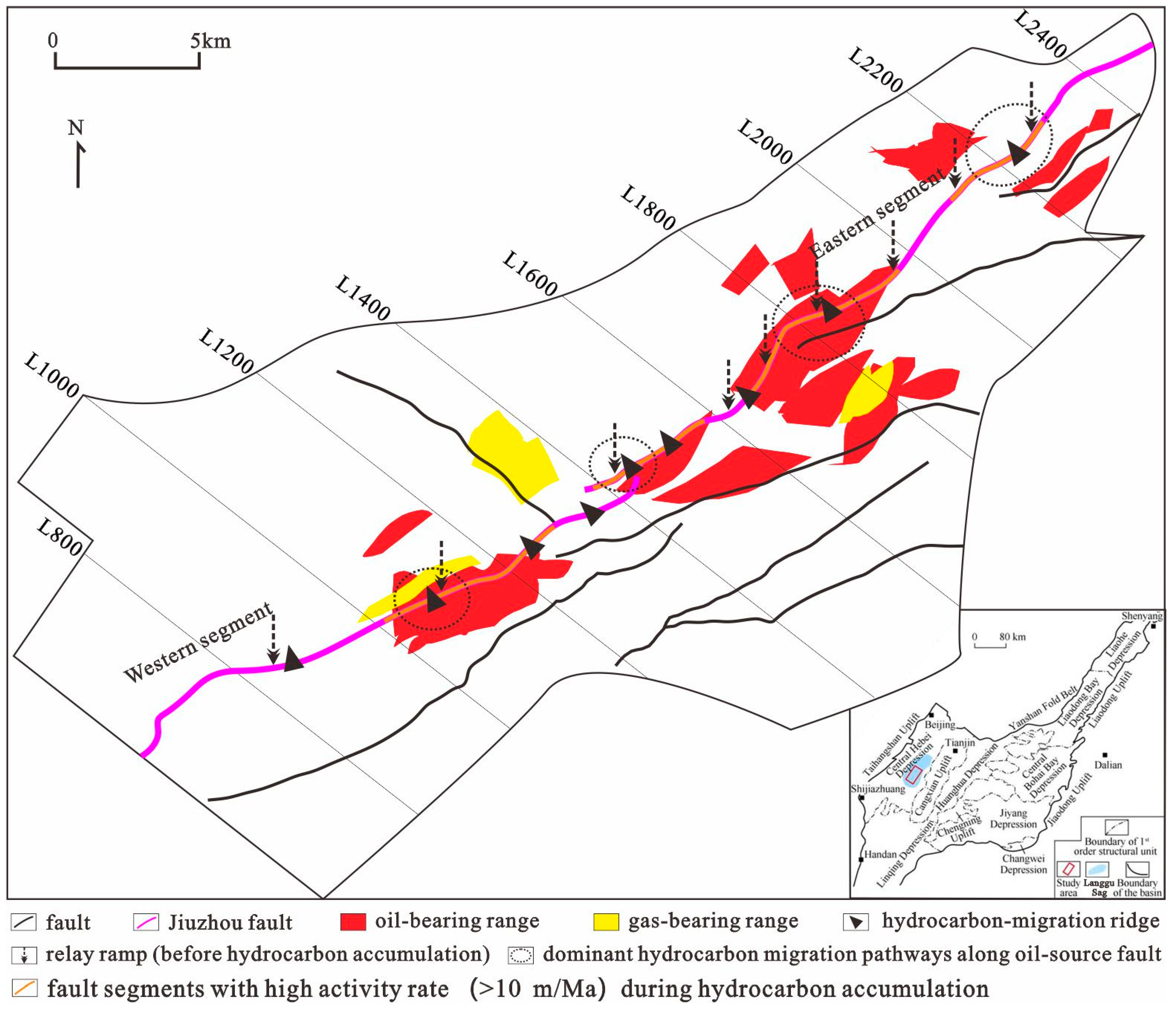
Figure 1. Geological structures and hydrocarbon distribution in the Langgu sag.
Processes 11 01666 g001
Figure 2. Typical hydrocarbon accumulation section of the Langgu sag.
Processes 11 01666 g002
Figure 3. Schematic diagram showing fault throw restoration using two throw backstripping methods.
Processes 11 01666 g003
Figure 4. Throw-distance curves and the backstripping results of the Jiuzhou fault.
Processes 11 01666 g004
Figure 5. Distribution of the activity rate of the Jiuzhou fault during hydrocarbon accumulation.
Processes 11 01666 g005
Figure 6. Distribution of the hydrocarbon migration ridge of the Jiuzhou fault.
Processes 11 01666 g006
Disclaimer/Publisher’s Note: The statements, opinions and data contained in all publications are solely those of the individual author(s) and contributor(s) and not of MDPI and/or the editor(s). MDPI and/or the editor(s) disclaim responsibility for any injury to people or property resulting from any ideas, methods, instructions or products referred to in the content.