Article

The Retention and Control Technology for Rock Beams in the Roof of the Roadway: A Case Study

1
School of Mines, China University of Mining and Technology, Xuzhou 221116, China
2
The State Key Laboratory for Geo Mechanics and Deep Underground Engineering, China University of Mining and Technology, Xuzhou 221116, China
3
School of Mines and Civil Engineering, Liupanshui Normal University, Liupanshui 553001, China
4
Guizhou Guineng Investment Co., Ltd., Liupanshui 551500, China
*
Authors to whom correspondence should be addressed.
These authors contributed equally to this work.
Processes 2023, 11(6), 1593; https://doi.org/10.3390/pr11061593
Submission received: 26 April 2023 / Revised: 15 May 2023 / Accepted: 17 May 2023 / Published: 23 May 2023

Abstract

:
Background: Coal mining requires safe and effective roadway support to ensure production and worker safety. Anchor support is a common method used for controlling the roof of coal seams. This study aims to analyze the effectiveness of different anchor support schemes and provide a theoretical basis for designing safe and effective roadway support. Methods: The authors used a computer simulation tool called FLAC3D to simulate and analyze the spacing between anchor bolts, anchor bolt length, anchor cable length, and effective roadway roof control, and support the schemes at the western wing roadway in the no. 15 coal seam of no. 1 mine of Ping’an Coal Mine. Results: The study found that using different combinations of anchor bolts and cables with varying lengths could effectively control the deformation of the roadway surrounding rock, depending on the spacing between layers of the coal seam. The most effective support schemes were recommended depending on the specific conditions. Conclusion: The study provides a theoretical basis for the design of anchor support in coal mines, which can ensure the safety of production and improve roadway stability. The results could be useful for other mining operations facing similar challenges in roadway support and stability.

1. Introduction

The safe and scientific support of roadways is a key focus in coal mining, and studying the mechanism of anchor bolt support is aimed at understanding the interaction between the anchor bolts and surrounding rock, providing a theoretical basis for anchor support design. Since the introduction of anchor bolts, more than a dozen support theories have been proposed, such as the suspension theory, composite beam theory, and reinforced arch theory. These support theories have played a positive role in production practice. Combined with the roof conditions of the western wing roadway in the no. 15 coal seam of no. 1 mine of Ping’an Coal Mine, the technique of retaining and controlling roof rock beams was proposed, and through theoretical analysis, numerical simulation, and engineering analogies, precise support was carried out in the western wing roadway of the no. 1 mine to meet the production requirements.
One of the most important aspects of mining and tunneling operations is the retention and control technology for the rock beams in the roadway’s roof. It is essential for maintaining the roof’s stability and avoiding accidents that could result in fatalities, injuries, and equipment damage. The literature attempts to give a general overview of the various technologies employed to hold and manage the rock beams in the roadway’s roof. “The mechanisms of instability, deformation behaviors, and support schemes have been the focus of extensive research using various methods, including theoretical analysis, field monitoring, physical model testing, and numerical simulation. Different constitutive models have been proposed by researchers [1,2], Zang et al. (2020) to evaluate the deformation of surrounding rock”. The mechanical characteristics of the rock, the underlying geology, and the logic of the supporting plan play important roles in the stability of the roadway surrounding. In order to support the deep surrounding rock, different support methods are used such as energy-absorbing bolts [3], concrete cribs [4], bolt-grouting [5], and concrete arches [6]. Traditional single-bolt support can no longer provide good supporting effects for deep roadways, [7] and various engineering practices have shown that combining different support methods is an efficient way to manage the stability of the roadway surrounding rock [8,9]. Yang et al. [10] developed a “bolt-cable-mesh-shotcrete + shell” combination support solution to mitigate the significant deformation in deep soft rock roadways. Roadways were supported by the “whole section anchor-grouting” reinforcement technology in areas of loose and broken rock [11]. To manage the severe deformation occurring in deep roadways, a combination supporting system made of foamed concrete and U-shaped steel was used [12].
Similarly, Kang [13] investigated the deformation and damage characteristics of the rocks in coal mine roadways, and introduced the latest developments in roadway support technologies from Germany, the United States, and Australia. The development of roadway support technologies in China, such as rock bolting, steel supports, grouting reinforcement, and combination supports, was also studied in detail. Kang presented four case studies and concluded that rock bolting has become the mainstream roadway support form in China’s coal mines, with other supports also applied as needed. Song et al. [14] reviewed rock bolt technology in underground mining. The authors identified different types of rock bolts, including grouted, friction, mechanical, and cement-based types, and explored their applications in mining operations. Research has shown that the efficiency of rock bolts relies on different factors, including rock type, bolt spacing, and bolt length. The parameters influencing the anchoring effect of rock bolts in tunnels were examined by Li et al. [15]. The results of the study demonstrated that the key elements influencing the efficacy of rock bolts include the bonding strength between the bolt and the surrounding rock, bolt length, and bolt spacing. Similarly, Song et al. [14] conducted a review of rock bolt monitoring techniques for underground mining. The authors identified various monitoring techniques, including load cells, displacement transducers, and acoustic emission, and their effectiveness in assessing the stability of the roof. Wu et al. [16] suggested that an interaction model explains the relationship between the energy-absorbing rock bolt and the rock mass. A semi-analytical solution was produced by this approach, which was developed in Visual Basic. According to the findings, the rock mass can be stabilized by increasing the density of the bolt installations, and the bolt should be installed before the plastic zone is formed. To reinforce rock bolts, Wang et al. [17] carried out an experimental study on the mechanical characteristics of cementitious grout. According to the study, cementitious grout can significantly strengthen the bonding between the bolt and the surrounding rock. Through numerical simulations, the model was verified. According to the field testing and numerical simulations, Zang et al. [18] examined the deformation and failure mechanism of the deep roadway’s surrounding rock in the Tangyang mine. Through simulations and field tests, a combined support system is suggested and evaluated, demonstrating how effectively it can regulate the surrounding rock. The study provides helpful references for deep underground engineering support design. Yu et al. [19] developed a technique to manage the roof during gob-side entrance retaining in tilted coal seams. A supporting system for the roadways was developed based on a simplified mechanical model for the surrounding rocks in various subzones, and the retained gob-side roadway is zoned. Field experiments yielded promising results. He et al. [20] examined support failure and rock deformation during gob-side entry retaining reuse. Results indicate that the advanced abutment pressure has the greatest impact on the surrounding rock failure. Support systems are influenced by multiple dynamic pressures. A project for the stability of a roadway required the application of combined support technology. A combined support technique was developed and applied to a roadway stability engineering project. Liu et al. [21] specifically investigated Panel #11426 of the Xieqiao Mine to better understand the failure mechanism and control technology of the gob-side entry remaining in short-distance coal seams. The study proposes support measures such as building retractable U-steel supports and back-wall filling, and the installation of roof bolts and reinforcement methods. On-site monitoring demonstrated that the outcomes complied with engineering specifications and might serve as a guide for mines with comparable geology. In the numerical study of the reinforcement effect of rock bolts on enhancing the stability of the surrounding rock, Gu et al. [22] concluded that rock bolts can effectively improve the stability of surrounding rock. At the Yuandian no. 2 coal mine, Zhang et al. [23] tested the stability of the roadway surrounding the rock. The study showed that support for bolt grouting could significantly improve the stability of the surrounding rock. Krykovskyi et al. [24] examined how a polymer used to support roofs and shield mines from water inflow and gas emission changed the size and shape of a rock mass area. The study simulates the hardening of the polymer and computes stresses, permeability coefficients, and pressure of the liquid polymeric composition using numerical modeling and the finite element method. The study discovered that the placement of the rock bolts is crucial in order to create a rock–bolt arch, and that the amount of reinforced rock mass relies on the initial permeability value. The results of the study can be used to enhance procedures for supporting mine operating roofs and lowering water inflow and gas emission. In a Kazakhstani mine, Matayev et al. [25] assessed the effectiveness of employing upgraded supports and determined the rock stability. Rock stability categories and physical–mechanical parameters were determined using numerical modeling. The most rational type of fastening, with less material consumption and more dependability, labor productivity, and drifting rate, was discovered to be the combination of rock bolts and shotcrete. The study’s conclusions can be used to plan mining operations and develop robust fastening techniques in related mining businesses. Chehreghani et al. [26] evaluated the stability of the batching room in the Angouran underground mine using a numerical model to determine the best support arrangement. The results indicate that stability must be ensured by a suitable support system. The study proposes that designing a suitable support system is feasible using numerical methods. A strong basis for the efficient control of roadway deformation has been established by the successful implementation of these technologies.
In this paper, the section design support scheme is adopted to achieve safe and efficient production in the mine due to the fact that the working face of no. 15 coal seam 15010 of Ping’an Coal Mine is overlaid with the roadway mining area, and with the increase in mining height, the depth of disturbance and failure of the floor rock mass increases, resulting in the easy breakage of the coal seam roof of the working face and the complex supporting conditions. Although the stability problem in deep roadway engineering has been extensively studied, deformation, failure, and support problems continue to be prevalent due to performance, expense, and technological limitations. This work includes field and numerical simulation research on the deformation failure behavior and support design of deep roadways to address the support problems at the no. 15 coal seam of the no. 1 mine of Ping’an Coal Mine. In a coal mine, as the roadway advances, the distance between the coal seam roof and the overlying roadway mining area becomes smaller and smaller, with a maximum distance of over 10 m and a minimum of less than 2.4 m. The roadway is excavated along the floor, with a coal thickness of approximately 2.1 m. When considering roof support, anchor bolt lengths of 1.8 or 2.4 m and anchor cable lengths of 4.2 or 6.3 m are used. Therefore, in the later stages of design, to provide anchor support for the roof, the distances between the layers are divided into greater than 6.5 m, 4.7 to 6.5 m, 2.5 to 4.7 m, and less than 2.5 m for research and analysis.

2. Principles of Classification of Roof Rock Beam Retention and Control Technology

Principle of Anchor Bolt Support

The core of roadway support theory is a systematic and rational understanding of the essence and laws of the interaction between roadway support and the surrounding rock, especially the support of the roof of the roadway, which has always been a major difficulty in rock engineering research. Currently, the traditional anchoring support theory widely accepted in the mining industry by coal mining technology workers and engineers mainly includes suspension theory, composite beam theory, composite arch theory, maximum horizontal stress theory, rock strength reinforcement theory, etc. These traditional theories apply to different surrounding rock conditions and have been widely used.
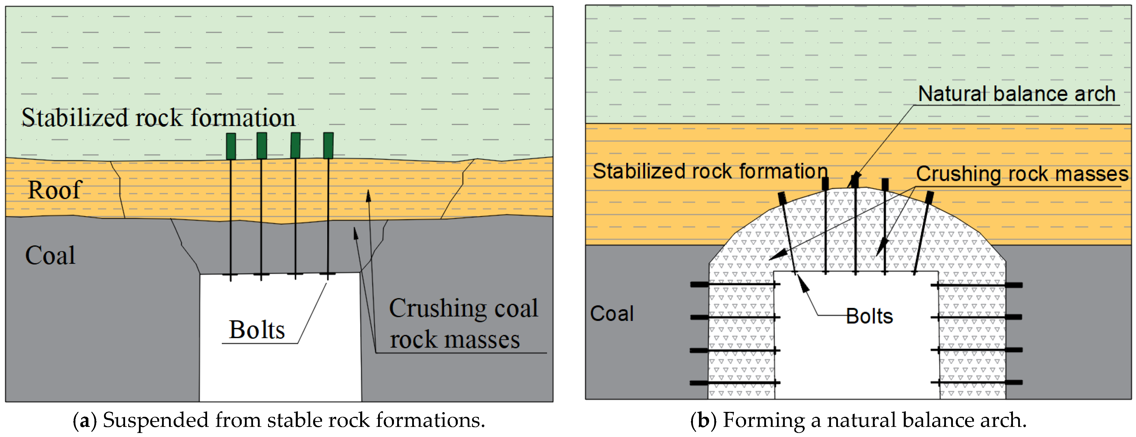
The prerequisite for the implementation of roadway support theory is the study of the stability of the roof rock of the roadway. According to the suspension theory, the function of anchoring support is to suspend the unstable rock layer of the lower part of the roof in the stable rock layer of the upper part. It is the earliest theory of anchoring support and has the characteristics of intuition, easy understanding, and practical use. This kind of support theory is widely used, especially when there are stable rock layers in the upper part of the roof, and loose and broken surrounding rock in the lower part, as shown in Figure 1a. In the relatively weak surrounding rock, after the excavation of the roadway, the stress distribution is redistributed, and a loose and broken zone appears, forming a natural equilibrium arch in the upper part. The function of anchoring support is to suspend the lower loose surrounding rock on the natural equilibrium arch, as shown in Figure 1b.
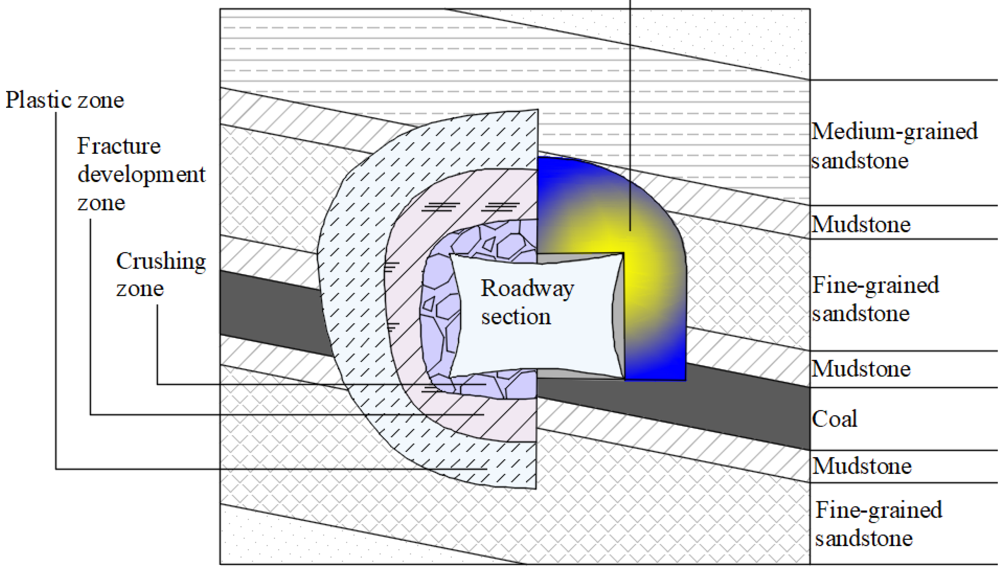
The theory of the anchor composite bearing structure suggests that during the excavation of a tunnel, human engineering disturbance changes the original stress distribution of the rock, providing new space for the surrounding rock of the tunnel to move. The areas closer to the tunnel wall and roof show stress relief, while areas farther away from the tunnel wall and roof show stress concentration. Under the influence of stress and new space, a loose circle of surrounding rock is formed, as shown in Figure 2.
The loose circle of surrounding rock starts from the tunnel wall and roof and proceeds inward. The first zone is the fracture zone, where the rock mass undergoes fracture under engineering disturbance and then converges towards the tunnel under stress. The outer edge of the fracture zone is the fissure development zone, where the deformed rock mass still plays a bearing role on the internal rock mass, and fissures start to develop during the convergence process, but are not completely fractured. This forms the fissure development zone. The surrounding rock in the deeper area of the fissure development zone and fracture zone only undergoes plastic failure under the support of the surrounding rock in the fissure development zone and the fracture zone, without fracturing. This area is called the plastic zone. The plastic zone, fissure development zone, and fracture zone constitute the loose range of the surrounding rock, collectively referred to as the loose circle of the surrounding rock. The rock mass in the area outside the loose circle of the surrounding rock is relatively less affected by engineering disturbance and does not undergo damage.
The reinforced arch theory holds that by installing anchor bolts in loose and fragmented rock layers, a bearing structure can be formed in unstable coal and rock formations. When the distance between the anchor bolts is small enough, a uniform compression zone can be generated in the coal and rock formations, which can bear the load of the fragmented rocks in the upper part of the failure zone, as shown in Figure 3.
Based on previous research, Li et al. [27] proposed a theory of strengthening the surrounding rock strength of the roadway by anchor bolt support. The main points of this theory are: (1) The essence of anchor bolt support is to form an anchoring body through the interaction between the rock mass and the anchoring area of the anchor bolt, forming a unified bearing structure; (2) Anchor bolt support can improve the mechanical parameters of anchoring force, including the mechanical parameters (elastic modulus, cohesive force, internal friction angle, etc.) before and after the failure of the anchoring body, and improve the mechanical performance of the anchored body; (3) The peak strength, post-peak strength, and residual strength of the roadway surrounding rock, as well as the rock mass in the anchorage area, can be enhanced by anchor bolt support; (4) Anchor bolt support can change the stress state of the surrounding rock, increase the confining pressure, improve the bearing capacity of the surrounding rock and improve the support condition of the roadway; (5) After the strength of the surrounding rock anchoring body is enhanced, the range of fractured and plastic zones around the roadway and the surface displacement of the roadway can be reduced, the development of fractured and plastic zones of the surrounding rock can be controlled, which is beneficial to the stability of the roadway surrounding rock.
According to the above theory, the effectiveness of using anchor bolts or cables for roadway support is influenced by factors such as the stability of the surrounding rock, anchor bolt parameters, and anchor bolt spacing. Taking into account the actual situation of the surrounding rock in the west wing of the no. 15 coal seam of the no. 1 mining area of Ping’an Coal Mine, there are roadway mining areas above the 150,110 working face. As the roadway advances, the interlayer spacing between the coal seam roof and the roadway mining area becomes smaller and can range from over 10 m to less than 2.5 m. Due to the variation in interlayer spacing and the possible presence of water accumulation in the overlying roadway mining area, new requirements are proposed for the selection of the length of anchor bolts or cables and the spacing between anchor bolts.
Information on the limitations of these theories, as well as the challenges faced when implementing them in real-world scenarios is as follows:
Suspension theory: The suspension theory only considers the passive tensile effect of the bolt, and does not involve its shear resistance and the change of the overall strength of the broken rock layer. Therefore, the theoretical calculation of the bolt load is relatively large with the actual access.
Composite beam theory: (1) The effective combined thickness of the composite beam is difficult to determine. It involves many factors that affect the keypole support, and there is currently no way to estimate the effective combination thickness more reliably; (2) The effect of horizontal stress on the strength, stability and staggered load of the composite beam is not considered. In fact, in the roadway with large horizontal stress, horizontal stress is the main cause of roof failure and instability; (3) It is only applicable to the layered roof, and only considers the restraining effect of the bolt on separation and sliding, and does not involve the influence of the bolt on the strength, deformation modulus and stress distribution of the rock mass.
Reinforced arch theory: Only the supporting functions of each bolt are simply added to obtain the overall bearing structure of the support system, and there is no in-depth study of the mechanical characteristics and influencing factors of the wrong solid rock mass; (2) There are many influencing factors involved in the thickness of the reinforced arch, and it is difficult to estimate it accurately.

3. Engineering Background of the Pin’an Coal Mine

3.1. Case Study

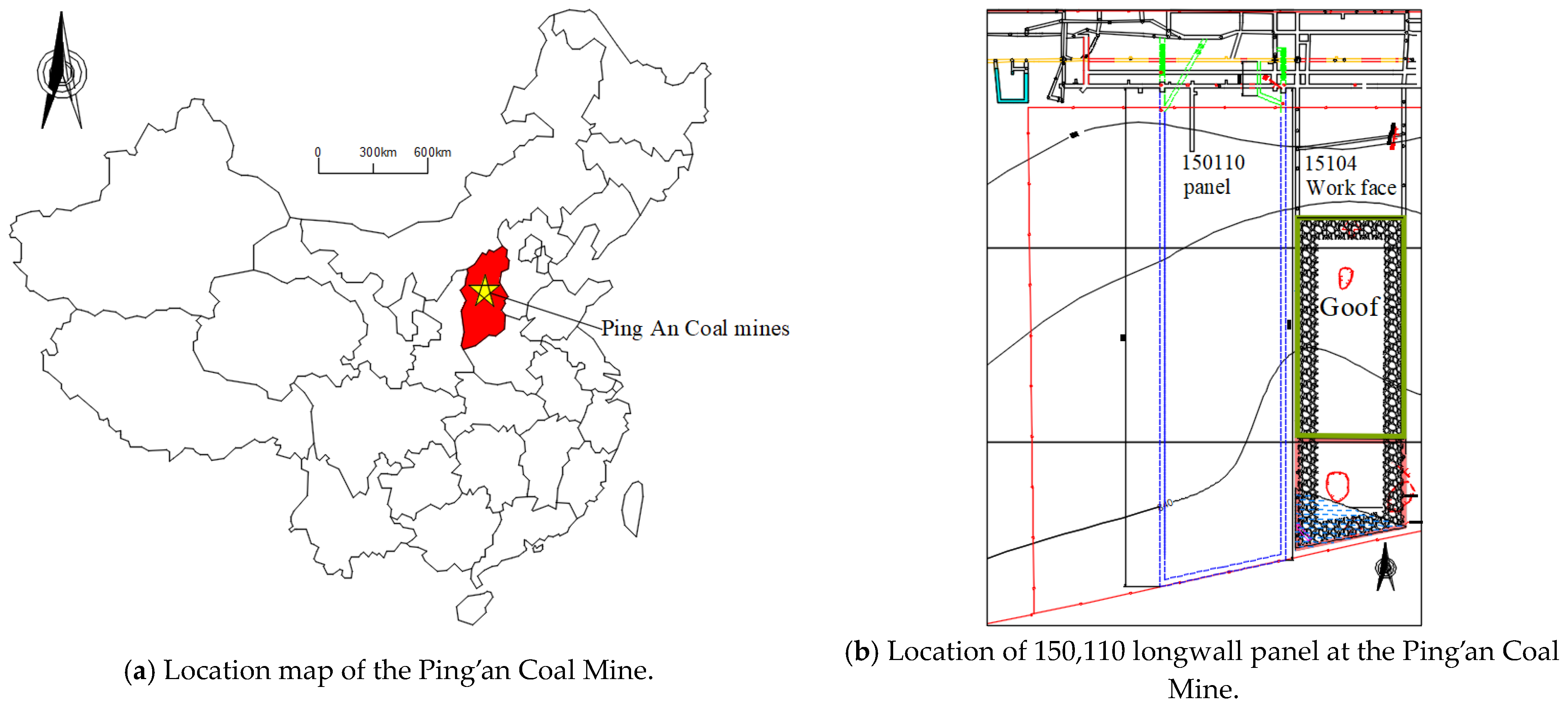
Ping’an Coal Mine is located near Pingshu Village, Pingshu Township, northwest of Shouyang County, Shanxi Province. Figure 4 shows the location map and 150,110 longwall panel with the 15,104 working face at Ping’an Coal Mine. The shape of the coal mine is a polygon, 4.0 km long from east to west, 2.4 km wide from north to south, with an area of 8.4245 km2, batch mining no. 15 coal seam, production scale 900,000 t/a. Batch mining elevation: +989.91 m to +799.9 m.
Ping’an Coal Mine is located on the northern edge of Qinshui Coalfield, the northern part of Shouyang mine Pingtou detailed investigation area, is a low mountainous terrain. The surface is covered by the Fourth Series loess, with the development of soil beams and ditches, and the overall topography is high in the northeast and low in the southwest, with the highest point of the topography located at Dadongliang near the east boundary, elevation 1133.0 m, and the lowest point located at the riverbed in the middle of the south boundary, with an elevation of 1065.2 m, with the maximum relative height difference of 67.8 m. Currently, the no. 15 coal seam of the Taiyuan formation is mainly mined in the mine, which can be explained by the following:
No. 15 coal seam: located in the lower part of the Taiyuan Formation, the lower distance from the no. 15 coal seam is 0 to 2.20 m, with an average of 1.35 m. The thickness of the coal seam is 3.51 to 6.49 m, with an average of 4.93 m. It is a stable and mineable coal seam in the fugitive area, containing 0 to 5 layers of gangue. The structure of the coal seam is simple–complex, with the gangue being mudstone and carbonaceous mudstone. The roof of the coal seam is sandy mudstone, and the floor is mudstone and sandy mudstone. Figure 5 shows the lithological column of the Ping’an Coal Mine.
According to the geological data, the recovery of the adjacent 15,104 face and the drilling results in the west wing of the first mining area, the working faces of 150,110 and 150,112 in the west wing of the first mining area are covered in the roadway mining area, which is affected and the roof of the coal seam is easy to break. With the excavation of the roadway, the maximum distance between the layer spacing of the coal seam roof and the roadway mining area is 10 m to 15 m, the minimum distance is less than 2.5 m, which has an impact on the excavation of the roadway of the two working faces and the re-mining of the working face, and the stagnant water in the roadway mining area will penetrate along the cracks to the lower coal seam, which will soften the lower coal seam. The geological conditions are complex and the roof conditions vary greatly, which requires precise and targeted support solutions.

3.2. Mechanical Parameters of the Surrounding Rock

The properties of the surrounding rock have a large influence on the stability of rock engineering. In order to better understand the surrounding rock conditions, the uniaxial compression test, Brazilian splitting test, and shearing test were performed on rock specimens obtained from the roof, coal seam and floor of the roadway to obtain the rock properties. Figure 6 shows the sandstone specimens collected from the roof of the roadway and anchor bolt and anchor cables, and the physical and mechanical properties of the surrounding rock are listed in Table 1.

4. Numerical Model Development

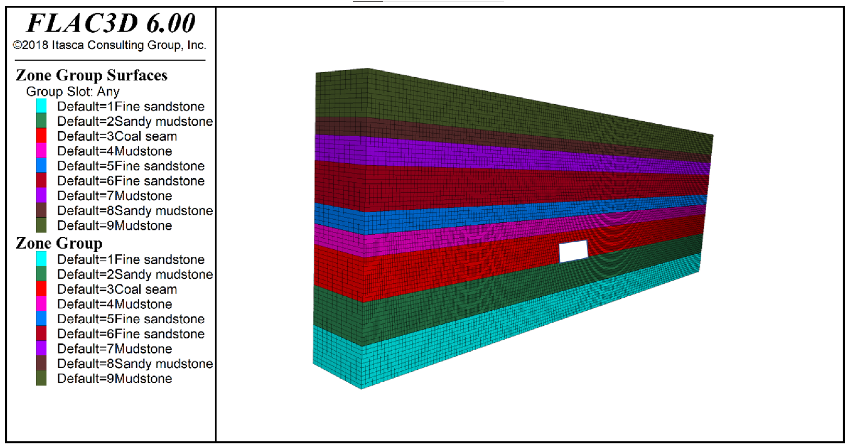
Firstly, based on the analysis of the properties of the roof and floor rocks in Table 1, a roadway model is established. The white area in the figure represents the excavated roadway section, which is 4.7 m wide and 2.9 m high. The model has a length of 100 m and a height of 35 m. The basic roof is represented by the blue part, which is composed of fine sandstone, while the immediate roof is represented by the purple part, which is made up of qualified mudstone. The red part represents coal, and the green part represents the sandstone mudstone floor. The corresponding parameters and Mohr–Coulomb constitutive equations are set for each layer, and the following model is obtained. The frontal view of the numerical model is shown in Figure 7.

4.1. Numerical Analysis of Spacing between Anchors Bolts

As the roadway advances, the spacing between the coal seam roof and the overlying roadway mining area becomes smaller and smaller. The maximum spacing between layers is more than 10 m, and the minimum is less than 2.4 m. The roadway is excavated along the floor, and the thickness of the supported coal seam roof is about 2.1 m. When considering the roof support, anchor bolts with a length of 1.8 m or 2.4 m and anchor cable with a length of 4.2 m or 6.3 m are used. Therefore, in the later design stage, in order to support the roof with anchor bolts and cables, and meet the requirements of anchoring the anchor bolts and cables to the stable rock layer, the distance between layers is divided into four categories for research and analysis, such as being greater than 6.5 m, 4.7 m to 6.5 m, 2.5 to 4.7 m, and less than 2.5 m.
Based on the actual geological conditions of Ping’an Coal Mine, and the changes between the coal seam roof and the overlying mining area during the excavation of the roadway, the support spacing was simulated in two cases: when the layer spacing between the coal seam roof and the overlying mining area was 10 m (using a combination of anchor net and anchor cable with 2.4 m long anchor bolts), and 2.5 m (not using anchor cable and using 1.8 m short anchor bolts). The simulated anchor spacing was 0.8 m, 1 m, and 1.2 m. By analyzing the displacement changes of the roadway’s roof, floor, and two sides, we determined the appropriate anchor support spacing.
The amount of subsidence of the roadway’s roof, floor heave, movement of solid coal pillars, and movement of coal column support was chosen as the analysis objects for the five different spacing scenarios. The relationship between the deformation of the roadway’s surrounding rock and the anchor spacing was analyzed, and the deformation pattern is shown in Figure 8.
According to the figure, when the layer spacing between the no. 15 coal seam roof and the overlying roadway mining area is 10 m, with the increase in the anchor spacing, the deformation of the surrounding rock of the roadway gradually decreases, with the bottom heave being larger, and the deformation of the top and both sides being similar. When the layer spacing is 2.5 m, with the increase in the anchor spacing, the deformation of the surrounding rock of the roadway gradually decreases, showing an overall downward trend. From the perspective of the best support effect for the roadway, when using an anchor net and cable combined support with an anchor bolt length of 2.4 m, a 1000 mm spacing can achieve a more ideal control effect; when not using anchor cables and using short anchor rods of 1.8 m, a 1100 mm spacing can achieve a more ideal control effect. Therefore, when using an anchor net and cable combined support with an anchor bolt length of 2.4 m, the anchor spacing is determined to be 1000 mm; when not using anchor cables and using short anchor bolts of 1.8 m, the anchor spacing is determined to be 1100 mm.

4.2. Numerical Analysis of Anchor Bolt Length

The shorter the anchoring section of the anchor length, the larger the compression area of the anchoring body, and the larger the range of the anchoring body. The greater the preload, the larger the range of the anchoring body. However, the length of the anchoring section has a more obvious effect on the non-anchoring section rock under the surrounding conditions of the roadway surrounding rock. The longer the anchoring section, the smaller the corresponding compression area of the non-anchoring section rock. Therefore, end-anchoring can expand the range of the anchoring body more than full-length anchoring (without preload). However, the adhesive anchoring force of the end anchoring is relatively small and prone to debonding and instability. To solve this problem, segmented anchoring can be used; that is, the inner anchoring section is a fast coil end anchor, and the outer anchoring section is a slow coil full-length anchor. A given preload is applied before the outer section is not solidified, which not only achieves full-length (extended) anchoring, but also applies the preload to the full length of the anchor bolt, solving the contradiction of small compression area and small adhesive anchoring force, expands the range and stability of the anchoring body.
According to the number of anchor bolts used in the past roadway support of Ping’an Coal Mine, the types of anchor agents used in anchor bolt support are MSCK2360 resin cartridge and MSK2360 resin cartridge. One MSCK2360 resin cartridge and one MSK2360 resin cartridge are used for each anchor bolt, and the anchoring effect is good.
Based on the actual geological conditions of the 150,110 longwall panel with the 15,104 working face of Ping’an Coal Mine, during the excavation of the roadway, the distance between the coal seam roof and the upper roadway mining area will gradually decrease, and the maximum interlayer spacing exceeds 10 m, and the minimum is less than 2.5 m, or even smaller. Therefore, when supporting the roof, it is necessary to change the length of the anchor bolt according to the interlayer spacing. When the interlayer spacing is less than 2.5 m, anchor cables cannot be used to support the roof. In order to strengthen the roof support strength, steel shed support also needs to be added. Therefore, numerical simulation is used to study the use of anchor bolts with different lengths for roof support. Based on the existing roadway support parameters, five anchor bolts are arranged in one row for the roof, with a spacing of 1000 mm × 1000 mm, and the roof anchor cable is arranged in a 2-0-2 pattern with a spacing of 2000 mm × 2000 mm. For the rib, three anchor bolts are arranged in one row, with a spacing of 1100 mm × 1000 mm. In this simulation, anchor bolts with lengths of 2.4 m, 2.0 m, and 1.8 m are set according to the actual situation in the mine.
According to the ventilation air return roadway excavation situation of the 150,110 panel, the distance between the coal seam roof and the upper roadway excavation area is about 10 m to 15 m. The layer spacing will gradually decrease in the later stage. To determine the length of the anchor bolt for the roof support reasonably, the length of the anchor rope is considered to be 6300 mm. The roadway in the simulation is excavated along the coal seam floor, and the thickness of the supported coal is about 2.1 m. The layer spacing is set to be greater than 5 m, and the anchor rod lengths are set to be 2.4 m, 2.0 m, and 1.8 m, respectively. The simulation results are shown below.
(1) Characteristics of horizontal stress distribution in the X-axis direction of the surrounding rock of the roadway.
The horizontal stress distribution in the X-axis direction of the surrounding rock of the three schemes is shown in Figure 9.
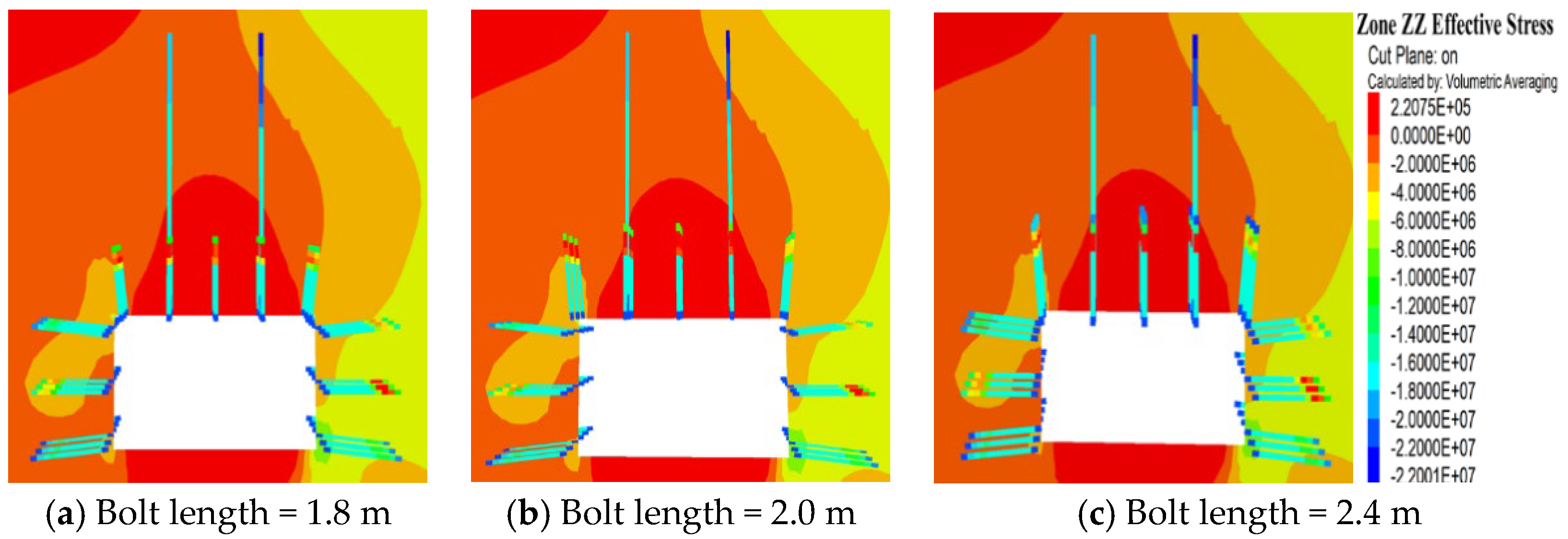
(2) Vertical stress distribution characteristics in the Z-axis direction of the surrounding rock.
The vertical stress distribution in the Z-axis direction of the surrounding rock of the three scheme roadways is shown in Figure 10.
(3) Displacement characteristics of the surrounding rock
The displacement characteristics of the surrounding rock of the three scheme roadways are shown in Figure 11.
Increasing the length of the anchor bolt can effectively increase the anchoring area of the surrounding rock in the roadway, forming a thicker superimposed stress area, thereby improving the mechanical parameters of the rock in the anchoring area of the roadway and better exerting the self-supporting capacity of the surrounding rock. From the simulation results, increasing the anchor bolt length from 1.8 m to 2.4 m reduces the maximum deformation of the roadway from 450 mm to 240 mm, the maximum horizontal stress in the X-axis direction decreases from −24 MPa to −20 MPa, and the maximum vertical stress in the Z-axis direction decreases from −22 MPa to −17 MPa. The plastic zone range of the surrounding rock roof is also significantly reduced, and the influence of anchor bolt length on the plastic zone range of both sides and the bottom plate is relatively small. Therefore, during the excavation process of the roadway in the west wing of the working face of the no. 15 coal seam, when the distance between the coal seam roof and the roadway excavation area is large and the use of 2.4 m long anchor bolts is feasible, it is proposed to consider using 2.4 m long anchor bolts first to achieve the best supporting effect, which is conducive to controlling the deformation of the surrounding rock in the roadway and reducing the degree of stress concentration.
As the excavation of the roadway in the 150,110 working face continues, the distance between the roadway excavation area and the coal seam roof may become increasingly closer, with the shortest distance possibly less than 2.5 m. When the distance between the coal seam roof and the roadway excavation area is small, the roadway roof may be more prone to fragmentation. Due to the prolonged existence of the overlying roadway excavation area, there may be many cracks in the roadway roof. To determine the appropriate length of the anchor bolt, the distance between the coal seam roof and the roadway excavation area is set to 2.5 m, with the roadway excavation area being 0.5 m above the coal seam floor and the thickness of the supporting coal seam being 2.5 m. The anchor bolt lengths are set to 2.4 m, 2.0 m and 1.8 m, and the simulation results are shown below.
(1)
Characteristics of the horizontal stress distribution in the X-axis direction of the surrounding rock.
The horizontal stress distribution in the X-axis direction of the surrounding rock in the three schemes is shown in Figure 12.
(2)
Vertical stress distribution characteristics in the Z-axis direction of the surrounding rock.
The vertical stress distribution in the Z-axis direction of the surrounding rock of the three schemes, the roadway, is shown in Figure 13.
(3)
Displacement characteristics of the surrounding rock.
The displacement characteristics of the surrounding rock of the three scheme roadways are shown in Figure 14.
When the distance between the roof of the coal seam and the overlying roadway excavation layer is less than 2.5 m, due to the small gap between the layers, the roof of the coal seam is prone to cracking and fragmentation. During the process of increasing the length of the anchor from 1.8 m to 2.4 m, the maximum displacement of the roof coal seam and the rib is about 15 to 20 cm. Since the roadway is located above the roadway excavation area, the surrounding rock stress is partially released, with a maximum horizontal stress of about 2.5 MPa and a maximum vertical stress of about 0.5 MPa. Because the layer spacing is 2.5 m, using anchor bolts that are 2.0 m or 2.4 m long can easily cause the roadway to connect with the roadway excavation area, leading to water accumulation or harmful gas influx into the roadway. Therefore, when the layer spacing between the top coal seam and the roadway excavation area is 2.5 m, it is proposed to use 1.8 m long anchor bolts to support the roof coal seam and reinforce the support with steel sheds to enhance the strength of the roof coal seam support and prevent coal from falling.
In summary, both the reasonable length and spacing of the anchor bolts are equally important. In this simulation, there are two different layer spacings, such as 10 m and 2.5 m, chosen for simulation based on the different layer spacings between the coal seam roof and the overlying roadway excavation layer. The change in rock stress during the support of the roadway was examined when the length of the roof coal seam anchor bolt altered from 1.8 m to 2.0 m and 2.4 m. It was found that when the layer spacing was 10 m, using a 2.4 m long anchor bolt with an anchor cable for roof coal seam support could efficiently control the coal seam roof, and the deformation degree of the roadway surrounding rock was relatively small. When the layer spacing was 2.5 m, using a 1.8 m long anchor bolt with a steel shed for coal seam roof support could efficiently control the coal seam roof. According to the engineering analogies, when the layer spacing is less than 2.5 m, using a 1.8 m long anchor bolt with a steel shed support can effectively control the roadway coal seam roof. When the layer spacing is between 2.5 m and 4.7 m, using a 2.4 m long anchor rod with a frame shed support can effectively control the roadway coal seam roof. When the layer spacing is greater than 4.7 m, a combination of anchor bolts and anchor cables can be used, and using a 2.4 m long anchor bolt with an anchor cable support can effectively control the roadway roof of the coal seam.

4.3. Numerical Analysis of Anchor Cable Length

Anchor cables have the characteristics of high anchoring depth, high bearing capacity, and the ability to apply large prestress, which can achieve a relatively ideal support effect. The prestress field of the anchor cable support is the stress field generated by the prestress of the anchor cable in the surrounding rock. It is mainly manifested in that with the increase in the anchor cable length, the range of the effective compressive stress zone gradually increases the height direction, but the change in the width direction is not obvious, and there is a trend of decrease with the increase in the anchor cable length. With the increase in the anchor cable length, the compressive stress of the upper part of the anchor cable and the surrounding rock between the anchor cables gradually decreases. When the prestress is constant, the active support effect of short anchor cables is better than that of long anchor cables, and the greater the length of the anchor cable, the greater the prestress applied. According to the current level of prestress, it is not suitable for the anchor cable to be too long, and it is more reasonable to choose a length of 4 m to 6 m.
Combined with the roof conditions of the roadway in the west wing of the no. 15 coal mining area of Ping’an Coal Mine, the control effect of anchor cables with a length of 5.5 m and 6.3 m on the roof is determined. The stress distribution and displacement of the surrounding rock in the roadway are analyzed and studied by numerical simulation. In the simulation, the length of the roof anchor bolt is 2.4 m, arranged in a row of five, with a spacing of 1000 × 1000 mm between rows, and the length of the side anchor bolt is 1.8 m, arranged in a row of three, with a spacing of 1100 × 1000 mm between rows. The spacing between anchor cables is 2000 × 2000 mm, and the 2-0-2 arrangement is adopted. When the distance between the coal seam roof and the roadway excavation face is 10 m, a 6.3 m anchor cable is used for support in the simulation, and when the distance is between 4.7 m to 6.5 m, a 5.5 m anchor cable is used for support. The simulation results are shown below.
(1)
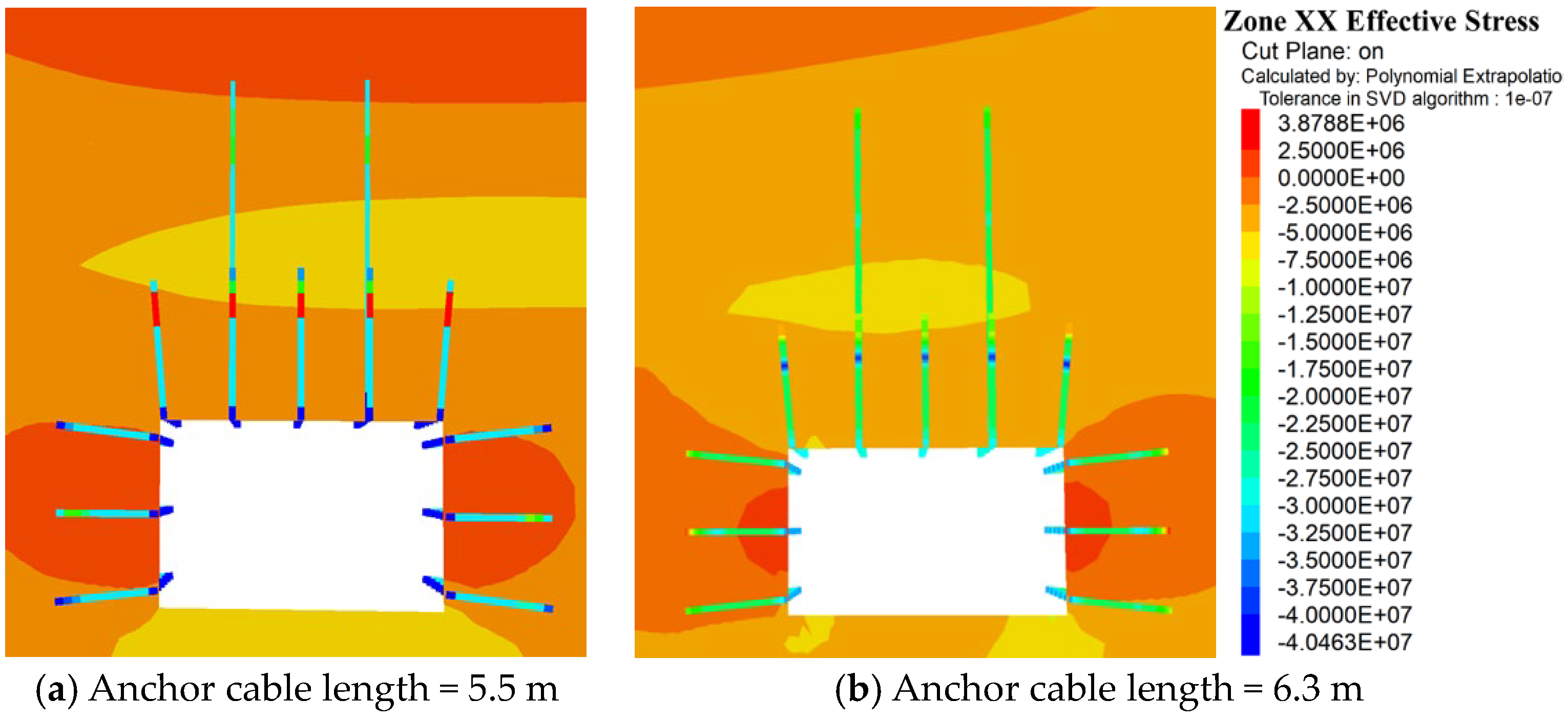
Characteristics of the horizontal stress distribution of the surrounding rock in the X-axis direction.
The horizontal stress distribution of the surrounding rock in the X-axis direction of the three schemes is shown in Figure 15.
(2)
Vertical stress distribution characteristics in the Z-axis direction of the surrounding rock.
The vertical stress distribution in the Z-axis direction of the surrounding rock of the three scheme roadways is shown in Figure 16.
According to Figure 15 and Figure 16, when the distance between the coal seam roof and the roadway excavation face satisfies the use of anchor cables, the use of anchor bolts and anchor cables to support the roof can enhance its stability. Suspension stabilization of the pressure arch formed by the anchor bolt is achieved by using anchor cables with lengths of 5.5 m and 6.3 m. Since the overlying strata are roadway excavation faces, the horizontal stress in the roadway roof is partially released and is approximately 2.5 MPa to 4.0 MPa, while the vertical stress is about 1.0 MPa to 2.0 MPa. In the simulation results, the vertical displacement of the roof is small, about 10 cm, and the deformation of the roadway roof is also small. When the distance between the coal seam roof and the roadway excavation face is greater than 6.5 m, using a 6.3 m anchor cable can effectively support the roof, while when the distance is between 4.7 m to 6.5 m, using a 5.5 m anchor cable can effectively stabilize the roof.
Therefore, when supporting the roadway excavation face of working face 150,110, if the distance between the layers satisfies the conditions for using anchor cables, using anchor bolts and anchor cables with lengths of 5.5 m or 6.3 m to support the roof can effectively control its deformation.

4.4. Proposed Roadway Roof Control and Support Schemes

The roadway design in this study includes four roadways for the belt and ventilation in the 150,110 working face. Based on the mining conditions of the adjacent 15,104 working face and the excavation status of the belt roadway in the 150,110 working face, it is known that there is a roadway excavation face in the overlying strata, and the roof of the no. 15 coal seam is prone to breakage under mining influence. As the roadway advances, the distance between the roadway and the excavation face becomes closer, with a maximum distance of 10 m to 15 m and a minimum distance of less than 2.5 m. To safely and scientifically support the roadway, considering the layer spacing between the coal seam roof and the excavation face and the characteristics of the roof strata, and considering that the length of the anchor bolt is 1.8 m or 2.4 m and the length of the anchor cable is 5.5 m or 6.3 m, four roof control and support schemes are proposed, as shown in Table 2.
This design is based on analogizing the adjacent 15,104 working face support situation and combined with the actual situation of the 150,110 working face to determine the design parameters. In the design, the cross-section of the roadway is rectangular with a gross width of 4.7 m, gross height of 2.9 m, and gross section of 13.63 m2. The net width is 4.5 m, the net height is 2.8 m, and the net section is 12.6 m2. The roadway is excavated along the coal seam floor with an average thickness of 5.02 m, and the gross height of the roadway is 2.9 m, resulting in the presence of supporting coal. The interlayer distance refers to the distance between the no. 1 and no. 15 coal seam roof and the overlying roadway excavation area.

4.4.1. Support Scheme for Layer Spacing Greater Than 6.5 m

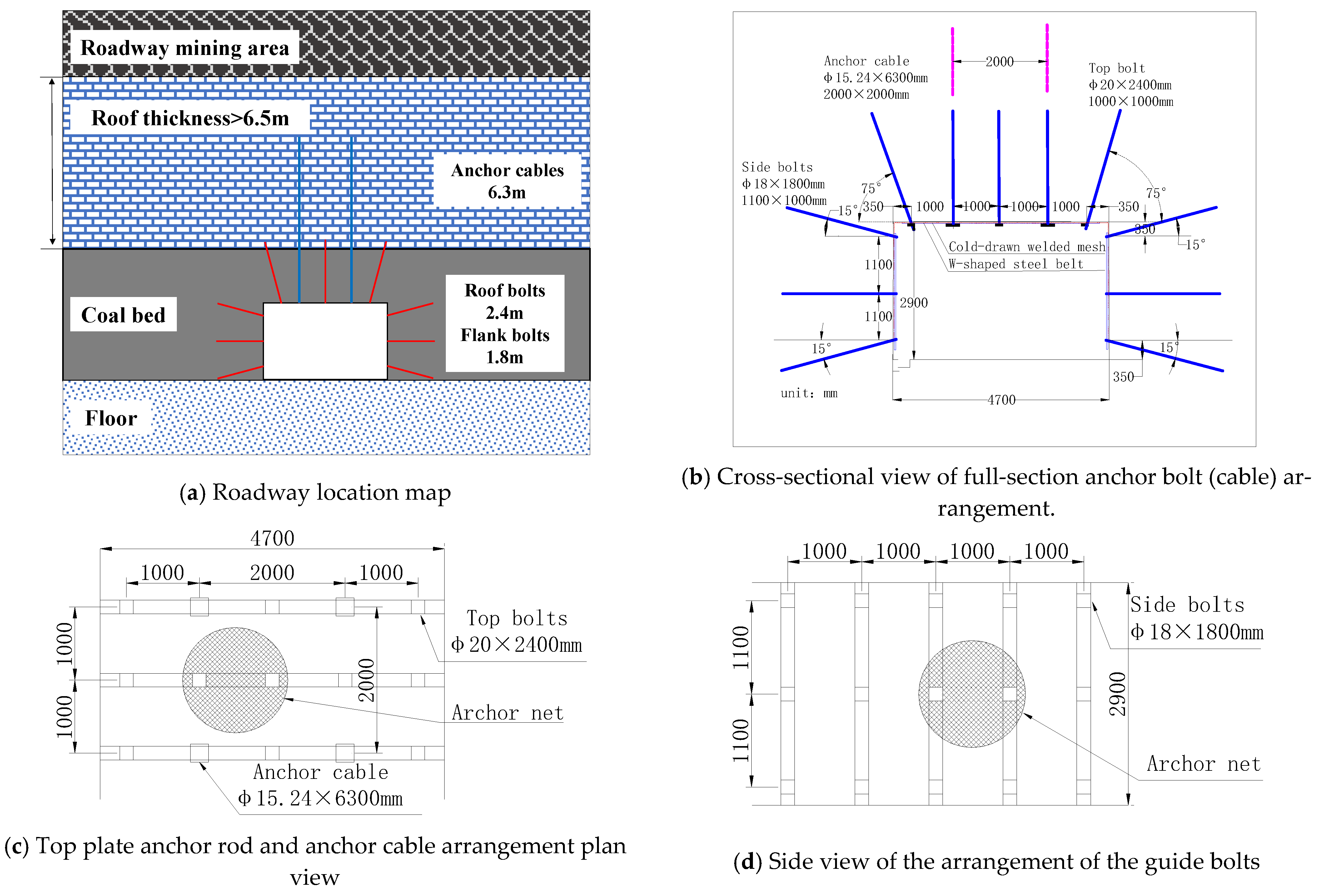
When the distance between the coal seam and the overlying “mining area” is above 6.5 m, the roadway is excavated along the floor, and the thickness of the supported coal is about 2.1 m. An anchor net and cable are used for support, and a 6.3 m long steel strand is selected for the anchor cable to ensure that the anchor point is fixed in a stable rock layer. The material and specifications of anchors, nets, and cables can use existing support materials, and the support parameters follow the current anchor net support parameters, as shown in Figure 17.

4.4.2. Support Scheme for Layer Spacing of 4.7 m to 6.5 m

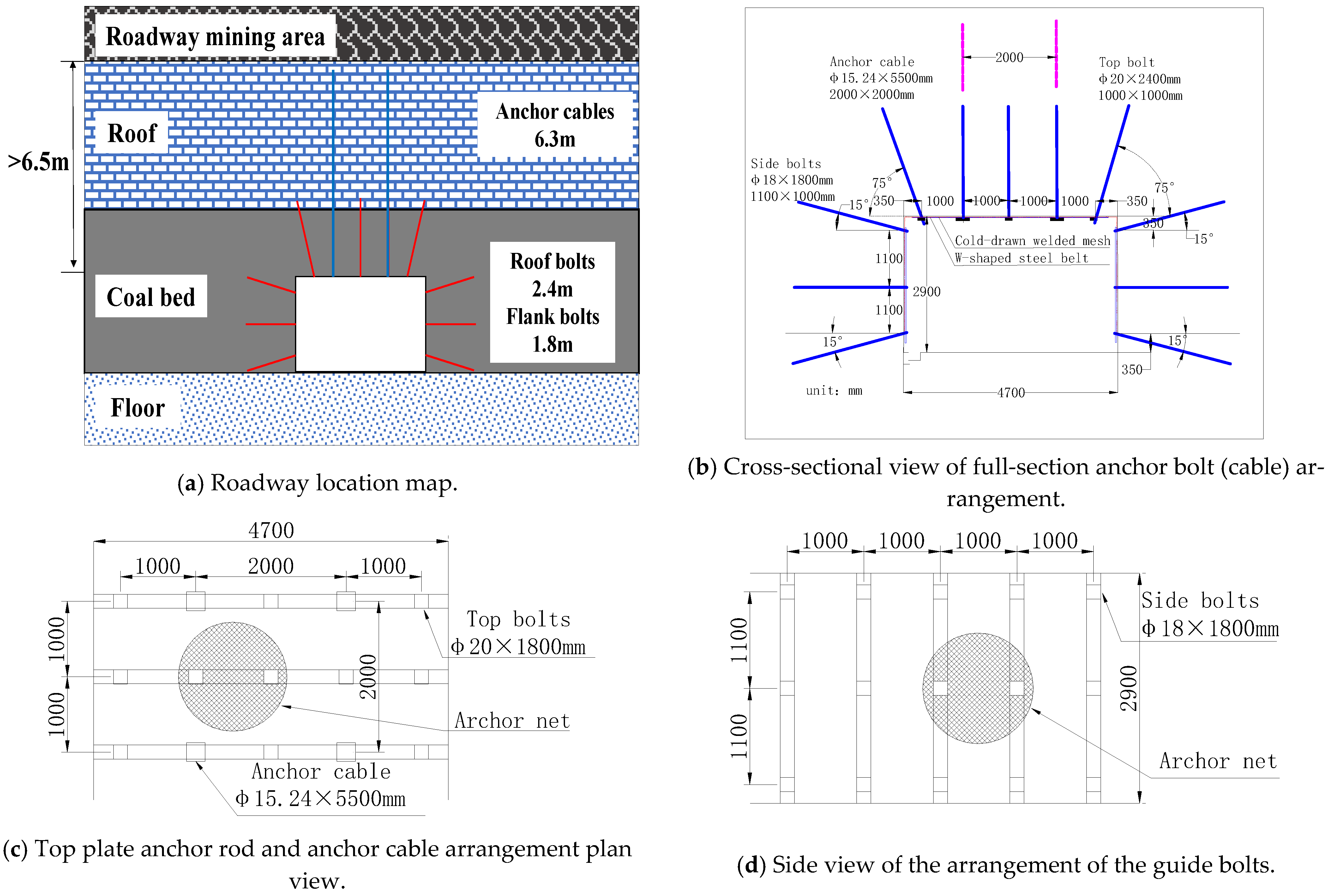
When the spacing between the coal seam and the overlying “roadway mining area” is 4.7 m to 6.5 m, the roadway is excavated along the floor and the roof coal thickness is about 2.1 m. An anchor net and cable are used for support, and 5.5 m long steel strand cables are used for anchoring. It is ensured that the anchoring end of the cable is anchored in the stable rock layer. The materials and specifications of anchors, nets, and cables can use existing support materials, and the support parameters are executed according to the current anchor net support parameters, as shown in Figure 18.

4.4.3. Support Scheme for Layer Spacing of 2.5 m to 4.7 m

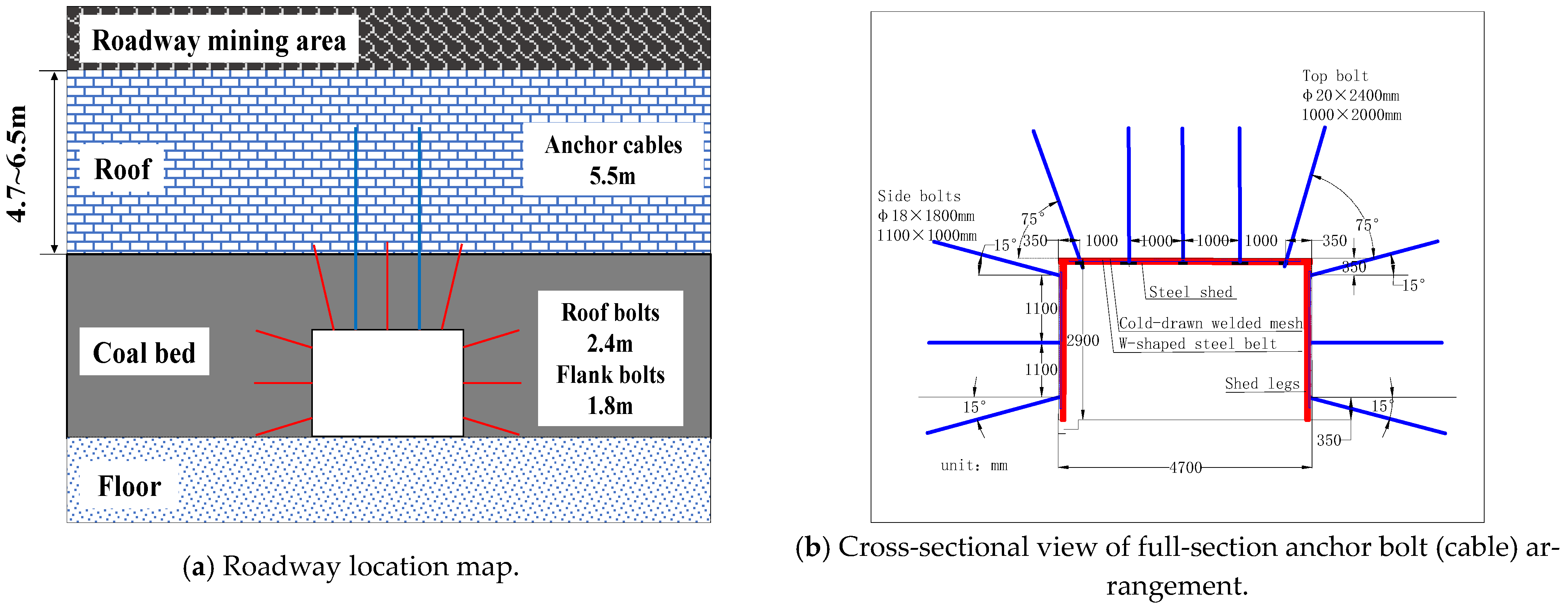
When the distance between the coal seam and the overlying roadway excavation layer is between 2.5 to 4.7 m, the roadway should be excavated along the coal floor with a thickness of about 2.1 m, and the support method used should be a combination of anchor bolts and steel shed support. When supporting the roof, anchor cables should not be used. Instead, a steel shed support made of 2.4 m long anchor bolts, anchor nets, and no. 14 industrial and mining steel should be used. The anchor bolts should be spaced at 1000 mm × 2000 mm and arranged in a staggered pattern with the steel sheds. The support in the middle section should be the same as the existing support method. The materials and specifications of the anchors, nets, and cables should be the same as the existing support materials, as shown in Figure 19.

4.4.4. Support Scheme for Layer Spacing Less Than 2.5 m

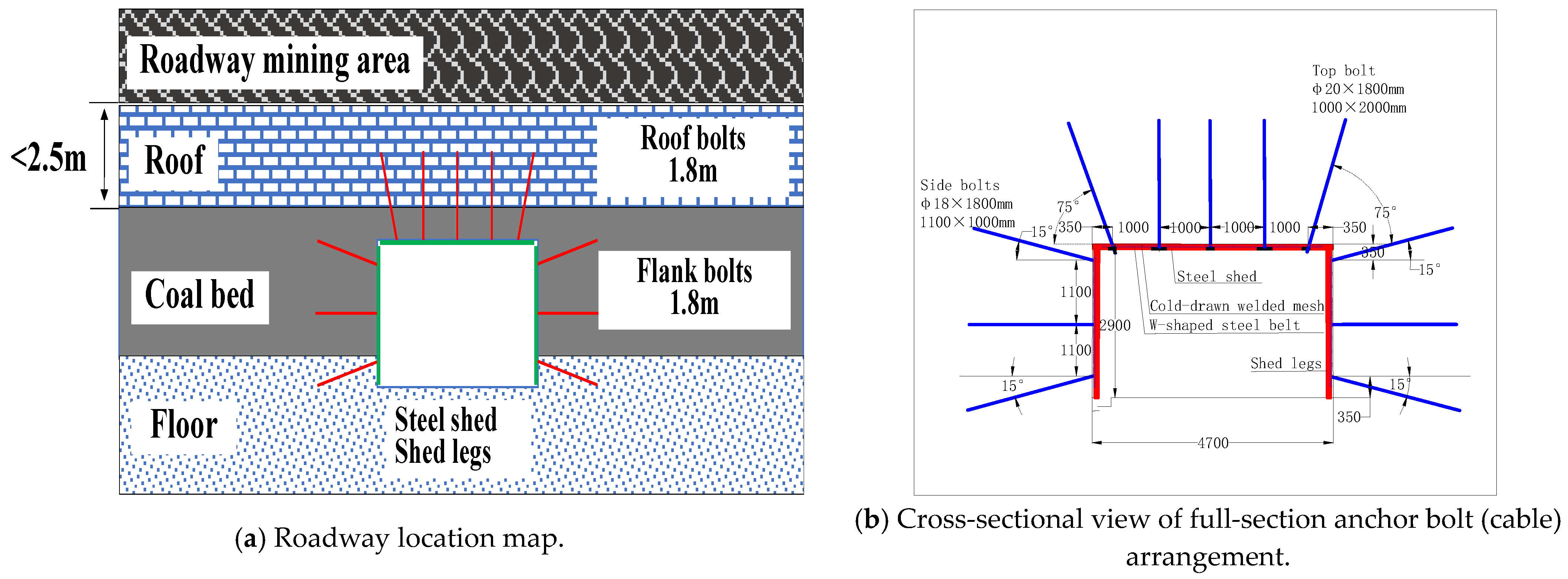
When the distance between the coal seam and the overlying roadway is less than 2.5 m, to ensure the thickness of the anchoring support for the roadway roof, the construction plan of retaining the roof coal and breaking the floor must be adopted. It is necessary to ensure that the distance between the roadway roof and the roadway mining area is not less than 2.5 m, so that the roof has a certain thickness to play a bearing role. At this time, the support method is anchor bolt + anchor net + steel shed support. The length of the roof anchor bolt is 1.8 m, and the steel shed and shed legs are made of no. 14 industrial and mining steel. The spacing between the roof anchor rods is 1000 mm × 2000 mm, and they are arranged staggered with the steel shed. The material and specifications of the anchor, net, and cable for the help support are the same as the existing support materials, as shown in Figure 20.
This part puts forward a specific implementation plan for the section support of the 150110 roadway of Ping’an Coal Mine. The roof thickness is divided into four support schemes according to more than 6.5 m, 6.5 to 4.7 m, 4.7 to 2.5 m and less than 2.5 m. Under the premise of controlling costs, the safety of roadway construction and the stability of surrounding rock control of Ping’an Coal Mine 150,110 are greatly improved, and it is worth engineering analogy with roadway with similar conditions. However, new problems were also discovered during construction:
1. The weakening effect of the water on the roof plate is further revealed, and it may be necessary to optimize the support scheme of some sections.
2. The new borehole revealed a new seam 6.0 m above the trough with a thickness of about one meter, and we recommend a length of 8.0 when the seam thickness is less than 1.0 m, diameter φ 15.24 mm anchor cable for support. When the coal seam exceeds 1 at 0 m, it is recommended to use an anchor cable with a length of 10.0 m and a diameter of φ17.8 mm for support. In order to avoid the anchoring section of the anchor cable in the coal seam, the supporting effect is weakened.
Roadway rock control is a dynamic scheme design that requires continuous optimization. While we are supporting, the geological conditions are in a dynamic change process, so a timely and flexible selection and optimization of support solutions is an important guarantee for safe production.
5. Conclusions

This paper presents a case study on the retention and control technology for rock beams in the roof of the west wing roadway in the no. 15 coal seam of the no. 1 mine of Ping’an Coal Mine to regulate the stability of the surrounding rock of deep roadways. The characteristics of the rock mass were initially assessed using information from field observations and laboratory test results. Then, using the geological location of the 150,110 working face to construct the FLAC3D model, the spacing between anchor bolts, anchor bolt length, anchor cable length, and effective roadway roof control and support schemes were examined. The two different layer spacings of 10 m and 2.5 m were selected for simulation based on the different layer spacings between the coal seam roof and the overlying roadway excavation layer. The change in rock stress during the support of the roadway was studied when the length of the roof coal seam anchor bolt changed from 1.8 m to 2.0 m and 2.4. Similarly, anchor cables with lengths of 5.5 m and 6.3 m were used. Furthermore, four roof control and support schemes are proposed to safely and scientifically support the roof of the roadway, taking into account the characteristics of the roof strata, the layer spacing between the coal seam roof and the excavation face, the length of the anchor bolt at 1.8 or 2.4 m, and the length of the anchor cable at 5.5 or 6.3.
The technical plan must be designed to accommodate the alterations in the roof conditions. Nonetheless, the underlying design principle can offer valuable insights for devising support plans for roadways in overlying mining regions.
Taking into account the advantages of the mine and the current production scenario, the support technology employed in this study is relatively conventional. It falls under the category of optimizing traditional support methods, which implies that there is a lack of innovation. There are several unexplored avenues for innovation that could enhance safety measures and decrease production costs further.

Author Contributions

Conceptualization, N.M.S. and X.W.; methodology, N.M.S. and X.W.; software, J.W. and Y.W.; validation, N.M.S.; formal analysis, C.C. and Y.W.; investigation, N.M.S.; resources, X.Z.; data curation, C.C. and Z.R.; writing—original draft preparation, N.M.S.; writing—review and editing, X.Z.; visualization, J.W.; supervision, X.Z.; project administration, X.Z.; funding acquisition, X.Z. All authors have read and agreed to the published version of the manuscript.

Funding

This research was funded by the “Graduate Innovation Program of China University of Mining and Technology” (grant number 2022WLJCRCZL025). This research was funded by the “Postgraduate Research and Practice Innovation Program of Jiangsu Province” (grant number KYCX22_2629). No additional external funding was received for this study.

Data Availability Statement

Some or all of the data, models, or code that support the findings of this study are available from the corresponding author upon reasonable request.

Conflicts of Interest

The authors declare no conflict of interest.

References

  1. Zhang, Q.; Jiang, B.S.; Wang, S.L.; Ge, X.R.; Zhang, H.Q. Elasto-Plastic analysis of a circular opening in strain-softening rock mass. Int. J. Rock Mech. Min. 2012, 50, 38–46. [Google Scholar] [CrossRef]
  2. Park, K.H.; Kim, Y.J. Analytical solution for a circular opening in an elastic-brittle-plastic rock. Int. J. Rock Mech. Min. 2006, 43, 616–622. [Google Scholar] [CrossRef]
  3. He, M.C.; Gong, W.L.; Wang, J.; Qi, P.; Tao, Z.G.; Du, S.; Peng, Y.Y. Development of a novel energy-absorbing bolt with extraordinarily large elongation and constant resistance. Int. J. Rock Mech. Min. 2014, 67, 29–42. [Google Scholar] [CrossRef]
  4. Kang, H.P.; Lv, H.W.; Zhang, X.; Gao, F.Q.; Wu, Z.G.; Wang, Z.C. Evaluation of the Ground Response of a Pre-driven Longwall Recovery Room Supported by Concrete Cribs. Rock Mech. Rock Eng. 2016, 49, 1025–1040. [Google Scholar] [CrossRef]
  5. Pan, R.; Wang, Q.; Jiang, B.; Li, S.C.; Sun, H.B.; Qin, Q.; Yu, H.C.; Lu, W. Failure of bolt support and experimental study on the parameters of bolt-grouting for supporting the roadways in deep coal seam. Eng. Fail Anal. 2017, 80, 218–233. [Google Scholar] [CrossRef]
  6. Wang, Q.; Jiang, B.; Pan, R.; Li, S.C.; He, M.C.; Sun, H.B.; Qin, Q.; Yu, H.C.; Luan, Y.C. Failure mechanism of surrounding rock with high stress and confined concrete support system. Int. J. Rock Mech. Min. 2018, 102, 89–100. [Google Scholar] [CrossRef]
  7. Li, C.C. Field Observations of Rock Bolts in High Stress Rock Masses. Rock Mech. Rock Eng. 2010, 43, 491–496. [Google Scholar] [CrossRef]
  8. Feng, X.W.; Zhang, N.; Xue, F.; Xie, Z.Z. Practices, experience, and lessons learned based on field observations of support failures in some Chinese coal mines. Int. J. Rock Mech. Min. 2019, 123, 104097. [Google Scholar] [CrossRef]
  9. Zhang, G.C.; Wen, Z.J.; Liang, S.J.; Tan, Y.L.; Tian, L.; Zhao, Y.Q.; Zhao, D.S. Ground Response of a Gob-side Entry in a Longwall Panel Extracting 17 m-Thick Coal Seam: A Case Study. Rock Mech. Rock Eng. 2020, 53, 497–516. [Google Scholar] [CrossRef]
  10. Yang, S.Q.; Chen, M.; Jing, H.W.; Chen, K.F.; Meng, B. A case study on large deformation failure mechanism of deep soft rock roadway in Xin’An coal mine, China. Eng. Geol. 2017, 217, 89–101. [Google Scholar] [CrossRef]
  11. Wang, F.T.; Zhang, C.; Wei, S.F.; Zhang, X.G.; Guo, S.H. Whole section anchor-grouting reinforcement technology and its application in underground roadways with loose and fractured surrounding rock. Tunn. Undergr. Space Technol. 2016, 51, 133–143. [Google Scholar]
  12. Tan, X.J.; Chen, W.Z.; Liu, H.Y.; Chan, A.H.C.; Tian, H.M.; Meng, X.J.; Wang, F.Q.; Deng, X.L. A combined supporting system based on foamed concrete and U-shaped steel for underground coal mine roadways undergoing large deformations. Tunn. Undergr. Space Technol. 2017, 68, 196–210. [Google Scholar] [CrossRef]
  13. Kang, H. Support technologies for deep and complex roadways in underground coal mines: A review. Int. J. Coal Sci. Technol. 2014, 1, 261–277. [Google Scholar] [CrossRef]
  14. Song, G.B.; Li, W.J.; Wang, B.; Ho, S.C.M. A Review of Rock Bolt Monitoring Using Smart Sensors. Sensors 2017, 17, 776. [Google Scholar] [CrossRef]
  15. Li, C.C. Principles of rock bolting design. J. Rock Mech. Geotech. Eng. 2017, 9, 396–414. [Google Scholar] [CrossRef]
  16. Wu, X.Z.; Jiang, Y.J.; Guan, Z.C.; Wang, G. Estimating the support effect of energy-absorbing rock bolts based on the mechanical work transfer ability. Int. J. Rock Mech. Min. 2018, 103, 168–178. [Google Scholar] [CrossRef]
  17. Qin, Q.; Jiang, B.; Yu, H.C.; Pan, R.; Li, S.C. Study and engineering application on the bolt-grouting reinforcement effect in underground engineering with fractured surrounding rock. Tunn. Undergr. Space Technol. 2019, 84, 237–247. [Google Scholar]
  18. Zang, C.W.; Chen, M.; Zhang, G.C.; Wang, K.; Gu, D.D. Research on the failure process and stability control technology in a deep roadway: Numerical simulation and field test. Energy Sci. Eng. 2020, 8, 2297–2310. [Google Scholar] [CrossRef]
  19. Yu, G.Y.; Wang, J.; Ren, J.J.; Hu, J.Z.; Pan, Z.F.; Wang, D.L.; Ming, W. Study on Surrounding Rock Structure Evolution Characteristics and Roof Control Techniques of the Retained Roadway Formed by Roof Cutting in Inclined Coal Seams. Shock Vib. 2021, 2021, 7491887. [Google Scholar] [CrossRef]
  20. He, F.L.; Xu, X.H.; Qin, B.B.; Li, L.; Lv, K.; Li, X.B. Study on deformation mechanism and control technology of surrounding rock during reuse of gob side entry retaining by roof pre-splitting. Eng. Fail Anal. 2022, 137, 106271. [Google Scholar] [CrossRef]
  21. Liu, H.Y.; Zhang, B.Y.; Li, X.L.; Liu, C.W.; Wang, C.; Wang, F.; Chen, D.Y. Research on roof damage mechanism and control technology of gob-side entry retaining under close distance gob. Eng. Fail Anal. 2022, 138, 106331. [Google Scholar] [CrossRef]
  22. Gu, S.C.; Wang, P.; Yang, C.F. Mechanical characteristics and stability analysis of surrounding rock reinforcement in rectangular roadway. Sci. Rep. 2022, 12, 22234. [Google Scholar] [CrossRef] [PubMed]
  23. Zhang, H.; Li, Y.M.; Wang, X.J.; Yu, S.D.; Wang, Y. Study on Stability Control Mechanism of Deep Soft Rock Roadway and Active Support Technology of Bolt-Grouting Flexible Bolt. Minerals 2023, 13, 409. [Google Scholar] [CrossRef]
  24. Krykovskyi, O.; Krykovska, V.; Skipochka, S. Interaction of rock-bolt supports while weak rock reinforcing by means of injection rock bolts. Min. Miner. Depos. 2021, 15, 8–14. [Google Scholar] [CrossRef]
  25. Matayev, A.; Abdiev, A.; Kydrashov, A.; Musin, A.; Khvatina, N.; Kaumetova, D. Research into technology of fastening the mine workings in the conditions of unstable masses. Min. Miner. Depos. 2021, 15, 78–86. [Google Scholar] [CrossRef]
  26. Chehreghani, S.; Sola, H.A.; Chakeri, H. Stability analysis and support system design of Angouran underground mine batching room. Min. Miner. Depos. 2022, 16, 92–100. [Google Scholar] [CrossRef]
  27. Li, D.W.; Hou, C.J. Analysis and application on bolt support characteristic of roadway. Meitan Xuebao 2008, 33, 613–618. [Google Scholar]
Figure 1. Bolt support suspension effect.
Processes 11 01593 g001
Figure 2. Model diagram of the loosening and anchoring composite bearing body of the surrounding rock.
Processes 11 01593 g002
Figure 3. Reinforcement arch effect of bolt support.
Processes 11 01593 g003
Figure 4. Location map and 150,110 longwall panel at the Ping’an Coal Mine.
Processes 11 01593 g004
Figure 5. Lithological column of the Ping’an Coal Mine.
Processes 11 01593 g005
Figure 6. 150,110 panel Ping’an Coal Mine support system.
Processes 11 01593 g006
Figure 7. Numerical block model for simulation.
Processes 11 01593 g007
Figure 8. Deformation of surrounding rock in the roadway under different anchor spacing.
Processes 11 01593 g008
Figure 9. Stress contour map of the surrounding rock in the X-axis direction at different bolt lengths.
Processes 11 01593 g009
Figure 10. Stress contour map of the surrounding rock in the Z-axis direction at different bolt lengths.
Processes 11 01593 g010
Figure 11. Distribution characteristics of the surrounding rock displacement at different bolt lengths.
Processes 11 01593 g011
Figure 12. Stress contour map of the surrounding rock in the X-axis at different bolt lengths.
Processes 11 01593 g012
Figure 13. Stress contour map of the surrounding rock in the Z-axis at different bolt lengths.
Processes 11 01593 g013
Figure 14. Distribution characteristics of the surrounding rock displacement at different bolt lengths.
Processes 11 01593 g014
Figure 15. Stress contour map of the surrounding rock in the X-axis at different anchor cable lengths.
Processes 11 01593 g015
Figure 16. Stress contour map of the surrounding rock in the Z-axis at different anchor cable lengths.
Processes 11 01593 g016
Figure 17. Support form for layer spacing greater than 6.5 m: (ad).
Processes 11 01593 g017
Figure 18. Support form for layer spacing of 4.7 to 6.5 m: (ad).
Processes 11 01593 g018
Figure 19. Support form for layer spacing of 2.5 m to 4.7 m: (ad).
Processes 11 01593 g019aProcesses 11 01593 g019b
Figure 20. Support form for layer spacing less than 2.5 m: (ad).
Processes 11 01593 g020aProcesses 11 01593 g020b
Table 1. The physical and mechanical properties of the surrounding rock.
LithologyM (m)p (kg/m3)E (GPa)vK (GPa)G (GPa)t (MPa)C (MPa)Φ (°)
Mudstone5252915.50.291262.53.736
Sandy mudstone5245014.10.269.85.62.41.827
Mudstone5252915.50.291262.53.740
Fine sandstone2.5259712.30.268.64.92.016.236
Mudstone5252915.50.291262.53.736
Coal seam3244020.261.40.81.22.636
Sandy mudstone5245014.10.269.85.62.41.827
Fine sandstone5259712.30.268.64.92.016.236
Table 2. Roof control and support schemes.
Layer Spacing/mRoof SupportSide Supports
BoltsAnchor CableSteel ShedBolts/mm
Model/mmRow Spacing/mmModel/mmRow Spacing/mmModel
>6.5φ20 × 24001000 × 1000φ15.24 × 63002000 × 2000/Model φ18 × 1800,
Row spacing
1100 × 1000
4.7 to 6.5φ20 × 24001000 × 1000φ15.24 × 55002000 × 2000/
2.5 to 4.7φ20 × 24001000 × 2000//No. 14 I-shaped ore steel
<2.5φ20 × 18001000 × 2000//
Disclaimer/Publisher’s Note: The statements, opinions and data contained in all publications are solely those of the individual author(s) and contributor(s) and not of MDPI and/or the editor(s). MDPI and/or the editor(s) disclaim responsibility for any injury to people or property resulting from any ideas, methods, instructions or products referred to in the content.