Article

Using Nano-Fluids Minimum Quantity Lubrication (NF-MQL) to Improve Tool Wear Characteristics for Efficient Machining of CFRP/Ti6Al4V Aeronautical Structural Composite

by
Kiran Mughal
1,
Mohammad Pervez Mughal
2,
Muhammad Umar Farooq
3,*,
Saqib Anwar
4 and
Muhammad Imam Ammarullah
5,*
1
Department of Industrial and Manufacturing Engineering, University of Engineering and Technology, Lahore, Punjab 54890, Pakistan
2
Department of Industrial Engineering, University of Management and Technology Lahore, Lahore, Punjab 54770, Pakistan
3
School of Mechanical Engineering, University of Leeds, Leeds LS2 9JT, UK
4
Industrial Engineering Department, College of Engineering, King Saud University, P.O. Box 800, Riyadh 11421, Saudi Arabia
5
Department of Mechanical Engineering, Faculty of Engineering, Universitas Pasundan, Bandung 40153, West Java, Indonesia
*
Authors to whom correspondence should be addressed.
Processes 2023, 11(5), 1540; https://doi.org/10.3390/pr11051540
Submission received: 8 April 2023 / Revised: 29 April 2023 / Accepted: 15 May 2023 / Published: 17 May 2023
(This article belongs to the Section Manufacturing Processes and Systems)

Abstract

:
The aeronautical industry constantly strives for efficient technologies to facilitate hole-making in CFRP/Ti6Al4V structural components. The prime challenge in this direction is excessive tool wear because of the different engineering properties of both materials. Nanofluid minimum quantity lubrication (NF-MQL) is the latest technology to provide synergistic improvement in tool tribological properties and lubrication function during machining. In the current study, an MoS2-based NF-MQL system was applied during helical milling using a FIREX-coated tool. In-depth analysis of wear, a scanning electron microscope (SEM), and electron deposition spectroscopy (EDS) were used to evaluate workpiece elemental transfer and tool wear mechanisms. Experimental findings showed that 1% nanoparticles concentration in lubricant resulted in low tool wear of 13 µm after 10 holes. The SEM and EDS analyses depicted formation of tribo-film on the surface, resulting less severe wear and a reduced degree of adhesion. However, a low nanoparticle concentration of 0.5% resulted in 106 µm tool wear after 10 holes with slight evidence of tribo-film. Parametric analysis based on eccentricity, spindle speeds (individual for CFRP and Ti6Al4V), axial pitch, and tangential feed showed correlations with mechanical damage. An extended study of up to 200 holes showed diffusion of C element at a high rate as compared to metal elements such as W and Co. The lowest tool wear was observed using eccentricity level 1, spindle speed Ti6Al4V 1000 rpm, spindle speed CFRP 7500 rpm, tangential feed 0.01 mm/tooth, axial pitch 1.5 mm, and 1% of MoS2 nanoparticles.

1. Introduction

Carbon-fiber-reinforced polymers (CFRPs) have vast applications in aviation and aerospace industries because of their excellent mechanical and physical properties. These properties include a strength-to-weight ratio with high stiffness and low thermal expansion coefficients. In commercial aircraft, the panels are designed with stacked structures of CFRPs with different metals [1,2]. The rationale for employing these materials in the aerospace and transportation industries is based on improving fuel efficiency and life cycles due to their high design flexibility and excellent corrosion/erosion resistance. In this regard, CFRP/Ti stacks are used in hybrid bi-material assembly to provide excellent structural advantages while minimizing the shortcomings of individual materials [3]. In structural applications, riveting and bolting methods are used the joining process, and this requires a large number of holes of different sizes [2]. Therefore, these holes are drilled with high dimensional accuracy and tight tolerances requiring appropriate drilling techniques. Drilling of the stacked composite with dissimilar mechanical and thermal properties is not considered viable because of machining tool life and hole quality. It also causes severe damage to the composites which include the development of cracks in the matrix, fiber breakage, and the separation of reinforcement layers [4]. Therefore, helical milling is preferred because of its operational and efficient process capabilities to machine holes with the least tool wear, and reduced bore damage. It produces approximately 3.3 times fewer axial forces compared with the forces produced in the conventional process [5].
During the machining of CFRP/Ti stacks, tool wear is considered an important factor affecting the process dynamics. The elevated temperature, high cutting speed, cutting forces, and workpiece materials mainly contribute to tool wear in dry conditions. Ti6Al4V results in high resistance to cutting action and causes major tool wear because of its high hardness and poor thermal conductivity. Therefore, different solutions such as novel tools and coatings, and cooling/lubrication mechanisms are required for low tool wear with excellent surface integrity and minimum delamination damage [6]. Similarly, parametric optimization also contributes to achieving this objective. In dry helical milling conditions, a significant rise in the tool/workpiece interfacial temperature, and abrasive and adhesive wear problems are commonly observed leading to premature tool failures [7,8]. Therefore, researchers have used different lubricants and coolants to improve tool wear characteristics. However, in addition to serious health and safety concerns, the abundant use of metal working fluids potentially has an adverse effect on the environment and process economy, [9]. Therefore, minimum quantity lubrication (MQL) an alternative green manufacturing technique to conventional lubrication techniques has been developed. This significantly reduces tool wear and improves machining conditions [10]. To further enhance functionality of MQL systems, researchers have integrated nanofluids. Nanofluid MQL (NF-MQL) enhances tribological characteristics and heat transfer capability as compared to MQL technology. Researchers have used various nanoparticles with different physical and chemical properties, and these have been mixed with base oil, atomized under high-pressure airflow, and sprayed to the cutting region [11]. Jadam et al. [12] studied the influence of multi-walled carbon nanotubes (MWCNTs) in rice bran oil during turning of Ti6Al4V under NF-MQL. The authors concluded that NF-MQL reduced 62.7% tool/workpiece interfacial temperature and improved surface roughness by 12.8%. Similarly, using MWCNT-based MQL reduced flank wear by 42% and tangential cutting force by 8.69% in comparison to dry conditions. Duc et al. [13] compared MQL with minimum quantity cooling lubrication (MQCL) during hard drilling of Hardox 500 steel using Al2O3 nanoparticles in water-based emulsion and rice bran oil. The analysis of chip morphology revealed that Al2O3 nanofluid MQL resulted in an improved surface finish and significantly reduced flank wear. Sahoo et al. [14] compared distilled-water-based MQL performance with dry conditions during turning of Ti6Al4V using an uncoated tungsten carbide (WC-Co) cutting tool. The NF-MQL reduced tool temperature by 66% and flank wear by 79%. The authors showed that the use of NF-MQL positively influenced chip segmentation. Liu et al. [15] examined dry, MQL, and high-pressured air cooling conditions during end-milling of Ti6Al4V. The authors showed that MQL significantly reduced the coefficient of friction by up to 50% improving machining conditions and reduced interfacial temperature. Pereira et al. [16] used internal cryogenic minimum-quantity lubrication during milling of Inconel 718 using aggressive conditions. The authors found that minimum-quantity lubrication decreased cutting forces and the cryogenic treatment eased material removal. Similarly, Mosleh et al. [17] studied tribological properties of MQL during orbital drilling using MoS2 nanofluids. The authors showed that MoS2 nanofluids decreased the sliding wear and resulted in low friction in the case of soft material such as titanium. The main reason behind the low friction was related to solid-lubricant-film transfer/formation on the surface of workpiece. This mechanism resulted in easy shear of material and rolling of the nanoparticles in the interaction area and reduced asperity to asperity contact. The nanoparticles filled the valleys of surface and mended the machined surface. Similarly, the authors commented that the nanofluids reduced plowing by deagglomeration of wear debris in the surface. Similarly, Pereira et al. [18] studied mechanistic performance of cryogenic integrated minimum quantity lubrication during machining of AISI 304. The authors showed that the lubrication approach improved tool life by more than 50%. A summary of lubrication technologies used to assist machining of CFRP/Ti6Al4V is shown in Table 1.
Several researchers have used different technologies to limit tool wear. For example, Zou et al. [25] applied ultrasonic vibrations to hole-making in CFRP/Ti6Al4V through helical milling. The driving cause of immature failure was found to be abrasive and adhesive wear. However, minimum quantity lubrication systems outperformed in controlling excessive wear behavior. Xu et al. [8] used MQL conditions during drilling of CFRP/Ti6Al4V, resulting in improved surface morphologies of machined holes, and improved geometrical accuracy. However, the authors showed the limitation of the process in terms of excessive thrust forces. Ge et al. [7] investigated the effect of different cooling/lubrication systems including dry, MQL, and cryogenic conditions on helical milling of CFRP/Ti6Al4V stacks using cemented carbides (WC-12%Co). The performance of these systems was compared against the machining mechanism. The cryogenic cooling resulted in a superior surface finish and less hole-entrance error and related delamination damage, whereas the MQL system resulted in significantly lower tool damage in terms of flank-wear, and low degree of feed marks. Similarly, Park et al. [26] evaluated MQL and exfoliated graphite nano-platelets (xGnPs)-based MQL during milling of titanium alloy. The authors found that cutting speed was a major cause of tool failure. The NF-MQL system resulted in the least wear at 100 and 120 m/min cutting speeds. Pereira et al. [27] evaluated sustainability and performance indicators of MQL systems using different vegetable oils. The authors confirmed that the lubrication mechanism positively influenced the process and reduced the environmental burden as compared to conventional approaches. Mughal et al. [5] carried out process-performance optimization during helical milling of CFRP/Ti6Al4V. The authors compared hole integrity, processing temperature, and surface quality against machining conditions. Rosnan et al. [28] evaluated drilling of nickel–titanium (Ni–Ti) alloys using NF-MQL with carbide drills. The authors concluded that high cutting speeds result in rapid tool wear with NF-MQL. Furthermore, Al2O3-based MQL significantly reduced friction in the tool/workpiece interaction zone resulting in reduced thrust forces. Xu et al. [29] evaluated hole quality and machinability aspects of CFRP/Ti6Al4V using TiAlN-coated and diamond-coated tools. The authors found significant improvement in surface integrity, tool life, and energy consumption. However, burr and abrasion were the main the contributors to tool wear and were recommended for further investigation.
A thorough survey of the literature shows minimum quantity lubrication can remarkably improve machining attributes of different materials. It is also observed that aeronautical structural composite poses an intrinsic challenge due to the difference in physical and mechanical properties of both materials which result in poor surface integrity and worsen the tool wear. Therefore, the authors have tried integrating nanofluids to enrich the performance of minimum quantity lubrication. However, the influence of MoS2-based nanofluid is not thoroughly characterized with respect to tool wear characteristics. Similarly, CFRP/Ti6Al4V composite machining is mainly focused on machining objectives and cutting-tool wear progressions are not comprehensively studied in the literature. Accordingly, this study explored tool wear characteristics under MoS2-based nanofluid minimum quantity lubrication NF-MQL and examined wear-promoting mechanisms (abrasion wear, adhesion tendency, oxidative wear) during helical milling of CFRP/Ti6Al4V composite. In addition, a wide range of parametric variables were considered to correlate tool wear conditions with physical evidence.

2. Experimental Setup

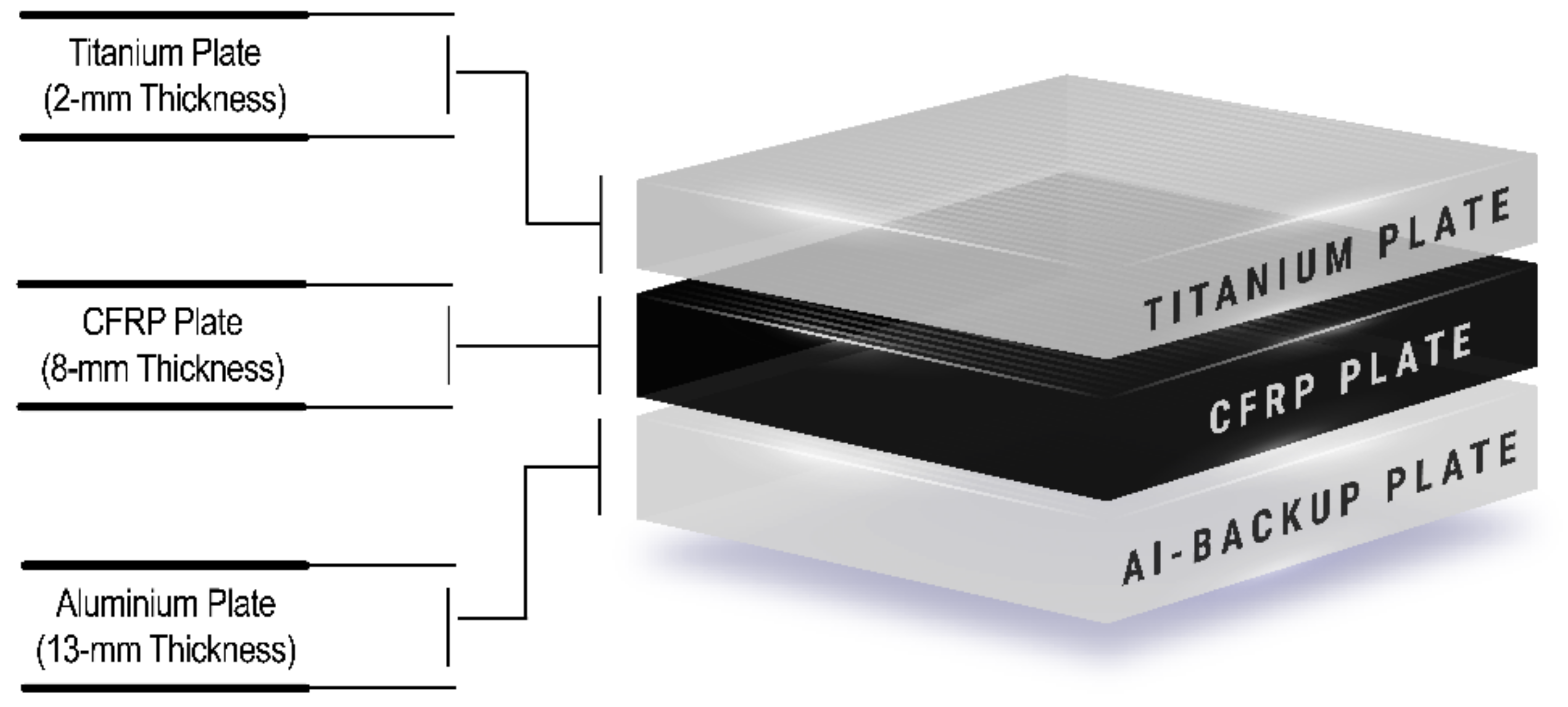
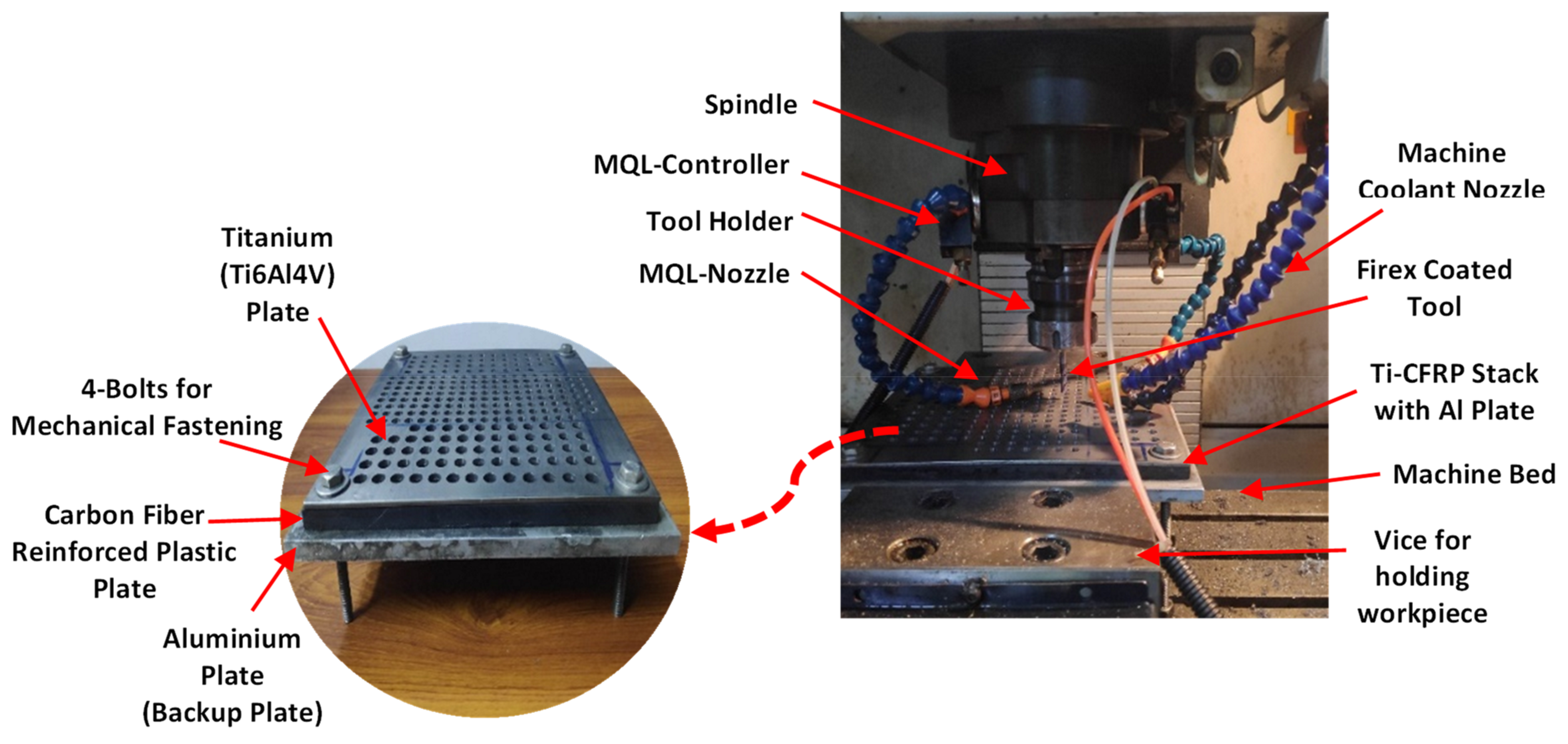
2.1. Machine Tool and Workpiece

The experimentation was carried out using 31-layered 3K carbon fiber of 200 g/m2 at 90° to each other. The layers were adhered with a bisphenol-based vinyl ester resin epoxy RF-1001 matrix to develop a 230 × 230 × 8 mm3 multi-directional quasi-isotropic (0°/90°/+45°/−45°) CFRP workpiece employing the hand lay-up technique. The properties of T300 carbon fiber, including tensile strength of 3530 MPa, density of 1.76 g/cm3, and plain weave fiber type for the experiments are listed in Table 2.
CFRP stacks were placed in the oven at 120 °C for about an hour for drying with a titanium plate on the top of the stack. The bottom side was supported using a backup plate of 13 mm in thickness made up of aluminum 2024. The backup plate was used with a rationale of its significant role in reducing tool wear by absorbing the heat at the exit of holes, reducing the vibrations produced, and eradicating the chattering of tools during the helical milling process. The schematic of the material for experimentation is shown in Figure 1. A 34 Nm standard torque on a micro-torque wrench was used for uniform balancing and fastening of the backup plate (see Figure 2). The uniformity in torque distribution was ensured at all points of fixture (where nuts and bolts had been tightened). Therefore, a standard procedure related to axle offset was followed before each experiment to minimize external variations. The experiment was carried out using an MCV-600 vertical milling machine (Long Chang Machinery Co. Ltd.). An isolated minimum quantity lubrication setup was used to assist machining process.
A Firex-coated end mill cutting tool was selected based on the manufacturers recommendation to process the composite having a Ti6Al4V sheet. The Firex-coated end mill was used with a 6 mm, 30° helix angle and four flutes and was manufactured by Guhring. The coating procedure was carried out at about 450 to 500 °C and different layers were introduced on the surface of tool. High-speed steel, carbide, and cermet were selected as the substrate material for the tools. The coatings possessed a red-violet color and had a thickness of 2–4 µm. The hardness of the coating was 3300 (HV 0.05), and the heat transfer rate was lower around 0.05 kW/mK. As per the manufacturer, the tools were suitable for the machining of almost hard-to-cut materials making them the universal tools in dry machining conditions and minimum-quantity lubrication techniques. Fernández-Valdivielso et al. [32] evaluated key features of carbide tools and supported the significance and performance of tools during turning of nickel-based alloys. From the trail experimentation, a 40 mm tool overhang was considered adequate to evade flattering and chattering of the tool during high-speed machining.

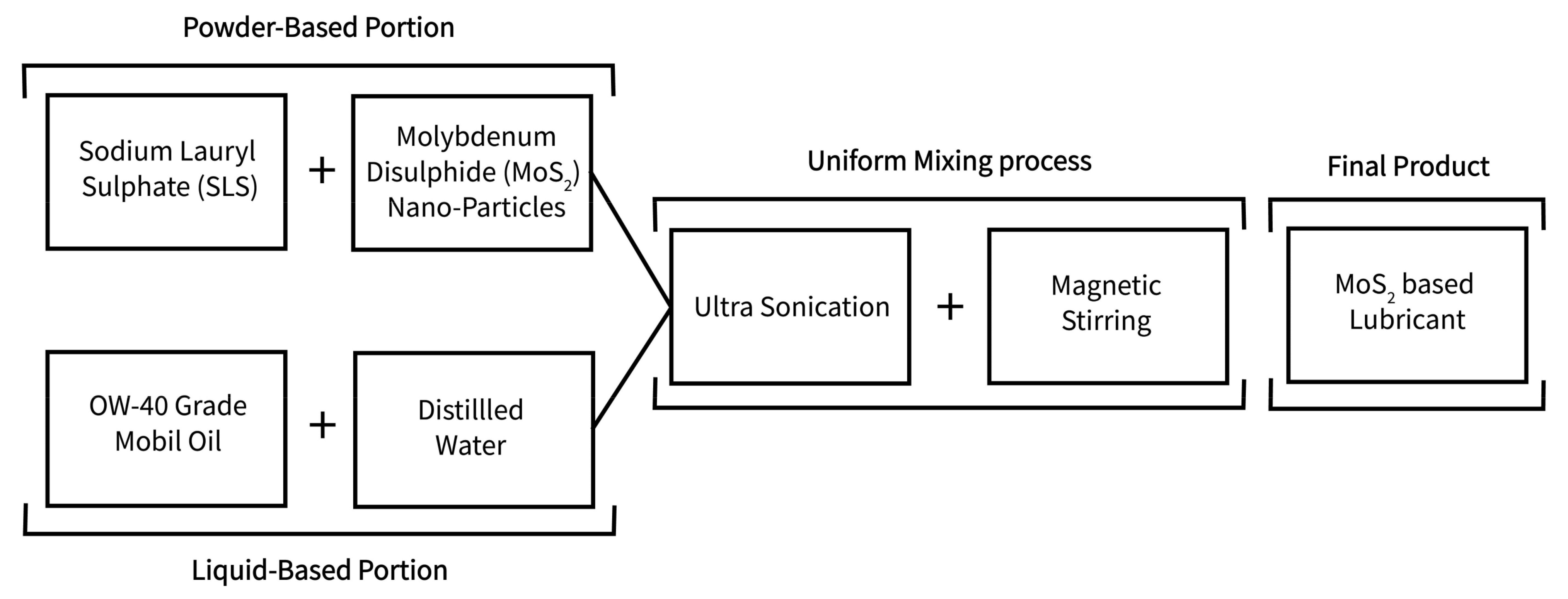
2.2. Experimental Design and Minimum Quality Lubrication Setup

To comprehensively evaluate tool wear during helical milling, a range of parameters were selected, including eccentricity, axial pitch, spindle speed, tangential feed, and lubrication. The parametric effects were examined using a design-of-experiments approach. Due to time and cost constraints, the Taguchi technique was selected because of its robust design and ability to characterize parametric trends. The parametric levels were predetermined based on the trail experimentation. The selection of specific range was carried out on the basis of substantial effect on tool wear without majorly compromising hole integrity. In total 36 experiments are carried out with the L18 Taguchi array. The Minitab statistical package 2022 version was used to develop the design of the experiment matrix. This software is widely used in manufacturing community for statistical analysis and ease of use which was also rationale behind choosing it for current study. The details are provided in Table 3.
Each experiment was divided into three steps to achieve complete machining of the CFRP/Ti6Al4V stack till aluminum backup plate. In the first step, the Ti6Al4V plate was machined, and the tool was bought back to the top zero position. In the second step, machining of CFRP portion ensured the complete drilled hole throughout the CFRP stack and the tool was retracted back to zero position. In the last step, the tool was bought to the maximum depth to verify the drilled depth. The experimental protocol was designed to reduce the tool wear and improve the hole quality by reducing the temperature. In addition, it was followed for tranquil removal of the burr during the retraction of the tool between the first and second steps. Another rationale behind this experimental protocol was appropriate lubrication mechanism. In trail experiments, it was established to machine the Ti6Al4V first followed by CFRP. This arrangement was done for sufficient lubrication of Ti4Al4V plate during the machining process. In the second step, the CFRP was machined dried with continuous high-pressurized air supply. The high-pressure air was introduced to reduce the abrasiveness by removing dust particles instantly resulting in improved hole quality. Introducing high-pressure air resulted a burr-free process with the least delamination and uncut fibers. However, the potential of minimum quantity lubrication was used for reduction of titanium burr high-quality machined holes.
Molybdenum disulfide (MoS2) is a solid lubricant commonly used in tribological applications due to its excellent lubricating properties. The key role of MoS2 in the wear mechanism is primarily to reduce friction between sliding surfaces, thereby reducing wear. When MoS2 is applied as a lubricant, it adheres to the metal surfaces and forms a thin film. This film acts as a physical barrier between the surfaces, preventing direct metal-to-metal contact and reducing friction [5,17]. The low friction coefficient of MoS2 allows sliding surfaces to move more easily, which reduces the amount of heat generated by friction and minimizes wear. In addition to reducing friction, MoS2 also has a unique layered crystal structure that allows it to act as a solid lubricant. The layers of MoS2 can slide over each other, providing a low-friction surface for sliding contact. This layering also allows the lubricant to withstand high pressures and shear forces, making it an effective lubricant in high-load applications. Overall, the key role of MoS2 in the wear mechanism is to reduce friction and wear by forming a protective film on the metal surfaces and providing a low-friction surface for sliding contact [17]. For machining of the composite, the MoS2-based minimum quantity lubrication system was used with 4 Bars pressure and 40 mL/h flow rate. The pressure and flow rates were optimized during trail experiments according to recommendations of Uysal et al. [38]. Both of the variables were carefully tailored considering the three steps of each experiment as introduced earlier. The schematic of experimental setup and workpiece details is shown in Figure 2. The preparation of nanofluid-based lubricant was carried out using 80% distilled water mixed with 19% of the fully synthetic OW-40 grade Mobil oil. The surfactant 5g odium lauryl sulphate was mixed with multiple compositions (0.5%, 0.75%, and 1%) of MoS2 acting as the solid lubricant in the experimentation campaign. The complete process of nanofluid-based lubricant-making is shown in Figure 3. The lubricant was agitated in an ultrasonic sonicator for 5 h at 20 khz @300 Watts. The lubricant was released for 24 h to shake using an analogue shaker. The suspended particles were then checked after 24 h to ensure proper mixing and then observed under microscope to determine the proper mixing of solid particles in distilled water and oil.

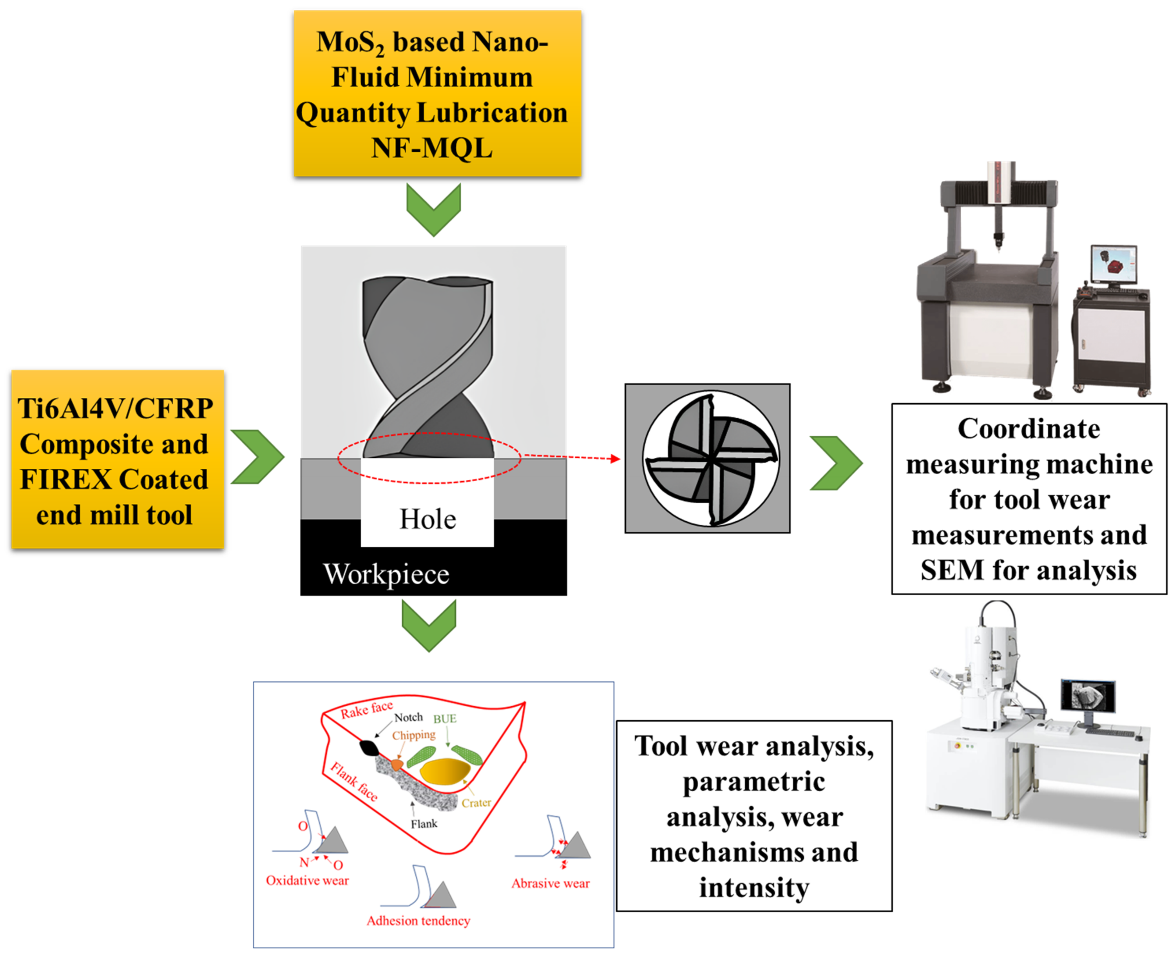
2.3. Tool Wear Measurement

The experimental roadmap to analyze the tool wear characteristics is shown in Figure 4. A Coordinate Measuring Machine (CE-450) by Chen Wei Precise Technology Co. was used to measure flank wear with the non-contact type options. The least count is 1 µm at 70× magnification. All measurements and calibrations were made with Quadra Check 500 (QC 500) supportable software. A reference plane was used with multiple measurements of the worn region. The line mode was used from the reference plane to measure the extreme wear points after each experiment. The tool and set-up, especially the fixture, were ensured to be unchanged and calibrated throughout the measurement process. The wear mechanism and intensity analyses were carried out using EDS-equipped Quanta 450 field emission gun (FEG) scanning electron microscopy.

3. Results and Discussion

3.1. Parametric Analysis

The parametric trends of process variables against tool wear are shown in Figure 5. The combined effects with two-way interactions can be observed, highlighting the significance of parametric levels. With the increase in spindle speed for CFRP from 6500 rpm to 7000 rpm (Figure 5c), the tool wear slightly decreased and the rise from 7000 rpm to 7500 rpm resulted in a significant increase. This is because the coated tool was significantly harder than the CFRP layer. Therefore, the prime focus was towards the Ti6Al4V layer, which induced major tool wear. In this regard, combined parametric effects were analyzed with CFRP spindle speed (Figure 5a–c) and Ti6Al4V spindle speed (Figure 5d–f). However, Figure 5c shows that the tool wear trend was different at different spindle speeds. For instance at 6500 rpm CFRP, the rise in Ti6Al4V spindle speed from 1000 rpm to 1250 rpm showed slight increase, whereas the rise from 1250 rpm to 1500 rpm significantly increased (by ~100%) tool wear. On the other hand, at high spindle speed (7500 rpm) the behavior was opposite for CFRP. Increasing the spindle speed from 1000 rpm to 1250 rpm increased tool wear from ~30 µm to ~95 µm, an increase of ~215%.
In Figure 5a, the increase in axial pitch from 1 mm to 2 mm resulted decreased tool wear from ~75 µm to ~67.5 µm. The decrease (10%) in wear was not intense, as the µm range was fairly small considering the least count of the measuring device. The tool wear was significantly decreased from 1 mm to 1.5 mm axial pitch. From 1.5 mm to 2 mm, tool wear increased in a linear fashion. The effect was in line with findings of Puerta-Morales et al. [39] during helical milling of titanium alloy UNS R56400. However, the tangential feed (see Figure 5b) affected tool wear significantly. At low tangential feed of 0.01 mm/tooth, the tool wear was around ~47 µm which increased to ~85 µm at 0.03 mm/tooth, showing ~80% increase.
The lubrication, which carried a percentage of the nanoparticles in the fluid, was affected differently compared to axial pitch and tangential feed. However, the influence of machining parameters (see Figure 5c) on the CFRP layer was not sufficiently sharp in terms of tool wear. The increase in the MoS2 concentration from 0.5% to 1% in the lubricant reduced tool wear from ~85 µm to ~75 µm. This improvement was because of the tribological characteristics of the nanoparticles in the cutting zone. The NF-MQL system produced a mist in the machining zone where a stable thin layer was introduced between the tool and workpiece, as shown in Figure 6. When the water-mixed nanofluid was introduced, the evaporation of the water took place rapidly, leaving a film of base oil and nanoparticles. Haq et al. [40] also found similar scientific process with a Cu-nanoparticle-based MQL system. The thin tribo-film enhanced tool/workpiece frictional properties by providing excellent lubricity. This mechanism resulted in dissipation of the shearing heat from the machining zone, which improved tool wear characteristics.
Lubrication thus improved tool wear with an enhancement of tribological conditions. A similar behavior is observed in Figure 5f. However, the effect of spindle speed was significantly higher than that of lubrication. With the increase in spindle speed from 1000 rpm to 1500 rpm, tool wear increased from ~50 µm to ~75 µm, showing 50% rise. It is clear that the increase the spindle speed during machining of the Ti6Al4V layer led to high tool wear whereas the increased percentage of MoS2 helped to reduce the tool wear. High speed resulted in temperature rise in machining zone which affected it severely because of thermal resistance of the alloy. This observed scientific process is in line with Ge et al. [7]. Therefore, a high concentration of MoS2 in the lubricant and low spindle speed introduce a balanced cooling mechanism, reducing the heating effect and associated wear. For Ti6Al4V, the increase the spindle speed and axial pitch resulted in significantly higher tool wear characteristics because the difficult-to-cut nature of alloy (see Figure 5d). The combined increase of spindle speed and axial pitch introduced large cutting forces because of the removal of unit material in relatively shorter time. Therefore, low speed and axial pitch are recommended to lower tool wear. In Figure 5e, a similar behavior of tangential feed is observed as axial pitch. The rise rate in tool wear at 0.01 mm/tooth to 0.03 mm/tooth was higher at 1000 rpm spindle speed as compared to spindle speed 1500 rpm. The highest tool wear was observed at high spindle speed of 1500 rpm and high tangential feed of 0.03 mm/tooth. The physical science of the tangential feed is similar to axial pitch where cutting forces are significantly affected. It is clear that the wear was significantly affected by parametric conditions. The spindle speed had significant effect on tool wear during machining of Ti6Al4V as compared to the CFRP layer. Low levels of tangential feed, axial pitch, and spindle speed and high levels of lubrication produced favorable conditions for efficient machining.
The effect of eccentricity is shown in Figure 7a. With the increase in eccentricity from 1 mm to 2 mm, a minimal linear increase in tool wear was observed. The rise in tool wear was from ~62 µm to ~64 µm. A similar behavior of tool wear was observed in the case of spindle speed parametric conditions specified against Ti6Al4V. At 1500 rpm and 2 mm eccentricity, the tool wear was around ~94 µm as compared to ~46 µm at 1000 rpm and 1 mm eccentricity. The interactive effect of eccentricity with axial pitch is shown in Figure 7b. The change in eccentricity did not show significant variation in tool wear. With the increase in axial pitch from 1 mm to 2 mm, tool wear increased from ~47 µm to ~70 µm. The maximum tool wear was observed at 2 mm axial pitch and 1 mm eccentricity. The increase in axial pitch worsened the cutting forces which contribute to abrasive wear. Therefore, low axial pitch and eccentricity values are recommended to reduce tool wear. The joint effect of eccentricity with spindle speed to machine the Ti6Al4V layer in the composite is shown in Figure 7c. The increase in spindle speed for Ti6Al4V from 1000 rpm to 1500 rpm and eccentricity level from 1 mm to 2 mm showed a significant linear rise in the tool wear (see Figure 7c). High spindle speed with extreme eccentricity resulted in significantly higher wear. However, the trend in tool wear was the same for spindle speed at low and high levels of eccentricity. A similar behavior was observed in the case of eccentricity and tangential feed (see Figure 7d). In this case the high wear was observed at 0.03 mm/tooth and 1 mm eccentricity. However, the lubrication and eccentricity interactive effect was opposite when compared to other variables with eccentricity. At low nanofluid concentrations, the eccentricity resulted in significantly higher wear at all levels. However, with the increase in nanofluids to 1%, the tool wear was significantly reduced from ~75 µm to ~50 µm resulting ~33% decrease at 2 mm eccentricity.
The parametric trend of axial pitch with tangential feed is shown in Figure 8a. The increase of the axial pitch from 1 to 2 mm resulted in a slight increase in tool wear. However, the tangential feed influenced the tool wear severely as compared to axial pitch. The increase in tangential feed from 0.01 mm/tooth to 0.03 mm/tooth resulted in tool wear rise from ~50 µm to ~85 µm and showed a 70% increase at 1 mm axial pitch. The increase in tool wear also showed a similar trend at 2 mm axial pitch, starting from a slightly higher position at 0.01 mm/tooth. The maximum tool wear was observed at the 1 mm axial pitch and 0.03 mm/tooth tangential feed because of their combined effect in increasing shear forces. At low tangential feed and axial pitch, the tool wear was around ~47 µm. The axial pitch and lubrication show a similar trend to that of tangential feed and lubrication in terms of tool wear (see Figure 8b,c). However, the low level of axial pitch and lubrication resulted in tool wear in the range of ~46 µm, whereas the low levels of tangential feed and lubrication resulted tool wear around ~59 µm. An increase in the amount of MoS2 in the lubricant for the MQL setup resulted in wear reduction at low levels of axial pitch and tangential feed. Therefore, high levels of nanofluids with low levels of other variables are recommended to reduce tool wear conditions.

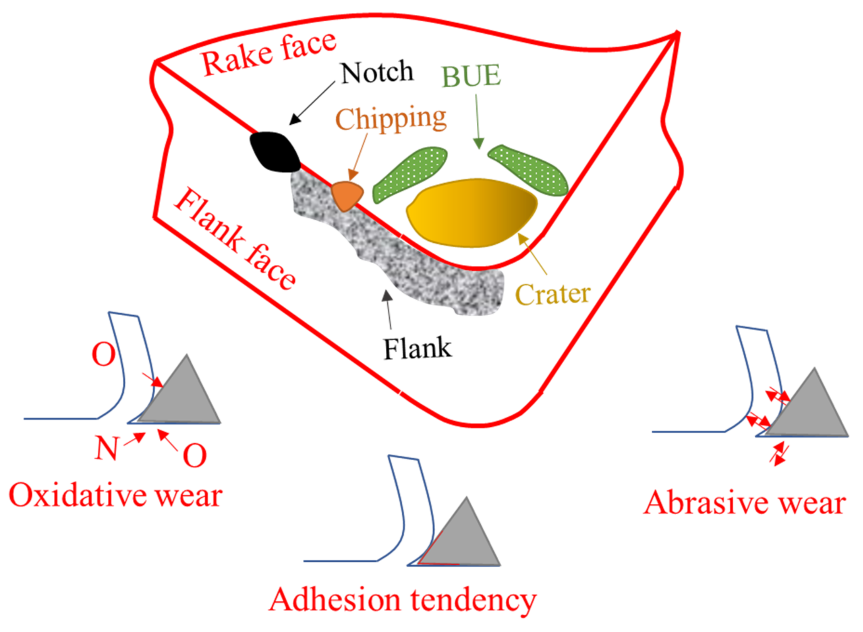
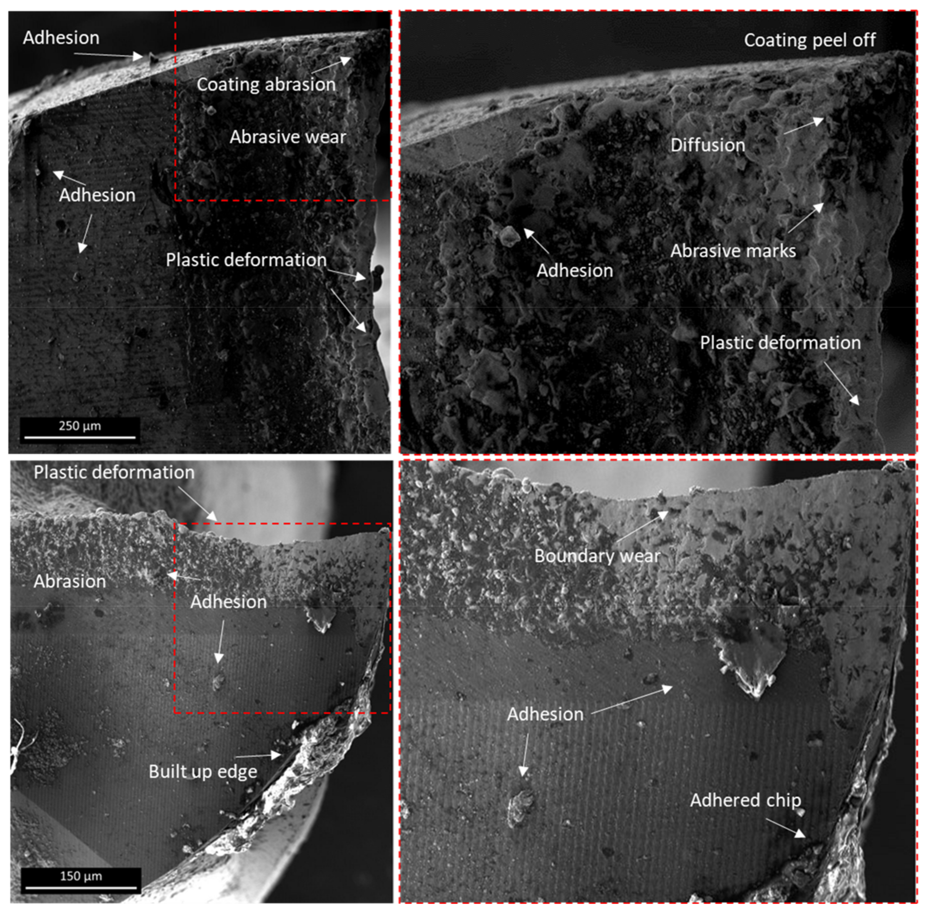
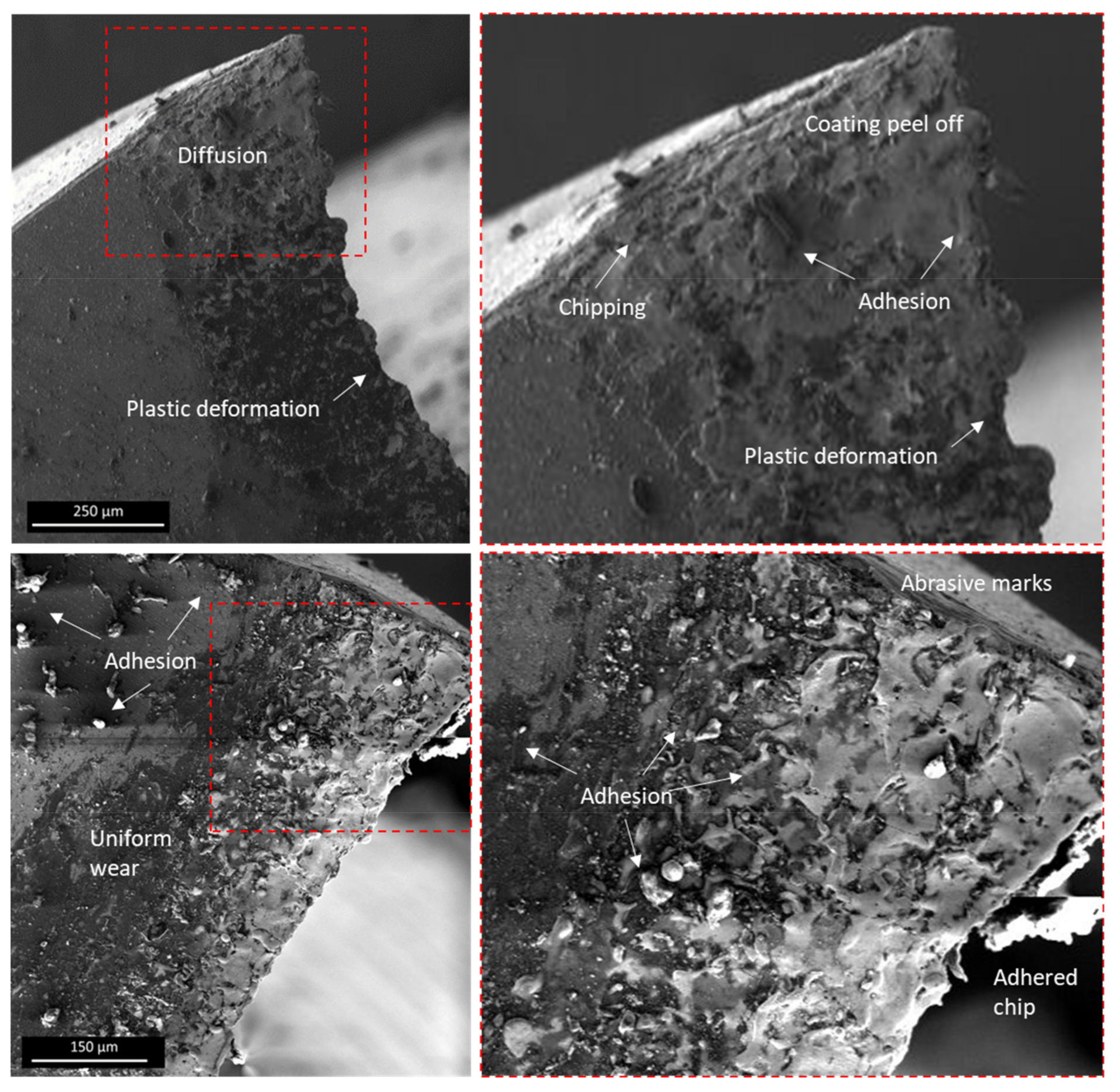
3.2. Tool Wear Mechanisms

Helical milling is considered an advanced hole-developing technique in the aviation industry. In the process, the tool moves along the helical path with constant axial feed in the workpiece resulting in complex wear mechanisms, as compared with other manufacturing processes. In this study, the wear limit for helical milling was considered to be ten holes per tool. The resulting wear mechanisms including abrasion, chipping, and adhesion, which significantly reduce the tool life, were analyzed. Wear is generated because of the temperature of the cutting zone resulting from friction between the tool and workpiece. The cutting speed, material properties of tool/workpiece, and the lubrication mechanisms also affect the tool wear characteristics, as evidenced from parametric analysis. The detrition of tool material also happens due to continuous operations in several patterns. The observed tool wear modes during the helical milling of CFRP/Ti6Al4V under a MoS2-based NF-MQL system showed evidence of chipping and fracture, while the promoting mechanisms were abrasion, attrition/adhesion, built-up edge, diffusion, plastic deformation, and oxidative wear. Liew [41] investigated tool wear modes during the low-speed milling of STAVAX-modified 420 stainless steel with a TiAlN single-layer and TiAlN/AlCrN nano-multilayer-coated carbide inserts using different lubrication conditions (spray-based and flooding). The significant wear-promoting mechanisms were abrasive, delamination, and attrition. These mechanisms resulted in individual surface cracks and fractures of the carbide substrate. The authors showed that low cutting speed resulted in greater protection of the coating. In addition, the slow pace resulted in high resistance against delamination and abrasion wear because of delayed cracking and fracture. The tool wear and its promoting mechanisms are shown in Figure 9. Oxidative wear, which is results from the reaction of oxygen at the tool/workpiece interaction zone at high temperatures, contributes to deteriorating tool life. The adhesion tendency results from the high temperature affinity of workpiece surface or chips, causing them to adhere to the tool surface. This mechanism causes a built up edge, and sometimes pressure-welding of chips results in removal of tool material in the form of chipping. The abrasive wear is the common mechanism observed when two bodies are brought in relative contact of each other with force. This mechanism results in flank wear and cracking. Based on the material properties, the intensity of abrasive wear can also result in complete failure of the tool. The other types of wear such as crater, notch wear, and chipping are shown in Figure 9. Qin et al. [42] carried out milling of Ti6Al4V under MQL conditions and found micro-chipping, thermal cracking, uniform flank wear, and flaking as major tool wear types. The leading promoting mechanisms were attrition, adhesion, and diffusion under all the cooling-lubricant settings on the cemented carbide tool. The authors recommended that the MQL system could potentially improve tool/workpiece tribological characteristics and control wear mechanisms by several fold as compared to dry conditions.
The analysis of tool wear mechanisms was carried out in two experimental conditions resulting in the maximum tool wear of 106 µm and minimum tool wear of 13 µm. Extreme tool wear was observed at eccentricity level 2, spindle speed for Ti6Al4V of 1500 rpm, spindle speed for CFRP of 6500 rpm, the axial pitch of 1.5 mm, tangential feed of 0.02 mm/tooth, and 0.5% MoS2 nanoparticles. In contrast, the low tool wear observed was at eccentricity level 1, spindle speed for Ti6Al4V of 1000 rpm, spindle speed for CFRP of 7500 rpm, tangential feed of 0.01 mm/tooth, the axial pitch of 1.5 mm, and 1% of MoS2 nanoparticles. Scanning electron microscopic analysis was carried out to highlight wear modes and their associated mechanisms. In both of the cases, abrasive wear was one of the major contributors to the overall tool wear. In Figure 10, low wear conditions are presented where evidence of abrasive wear, adhesion of different particles, built-up edge, and boundary wear are available. The fundamental reason for abrasive wear was the frictional effect developed between tool and workpiece materials. The high hardness of the material (tool/workpiece) introduced cutting forces and severely impacted tool wear by increasing the friction and heat in the interaction zone. Low wear was associated with low spindle speed during machining of Ti6Al4V and high nano-particles in lubricant. The nanoparticles in the lubricant introduce tribological characteristics and aid in the material-removal process.
The comparison of two-body abrasion and three-body abrasion is shown in Figure 11. In two-body abrasion, the surface of cutting tool and workpiece is directly in contact, resulting in increased possibility of adhesive wear and extreme abrasive wear. However, in the case of three-body abrasion, the nanoparticles and carbide particles aid in machining action by inducing additional support in material-removal of the workpiece. In addition to the abrasive properties of the particles, the NF-MQL system introduces a mist of nanoparticles in the tool/workpiece interaction zone. These particles introduce a rolling effect on the surface by reducing surface roughness of workpiece, as shown in Figure 11. Similarly, the nanoparticles introduce a tribo-film on the surface which protect surfaces from damage and catastrophic failures. In addition, the mending effect improves the surface properties of the surface. Haq et al. [40] showed significant improvements in work roughness and tool wear by employing Cu a nanoparticle-based NF-MQL system. Lastly, the nanoparticles introduce polishing effects on the surface. These properties not only improve work-surface integrity but also improve tool life by improving tribological properties and balanced cutting force distribution.
The abrasion marks are evident in Figure 10. However, the experimental conditions did not result in significant wear volume. Li et al. [43] showed similar mechanistic findings during helical milling of Ti6Al4V. The authors observed craters and fractures at the cutting edge because of cutting-force vibrations. Severe damage was observed at the tool nose which mainly originated from adhesion and diffusion phenomena. The evidence presented in Figure 10 shows that this could potentially lead to catastrophic failure risk because of the adhesion and diffusion mechanisms. However, because of low spindle speeds, the damage could potentially be delayed in comparison to high spindle speed.
The highest tool wear (see Figure 12) was observed at spindle speed 1500 rpm to machine the Ti6Al4V layer, and with 0.5% nanoparticle concentration in the lubricant. The high spindle speed caused severe thermal damage, as evident in the micrographs. The excessive diffusion on the nose, plastic deformation, and chipping potentially increased the risk of catastrophic failure. The SEM comparison of both experimental conditions show different wear modes at changing intensities of wear because of the working conditions. The adhesion and diffusion at the tool nose were major wear mechanisms found in both cases whereas oxidation and diffusion were detected at the periphery cutting edge. The high working conditions with low nanoparticles in lubricant resulted in high temperature and thrust forces which resulted in severe abrasion marks.
As shown in Figure 13, the increase in speed resulted in reduced coating delamination, chipping, and mechanical fatigue. A similar mechanism is evident in Figure 10 and Figure 12. The fracture is clearly visible between the peripheral and frontal edges. The reason for the chipping in this particular region is associated with the excessive stress along the peripheral face and the cutting speed being localized along the frontal edge. In this region, the local temperature was significantly increased with the start of the thermal cycle. Therefore, the chipping was seen at low nanoparticle concentration because of poor temperature-balancing. However, the adhesion was significantly increased with the increased area of diffusion. With the improvement in spindle speed, the mechanical damage reduced with the reduction in nanoparticles having a significant influence. Increasing the percentage of MoS2 caused a positive impact on tool life and reduced tool wear. Therefore, optimized process settings are important in reducing tool wear. Wang et al. [44] compared helical milling of CFRP/Ti6Al4V with individual layers. In the individual layer of Ti6Al4V, major wear mechanisms were crater, chipping, and adhesion, whereas for the individual layer of CFRP, the dominant wear mechanisms were abrasion and edge chipping. For CFRP/Ti6Al4V, the authors showed abrasion as the prominent tool wear mechanism due to the composite material and catastrophic failure/breakage because of Ti6Al4V.
The comparison of the tool nose at the highest and lowest wear is shown in Figure 14. The rainbow-color-overlay-processed images show clear differences in the change in tool conditions based on SEM images. The built-up edge and adhesion are evident for experimental conditions producing low flank wear (see Figure 14a). Helical milling at high speed reduced mechanical damage but increased thermal damage and plastic deformation resulting from large friction at the workpiece/tool interface. The high cutting forces/pressure and temperature developed between the rake face and chips increased adhesion tendency resulting in a welding scenario of chips to the tool. The clinging of chips at the cutting periphery of the tool is shown in Figure 14. Ge et al. [7] showed the comparison of dry helical milling with an MQL-based process. The authors found that significant adhesion and chipping were observed in dry conditions. The MQL improved the tool wear characteristics and resulted in a low degree of adhesion. Wang et al. [45] studied the wear and breakage of TiAlN- and TiSiN-coated carbide tools. The cutting speed significantly affected wear mechanisms. The flank wear, rake face wear, chipping, and coating peeling were major tool wear phenomenon based on abrasive and adhesive wear. Figure 14b shows plastic deformation resulting in tool fracture. The reduced nanoparticles in the NF-MQL and other process variables increased cutting forces which ultimately resulted in failure.
The chemical analysis of tool wear produced at MoS2 1% is shown in Figure 15. Evidence of W (tungsten) and Fe (iron) was found at the tool edge which was directly in contact with the workpiece. Spots 2 and 3 showed evidence of oxides and carbides. The evidence of chips adhering can also be seen in the micrograph. Spot 4 showed the original FIREX coating. N, Al, Ti, and C are elements that were present in the original coating. Near the tool nose, the elements W and Co were introduced as a result of adhesion tendency and abrasion, whereas the cutting edge showed evidence of C, O, Fe, and Co with reduced content of Al and Ti. Evidence of Mo was also present on the cutting edge showing the formation of tribo-film of 1% nano particles.
The EDS spots in Figure 16 mainly show that coating was still intact with the tool and the produced wear was not severe. However, the EDS spots near the cutting surface show evidence of elements from the workpiece material and show slight influence of wear. Ge et al. [7] showed evidence of workpiece material transfer and chip adhesion under an MQL-based system. Similarly, Wang et al. [44] highlighted the disappearance of N element from the original coating. The authors discussed that strong affinity during the machining cycle had resulted in this disappearance. Similar behavior also occurred during machining with 1% nanoparticles (Figure 15).
The evidence of diffusion and adhesion are shown in a micrograph of extreme wear conditions (Figure 16). The EDS at spot 3 shows the original coating elements such as N, Ti, C, and Al. Similar behavior of elements was observed at high spindle speed as compared to low spindle speed. However, because of low nanoparticle concentration, the Mo elements were reduced on the surface, which supported the low formation of tribo-film as compared to 1% nanoparticles. The potential formation of TiOx on the surface and the attraction between tool and workpiece material under high pressure was expected because of increased content of oxygen near the cutting edge as compared to original coating. The EDS at spot 1 shows elements such as W, Co, and C, highlighting significant material transfer from the workpiece to the tool. Similarly, the EDS at spot 2 shows C, O, Na, Co, Ta, and Mo. The near-cutting-edge element transfer was the result of chemical reactions at elevated temperature. The presence of oxygen shows the occurrence of oxidative wear which negatively influences tool lifecycle and peels off the coating.

3.3. Extended Study

The tool behavior in long-term tests was studied during the helical milling of CFRP/Ti6Al4V. The trend mapping was carried out during the machining of 200 holes, and the related wear was measured at optimized machining parameters (see Figure 17). In the complete extended study, tool wear could be categorized into three major regions. Firstly, the rapid tool wear, which takes place at the initial stages of machining, and includes the removal of coating material. Secondly, the steady wear region in which the tool wear is moderate. Lastly, the accelerated wear region in which a sudden rise in tool wear occurs after which the tool moves towards a fracture state (chipping and plastic deformation). The SEM analysis of the worn tool (see Figure 18) shows that the dominant modes of wear mechanisms were adhesion and abrasion. The abrasion mechanism, as shown in Figure 17, was gradual tool wear which was produced with two- or three-body abrasion during machining. The episodes of tool wear of the tool at different stages of the experimentation were mapped and correlated with micrographs. In the bar graph, rapid tool wear was observed from the start until 50 holes. Figure 17a shows the tool conditions after 100 holes, where the tool edge had started rounding. In Figure 17b, the edge started rounding after 130 holes. The tool surface started deteriorating with the propagation of micro-cracks on the tool face. The cracking led to fracture-initiation after 180 holes, as shown in Figure 17c. A similar phenomenon, which led to the complete fracture of the tool, is evident in Figure 17d. After 160 to 200 holes, accelerated wear was seen, resulting in a worn tool, as shown in Figure 17e.
The chemical and surface analysis of the worn tool is shown in Figure 18 to identify the failure mechanisms after 200 holes. The major tool wear mechanism observed was material adhesion due to the bond developed between the Ti6Al4V elements and the tool coating material. The adhesion wear is shown in Figure 18b and was majorly derived from Ti6Al4V chemical affinity with the tool coating and the high cutting forces. A similar mechanism was found by Gutzeit et al. [46]. At high pressures, the formation of TiOx precursors resulted in the facilitation of mechanical adhesion which limited the performance, as shown in the mechanistic trend plot in Figure 9 and Figure 13. The chemical analysis showed diffusion of C at a high rate as compared to metal elements such as W and Co. Li et al. [47] carried out MQL-based milling of additively manufactured Ti6Al4V and found similar tool wear mechanisms during the hole-making process. The authors described the diffusion of elements as one of the major reasons for tool fragility.
Abrasion was another commonly found tool wear mechanism in the current study. This resulted from long tool engagement and lead to tool fracture. The abrasive wear significantly removed the coating at the cutting edge and severe plastic deformation was evident. The cutting edge had abrasive marks and wear because of the friction between the tool and the workpiece material. Furthermore, chipping was also observed at the cutting edge of the tool, as shown in Figure 18a. The chipping mechanism was significantly increased between peripheral and frontal edges. The appearance of fractures in this region was associated with local cutting speed and stress at the frontal and peripheral edges, respectively. A similar scientific process was described by Fernández-Vidal et al. [48] during the dry helical milling process.

3.4. Chip Morphology

It is important to compare chip morphology in order to identify the material removal characteristics. The chips of Ti6Al4V are susceptible to being curved and bend at an angle and become tangled around the holder flutes of the tool. These tangled chips create problems in the smooth ejection of the chip. Chips formed during hole-making in Ti6Al4V possess different properties than the material because of the heat generation during the cutting process. Xu and El Mansori [3] classified chips as built-up edge, continuous, and discontinuous. Because of the adhesive tendency of Ti6Al4V, the tool develops resistance and jamming because of chip adhesion. The chip morphological analysis is carried out at different experimental conditions, as shown in Figure 19. At a high axial pitch of 2 mm and 1250 rpm speed, straight ribbon-like chips were formed, as shown in Figure 19a. In comparison to Figure 19a, Figure 19c shows that a high nanoparticle concentration of 1% resulted in discontinuous chip formation, whereas high spindle speed also reduced the chip length and increased chip breakability.

4. Conclusions

The study evaluated the potential improvement in tool wear characteristics using MoS2-based NF-MQL during helical milling of CFRP/Ti6Al4V. A wide range of input variables such as eccentricity, spindle speeds (individual for CFRP and Ti6Al4V), axial pitch, and tangential feed on tool wear, were considered. A systematic experimental campaign was carried out followed by electron microscopic analyses to correlate tool wear mechanisms with material and parametric effects. This process-based and mechanistic analysis led to the following conclusions.
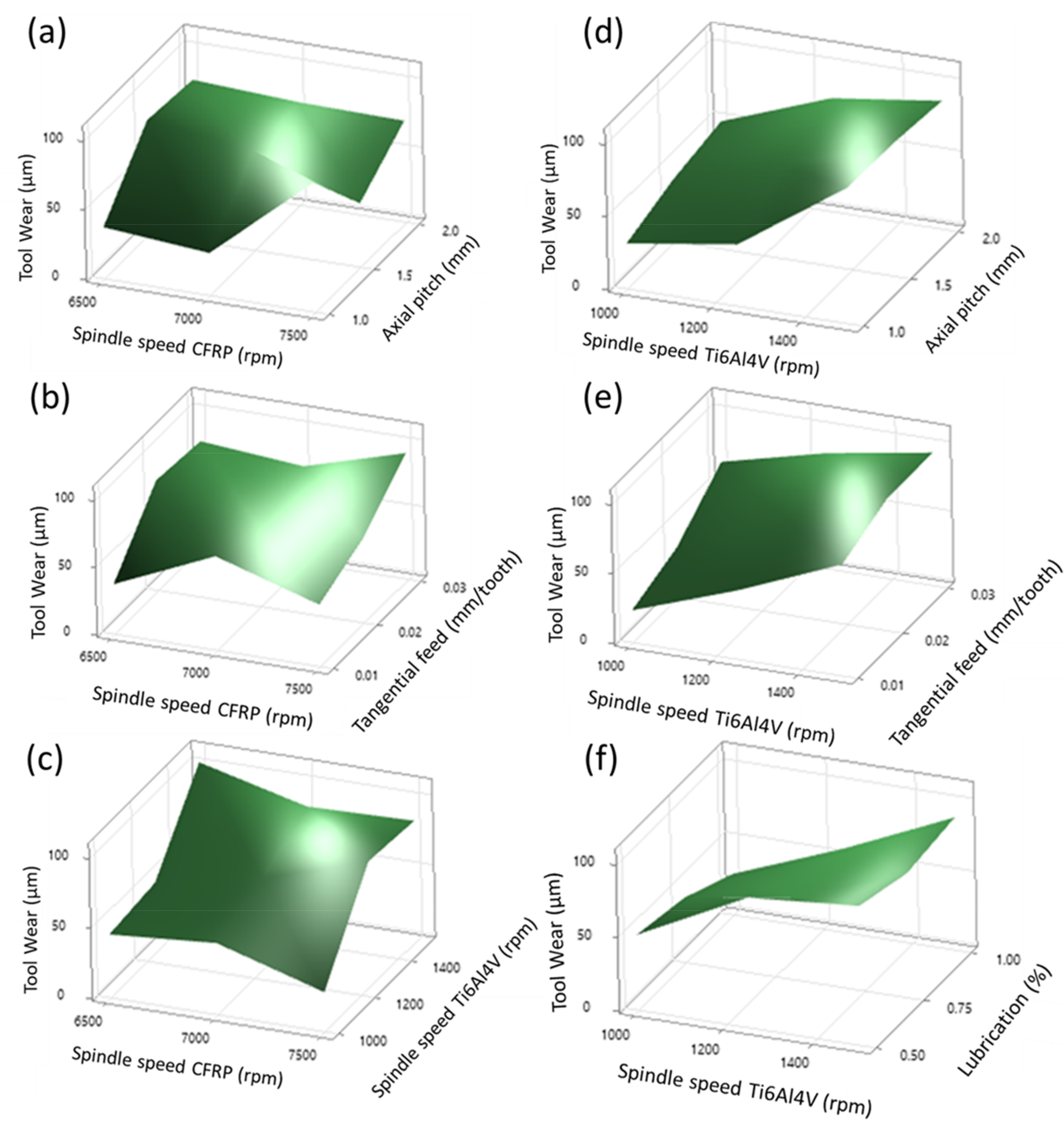
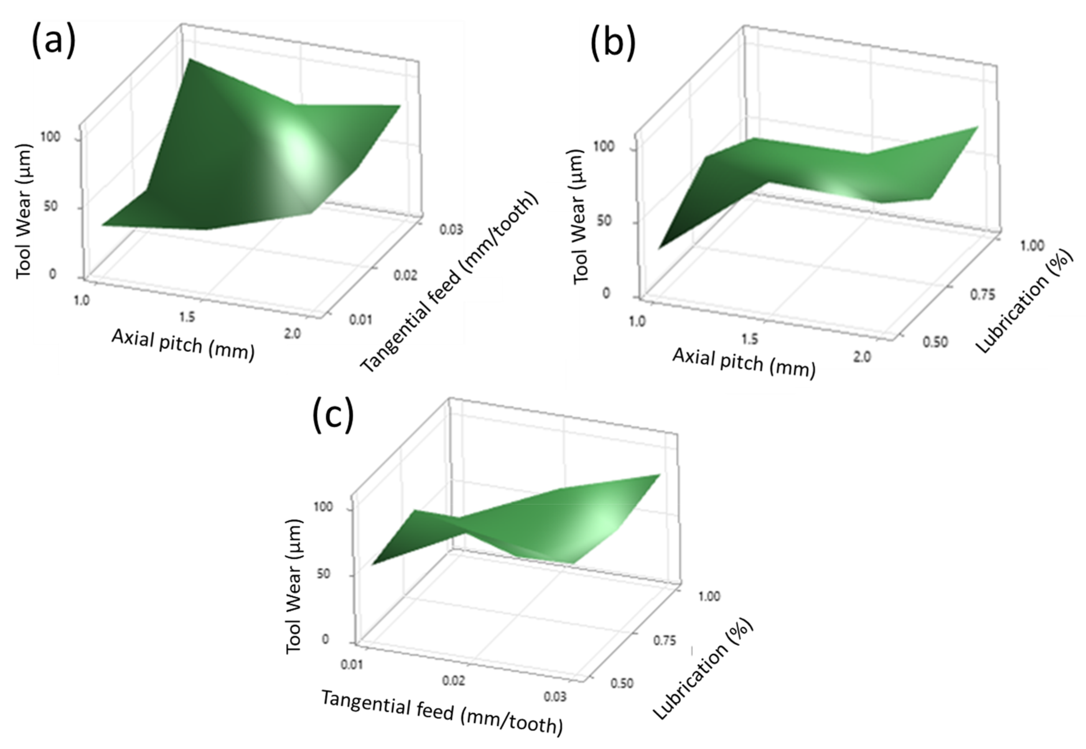
  • A low level of axial pitch and lubrication resulted in tool wear in the range of ~46 µm, whereas low levels of tangential feed and lubrication resulted in tool wear around ~59 µm. An increase in the amount of MoS2 in the lubricant for the MQL setup resulted in wear reduction at low levels of axial pitch and tangential feed. Therefore, high levels of nanofluids with low levels of other variables are recommended to reduce tool wear conditions.
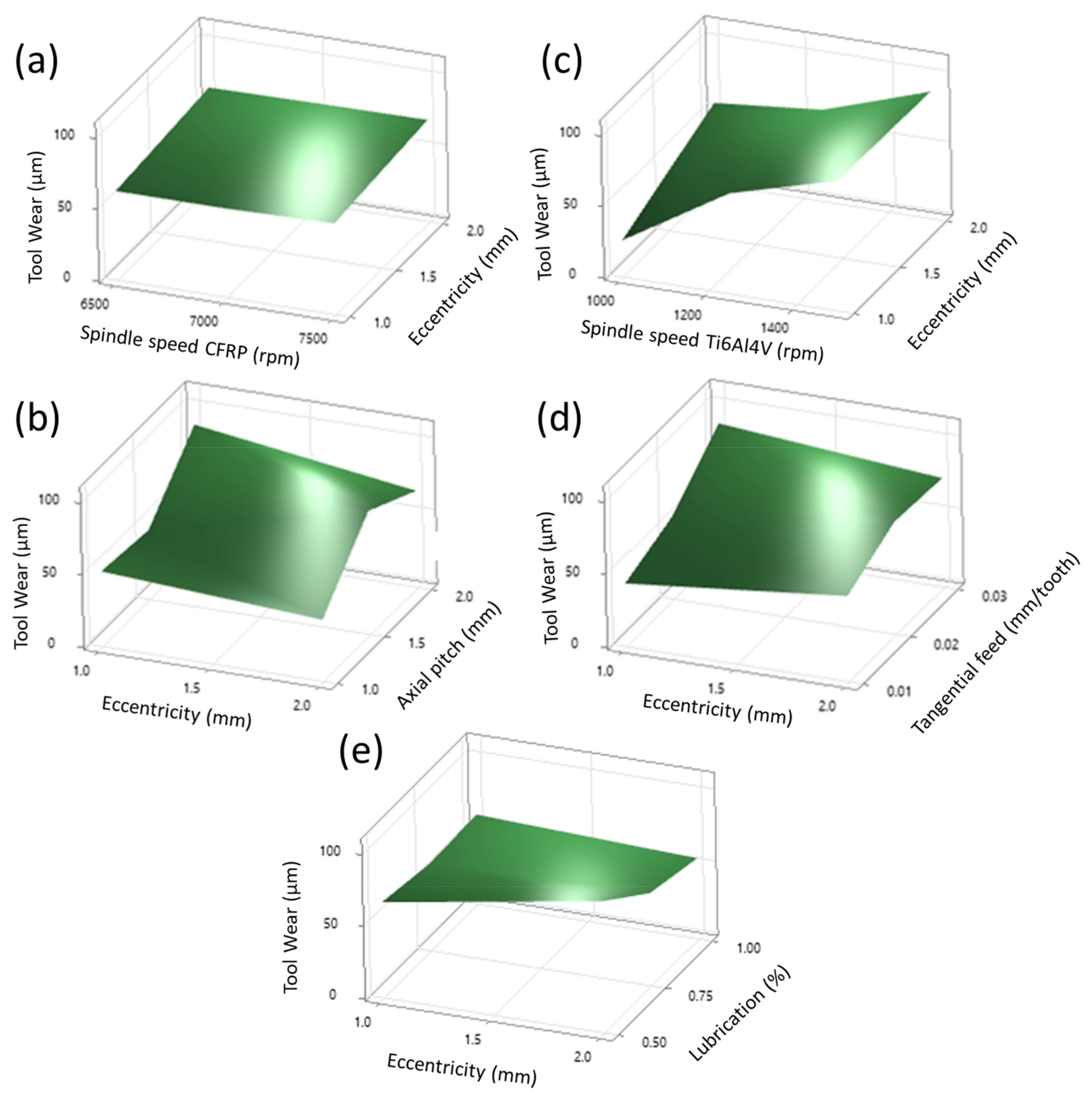
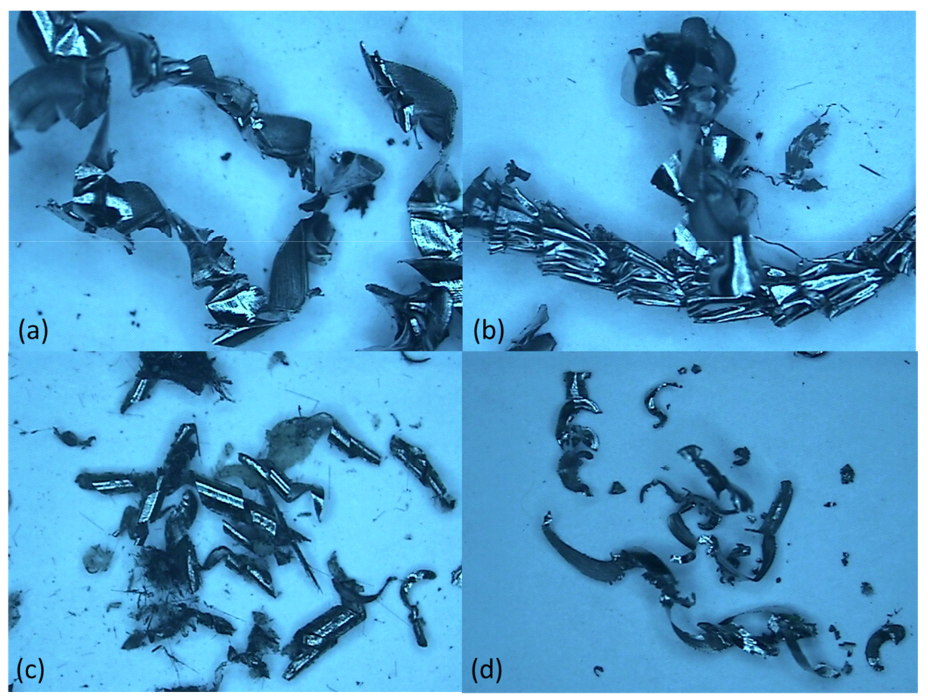
  • The analysis of tool wear showed extreme tool wear (106 µm) at eccentricity level 2, spindle speed for Ti6Al4V of 1500 rpm, spindle speed for CFRP of 6500 rpm, axial pitch of 1.5 mm, tangential feed of 0.02 mm/tooth, and 0.5% MoS2 nanoparticles, whereas low tool wear (13 µm) was observed at eccentricity level 1, spindle speed for Ti6Al4V of 1000 rpm, spindle speed for CFRP of 7500 rpm, tangential feed of 0.01 mm/tooth, the axial pitch of 1.5 mm, and 1% of MoS2 nanoparticles. The high nanoparticles concentration of 1% resulted in discontinuous chip formation.
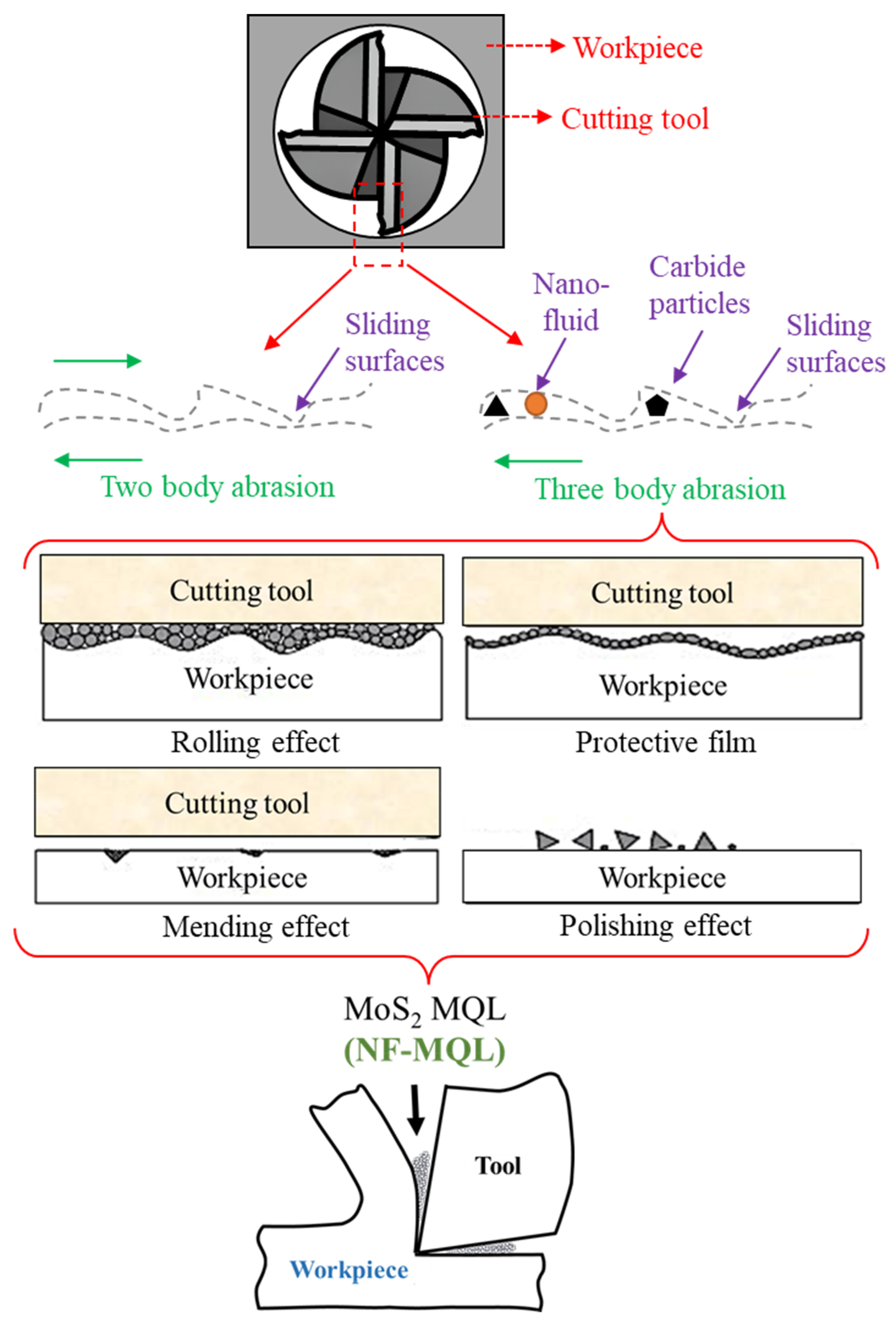
  • Lubrication which carried a percentage of nanoparticles in the fluid had different effects as compared to axial pitch and tangential feed. The increase in the MoS2 concentration from 0.5% to 1% in the lubricant reduced tool wear from ~85 µm to ~75 µm. This improvement was because of the tribological characteristics of the nanoparticles in the cutting zone.
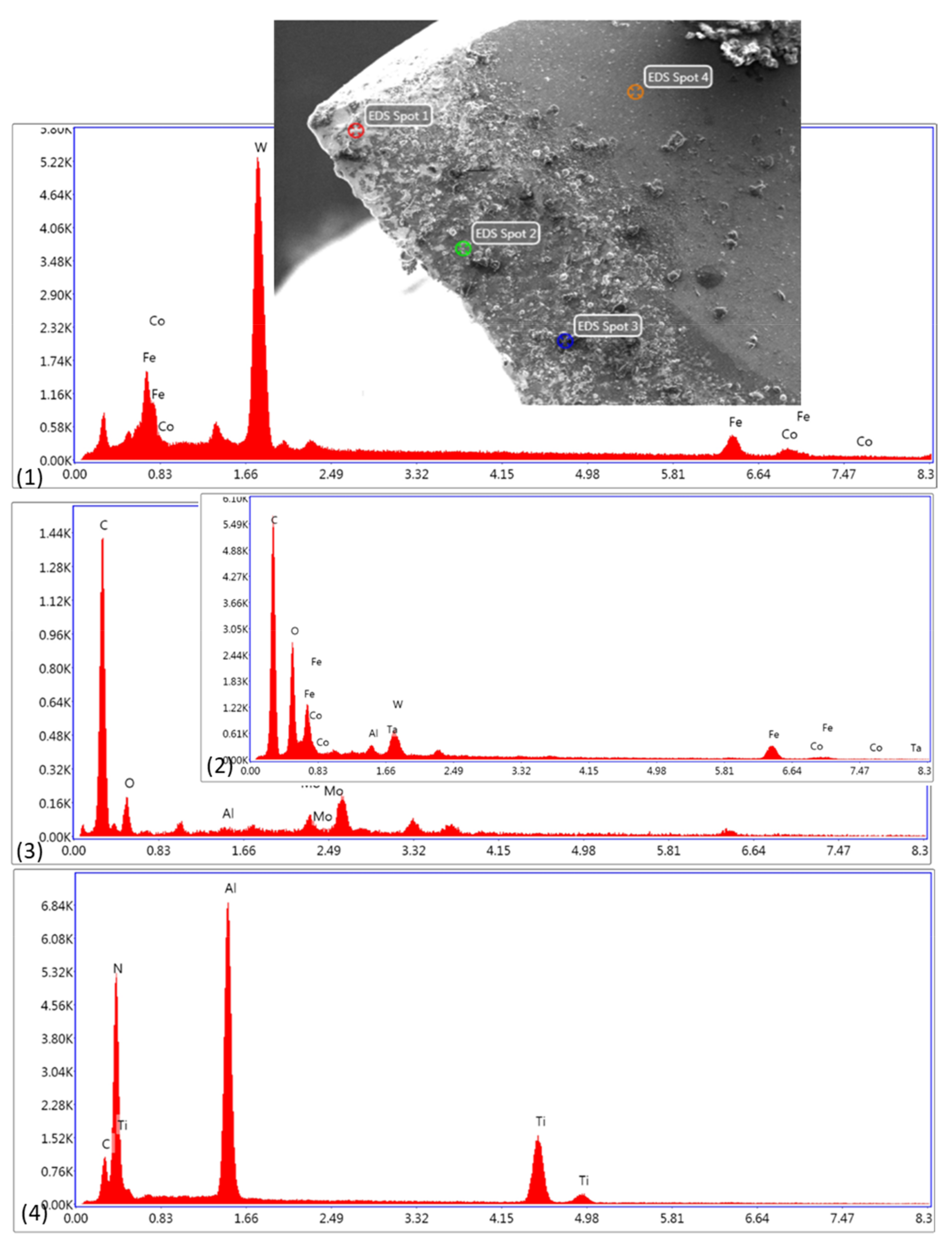
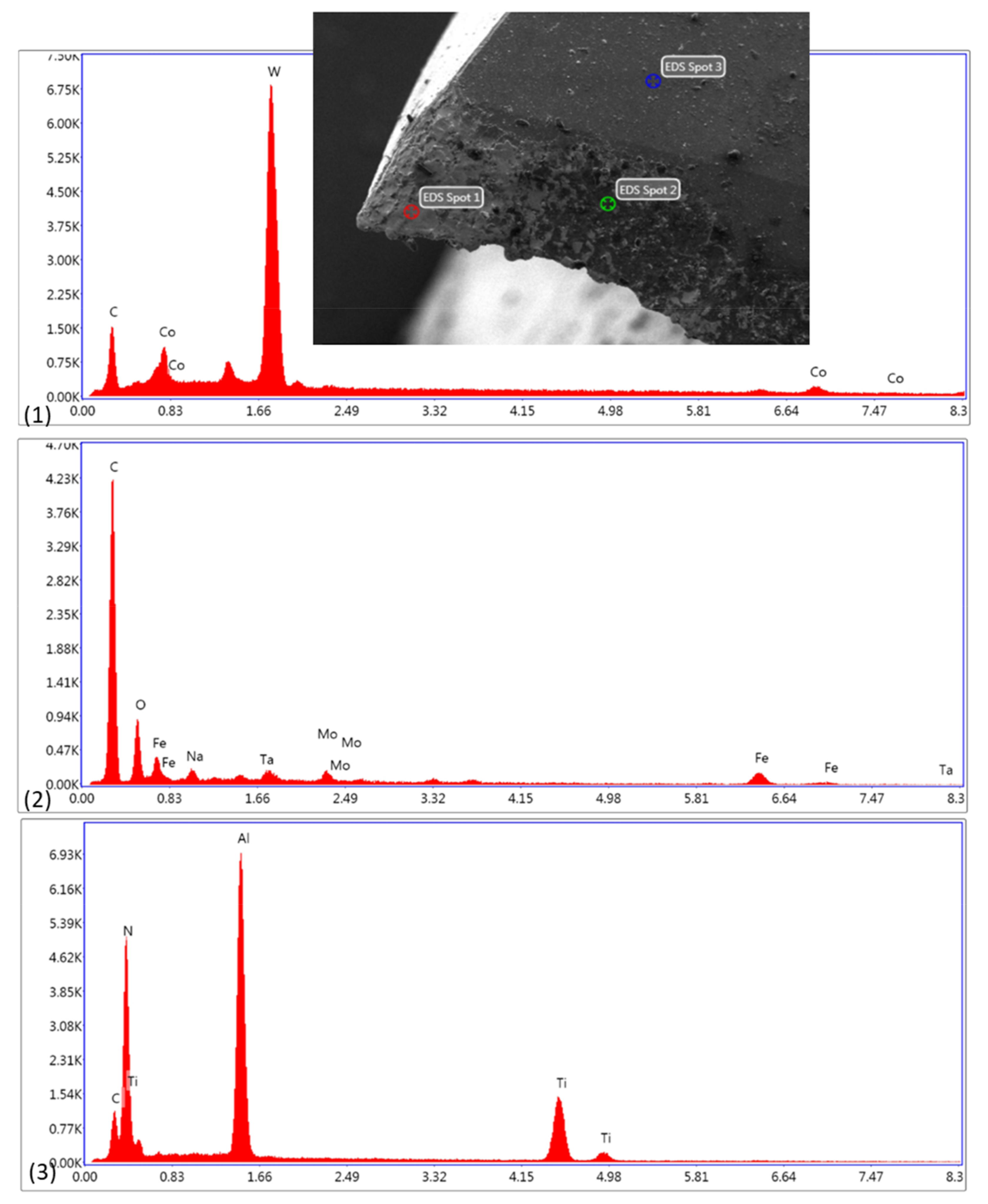
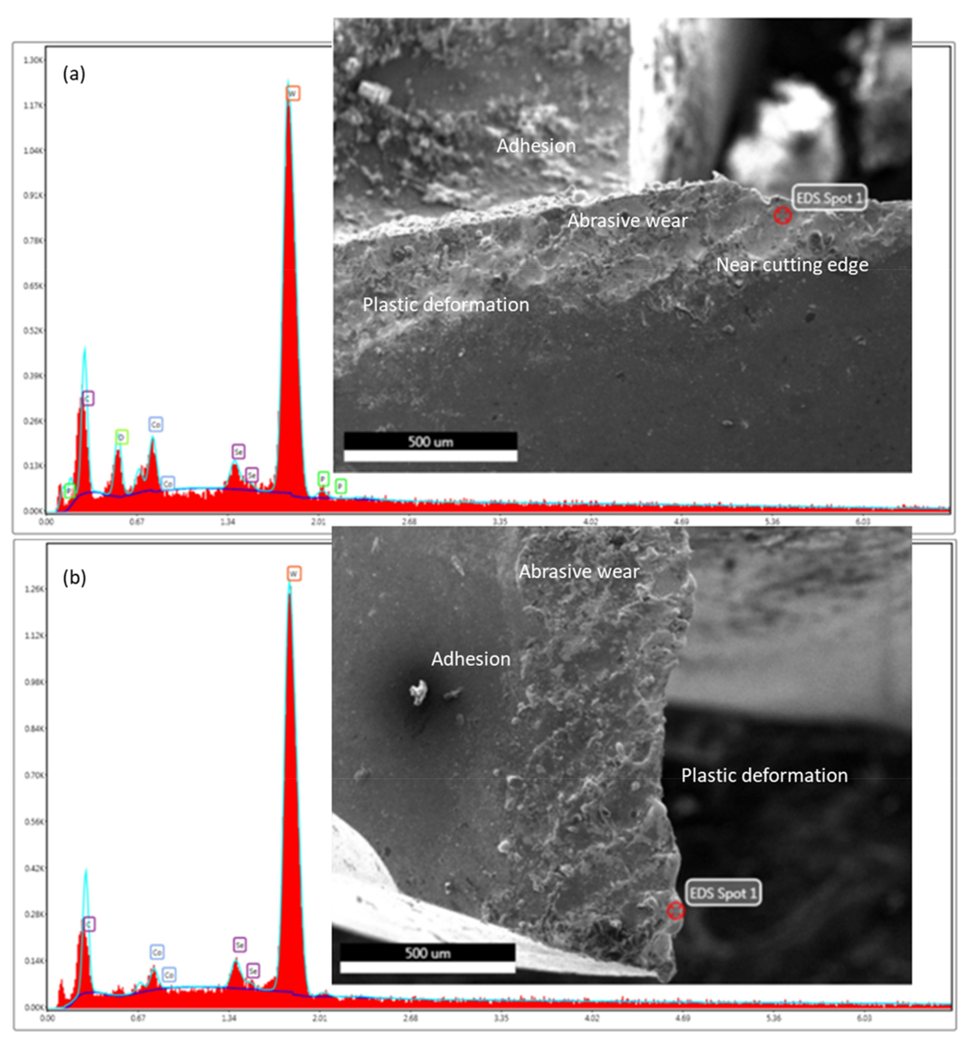
  • The elements W and Co were introduced near the tool nose as a result of adhesion tendency and abrasion, whereas the cutting edge showed evidence of C, O, Fe, and Co with a reduced content of Al and Ti. There was also evidence of Mo on the cutting edge, showing the formation of tribo-film of 1% nano particles. However, the experimental conditions with 0.5% nano particles resulted in low Mo transfer on the tool surface.
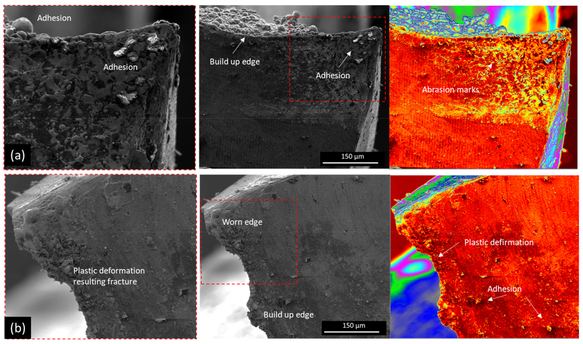
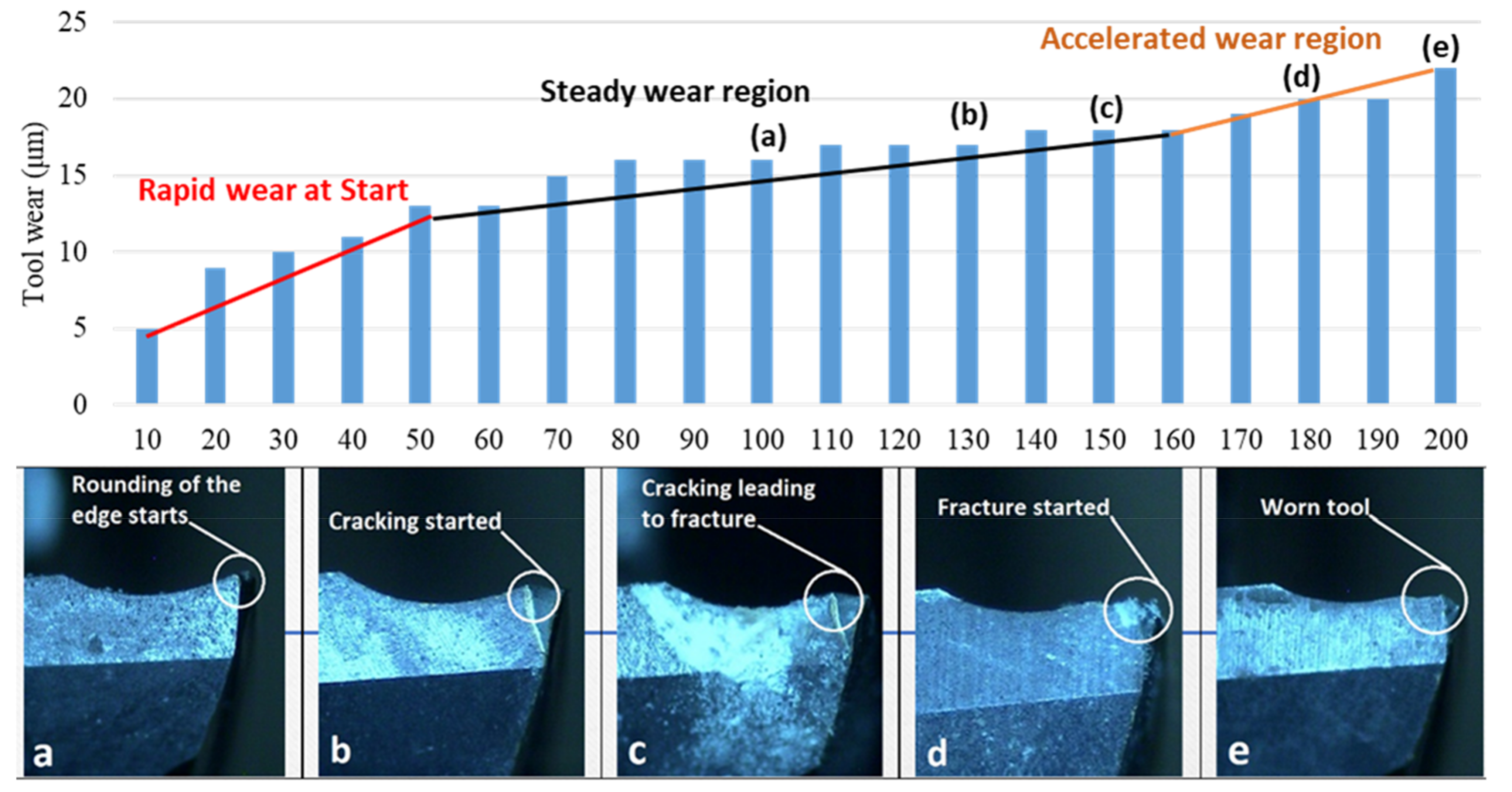
  • In the extended study, abrasion was found to have a major effect on the tool wear mechanism, resulting from long tool engagement and leading to tool fracture. The abrasive wear significantly removed the coating at the cutting edge and severe plastic deformation was observed. Chemical analysis shows the diffusion of C at a high rate as compared to metal elements such as W and Co. The diffusion of elements was found to be one of the major reasons for tool fragility.
  • The chipping mechanism was observed at the cutting edge and was significantly increased between peripheral and frontal edges. The appearance of fractures in this region was associated with local cutting speed and stress at frontal and peripheral edges, respectively.
The current study mainly correlates scientific processes through experimental results and evidence which could also be supported by simulation and artificial intelligence-based process optimization in the future. The measurement of physical properties and performance of the lubricant was focused on the next research phase which will primarily evaluate tribology and tribo-chemistry of MQL systems for aerospace, automotive, and related sectors.

Author Contributions

K.M., conceptualization, data curation, and methodology; M.P.M., conceptualization, formal analysis, and methodology; M.U.F., investigation, and writing—original draft; S.A., formal analysis and writing—review and editing; M.I.A., formal analysis, and writing—review and editing. All authors have read and agreed to the published version of the manuscript.

Funding

Researchers Supporting Project number (RSPD2023R702), King Saud University, Riyadh, Saudi Arabia.

Data Availability Statement

The necessary data used in the manuscript are already present in the manuscript.

Acknowledgments

The authors appreciate the support from Researchers Supporting Project number (RSPD2023R702), King Saud University, Riyadh, Saudi Arabia.

Conflicts of Interest

The authors declare no conflict of interest.

References

  1. Hynes, N.R.J.; Vignesh, N.J.; Jappes, J.W.; Velu, P.S.; Barile, C.; Ali, M.A.; Farooq, M.U.; Pruncu, C.I. Effect of Stacking Sequence of Fibre Metal Laminates with Carbon Fibre Reinforced Composites on Mechanical Attributes: Numerical Simulations and Experimental Validation. Compos. Sci. Technol. 2022, 221, 109303. [Google Scholar] [CrossRef]
  2. Qi, Z.; Ge, E.; Yang, J.; Li, F.; Jin, S. Influence Mechanism of Multi-Factor on the Diameter of the Stepped Hole in the Drilling of CFRP/Ti Stacks. Int. J. Adv. Manuf. Technol. 2021, 113, 923–933. [Google Scholar] [CrossRef]
  3. Xu, J.; El Mansori, M. Experimental Study on Drilling Mechanisms and Strategies of Hybrid CFRP/Ti Stacks. Compos. Struct. 2016, 157, 461–482. [Google Scholar] [CrossRef]
  4. Pereszlai, C.; Geier, N. Comparative Analysis of Wobble Milling, Helical Milling and Conventional Drilling of CFRPs. Int. J. Adv. Manuf. Technol. 2020, 106, 3913–3930. [Google Scholar] [CrossRef]
  5. Mughal, K.; Mughal, M.P.; Farooq, M.U.; Qaiser Saleem, M.; Haber Guerra, R. Helical Milling of CFRP/Ti6Al4V Stacks Using Nano Fluid Based Minimum Quantity Lubrication (NF-MQL): Investigations on Process Performance and Hole Integrity. Materials 2023, 16, 566. [Google Scholar] [CrossRef]
  6. Shu, L.; Li, S.; Fang, Z.; Kizaki, T.; Kimura, K.; Arai, G.; Arai, K.; Sugita, N. Study on Dedicated Drill Bit Design for Carbon Fiber Reinforced Polymer Drilling with Improved Cutting Mechanism. Compos. Part Appl. Sci. Manuf. 2021, 142, 106259. [Google Scholar] [CrossRef]
  7. Ge, J.; Chen, G.; Su, Y.; Zou, Y.; Ren, C.; Qin, X.; Wang, G. Effect of Cooling Strategies on Performance and Mechanism of Helical Milling of CFRP/Ti-6Al-4V Stacks. Chin. J. Aeronaut. 2022, 35, 388–403. [Google Scholar] [CrossRef]
  8. Xu, J.; Ji, M.; Chen, M.; Ren, F. Investigation of Minimum Quantity Lubrication Effects in Drilling CFRP/Ti6Al4V Stacks. Mater. Manuf. Process. 2019, 34, 1401–1410. [Google Scholar] [CrossRef]
  9. Farooq, M.U.; Anwar, S.; Ullah, R.; Guerra, R.H. Sustainable Machining of Additive Manufactured SS-316L Underpinning Low Carbon Manufacturing Goal. J. Mater. Res. Technol. 2023, 24, 2299–2318. [Google Scholar] [CrossRef]
  10. Javid, H.; Jahanzaib, M.; Jawad, M.; Ali, M.A.; Farooq, M.U.; Pruncu, C.I.; Hussain, S. Parametric Analysis of Turning HSLA Steel under Minimum Quantity Lubrication (MQL) and Nanofluids-Based Minimum Quantity Lubrication (NF-MQL): A Concept of One-Step Sustainable Machining. Int. J. Adv. Manuf. Technol. 2021, 117, 1915–1934. [Google Scholar] [CrossRef]
  11. Gao, T.; Li, C.; Wang, Y.; Liu, X.; An, Q.; Li, H.N.; Zhang, Y.; Cao, H.; Liu, B.; Wang, D. Carbon Fiber Reinforced Polymer in Drilling: From Damage Mechanisms to Suppression. Compos. Struct. 2022, 286, 115232. [Google Scholar] [CrossRef]
  12. Jadam, T.; Rakesh, M.; Datta, S. Machinability of Ti–6al–4v Superalloy: Performance of Dry Cutting and Nanofluid MQL (MWCNT-Added Rice Bran Oil). Arab. J. Sci. Eng. 2020, 45, 5673–5695. [Google Scholar] [CrossRef]
  13. Duc, T.M.; Long, T.T.; Van Thanh, D. Evaluation of Minimum Quantity Lubrication and Minimum Quantity Cooling Lubrication Performance in Hard Drilling of Hardox 500 Steel Using Al2O3 Nanofluid. Adv. Mech. Eng. 2020, 12, 1687814019888404. [Google Scholar] [CrossRef]
  14. Sahoo, S.P.; Datta, S.; Roy, T.; Ghosh, S. Machining Performance of Ti6Al4V under Dry Environment, Pressurized Air Supply, and Water-MQL: Analysis of Machining-Induced Vibration Signals and Captured Thermographs. Sādhanā 2021, 46, 208. [Google Scholar] [CrossRef]
  15. Liu, Z.; Chen, M.; An, Q. Investigation of Friction in End-Milling of Ti-6Al-4V under Different Green Cutting Conditions. Int. J. Adv. Manuf. Technol. 2015, 78, 1181–1192. [Google Scholar] [CrossRef]
  16. Pereira, O.; Urbikain, G.; Rodríguez, A.; Fernández-Valdivielso, A.; Calleja, A.; Ayesta, I.; de Lacalle, L.L. Internal Cryolubrication Approach for Inconel 718 Milling. Procedia Manuf. 2017, 13, 89–93. [Google Scholar] [CrossRef]
  17. Mosleh, M.; Shirvani, K.A.; Smith, S.T.; Belk, J.H.; Lipczynski, G. A Study of Minimum Quantity Lubrication (MQL) by Nanofluids in Orbital Drilling and Tribological Testing. J. Manuf. Mater. Process. 2019, 3, 5. [Google Scholar] [CrossRef]
  18. Pereira, O.; Rodríguez, A.; Fernández-Abia, A.I.; Barreiro, J.; de Lacalle, L.L. Cryogenic and Minimum Quantity Lubrication for an Eco-Efficiency Turning of AISI 304. J. Clean. Prod. 2016, 139, 440–449. [Google Scholar] [CrossRef]
  19. Hussein, R.; Sadek, A.; Elbestawi, M.A.; Attia, H. The Effect of MQL on Tool Wear Progression in Low-Frequency Vibration-Assisted Drilling of CFRP/Ti6Al4V Stack Material. J. Manuf. Mater. Process. 2021, 5, 50. [Google Scholar] [CrossRef]
  20. Rodríguez, A.; Calleja, A.; de Lacalle, L.N.L.; Pereira, O.; Rubio-Mateos, A.; Rodríguez, G. Drilling of CFRP-Ti6Al4V Stacks Using CO2-Cryogenic Cooling. J. Manuf. Process. 2021, 64, 58–66. [Google Scholar] [CrossRef]
  21. Ji, M.; Xu, J.; Chen, M.; Mansori, M.E. Effects of Different Cooling Methods on the Specific Energy Consumption When Drilling CFRP/Ti6Al4V Stacks. Procedia Manuf. 2020, 43, 95–102. [Google Scholar] [CrossRef]
  22. Xu, J.; Li, C.; Chen, M.; El Mansori, M.; Paulo Davim, J. On the Analysis of Temperatures, Surface Morphologies and Tool Wear in Drilling CFRP/Ti6Al4V Stacks under Different Cutting Sequence Strategies. Compos. Struct. 2020, 234, 111708. [Google Scholar] [CrossRef]
  23. Senthilkumar, M.; Prabukarthi, A.; Krishnaraj, V. Machining of CFRP/Ti6Al4V Stacks under Minimal Quantity Lubricating Condition. J. Mech. Sci. Technol. 2018, 32, 3787–3796. [Google Scholar] [CrossRef]
  24. Xu, J.; Ji, M.; Davim, J.P.; Chen, M.; El Mansori, M.; Krishnaraj, V. Comparative Study of Minimum Quantity Lubrication and Dry Drilling of CFRP/Titanium Stacks Using TiAlN and Diamond Coated Drills. Compos. Struct. 2020, 234, 111727. [Google Scholar] [CrossRef]
  25. Zou, Y.; Chen, G.; Ren, C.; Ge, J.; Qin, X. Performance and Mechanism of Hole-Making of CFRP/Ti-6Al-4V Stacks Using Ultrasonic Vibration Helical Milling Process. Int. J. Adv. Manuf. Technol. 2021, 117, 3529–3547. [Google Scholar] [CrossRef]
  26. Park, K.-H.; Suhaimi, M.A.; Yang, G.-D.; Lee, D.-Y.; Lee, S.-W.; Kwon, P. Milling of Titanium Alloy with Cryogenic Cooling and Minimum Quantity Lubrication (MQL). Int. J. Precis. Eng. Manuf. 2017, 18, 5–14. [Google Scholar] [CrossRef]
  27. Pereira, O.; Martín-Alfonso, J.E.; Rodríguez, A.; Calleja, A.; Fernández-Valdivielso, A.; López de Lacalle, L.N. Sustainability Analysis of Lubricant Oils for Minimum Quantity Lubrication Based on Their Tribo-Rheological Performance. J. Clean. Prod. 2017, 164, 1419–1429. [Google Scholar] [CrossRef]
  28. Rosnan, R.; Azmi, A.I.; Murad, M.N.; Ali, M.A.M. Evaluation of Coated Carbide Drills When Drilling Nickel-Titanium (NiTi) Alloys with Minimum Quantity Nano-Lubricants. In Intelligent Manufacturing and Mechatronics: Proceedings of SympoSIMM 2020; Springer: Berlin/Heidelberg, Germany, 2021; pp. 299–308. [Google Scholar]
  29. Xu, J.; Ji, M.; Chen, M.; El Mansori, M. Experimental Investigation on Drilling Machinability and Hole Quality of CFRP/Ti6Al4V Stacks under Different Cooling Conditions. Int. J. Adv. Manuf. Technol. 2020, 109, 1527–1539. [Google Scholar] [CrossRef]
  30. AZO Materials. Available online: https://www.amazom.com (accessed on 20 July 2022).
  31. End Mills/Ø 6.000 Mm/E8/Company Std./Solid Carbide/FIRE. Available online: https://webshop.guehring.de/en/000009199780060000 (accessed on 28 April 2023).
  32. Fernández-Valdivielso, A.; López de Lacalle, L.; Urbikain, G.; Rodriguez, A. Detecting the Key Geometrical Features and Grades of Carbide Inserts for the Turning of Nickel-Based Alloys Concerning Surface Integrity. Proc. Inst. Mech. Eng. Part C J. Mech. Eng. Sci. 2016, 230, 3725–3742. [Google Scholar] [CrossRef]
  33. Sha, Z.H.; Wang, Y.; Zhang, S.F. The Influence of Eccentricity on Thrust Force of Helical Milling in Carbon Fiber Composite Holemaking. Appl. Mech. Mater. 2013, 328, 995–999. [Google Scholar] [CrossRef]
  34. Denkena, B.; Boehnke, D.; Dege, J.H. Helical Milling of CFRP–Titanium Layer Compounds. CIRP J. Manuf. Sci. Technol. 2008, 1, 64–69. [Google Scholar] [CrossRef]
  35. Charoo, M.S.; Wani, M.F.; Hanief, M.; Rather, M.A. Tribological Properties of MoS2 Particles as Lubricant Additive on EN31 Alloy Steel and AISI 52100 Steel Ball. Mater. Today Proc. 2017, 4, 9967–9971. [Google Scholar] [CrossRef]
  36. Sekhar, K.C.; Rama Reddy, V.V.; Srikiran, S.; Daniel, M.; Kumar, S. Investigating the Effect of Nano Crystalline MoS2 Particles on the Surface Integrity of Turned Components. Mater. Today Proc. 2017, 4, 7527–7532. [Google Scholar] [CrossRef]
  37. Rahmati, B.; Sarhan, A.A.D.; Sayuti, M. Morphology of Surface Generated by End Milling AL6061-T6 Using Molybdenum Disulfide (MoS2) Nanolubrication in End Milling Machining. J. Clean. Prod. 2014, 66, 685–691. [Google Scholar] [CrossRef]
  38. Uysal, A.; Demiren, F.; Altan, E. Applying Minimum Quantity Lubrication (MQL) Method on Milling of Martensitic Stainless Steel by Using Nano Mos2 Reinforced Vegetable Cutting Fluid. Procedia Soc. Behav. Sci. 2015, 195, 2742–2747. [Google Scholar] [CrossRef]
  39. Puerta-Morales, F.J.; Gomez, J.S.; Fernandez-Vidal, S.R. Study of the Influence of Helical Milling Parameters on the Quality of Holes in the UNS R56400 Alloy. Appl. Sci. 2020, 10, 845. [Google Scholar] [CrossRef]
  40. ul Haq, M.A.; Hussain, S.; Ali, M.A.; Farooq, M.U.; Mufti, N.A.; Pruncu, C.I.; Wasim, A. Evaluating the Effects of Nano-Fluids Based MQL Milling of IN718 Associated to Sustainable Productions. J. Clean. Prod. 2021, 310, 127463. [Google Scholar] [CrossRef]
  41. Liew, W.Y.H. Low-Speed Milling of Stainless Steel with TiAlN Single-Layer and TiAlN/AlCrN Nano-Multilayer Coated Carbide Tools under Different Lubrication Conditions. Wear 2010, 269, 617–631. [Google Scholar] [CrossRef]
  42. Qin, X.; Gui, L.; Li, H.; Rong, B.; Wang, D.; Zhang, H.; Zuo, G. Feasibility Study on the Minimum Quantity Lubrication in High-Speed Helical Milling of Ti-6Al-4V. J. Adv. Mech. Des. Syst. Manuf. 2012, 6, 1222–1233. [Google Scholar] [CrossRef]
  43. Li, H.; He, G.; Qin, X.; Wang, G.; Lu, C.; Gui, L. Tool Wear and Hole Quality Investigation in Dry Helical Milling of Ti-6Al-4V Alloy. Int. J. Adv. Manuf. Technol. 2014, 71, 1511–1523. [Google Scholar] [CrossRef]
  44. Wang, H.; Qin, X.; Li, H.; Tan, Y. A Comparative Study on Helical Milling of CFRP/Ti Stacks and Its Individual Layers. Int. J. Adv. Manuf. Technol. 2016, 86, 1973–1983. [Google Scholar] [CrossRef]
  45. Wang, C.Y.; Xie, Y.X.; Qin, Z.; Lin, H.S.; Yuan, Y.H.; Wang, Q.M. Wear and Breakage of TiAlN-and TiSiN-Coated Carbide Tools during High-Speed Milling of Hardened Steel. Wear 2015, 336, 29–42. [Google Scholar] [CrossRef]
  46. Gutzeit, K.; Bulun, G.; Stelzer, G.; Kirsch, B.; Seewig, J.; Aurich, J.C. Sub-Zero Milling of Ti-6Al-4V–Impact of the Cutting Parameters on the Resulting Forces, Tool Wear, and Surface Quality. Int. J. Adv. Manuf. Technol. 2023, 126, 3367–3381. [Google Scholar] [CrossRef]
  47. Li, J.; Shi, W.; Lin, Y.; Li, J.; Liu, S.; Liu, B. Comparative Study on MQL Milling and Hole Making Processes for Laser Beam Powder Bed Fusion (L-PBF) of Ti-6Al-4V Titanium Alloy. J. Manuf. Process. 2023, 94, 20–34. [Google Scholar] [CrossRef]
  48. Fernández-Vidal, S.R.; Mayuet, P.; Rivero, A.; Salguero, J.; del Sol, I.; Marcos, M. Analysis of the Effects of Tool Wear on Dry Helical Milling of Ti6Al4V Alloy. Procedia Eng. 2015, 132, 593–599. [Google Scholar] [CrossRef]
Figure 1. Details of the stack formation.
Processes 11 01540 g001
Figure 2. Schematic of the machining setup and workpiece fixing details.
Processes 11 01540 g002
Figure 3. Preparation mechanism of nanofluid-based lubricant.
Processes 11 01540 g003
Figure 4. Experimental roadmap to investigate tool wear characteristics.
Processes 11 01540 g004
Figure 5. Parametric trends of tool wear with (ac) axial pitch, tangential feed, and spindle speed Ti6Al4V and (df) spindle speed Ti6Al4V against the axial pitch, tangential feed, and lubrication.
Processes 11 01540 g005
Figure 6. Nanoparticles in the cutting zone.
Processes 11 01540 g006
Figure 7. Parametric trends of tool wear with (a) eccentricity and its two-way effects (b) axial pitch, (c) spindle speed Ti6Al4V, (d) tangential feed, and (e) lubrication.
Processes 11 01540 g007
Figure 8. Parametric trends of tool wear with (a) axial pitch against tangential feed, (b) axial pitch against lubrication, and (c) tangential feed against lubrication.
Processes 11 01540 g008
Figure 9. Tool wear and their promoting mechanisms.
Processes 11 01540 g009
Figure 10. Tool wear mechanisms resulting in low wear at eccentricity level 1, spindle speed (CFRP) 7500 rpm, spindle speed (Ti6Al4V) 1000 rpm, axial pitch 1.5 mm, tangential feed 0.01 mm/tooth, and MoS2 1%.
Processes 11 01540 g010
Figure 11. Mechanistic understanding of the machining process.
Processes 11 01540 g011
Figure 12. Tool wear mechanisms resulting in extreme wear at eccentricity level 2, spindle speed (CFRP) 6500 rpm, spindle speed (Ti6Al4V) 1500 rpm, axial pitch 1.5 mm, tangential feed 0.02 mm/tooth, and MoS2 0.5%.
Processes 11 01540 g012
Figure 13. Mechanistic details of wear-promoting mechanisms.
Processes 11 01540 g013
Figure 14. Adhesive wear (a) eccentricity level 1, spindle speed (CFRP) 7500 rpm, spindle speed (Ti6Al4V) 1000 rpm, axial pitch 1.5 mm, tangential feed 0.01 mm/tooth, and MoS2 1% and (b) eccentricity level 2, spindle speed (CFRP) 6500 rpm, spindle speed (Ti6Al4V) 1500 rpm, axial pitch 1.5 mm, tangential feed 0.02 mm/tooth, and MoS2 0.5%.
Processes 11 01540 g014
Figure 15. Chemical analysis (1, 2, 3, and 4 EDS spots) of tool with low wear resulting from eccentricity level 1, spindle speed (CFRP) 7500 rpm, spindle speed (Ti6Al4V) 1000 rpm, axial pitch 1.5 mm, tangential feed 0.01 mm/tooth, and MoS2 1%.
Processes 11 01540 g015
Figure 16. Chemical analysis (1, 2, and 3 EDS spots) of tool with extreme wear resulting from eccentricity level 2, spindle speed (CFRP) 6500 rpm, spindle speed (Ti6Al4V) 1500 rpm, axial pitch 1.5 mm, tangential feed 0.02 mm/tooth, and MoS2 0.5%.
Processes 11 01540 g016
Figure 17. Extended tool wear mapping at spindle speed (CFRP) 7500 rpm, spindle speed (Ti6Al4V) 1000 rpm, and MoS2 1% NF-MQL (a) 100 holes, (b) 130 holes, (c) 150 holes, (d) 180 holes, and (e) 200 holes.
Processes 11 01540 g017
Figure 18. Chemical and surface analysis at different places as shown in (a) and (b) after 200 holes at spindle speed (CFRP) 7500 rpm, spindle speed (Ti6Al4V) 1000 rpm, and MoS2 1% NF-MQL.
Processes 11 01540 g018
Figure 19. Chip morphology at 1 mm eccentricity and 0.02 tangential feed. (a) 1250 rpm, 0.5% MoS2, and 2 mm axial pitch, (b) 1250 rpm, 0.75% MoS2, and 1.5 mm axial pitch; and at 2 mm eccentricity and 0.02 tangential feed, (c) 1000 rpm, 1% MoS2, and 2 mm axial pitch, and (d) 1500 rpm, 0.5% MoS2, and 1.5 mm axial pitch.
Processes 11 01540 g019
Table 1. A summary of lubrication technologies used to machine CFRP/Ti6Al4V.
Authors, Year and ReferenceCutting Tool and Experimental ConditionsLubrication ConditionsFindings
Ge et al., 2022 [7]Four-flute ultrafine-grained cemented carbide (WC-12%Co) tool; spindle speed, tangential feed per tooth, axial feed, target hole diameter, number of machined holesDry and MQL (synthetic lubricating oil with anti-wear agent, stabilizer, and anti-rust agent)In dry conditions, adhesion and chipping were major drivers of tool wear, whereas in MQL slight adhesion was observed.
Hussein et al., 2021 [19]YG-1 tungsten carbide tool; cutting speed, vibration amplitudeMQL (5% MECAGREEN 550)MQL system assisted extended hole-making campaign without resulting in tool/chip welding phenomenon.
Xu et al., 2019 [8]Uncoated tungsten carbide tool; cutting speed, feed rateDry and MQL (vegetable-based oil)Improvement in surface morphology of machined holes and reduction in tool-wear severity was observed with MQL in comparison to conventional dry cutting.
Rodriguez et al., 2021 [20]CVD diamond-coated carbide tool; number of machined holesDry and CO2With CO2, cutting temperature significantly decreased. However, wear-promoting mechanisms were still of concern.
Ji et al., 2020 [21]PVD TiAlN-coated tool; cutting speed, feed rateDry and MQLFriction of tool with hole walls was significantly reduced by MQL system which resulted in superior surface quality.
Xu et al., 2020 [22]Uncoated tungsten carbide (WC/Co) and CVD diamond-coated tools; cutting speed, feed rate, composite stack sequenceDryThe key wear patterns were observed to be flank wear, abrasion, and adhesion. Similarly, coating peeled off and microchipping resulted in abrupt failure of tools.
Senthilkumar et al., 2018 [23]TG1, TG2, TG3 tools; spindle speed, feed rate, flow rateMQL (LRT30 3226661 cutting fluid with anti-corrosive properties)Low level of flow rate 25 mL/h for hole-making in CFRP, whereas Ti alloy required 75 mL/h to minimize cutting forces and reduce tool wear.
Xu et al., 2020 [24]CVD diamond-coated tungsten carbide and PVD TiAlN tools; cutting speed, feed rateDry and MQL (vegetable-based MICROLUBE 2000 micro-cutting oil)Abrasion wear because of worn edges and adhesion wear due to tool/Ti chip welding were main drivers of tool failure. Coating peeled off and edge fractures were also observed.
Table 2. Details of CFRP ([30] Online Material Property Data Open Access page) and cutting tool ([31] Open Access page by Guhring).
CFRP
DetailsValue
Tensile modulus230 GPa
Fiber thickness0.25 mm
Filament count3000
Filament diameter7 μm
Cutting Tool
DetailsValue
Helix angle30°
Diameter tolerancee8
Tool preparationWithout internal cooling
MaterialSolid carbide
Chamfer angle45°
Back rake angle
Processes 11 01540 i001
Table 3. Parametric variables and their levels.
PropertiesLevelsRationale
Eccentricity (mm)1, 2The eccentricity and tool diameter directly impacts the thrust forces that help us to control the delamination and tool wear rate. The levels are determined based on guidelines by Sha et al. [33].
Spindle speed Ti (rpm)1000, 1250, 1500The levels for the spindle speed of machining CFRP and Ti were selected after the literature review and the trial runs [5].
Spindle speed CFRP (rpm)6500, 7000, 7500
Axial itch (mm)1, 1.5, 2An optimized combination of axial feed per tooth and tangential feed per tooth was used to reduce the effect of cutting forces that have an effect on the diametric variations. The levels used were based on guidelines by Denkena et al. [34] who carried out dry helical milling of CFRP/Ti6Al4V. Using very high axial pitch is the novelty in this research. The micro-focus was on reducing the tool wear, improving the tool life, reducing the machining time, and improving the work quality with minimal errors.
Tangential feed (mm/tooth)0.01, 0.02, 0.03
Lubrication (MoS2) (%wt)0.5, 0.75, 1Molybdenum disulfide (MoS2) is a solid lubricant commonly used in tribological applications due to its excellent lubricating properties [35]. This film acts as a physical barrier between the surfaces, preventing direct metal-to-metal contact and reducing friction [5,17]. Sekhar et al. [36] used 0.5–1.5% MoS2 concentration and found 0.5% as optimal. Rahmati et al. [37] used 0–1% MoS2 concentration during end-milling of aluminum alloys.
Disclaimer/Publisher’s Note: The statements, opinions and data contained in all publications are solely those of the individual author(s) and contributor(s) and not of MDPI and/or the editor(s). MDPI and/or the editor(s) disclaim responsibility for any injury to people or property resulting from any ideas, methods, instructions or products referred to in the content.

