Abstract
The sustained casing pressure (SCP) phenomenon of shale gas and oil wells occurs frequently after fracturing; therefore, in order to assess the cement sheath’s integrity in the vertical well portion, the cement stones were subjected to a compression test under different temperatures and confining pressures to obtain the mechanical parameters of the cement sheath at different well depths. The integrity of the cement ring between the production casing and the intermediate casing was then investigated using the Moore–Coulomb criterion. We also took into account other elements including pump pressure, production casing wall thickness, and cement ring mechanical properties. The results show that (1) the compressive strength, Poisson’s ratio, and Young’s modulus of cement stone vary obviously under different confining pressures and temperature conditions, and the cement stone shows elastic–brittle failure characteristics at 20 °C. The compressive strength, Poisson’s ratio, and Young’s modulus increase with the confining pressure, but the Young’s modulus and compressive strength gradually decrease with the increase in temperature, while the stress–strain curves show obvious plastic failure characteristics at 80 °C and 130 °C. (2) The tangential tensile stress decreases and depth increases from the wellhead to the intermediate casing shoe, while the radial compressive stress of the cement sheath increases. The stress state of the cement sheath changes abruptly at the position of the casing shoe due to the change in casing layers, and under the intermediate casing shoe, the tangential tensile stress changes from tension to compression. When a conventional cementing slurry system is used, the integrity of the cement sheath above the intermediate casing shoe will fail during fracturing. (3) Reducing the pump pressure and increasing casing wall thickness can reduce the tangential and radial stresses of the cement sheath, but the integrity of cement sheath cannot be fully guaranteed. For the cement sheath’s sealing integrity, it is advantageous to decrease the Young’s modulus and raise its strength.
1. Introduction
Due to the persistent rise in the demand for oil and gas, shale gas and oil play an increasing important role in supplementing the shortage of traditional oil and gas resources and adjusting the energy structure. During groundwater and hydrocarbon extraction, wellbore integrity is a key issue for resource production safety, borehole life, and environmental protection (Martirosyan, A. et al., 2021; Ilyushin et al., 2022; Golovina, E et al., 2023; Ilyushin et al., 2023) [1,2,3,4]. One of the manifestations of well integrity failure is wellhead sustained casing pressure (SCP) (Rish, 2005; Jackson et al., 2014; Wang et al., 2014; Guo et al., 2021) [5,6,7,8], and the SCP refers to the phenomenon that the annular pressure at the wellhead is restored to the pressure level before the pressure relief after unloading (Watson and Bachu, 2009) [9]. One of the main reasons for SCP is the failure of the integrity of the cement sheath that results in downhole fluid migrating to the wellhead. The production enhancement process used in the field and the dynamic loading in production can lead to a harsh casing-cement sheath service environment, which can easily induce wellbore integrity problems (Chengzhi, Q. et al., 2022; Turbakov, M. S. et al., 2022; Poplygin, V. et al., 2023) [10,11,12]. For example, the SCP phenomenon in shale gas wells after fracturing is remarkable in the Sichuan shale gas field of China (Yan et al., 2018; Zeng et al., 2019) [13,14], and according to field statistics, as shown in Figure 1, the proportion of wells in which SCP occurred in the annular part between the production casing and intermediate casing (B annular) before fracturing is 14.29% of the total number of shale gas wells; however, the ratio increased to 48.57% after fracturing, showing that hydraulic fracturing has a significant impact on the cement sheath’s ability to seal.
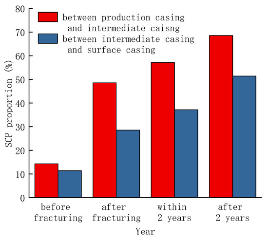
Figure 1.
The ratio of shale gas well with SCP changes with development time.
The cement sheath of shale gas wells is severed in severe working conditions and is in a complex stress state during hydraulic fracturing. The common failure forms of cement sheaths are as follows: (1) tensile failure or compressive failure occurs under high internal pressure in the casing and high in situ stress (Bois et al., 2012) [15]; (2) the accumulation of plastic during cyclic loading causes the contact stress to diminish after the debonding between the cement sheath and the casing, and the micro-annulus is created (Zhang et al., 2017) [16]; and (3) the initial microcracks in the cement sheath continue to expand, resulting in the damage and dilatation of the cement sheath under cyclic loading, and the permeability of the cement sheath increases continuously, which reduces the sealing capacity of the cement sheath (Wang et al., 2019) [17]. The reason for the tensile failure of the cement sheath is that the tangential stress or strain of the cement sheath exceeds its tensile strength or ultimate tensile strain, and the reason for the compressive failure of cement sheath is that the radial stress or strain of the cement sheath exceeds its compressive strength or ultimate compressive strain. During hydraulic fracturing, the casing-cement sheath-formation assembly must withstand the casing’s continuous internal pressure loading and unloading. Under high internal pressure, the cement sheath may bend plastically; however, when the internal pressure of the casing lowers, the displacement of the casing and the cement sheath is not synchronized, which results in the damage of bonding surface with an increase in fracturing sections, and the plastic deformation of the cement sheath increases continuously; when the bonding surface is completely damaged, the micro-annulus will occur.
There are many factors affecting the sealing integrity of cement sheath, including displacement efficiency of the cement slurry to the drilling fluid (Bybee, 2005) [18], the cementing job parameters, wellbore smoothness, the eccentric nature of the casing, working load, thermal stress (Torsæter et al., 2015) [19], and corrosion of downhole fluid to the cement sheath (Gholami et al., 2016) [20]. Many scholars have analyzed the integrity of casing-cement sheath-formation assembly, mainly from the following three aspects: finite element models, physical models, and analytical models. The analytical models are mainly based on thick-cylinder theory to analyze the stress–strain law of casing-cement sheath-formation assembly (Liu et al., 2018) [21]. The casing is considered a linear elastic material, and the cement sheath and formation are considered linear elastic, ideal elastic-plastic, or pore-elastic material. First strength criterion, Mohr–Coulomb criterion, and D-P criterion are among the failure criteria for cement sheaths. On the basis of the streamlined Kirsch equation and the percentage of radial shrinkage of the cement sheath, the effective radial stress was calculated (Oyarhossein and Dusseault, 2015) [22], and the failure possibility of bonding surface under various settings and the relationship between formation and the cement sheath were examined. Based on Lame’s formula, the thermal stress of casing-cement sheath-formation assembly caused by temperature variation can be calculated, and the wellbore integrity, especially the cement sheath’s ability to seal under situations of temperature–pressure coupling, can be analyzed as well (Zhang and Wang, 2017) [23]. In addition to the theoretical analysis, many scholars have carried out physical experiments on cement sheaths to deepen the understanding of the failure mechanism of wellbore integrity. Goodwin and Crook (Goodwin and Crook, 1992) established a sealing detection device to examine how changing pressure and temperature affect the cement sheath’s integrity by circulating hot oil inside the casing [24]. Jackson and Murphey (1993) (Jackson and Murphey, 1993) studied the effect of pressure fluctuation on the fatigue of cement sheath; they believed that increasing the pressure inside the casing would cause plastic strain of the cement sheath, and micro-annulus would occur when the pressure inside the casing decreased; the results provide an initial concept for the theory of cement sheath fatigue failure [25]. The low-cycle fatigue failure mechanism of cement sheaths in high-temperature and high-pressure wells was analyzed, and the fatigue failure of the cement could be divided into three stages, the mechanical properties of cement were optimized based on the experimental results (Yuan et al., 2013) [26]. Ref. (Petersen and Ulm, 2016) [27] analyzed the failure mechanism of the bonding surface under thermal cycling with eccentric casing conditions, and the results showed that casing eccentricity has a considerable effect on the cement sheath’s integrity.
With the rapid development of computer technology and commercial finite element software, the finite element analysis (FEA) has been fully applied in simulating the well integrity failure mechanism under various conditions. According to the cohesive zone approach (CZM) technique, (Wang and Taleghani, 2014) used the finite element method to simulate the debonding mechanism of the bonding surface considering that the downhole fluid migration [7]. Ref. (Shahri et al., 2005) [28] created a finite element model to examine the cement sheath’s failure mechanism under high-pressure and -temperature circumstances; additionally, the impact of casing eccentricity on the integrity of the cement sheath was examined. Ref. (Ichim and Teodoriu, 2017) [29] performed an analysis of the cement sheath’s sealing failure mechanism in thermal recovery wells, and it was deduced that the thermal recovery well should first consider the influence of temperature on the mechanical properties of cement sheath, and secondly, the sealing failure mechanism of the cement sheath under temperature-cycling conditions should be considered.
The in situ stress and formation temperature have significant effects on the mechanical properties of cement sheaths (Zeng et al., 2019) [14]. The Young’s modulus, Poisson’s ratio, and compressive strength under different temperatures and confining pressures show obvious differences. The mechanical parameters obtained from uniaxial triaxial tests at room temperature cannot represent the mechanical properties in reservoir conditions. Previous studies on the integrity of cement sheaths have been mainly based on fluid–solid coupling, temperature–pressure coupling (De Andrade and Sangesland, 2016), downhole fluid corrosion (Carey et al., 2007), and other analytical methods to analyze the effects of in situ stress, formation pressure, temperature variation, casing internal pressure fluctuation, casing wall thickness, cement sheath mechanical parameters, and the bonding surface mechanical parameters on wellbore integrity [30,31]. For example, (Yan et al., 2018) analyzed the integrity of the cement sheath near the landing point of the horizontal section of a shale gas well based on the dynamic change of casing temperature during fracturing. The results showed that the maximum tangential stress or radial stress of the cement sheath increased first and then decreased with the time of fracturing, and reducing the Young’s modulus of the cement sheath can greatly lower the cement sheath’s risk of failure [13]. Li et al. analyzed the influence of wellbore temperature and pressure variation on the integrity of a cement sheath under non-uniform in situ stress; it was found that the change of formation temperature and pressure could lower the contact stress between the cement sheath and casing and could increase the risk of bonding surface debonding [32].
In earlier research, the cement sheath’s integrity at a certain position under different working conditions was considered, and the certain position is generally the horizontal position. As mentioned above, after fracturing, SCP developed in a significant number of shale gas wells, but there was no SCP before fracturing, which means that the fluid at a certain position in the formation can migrate through a continuous path to the wellhead. Cement sheaths in the vertical section serve as one of the most important sealing barriers connecting the shale formation to the ground; it can be considered that there is a risk of integrity failure in the process of fracturing. The risk of SCP can be decreased if the vertical section’s cement sheath’s sealing integrity can be guaranteed. Therefore, it is necessary to analyze the integrity of the cement sheath in the vertical section and determine the countermeasures that have an impact on the vertical section’s cement sheath’s integrity.
This essay has the following structure: First, uniaxial, triaxial compression, and Brazilian splitting experiments for conventional cement stones are carried out, and the Young’s modulus, Poisson’s ratio, internal friction angle, and cohesion stress of cement stones under different conditions are obtained. Second, based on the experimental results, the construction of the casing-cement sheath at various well depths is modeled using finite elements, and the Mohr–Coulomb criterion is used to assess the integrity of the cement sheath between the production casing and intermediate casing. At last, the factors affecting the integrity of cement sheath are analyzed, including pump pressure, casing wall thickness, and cement sheath mechanical characteristics.
2. Cement Experiment
The temperature and pressure of the vertical section of shale gas wells vary widely, and the mechanical properties of cement stone are obviously affected by temperature and confining pressure, while the mechanical parameters of a cement sheath near the wellhead are quite different from those near the bottom of the well. Therefore, it cannot be considered that the mechanical parameters of cement sheaths in the whole shale gas wellbore are the same. Taking a shale gas well as an example, the measured depth of the well is 5015 m, and the vertical depth is 3750 m; the depth distribution of surface casing shoe, intermediate casing shoe, and production casing shoe is 950 m, 3438 m, and 5005 m, respectively. In order to simplify the experiment and calculation, we took three target points from 0 m to 950 m, and the corresponding well depths are 0 m, 475 m, and 950 m, respectively; the integrity cement sheath at the three target points was analyzed to represent the cement sheath’s integrity between 0 m and 960 m. Similarly, we took three target points from 970 m to 3438 m, and the corresponding depths are 970 m, 2199 m, and 3438 m, respectively. The integrity cement sheath at the three target points was analyzed to depict the consistency of the cement sheath from 970 m to 3438 m; then, we took one target point at the depth of 3448 m to analyze the cement sheath’s integrity close to the intermediate casing shoe.
The formation temperature gradient is 2.8 °C/100 m; the formation temperature at 0 m and 475 m is 20 °C and 33.5 °C, respectively; the formation temperature and confining pressure is relatively low; and the effect of temperature and confining pressure on the mechanical properties of cement sheath can be ignored, and only the uniaxial compression test is required. When the well depth is 950 m and 960 m, the formation temperature is 46.6 °C and 46.9 °C, respectively, and temperature’s impact on the cement sheath is not significant, but the confining pressure of the cement sheath during the solidification process becomes higher. Considering the confining pressure loading capacity of the triaxial compression testing machine and simplifying the test, the confining pressure of test was set to be 15 MPa.
When the well depth is 2199 m and 3438 m, the formation temperature is 81.6 °C and 116.3 °C, respectively. The influence of formation temperature on the mechanical properties of the cement sheath cannot be ignored. Therefore, triaxial compression tests of the cement sheath at the 2199 m and 3438 m locations were carried out at the temperature of 80 °C, confining pressure of 15 MPa, temperature of 130 °C, and confining pressure of 15 MPa, respectively. There are two reasons why the temperature is 130 °C instead of 116.6 °C. First, the difference between test temperature and formation temperature is only 13.4 °C, which is not enough to affect the mechanical properties of the cement sheath. Second, the bottom hole temperature of the shale gas well is 127.9 °C, so the temperature is determined to be 130 °C. For the cement sheath at a 3448 m well depth, because the well depth is similar to that at 3438 m, the experiment was carried out according to the experimental conditions at 3438 m.
The conventional cement slurry formula used in shale gas wells was used in the test, and the details are as follows: G-grade oil well cement Gezhouba sanxia brand (500 g), 12.7 mm silicon powder containing more than 90% silicon (175 g), liquid dehydrating agent (20 g), and water (263.5 g) were used. The cement stones were maintained with a water bath for 3 days at 130 °C and 20.7 MPa and then cooled and preserved at 27 °C. The sample parameters are shown in Table 1.

Table 1.
The test scheme and cement stone parameters.
2.1. Uniaxial Compression Test
The stress–strain curve of cement stone at 20 °C and the morphology of the sample after failure are shown in Figure 2. As can be seen from Figure 2a, the axial strain of the cement stone can be distinguished into three stages. Stage 1 indicates that the initial voids and microcracks in the cement are compacted, and the stress–strain curve grows slowly; in stage 2, the stress–strain curve of cement stone is basically straight, and the slope of the curve represents the Young’s modulus. In stage 3, the curve veers off from the original straight line and bends downward until it breaks down. The peak stress, Young’s modulus, and Poisson’s ratio are 51.9 MPa, 7.66 GPa, and 0.148, respectively.
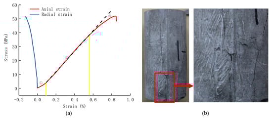
Figure 2.
Results of uniaxial compression test. (a) Stress–strain curve of cement stone under uniaxial compression; (b) morphology of cement stone after uniaxial compression test.
2.2. Triaxial Compression Test
Triaxial compression tests were carried out under the confining pressure of 15 MPa and the temperature of 20 °C, 80 °C, and 130 °C; the experimental results and morphology of cement stone under different conditions are shown in Figure 3. As shown in the red line in Figure 3a, the triaxial compression test at 20 °C shows that the deviating stress increases linearly with the strain at first, then veers off the straight path due to the damage of the cement, and finally reaches the peak point, which decreases gradually and tends to a stable value. The peak stress, Young’s modulus, and Poisson’s ratio are 56.8 MPa, 8.37 GPa, and 0.191, respectively. Compared with uniaxial compression test, the plastic deformation ability of cement stone is enhanced.
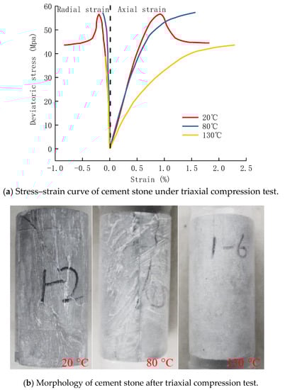
Figure 3.
Results of triaxial compression test.
When the temperature is 80 °C, the stress–strain curve first presents a straight-line state, then deviates from the straight line because of the internal damage, and finally tends to the level, showing the ideal elastic-plastic characteristics. The peak stress, Young’s modulus, and Poisson’s ratio are 57.9 MPa, 7.44 GPa, and 0.083, respectively. Compared with the uniaxial compression test, the plastic deformation ability of cement stone is enhanced as well.
When the temperature is 130 °C, the elastic-plastic law of cement stone is similar to that at 80 °C, but the plastic deformation characteristics are more obvious. The peak stress, Young’s modulus, and Poisson’s ratio are 44.3 MPa, 4.39 GPa, and 0.062, respectively. It can be concluded that with the increase in temperature, the plastic deformation ability of the cement sheath increases continuously. Even if the same cement slurry system is used in the cementing job, the mechanical behavior of the cement sheath varies greatly due to the confining pressure and temperature at different depth of wells. Therefore, it is necessary to calculate the overall wellbore’s cement sheath’s stress state in combination with the test results.
2.3. Brazilian Split Test
Through the above-mentioned experiment, the failure law of cement stone under the casing’s high internal pressure and high in situ stress can be obtained. However, the failure forms of the cement sheath also include tensile failure. Generally, the tensile strength of cement stone can be measured by the Brazilian splitting test, and the test results of the Brazilian splitting tests at 20 °C are shown in Figure 4. In the test, the thickness and diameter of the cement paste are 6.87 mm and 24.26 mm, and according to Equation (1), the tensile strength of cement paste can be calculated as 4.2 MPa. Unlike triaxial compression tests at different temperatures and confining pressures, it is very difficult to conduct the Brazilian splitting test on cement paste at different temperatures and confining pressures, as this is mainly limited by the physical structure of the test machine.
where σt represents the tensile strength (MPa); Pc represents critical load (KN), which is the peak value of the displacement load curve in Figure 4; D represents diameter (mm); t represents thickness (mm).
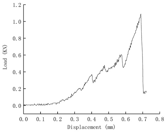
Figure 4.
Results of Brazilian split test.
3. Establishment of Finite Element Model
Considering the large vertical well depth span of shale gas wells, in order to simplify the model, the plane strain model is used instead of the three-dimensional finite element model. According to the well structure of a shale gas well, the finite element models of casing-cement sheath-formation assembly at different well depths are different, which is split into three parts. ① The finite element calculation model for the finite element models above the surface casing shoe, which are primarily used to analyze the integrity of the cement sheath between the wellhead and the surface casing shoe, is illustrated in Figure 5a. ② The finite element model is illustrated in Figure 5b, and it extends from the surface casing shoe to the intermediate casing shoe. It is primarily used to examine the integrity of the cement sheath beneath the surface casing shoe and above the intermediate casing shoe. ③ The main purpose of the casing-cement sheath-formation assembly is to examine the cement sheath’s integrity close to the location of the intermediate casing shoe. The finite element model is shown in Figure 5c.
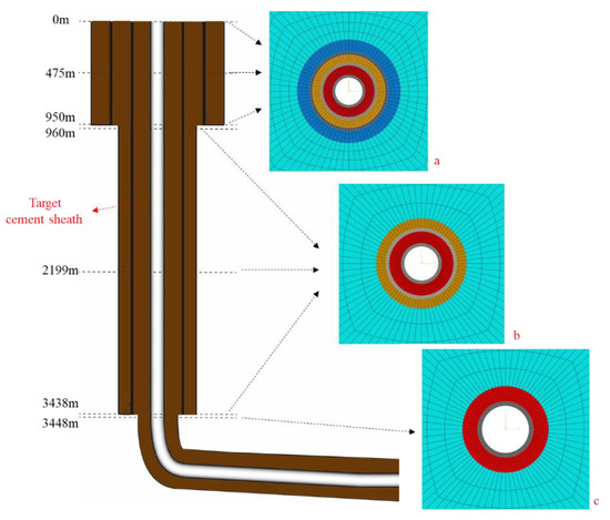
Figure 5.
Well structure and finite element model. (a): wellbore assembly for first spudding; (b): wellbore assembly for second spudding; (c): wellbore assembly for third spudding.
The stress state of the cement sheath between the production casing and the intermediate casing can be analyzed by changing the in situ stress, the internal pressure of the casing, the material parameters of the casing-cement sheath-formation, and the geometric parameters under different spuddings. The geometric and mechanical parameters of the casing, cement sheath, formation, and in situ stress in different well depths are shown in Table 2, Table 3 and Table 4.
Table 2.
Geometric and mechanical parameters of casing/cement sheath/formation assembly.
Table 3.
Mechanical parameters of cement sheath.
Table 4.
Mechanical parameters of formation.
3.1. Contact and Boundary Conditions
The contact mode between the casing and cement sheath and the cement sheath and the formation was set to be tie contact, and the size of the formation is 1000 × 1000 mm to ignore the influence of formation size on the accuracy of the model. Displacement constraints were applied to the outer boundary of the formation, and in situ stress was applied to the formation. The casing inner pressure was applied to the inner wall of the casing, which can be calculated by Equation (2).
where Pi reflects the pressure inside the casing (MPa), P0 represents pump pressure (MPa), ρ represents density (1000 kg/m³), g represents gravity acceleration (10 m/s2), and h represents vertical depth (m).
3.2. Constitutive Equation and Failure Criterion
According to the triaxial compression test of cement stone under different conditions, it can be concluded that the cement stone shows brittle failure characteristics at 20 °C without confining pressure, and the failure of cement stone can be judged by the first strength criterion. When the cement stone is in a certain confining pressure state, the Mohr–Coulomb criterion is generally used to judge the integrity. It is necessary to analyze the Young’s modulus, Poisson’s ratio, internal friction angle, and cohesion strength from the results of the triaxial compression test when using the Mohr–Coulomb criterion. The Young’s modulus and Poisson’s ratio of the cement under different conditions were analyzed previously, taking the compressive strength of cement stone at 20 °C, the triaxial compression test at 20 °C, and the confining pressure of 15 MPa as an example, the calculation method of the internal friction angle and cohesion strength is described as follows. The inclination of the common tangent is the internal friction angle, and the intersection point between the common tangent and the longitudinal axis is the cohesion strength.
The cement sheath’s radial and tangential stresses can be obtained by the finite element model, and tangential tension and radial stress both contribute to cement sheath failure. The criteria in Table 5 are used to determine the integrity of the cement sheath.
Table 5.
Mohr-Coulomb criteria.
3.3. Model Validation
In order to verify the finite element model, the physical simulation experiment was performed using a full-size cement sheath sealing-capacity-evaluation apparatus. We followed the experiment’s fundamental tenet: For the purpose of simulating the casing-cement sheath-formation assembly, the casing-cement sheath-outer casings were employed. In the fracturing process, the assembly of the cement sheath was as shown in Figure 5 (Lian et al., 2020) [33], and then, the pressure was loaded into the casing when passing the pressure system. To track the stress status of the cement sheath, a stress sensor was positioned between the cement sheath and the casing interface. The outer casing has the following dimensions: outside diameter, 244.5 mm; inner diameter, 193.7 mm; height, 1200 mm; and the grade of the inner and outer casing is P110 and N80, respectively. The size of the casing is as follows: outer diameter, 139.7 mm; inner diameter, 124.26 mm; height, 1200 mm. The case has a Young’s modulus and a Poisson’s ratio of 210 GPa and 0.3, respectively. The Young’s modulus and Poisson’s ratio of the cement sheath were obtained from uniaxial compression test. The casing internal pressure was 70 MPa during the experiment, and the experimental device diagram, experimental results, and numerical results are shown in Figure 6 and Figure 7.
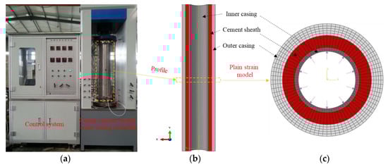
Figure 6.
Cement sheath integrity testing device and the corresponding numerical model. (a) Cement sheath integrity; (b) profile of casing-cement; (c) plain strain model testing device for the sheath outer casing assembly.
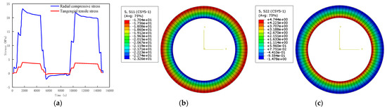
Figure 7.
Comparison between the results of physical experiment and numerical simulation. (a) Measuring result of cement sheath; (b) numerical results of radical stress; (c) numerical results of tangential stress.
Two cycles of cyclic pressure loading were carried out during the physical experiment. The process was 0MPa-70MPa-0MPa-70MPa-0MPa, and as a result, Figure 7a shows the cement sheath’s stress periodic changes. The radial pressure stress of the cement sheath was measured by a stress sensor to be 22.7 MPa and the tangential tension stress to be 4.6 MPa when the inner pressure of the casing was loaded to 70 MPa. The radial compressive stress and tangential tensile stress at the inner wall of the cement sheath were 23.26 MPa and 4.74 MPa, respectively, when the casing’s internal pressure was 70 MPa, as can be seen in Figure 6b,c in the numerical calculation model. The numerical calculation’s findings differed from the actual testing results by 2.4% and 3.0%, respectively, demonstrating the accuracy of the meshing, material characteristics, and contact interactions.
3.4. Case Analysis
Next, we set the wellhead pump pressure to be 85 MPa, according to the experimental results of the cement stone experiment, combined with the finite element model with different well depths as mentioned above. We calculated the Mohr–Coulomb judgment value and the tangential and radial stresses of the cement sheath between the production casing and intermediate casing at various well depths; the results are shown in Figure 8.
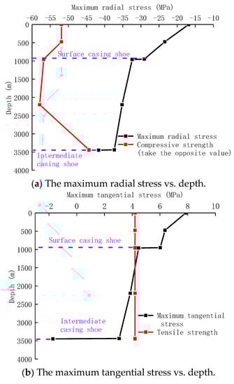
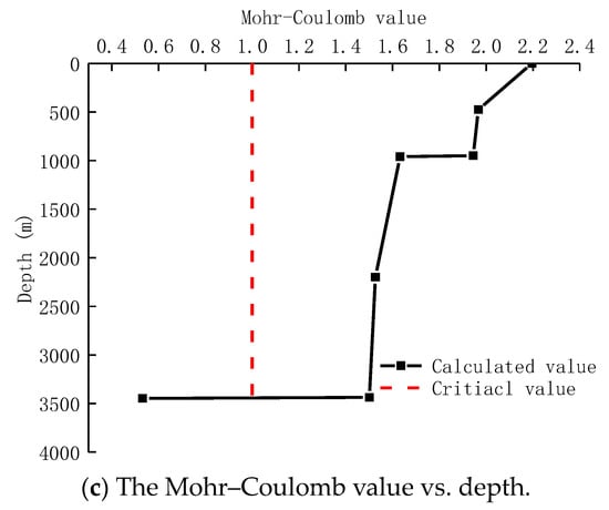
Figure 8.
The law of the stress state of the cement sheath varies with depth.
The maximum radial stress of the cement sheath increases with the increase in well depth, as can be shown in Figure 8. However, the maximum tangential stress decreases gradually with the increase in well depth, and when the well depth is 3448 m, the maximum tangential stress even reverses from tension to compression. The main reason is that with the increase in well depth, the in situ stress and the casing pressure increase, and it causes the cement sheath’s degree of compression to grow as the well’s depth increases. For the cement sheath’s tangential stress maximum, the enclosing effect of the in situ stress on the cement gradually increases with the increase in the depth, leading to a gradual decrease in the tangential stress of the cement sheath. When the casing layer changes, the stress of cement sheath will change abruptly; for example, comparing the well structure at 950 m and 960 m, it was found that the well structure at the 960 m depth has one less layer of surface casing, and the in situ stress is more easily transferred to the cement sheath, and the encapsulation effect of in situ stress on the cement sheath is stronger, which increases the stress that the cement sheath bears in the radial direction. Thus, the maximum tangential stress is reduced. It can be considered that the risk of failure of a cement sheath under radial compression increases with the increase in well depth, and the risk of failure of a cement sheath under tangential tension decreases with the increase in well depth.
Based on the findings of the Mohr–Coulomb criterion, it can be seen that the Mohr–Coulomb determination value decreases gradually with the increase in well depth, but the values are all greater than 1, and the sealing integrity of the cement sheath will fail under this condition, which creates the continuous path for downhole fluid migrating to wellhead.
4. Stress Sensitivity Analysis of Cement Sheath
In order to study the factors affecting the integrity of the cement sheath, the following aspects are analyzed in this paper. Firstly, the variation of contact stress of a cement sheath with depth during the fracturing process was analyzed, and then, the influence of pump pressure and the production casing wall thickness on the integrity of the cement sheath was analyzed. Lastly, a new cement slurry formulation was developed. The compressive strength and tensile strength of cement paste under different elastic materials were measured, and new cement sheath parameters were used to examine the cement sheath’s integrity in the vertical section.
4.1. Change of Contact Stress of Cement Sheath with Well Depth
The in situ stress and the casing’s inner pressure typically rise as the well depth increases. However, shale gas wells have different spuddings in the vertical section. Little research has been done on the contact stress variation with well depth on the bonding surface. Keeping the parameters of the above finite element model unchanged, Figure 9 shows the contact stress variation of the first bonding surface (casing to cement) and the second bonding surface (cement to formation).
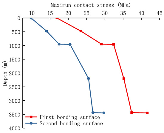
Figure 9.
The contact stress on bonding surface varies with well depth.
As it can be seen from Figure 9, the contact stress of the first bonding surface is greater than that on the second bonding surface, and the difference increases with the increase in well depth. At the position of the casing shoe, the contact stress on the bonding surface will change abruptly. For example, there are casing shoes at 960 m depth and 3438 m depth, while the contact stress on the bonding surface increases. The reason is that there are two casing layers in the well structure when the well depth is 960 m, but there are three casing layers in the well structure when the well depth is 950 m; therefore, the ability of a two-layer casing to resist in situ stress obviously decreases, and the in situ stress can be communicated to the cement sheath more effectively, increasing the contact stress on the cement sheath.
4.2. Pump Pressure
According to Equation (1), when the surface pump pressure changes, the inner pressure of the casing will change, which will obviously change the stress state of the cement sheath. In the actual fracturing process, due to the different features of target formation and the value of in situ stress, there will be some difference in pump pressure; therefore, it is important to analyze how it affects the tension on the cement sheaths. Based on the basic example, the cement sheath’s stress fluctuation law was examined for pump pressures of 65 MPa, 75 MPa, and 85 MPa. At the same time, the Mohr–Coulomb determination value was calculated. The calculation results are shown in Figure 10.
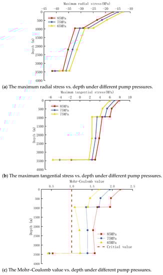
Figure 10.
Variation of stress of cement sheath under different pump pressures.
From Figure 10, it can be seen that the cement sheath’s stress varies depending on the pump pressure. The lower the pump pressure, the lower the cement sheath’s maximum tangential stress at the same depth. For example, when the pump pressure was reduced from 85 MPa to 65 MPa, the maximum tangential stress at 3438 m decreased from 3 MPa to 1.75 MPa. However, even if the pump pressure is 65 MPa, the Mohr–Coulomb judgment value of cement sheath at 0–3438 m exceeds 1. Therefore, reducing the pump pressure cannot significantly reduce the failure risk of the cement sheath.
4.3. Casing Wall Thickness
In general, the deeper the shale gas well, the higher the wall thickness of the casing, and the main reason is that the higher the pump pressure, the higher the internal pressure acting on the inner casing wall, and the casing with high wall thickness can improve the internal pressure strength. Keeping the wellhead pump pressure at 85 MPa, and the thickness of the production casing was set to be 10.54 mm, 12.54 mm, and 14.54 mm, respectively. The maximum tangential stress, maximum radial stress, and the Mohr–Coulomb judgment value of cement sheath were calculated. The calculation results are shown in Figure 11.
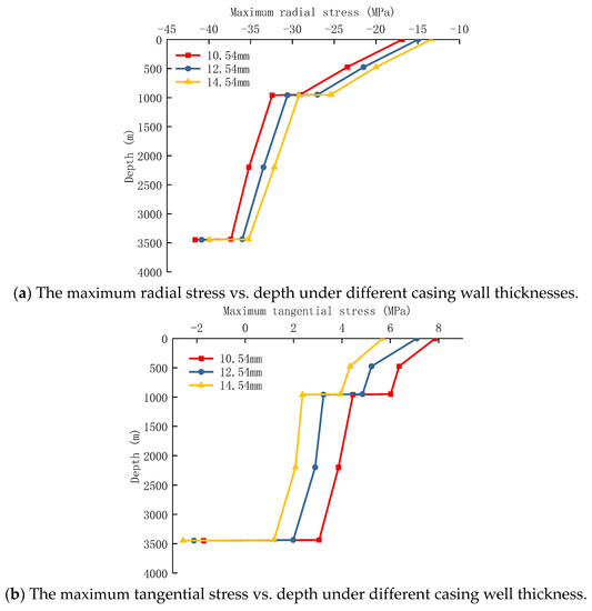
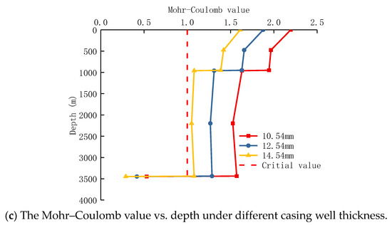
Figure 11.
Variation of stress of cement sheath under different casing thicknesses.
Figure 11 depicts the stress condition of the cement sheath under various thicknesses of production casing. As the thickness of the casing wall increases, the cement sheath’s radial and tangential stress at the same well depth decrease. At a depth of 0 m, the tangential tensile stress of the cement sheath reduces from 7.86 MPa to 5.68 MPa as the casing wall thickness grows from 10.54 mm to 14.54 mm. At a depth of 3438 m, the tangential tensile stress of the cement sheath decreases from 3.06 MPa to 1.19 MPa. As a result, it is advantageous to increase the wall thickness of the production casing in the vertical section to lower the risk of cement sheath failure. The cement sheath will still break during the fracturing phase despite the casing wall thickness being 14.54 mm according to the requirement. It can be considered that increasing the thickness of the production casing is beneficial for reducing the risk of cement sheath failure.
4.4. Mechanical Properties of Cement Sheath
The effects of wellhead pump pressure and casing wall thickness on the integrity of the cement sheath were examined in the section above. It can be considered that reducing pump pressure and increasing casing wall thickness are helpful for reducing the cement sheath’s stress state; however, the vertical well’s cement sheath’s integrity cannot be guaranteed during fracturing. However, the wellhead pump pressure is affected by the in situ stress of the target formation and the mechanical properties of the shale rock, and its reduction is limited. Therefore, it is necessary to study the influence of the mechanical properties of the cement sheath on the stress state of the cement sheath. The Young’s modulus is one of the crucial mechanical characteristics of the cement sheath; according to prior research, it is more advantageous for relieving the stress situation when the Young’s modulus of the cement sheath is lower. However, when the Young’s modulus of the cement sheath is reduced, the compressive strength and tensile strength will decrease as well, and the reason is that when reducing the Young’s modulus of the cement sheath, it is necessary to add to the cement slurry a certain amount of fibers and latex with strength lower than that of the original formula in order to form the cement sheath. Therefore, when the Young’s modulus of the cement sheath decreases, its strength will generally decrease. Field engineers have been trying to find ways to minimize the Young’s modulus of the cement sheath while maintaining or even increasing its strength.
As shown in Figure 12, taking the cement sheath with 4% and 6% organic elastic material as an example, the production casing wall thickness was set to 13.49 mm and the surface pump pressure to 85 MPa. According to the prior calculation approach, the stress state of the cement sheath between the production casing and technical casing during the fracturing process was examined. The calculation results are as follows:
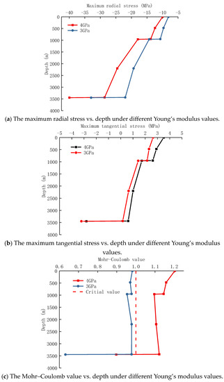
Figure 12.
Variation of stress of cement sheath under different Young’s modulus values.
5. Discussion
In this study, the stress distribution characteristics of the cement ring in the whole wellbore when G-grade cement is used as the cementing material were analyzed, and the failure of the cement ring in the whole wellbore was determined based on the Moore–Coulomb criterion. This study provides an analysis of the idea of cement ring integrity in the whole wellbore. Due to the limitations of the test conditions, cementitious materials with multiple additions were not analyzed. This will be the focus of the next work, in which we will seek to obtain the mechanical properties of cementite under different formulations through testing and to quantify the analysis of this cementing material on the whole-wellbore scale so as to finally achieve the purpose of reducing the cement ring failure length and reducing the risk of carrying pressure in the annulus.
6. Conclusions
The finite element models of casing-cement sheath-formation assembly at various well depths in the vertical section were established taking into account the difference in mechanical parameters of the cement sheath at various depths in order to analyze the sealing failure mechanism of the cement sheath during hydraulic fracturing. Sensitivity analyses of the cement sheath’s integrity were performed, including pump pressure, production casing thickness, and cement sheath mechanical parameters. The following conclusions were drawn:
- (1)
- On cement stone used in shale gas wells, uniaxial and triaxial compression tests were conducted, and the impact of temperature on the stress–strain curve of cement stone was investigated. The findings demonstrate that the cement stone exhibits notable elastic-brittle properties at 20 °C; with an increase in confining pressure, the cement stone’s Young’s modulus and compressive strength rise; with an increase in temperature, however, the Young’s modulus and Poisson’s ratio gradually fall, and the cement stone exhibits plastic failure characteristics; therefore, when assessing the integrity of the entire wellbore cement sheath, it is not possible to assume that the mechanical parameters of cement sheaths at various depths are identical due to variations in temperature and pressure within the wellbore. Instead, a thorough analysis is required;
- (2)
- With respect to well depth, the cement sheath’s stress state changes. The findings revealed that the cement sheath’s radial compressive stress increased with increasing well depth, its tangential tensile stress decreased with increasing well depth, and its stress state abruptly changed at the position of the casing shoe due to the change of casing layers. Based on the Mohr–Coulomb criterion, the integrity of the cement sheath was judged. The results show that the high internal pressure of the casing can damage the integrity of the cement sheath in a conventional cement slurry system during fracturing;
- (3)
- Reducing the pump pressure and increasing casing wall thickness can lessen the radial and tangential stresses on the cement sheath. However, the integrity of a cement sheath cannot be fully guaranteed. A new formula of cement slurry was designed, which can ensure the compressive strength and tensile strength while lowering the Young’s modulus. The method of increasing the wall thickness of the production casing and reducing the Young’s modulus of the cement sheath can ensure that the Mohr–Coulomb criterion value of the cement sheath is less than 1, and the sealing ability of cement sheath is guaranteed.
Author Contributions
Conceptualization, software, writing—original draft preparation: Z.L. and J.L.; software: W.L., S.X. and X.W.; writing—review and editing: H.Z. and L.S. All authors have read and agreed to the published version of the manuscript.
Funding
This research was funded by (National Natural Science Foundation of China) grant number (52204018, U19B6003), (Innovative Environment Construction Plan (Innovative Talents) Project at Karamay) grant number (20212022hjcxrc0029, 20212022hjcxrc0037), (Research Foundation of China University of petroleum (Beijing) at Karamay) grant number (XQZX20220006).
Institutional Review Board Statement
Not applicable.
Informed Consent Statement
Not applicable.
Data Availability Statement
Not applicable.
Conflicts of Interest
The authors declare no conflict of interest.
References
- Martirosyan, A.V.; Kukharova, T.V.; Fedorov, M.S. Research of the Hydrogeological Objects’ Connection Peculiarities. In Proceedings of the 2021 IV International Conference on Control in Technical Systems (CTS), Saint Petersburg, Russia, 21–23 September 2021; pp. 34–38. [Google Scholar]
- Ilyushin, Y.V.; Asadulagi, M.-A.M. Development of a Distributed Control System for the Hydrodynamic Processes of Aquifers, Taking into Account Stochastic Disturbing Factors. Water 2023, 15, 770. [Google Scholar] [CrossRef]
- Golovina, E.; Shchelkonogova, O. Possibilities of Using the Unitization Model in the Development of Transboundary Groundwater Deposits. Water 2023, 15, 298. [Google Scholar] [CrossRef]
- Ilyushin, Y.V. Development of a Process Control System for the Production of High-Paraffin Oil. Energies 2022, 15, 6462. [Google Scholar] [CrossRef]
- Rish, W. A probabilistic risk assessment of class I hazardous waste injection wells. Dev. Water Sci. 2005, 52, 93–135. [Google Scholar]
- Jackson, R.B.; Vengosh, A.; Carey, J.W.; Davies, R.J.; Darrah, T.H.; O’Sullivan, F.; Pétron, G. The Environmental Costs and Benefits of Fracking. Annu. Rev. Environ. Resour. 2014, 39, 327–362. [Google Scholar] [CrossRef]
- Wang, W.; Taleghani, A.D. Simulating Multizone Fracturing in Vertical Wells. J. Energy Resour. Technol. 2014, 136, 042902. [Google Scholar] [CrossRef]
- Guo, M.L.; Cui, S.H.; Dong, Z.; Meng, W.B.; Zhao, H.J.; Zhang, Q. Establishment and research of annular pressure model for deepwater gas wells. Xinjiang Oil Gas 2021, 17, 40–45. [Google Scholar]
- Watson, T.L.; Bachu, S. Evaluation of the Potential for Gas and CO2 Leakage Along Wellbores. SPE Drill. Complet. 2009, 24, 115–126. [Google Scholar] [CrossRef]
- Chengzhi, Q.; Guzev, M.A.; Poplygin, V.V.; Kunitskikh, A.A. Predicting the permeability of the near-bottomhole zone during wave impact. Записки Гoрнoгo института 2022, 258, 986–995. [Google Scholar] [CrossRef]
- Turbakov, M.S.; Kozhevnikov, E.V.; Riabokon, E.P.; Gladkikh, E.A.; Poplygin, V.V.; Guzev, M.A.; Jing, H. Permeability Evolution of Porous Sandstone in the Initial Period of Oil Production: Comparison of Well Test and Coreflooding Data. Energies 2022, 15, 6137. [Google Scholar] [CrossRef]
- Poplygin, V.; Qi, C.; Guzev, M.; Kozhevnikov, E.; Kunitskikh, A.; Riabokon, E.; Turbakov, M. Assessment of the Elastic-Wave Well Treatment in Oil-Bearing Clastic and Carbonate Reservoirs. Fluid Dyn. Mater. Process. 2023, 19, 1495–1505. [Google Scholar] [CrossRef]
- Yan, X.; Jun, L.; Gonghui, L.; Qian, T.; Wei, L. A new numerical investigation of cement sheath integrity during multistage hydraulic fracturing shale gas wells. J. Nat. Gas Sci. Eng. 2018, 49, 331–341. [Google Scholar] [CrossRef]
- Zeng, Y.; Liu, R.; Li, X.; Zhou, S.; Tao, Q.; Lu, P. Cement sheath sealing integrity evaluation under cyclic loading using large-scale sealing evaluation equipment for complex subsurface settings. J. Pet. Sci. Eng. 2019, 176, 811–820. [Google Scholar] [CrossRef]
- Bois, A.-P.; Garnier, A.; Galdiolo, G.; Laudet, J.-B. Use of a Mechanistic Model to Forecast Cement-Sheath Integrity. SPE Drill. Complet. 2012, 27, 303–314. [Google Scholar] [CrossRef]
- Zhang, H.; Shen, R.; Yuan, G.; Ba, Z.; Hu, Y. Cement sheath integrity analysis of underground gas storage well based on elastoplastic theory. J. Pet. Sci. Eng. 2017, 159, 818–829. [Google Scholar] [CrossRef]
- Wang, C.; Bu, Y.; Guo, S.; Lu, Y.; Sun, B.; Shen, Z. Self-healing cement composite: Amine-and ammonium-based pH-sensitive superabsorbent polymers. Cem. Concr. Compos. 2019, 96, 154–162. [Google Scholar] [CrossRef]
- Bybee, K. Cementing technology: The cement-to-formation interface in zonal isolation. J. Pet. Technol. 2005, 57, 41–42. [Google Scholar]
- Torsæter, M.; Todorovic, J.; Lavrov, A. Structure and debonding at cement–steel and cement–rock interfaces: Effect of geometry and materials. Constr. Build. Mater. 2015, 96, 164–171. [Google Scholar] [CrossRef]
- Gholami, R.; Aadnoy, B.; Fakhari, N. A thermo-poroelastic analytical approach to evaluate cement sheath integrity in deep vertical wells. J. Pet. Sci. Eng. 2016, 147, 536–546. [Google Scholar] [CrossRef]
- Liu, K.; Gao, D.; Taleghani, A.D. Analysis on integrity of cement sheath in the vertical section of wells during hy-draulic fracturing. J. Pet. Sci. Eng. 2018, 168, 370–379. [Google Scholar] [CrossRef]
- Oyarhossein, M.; Dusseault, M.B. Wellbore Stress Changes and Microannulus Development Because of Cement Shrinkage. In Proceedings of the 49th U.S. Rock Mechanics/Geomechanics Symposium, San Francisco, CA, USA, 28 June–1 July 2015. [Google Scholar]
- Zhang, Z.; Wang, H. Effect of thermal expansion annulus pressure on cement sheath mechanical integrity in HPHT gas wells. Appl. Therm. Eng. 2017, 118, 600–611. [Google Scholar] [CrossRef]
- Goodwin, K.J.; Crook, R.J. Cement Sheath Stress Failure. SPE Drill. Eng. 1992, 7, 291–296. [Google Scholar] [CrossRef]
- Jackson, P.B.; Murphey, C.E. Effect of Casing Pressure on Gas Flow Through a Sheath of Set Cement, SPE/IADC Drilling Conference; Society of Petroleum Engineers: Amsterdam, The Netherlands, 1993. [Google Scholar]
- Yuan, Z.; Teodoriu, C.; Schubert, J. Low cycle cement fatigue experimental study and the effect on HPHT well integrity. J. Pet. Sci. Eng. 2013, 105, 84–90. [Google Scholar] [CrossRef]
- Petersen, T.; Ulm, F.-J. Early-Age Stress and Pressure Developments in a Wellbore Cement Liner: Application to Eccentric Geometries. J. Appl. Mech. 2016, 83, 091012. [Google Scholar] [CrossRef]
- Shahri, M.; Schubert, J.J.; Amani, M. Detecting and Modeling Cement Failure in High-Pressure/High-Temperature (HP/HT) Wells, Using Finite Element Method (FEM). In Proceedings of the International Petroleum Technology Conference, Doha, Qatar, 21–23 November 2005. [Google Scholar]
- Ichim, A.; Teodoriu, H.C. Investigations on the surface well cement integrity induced by thermal cycles considering an improved overall transfer coefficient. J. Pet. Sci. Eng. 2017, 154, 479–487. [Google Scholar] [CrossRef]
- De Andrade, J.; Sangesland, S. Cement Sheath Failure Mechanisms: Numerical Estimates to Design for Long-Term Well Integrity. J. Pet. Sci. Eng. 2016, 147, 682–698. [Google Scholar] [CrossRef]
- Carey, J.W.; Wigand, M.; Chipera, S.J.; WoldeGabriel, G.; Pawar, R.; Lichtner, P.C.; Wehner, S.C.; Raines, M.A.; Guthrie, G.D. Analysis and performance of oil well cement with 30 years of CO2 exposure from the SACROC Unit, West Texas, USA. Int. J. Greenh. Gas Control. 2007, 1, 75–85. [Google Scholar] [CrossRef]
- Li, Y.; Liu, S.; Wang, Z.; Yuan, J.; Qi, F. Analysis of cement sheath coupling effects of temperature and pressure in non-uniform in-situ stress field. In Proceedings of the International Oil and Gas Conference and Exhibition in China, Beijing, China, 8–10 June 2010. [Google Scholar]
- Lian, W.; Li, J.; Tao, Q.; Liu, G.; Wang, W.; Ren, K. Sealing Failure Mechanism and Control Method for Cement Sheath during Hydraulic Fracturing. ACS Omega 2020, 5, 19978–19994. [Google Scholar] [CrossRef]
Disclaimer/Publisher’s Note: The statements, opinions and data contained in all publications are solely those of the individual author(s) and contributor(s) and not of MDPI and/or the editor(s). MDPI and/or the editor(s) disclaim responsibility for any injury to people or property resulting from any ideas, methods, instructions or products referred to in the content. |
© 2023 by the authors. Licensee MDPI, Basel, Switzerland. This article is an open access article distributed under the terms and conditions of the Creative Commons Attribution (CC BY) license (https://creativecommons.org/licenses/by/4.0/).