Article

DEM Simulation of a Rotary Drum with Inclined Flights Using the Response Surface Methodology

Tianjin Key Laboratory of Membrane Science and Desalination Technology, State Key Laboratory of Chemical Engineering (Tianjin University), School of Chemical Engineering and Technology, Tianjin University, Tianjin 300350, China
*
Authors to whom correspondence should be addressed.
Processes 2023, 11(5), 1363; https://doi.org/10.3390/pr11051363
Submission received: 11 April 2023 / Revised: 24 April 2023 / Accepted: 26 April 2023 / Published: 29 April 2023

Abstract

:
Conventional flighted rotary drums usually have flights parallel to the rotating axis, which cannot facilitate the axial motion of the materials in the drum. Here, a new type of horizontal rotary drum with inclined flights and beads was designed. Inclined flights are used to facilitate the axial movement of beads and material, while beads are used as fillers to increase the gas-liquid contact area and to crush the solid materials. We simulated the drum and studied the axial motion of fillers using the discrete element method (DEM). To improve the mass and heat transfer performance, we optimized the distribution of beads in the active phase. The effects of the rotational speed, joint angle, and inlet flow rate in the drum were investigated systematically. The individual effects were evaluated in terms of the mass of particles in the active phase (MAP) and passive phase (MPP), the percentage of the active phase occupied by the particles (OAR), and the axial speed (AS). The response surface methodology (RSM) was used to investigate the significant effects of the interaction between the parameters. The maximum MAP value can be obtained by the following parameters: a rotational speed of 37 rpm, joint angle of 139°, and inlet flow rate of 7.83 kg/s. The interaction between rotational speed and inlet flow rate is the most significant for MAP. The joint angle and inlet flow rate have a significant interactive effect on AS. Besides, the rotational speed, joint angle and inlet flow rate show an interactive effect on OAR and AS. Based on the optimization results, the effect of the inclined angle on the axial motion of beads was also evaluated. The axial motion of the beads occurs mainly in the active phase. Compared to the drum without inclined flights, the drum with inclined flights has an enhanced axial speed increased by 26%. This study will be helpful for the design and optimization of drums with inclined flights.

1. Introduction

The rotary drum dryer is a kind of equipment that usually has a simple structure and large processing capacity [1,2]. It is often used for drying, granulation, calcining, and coating [3]. Rotary drum dryers are often equipped with internal flights to lift the material to form a material curtain [4,5] and increase the contact area between the material [6,7]. The flight divides the drum into an active phase and a passive phase [8]. The material is lifted by the flight from the passive phase to the active phase, where it undergoes heat exchange and then falls back into the passive phase. Therefore, the flights can affect not only the motion behavior of particles in the active phase but also the heat transfer efficiency between the rotary wall and the particles [9].
In the conventional drum, the flight is parallel to the axis of the drum wall [10]. Therefore, these drums are installed in an inclined state, in which the fillers can move from the inlet towards the outlet by gravity [11,12]. However, there are several problems with these inclined drums, such as complex construction, disadvantageous installation, serious device abrasion, and structure interference. Recently, novel drums with inclined flights have been reported, in which the flight is inclined to the axial line of the drum [13]. It is confirmed that the axial motion of fillers and materials can be realized in the horizontal rotary drum with flights inclined to the axial line of the drum [13]. Additionally, this structure can promote the motion of the drum in both cross-sectional and longitudinal sections, improving the mass and heat transfer efficiency and the performance of the rotary drum dryer. Besides, the installation and maintenance of these novel drums are much easier than those of traditional drums.
For many years, to investigate filler mixing and movement in drums, many experimental facilities and methods have been reported to optimize the structure of flights [14,15,16]. These experimental studies allow us to observe the mixing phenomenon, and provide practical knowledge of filler flow and movement in drums. However, it is difficult to learn the interaction force between particles and drums. Recently, numerical simulation using the discrete element method (DEM) has been introduced into the design of flights in drums [17,18,19]. For example, Zhang [20] et al. studied the number of flights, and found that a stable and dominant active phase is obtained when the number of flights is 8 or 12. Xie [9] et al. investigated the shape of flights and found that rotary drum dryers with curved flights have a higher heat transfer efficiency than those with straight flights. Silveira [21] et al. proposed a three-stage flight structure and optimized the particle distribution in the active phase by adjusting the position of the three flights. The above numerical simulation can help us to understand the dynamic of fillers and offer three-dimensional trajectories of all particles in drums. However, the above numerical simulations all concern traditional drums with flights paralleled to the axial direction of the drums [22], and there is little literature concerning horizontal rotary drums with inclined flights.
In this paper, we simulated a horizontal rotary drum dryer with inclined flights and beads using the discrete element method (DEM). The schematic diagram of the horizontal drum with inclined flights is shown in Figure 1. The material enters the drum from the inlet pipe and leaves at the outlet pipe. In the application scenario of high salt wastewater treatment, the wastewater can form a film on the surface of the beads. After drying, the residue solids on the surface of the beads can be crushed into powders [23,24], At the exit, the beads can be separated from the solid materials. Nevertheless, there are few studies on the movement of beads in drums. To understand the movement of beads in the drum, we analyzed the effects of flight joint angle, rotational speed, and inlet flow rate on the motion behavior of beads, and then discussed the effect of inclined angle on the axial movement of fillers. The motion behavior of the beads was quantified in terms of the mass of particles in the active phase (MAP), the percentage of the active phase occupied by the particles (OAR), and axial speed (AS). Response surface methodology (RSM) is also employed to study the individual and interactive effects of these process parameters [25,26]. Besides, the shape and breakage of the beads have a significant impact on the crushing process of the solid residue on the beads [27,28,29,30]. Therefore, spherical titanium alloy beads with high hardness, strength and chemical inertness are used as fillers to simulate the movement in the drum. We hope this study will provide a certain guiding significance for the design and optimization of horizontal drums with inclined flights.

2. Method and Simulation

2.1. DEM Model

The discrete element method (DEM) reported by Cundall and Strack [31] is used to describe the equilibrium of forces and the contact between particles during particle motion [32]. The soft-sphere collision model in DEM is used to simulate the collision in the drums [33].
The translation and rotation of particle i can be described as follows [34]:
m i d v i d t = j F i j n + j F i j t + m i g
I i d ω d t = j T i j + j M i j
The normal force F i j n and tangential force F i j t between particles i and j can also be written as follows:
F i j n = k n δ n i j γ n ν n i j
F i j t = k t δ t i j γ t ν t i j
For the Hertz–Mindlin model, the nonlinear contact model used in this paper, the coefficients kn, γn, kt, and γt are shown as follows:
k n = 4 3 Y * R * δ n
γ n = 2 5 6 β S n m * 0
k t = 8 G * R * δ n
γ t = 2 5 6 σ S t m * 0
σ is the damping ratio and is related to restitution coefficient e as below.
σ = ln ( e ) ln 2 ( e ) + π 2
Sn and St are the normal and tangential stiffnesses and expressed as below.
S n = 2 Y * R * δ n
S n = 2 Y * R * δ n
Y* is the Young’s modulus and G* is the shear modulus, both of which are related to the Poisson’s ratio η:
1 Y * = ( 1 η 1 2 ) Y i + ( 1 η 2 2 ) Y j
1 G * = ( 2 η 1 ) Y i + ( 1 η 2 ) Y j
The effective radius R* and mass m* are obtained by the following equation.
1 R * = 1 R i + 1 R j
The effects of the joint angle, inlet flow rate, rotational speed, and inclined angle on the dynamic behavior of beads were investigated. The response variables were the mass of particles in the active phase (MAP) and passive phase (MPP). This is because the mass and heat transfer between gas and liquid occurs mainly at the surface of the beads in the active phase [23,35,36]. Therefore, MAP is the response variable that is essential for improving gas–liquid distribution and increasing the efficiency of the rotary drum dryer. On the other hand, MPP helps to obtain information about the particles in the passive phase. The percentage of the active phase occupied by the particles (OAR) is obtained using the below equation.
OAR = MAP MAP + MPP
The axial speed (AS) of the particles can be divided into two parts, the axial speed of active phase (ASAP) and the axial speed of passive phase (ASPP). The AS can be obtained using the following equation:
AS = i = 1 N i uz N i

2.2. Simulation Conditions

Table 1 lists the properties of the particles used in the simulation as well as the rotary drum dryer and the associated contact parameters. The beads used in the simulation are made of titanium alloy. The titanium alloy beads have high hardness and chemical inertness. To study the particle motion under steady drum operation, most of the data were collected after 300 s of the simulation to ensure that the simulation reached a steady state. To study the effect of flights with different inclined angles, we observed the motion of beads in drums at the time of 10 s and 40 s, and the drum is in an unsteady state at this stage.
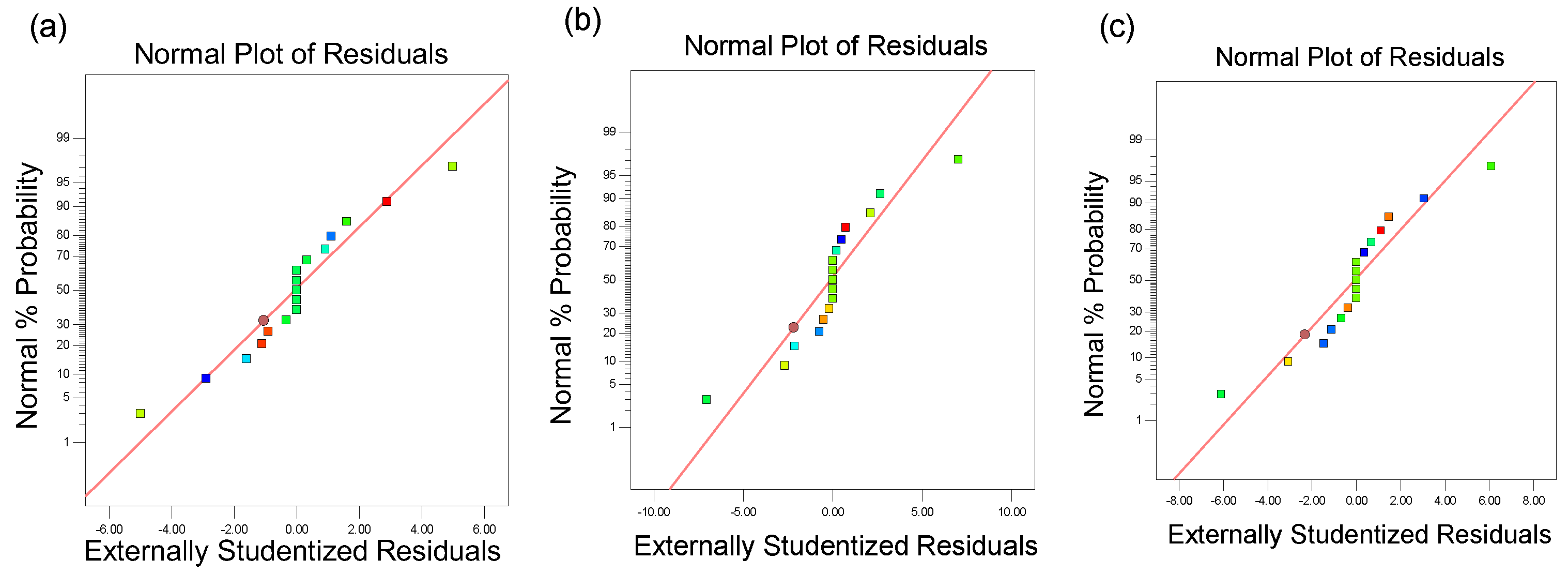
A numerical simulation was carried out to evaluate the relationship between the responses (MAP, OAR, and AS) and the parameters, inlet flow rate (IFR), rotational speed (RS), and joint angle (JA). The range of values for each factor in the response surface method is shown in Table 2. The experimental design of each parameter and the corresponding result is summarized in Table 3. The statistic model was fitted to the three responses, and the ANOVA result is listed in Table 4. The value of p is below 0.01 for the regression model, and the coefficient of determination R2 > 0.95 is close to 1. Therefore, the quadratic models for all the responses have high reliability. The results of the main diagnostic analysis are shown in Figure 2, which shows that the residuals of all three response variables obey a normal distribution.

3. Results and Discussions

3.1. Trajectory of a Single Bead Moving in the Drum

Figure 3 shows the trajectory of a single bead moving in the rotary drum dryer. In Figure 3a, the flights in the horizontal rotary drum have an inclined angle of 5°. Thus, the bead acquires an axial speed and moves toward the outlet with the rotational motion of the rotary drum. In the conventional flight with the inclined angle of 0°, as shown in Figure 3b, the bead only moves near the inlet and has no trend of axial movement.

3.2. Individual Factor Effects

The flow pattern and linear velocities of beads at different joint angles are shown in Figure 4. With the change in joint angle, the flow pattern of beads changes significantly. Between 90° and 180°, when the joint angle is small, the flight can lift the beads to the highest point of the rotary drum and then release them, and the material curtain fills the entire cross-section of the drum. As the joint angle increases, the flights’ ability to hold the fillers decreases and the material is released earlier, with the material curtain forming only on the right side of the drum.
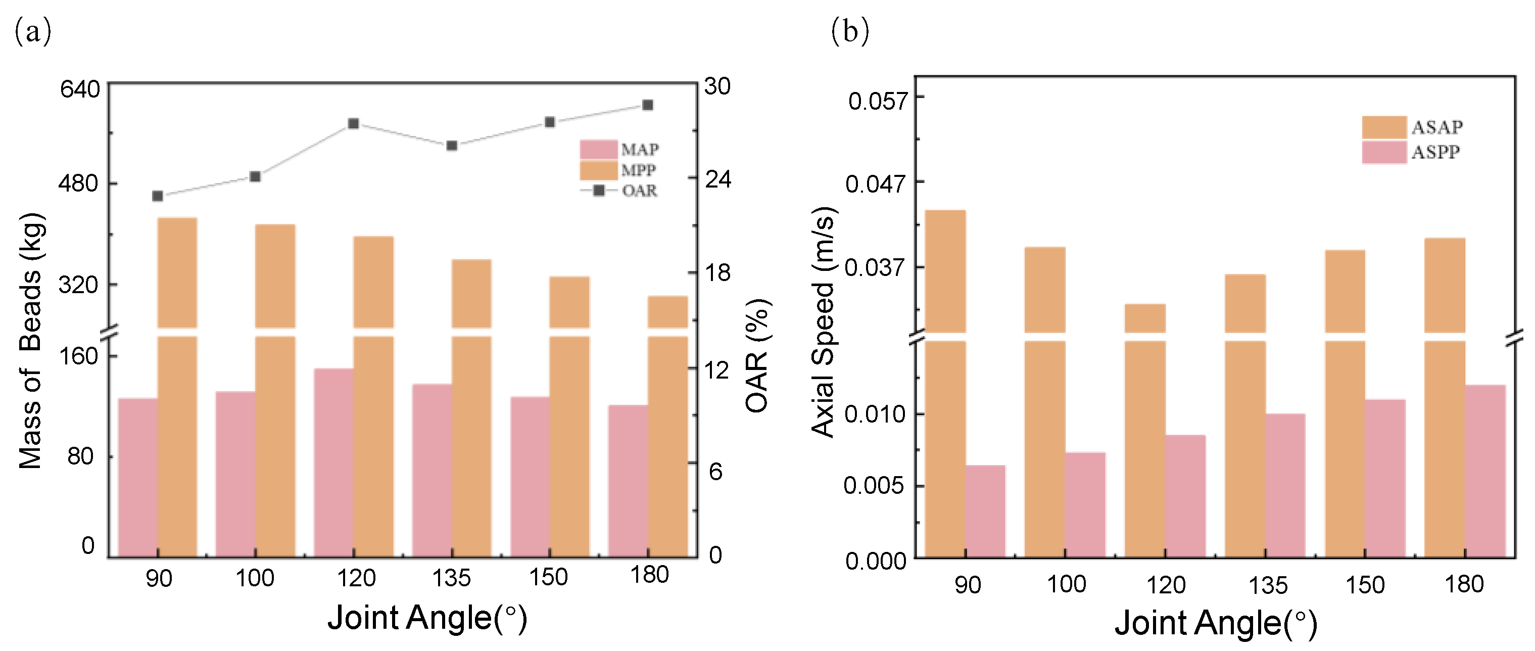
Figure 5 exhibits the dynamic behavior of beads in the rotary drum with inclined flights, including the MAP, MPP, OAR, ASAP, and ASPP values at different joint angles of flights. For the joint angle between 90° and 120°, a large number of fillers are held by the flights, the mass of fillers entering the active phase is lower, and the MAP increases with the joint angle. The MAP reaches its peak when the joint angle is 120°. When the joint angle α is above 120°, the ability of the flights to lift the fillers becomes weakened, and some of the fillers are not lifted to the highest point and fall back to the passive phase. In this stage, the MAP decreases with the increasing joint angle. For the joint angle between 90° and 180°, the MPP decreases with the joint angle. For AS, as shown in Figure 5b, the ASAP is much higher than that of the passive phase. The ASAP decreases as the joint angle increases from 90° to 120°, and then increases as the joint angle increases from 120° to 180°. The ASPP increases with the increase in the joint angles. This indicates that increasing the joint angle can facilitate the sliding of beads in the passive phase.
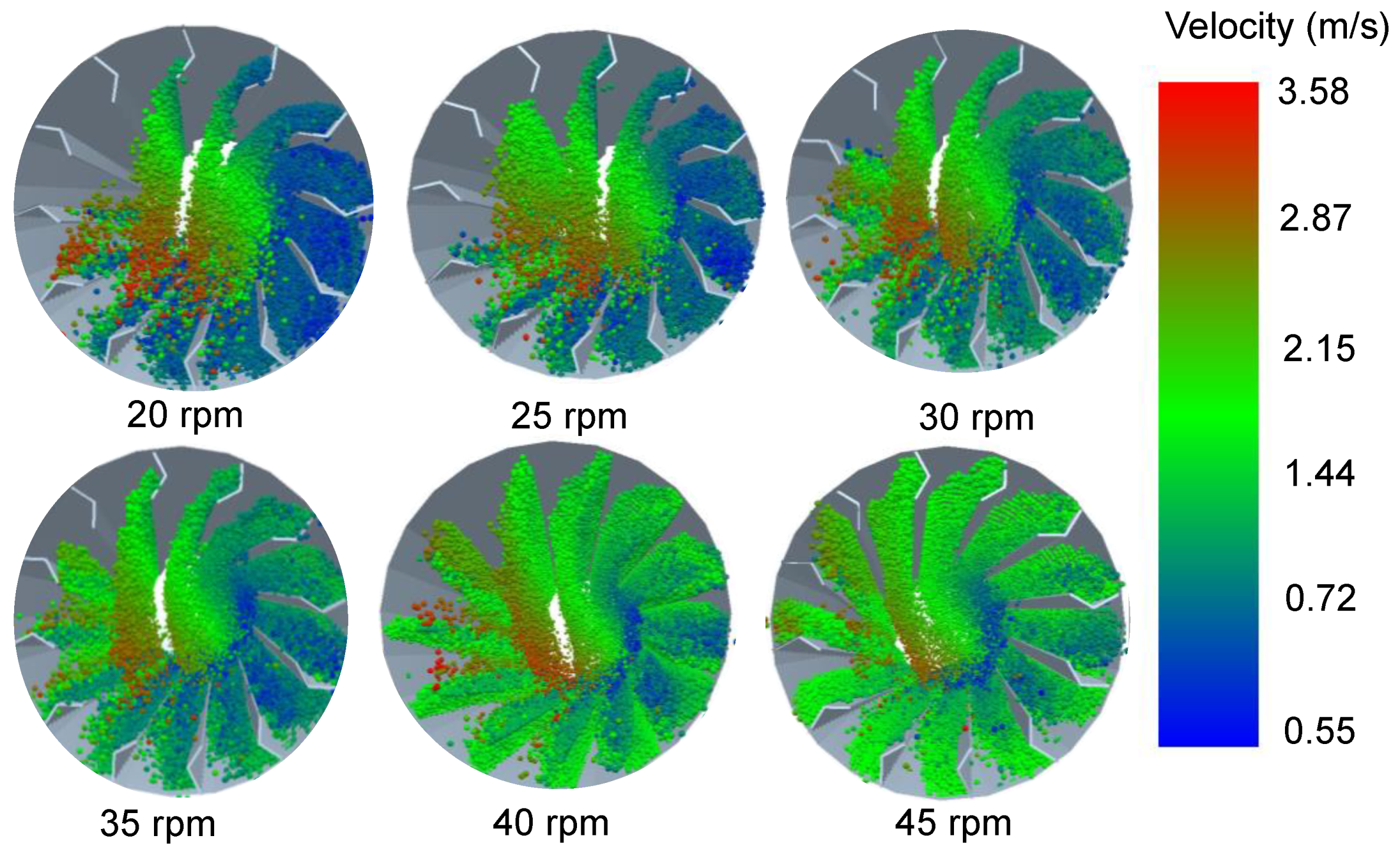
The change in the motion behavior of beads with the rotational speed is shown in Figure 6. When the rotational speed is 20 rpm, the motion behavior of beads shows a state of cascading. With the increase in the rotational speed, the motion behavior gradually changes to a state of cataracting. When the rotational speed is 40 rpm, the motion of the beads is dominated by centrifuging. Under the effect of centrifugal force, the drop point of beads is also delayed with the increase in rotational speed. Meanwhile, the linear velocity of the particles decreases because most of the fillers accumulate in the passive phase.
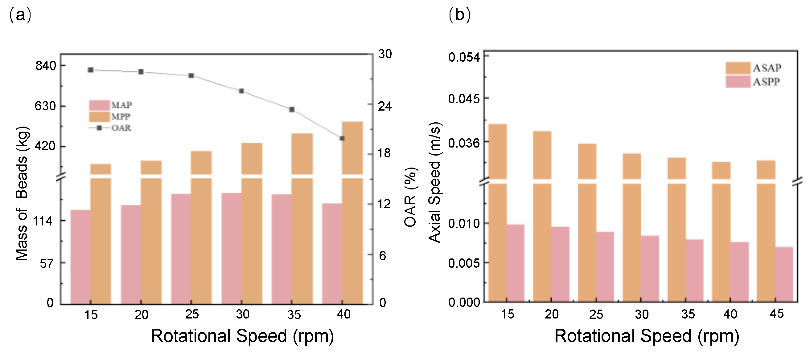
The effect of the rotational speed on the variables of MAP, MPP, OAR, ASAP, and ASPP is shown in Figure 7. When the rotational speed is in the cascading state, a large number of fillers do not enter the active phase to form a material curtain, but slide back into the passive phase when lifted by the flight. As the rotational speed increases, more and more fillers are thrown into the active phase, and the MAP value reaches a peak when the rotational speed is 35 rpm. After that, the centrifugal motion of beads is dominant and the MAP decreases gradually. With the increase in the rotational speed from 15 rpm to 45 rpm, the value of MPP increases due to the increase in the centrifugal force, and the OAR decreases due to the rapid increase in MPP. The ASAP and ASPP both decrease with increasing rotational speed. This is because the increase in centrifugal forces slows down the axial motion of the beads.
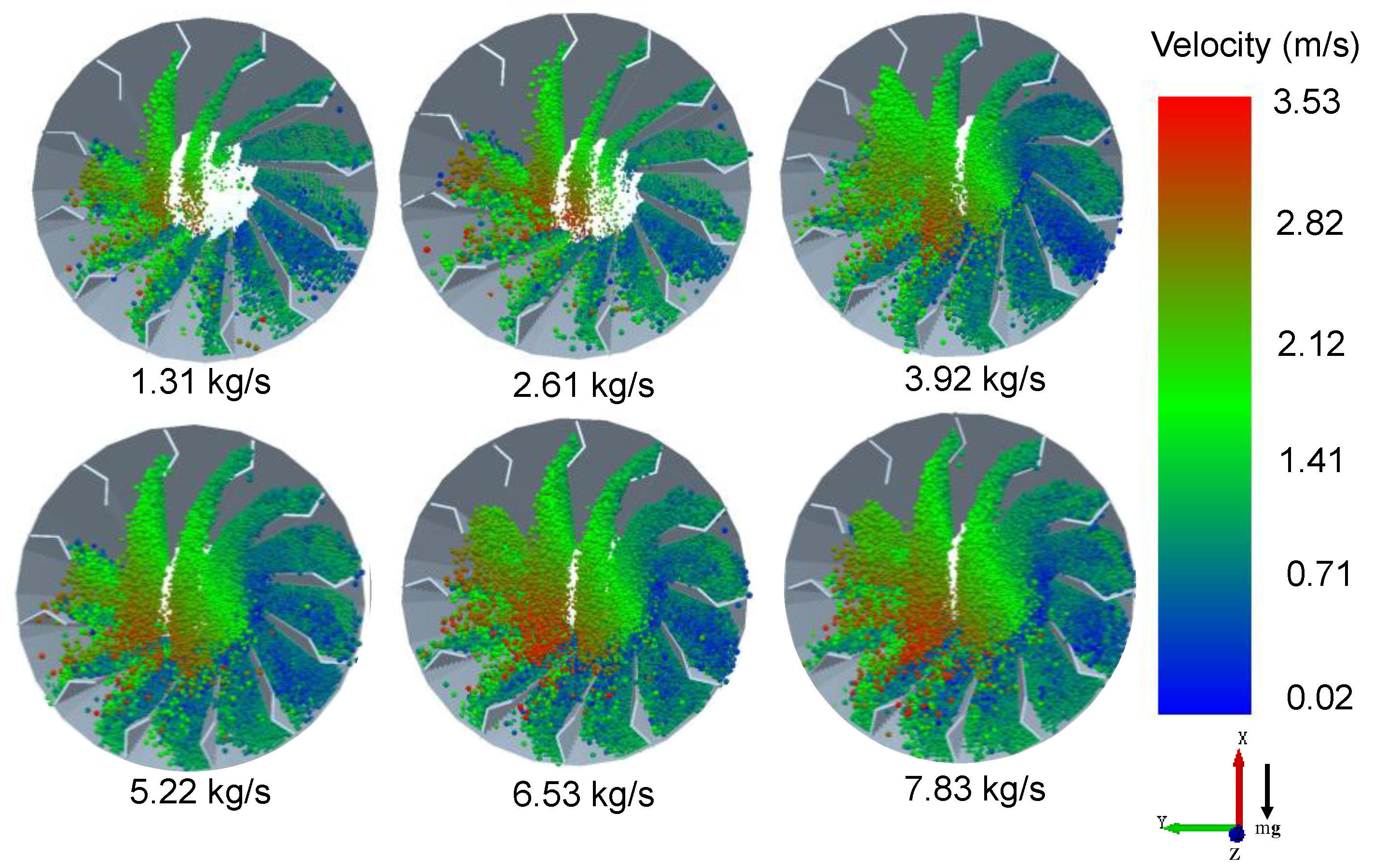
The inlet flow rate is another important factor influencing the movement of beads. Figure 8 shows the flow patterns of beads in the rotary drum with different inlet flow rates. The vertical bars show the linear velocities of the beads in the rotary drum with different inlet flow rates. The beads formed a larger material curtain in the active phase when the inlet flow rate increases. However, the unloading position remains unchanged when the inlet flow rate increases. Thus, the linear velocity of the beads does not change significantly.
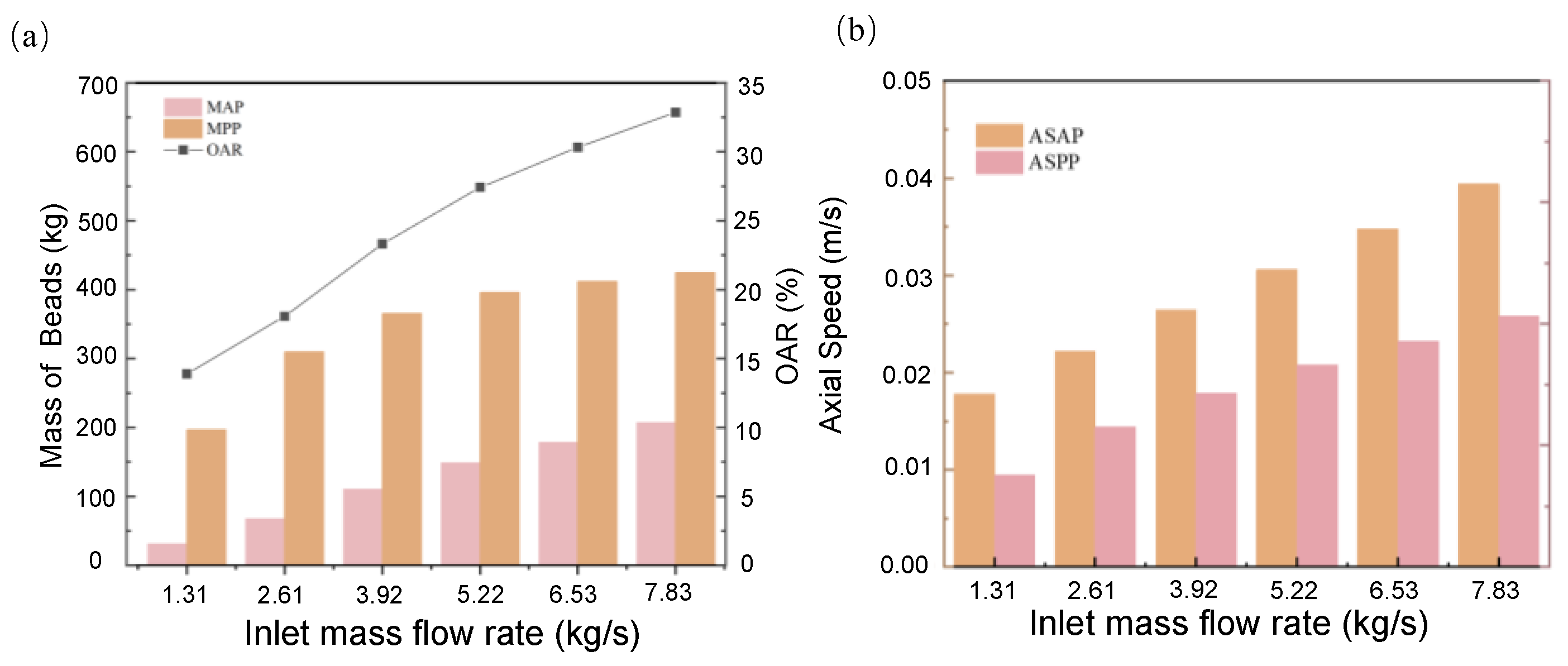
In Figure 9a, the MAP increases as the inlet flow rates keep increasing. When the inlet flow rate is small, the beads are filled in the passive phase between the flights, and only a few fillers enter the active phase, so the MAP value is small. With increments in the inlet flow rate, the drum gradually enters the “design-loading” state. When the inlet flow rate continually increases, the drum will enter the “over-loading” state. At this time, the total beads will exceed the drum’s load-bearing capacity, and thus the drying efficiency will be reduced. In Figure 9b, as the inlet flow rate increases from 1.31 kg/s to 7.83 kg/s, both the values of ASAP and ASPP increase.

3.3. Interactive Effects

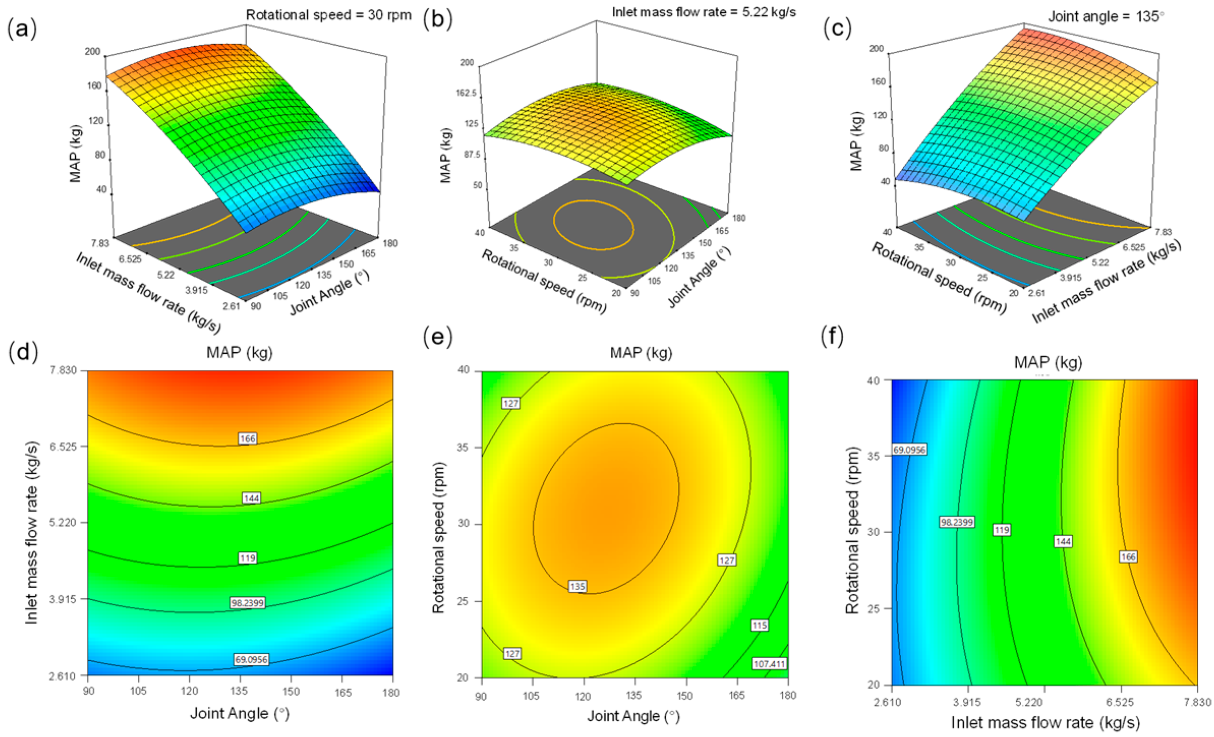
Figure 10 shows the response surface maps and contour maps of the effect of three factors on the MAP through interaction. In Figure 10a, the MAP increases and then decreases with the increase in joint angle. When the joint angle keeps unchanged, the MAP increases with the increase in inlet flow rate. The MAP reaches a maximum value when the joint angle is 139° and the inlet flow rate is 7.83 kg/s. In Figure 10b, the MAP increases and then decreases with the increase in both rotational speed and joint angle. In Figure 10c, the MAP increases with the inlet flow rate and does not change significantly with rotational speed.
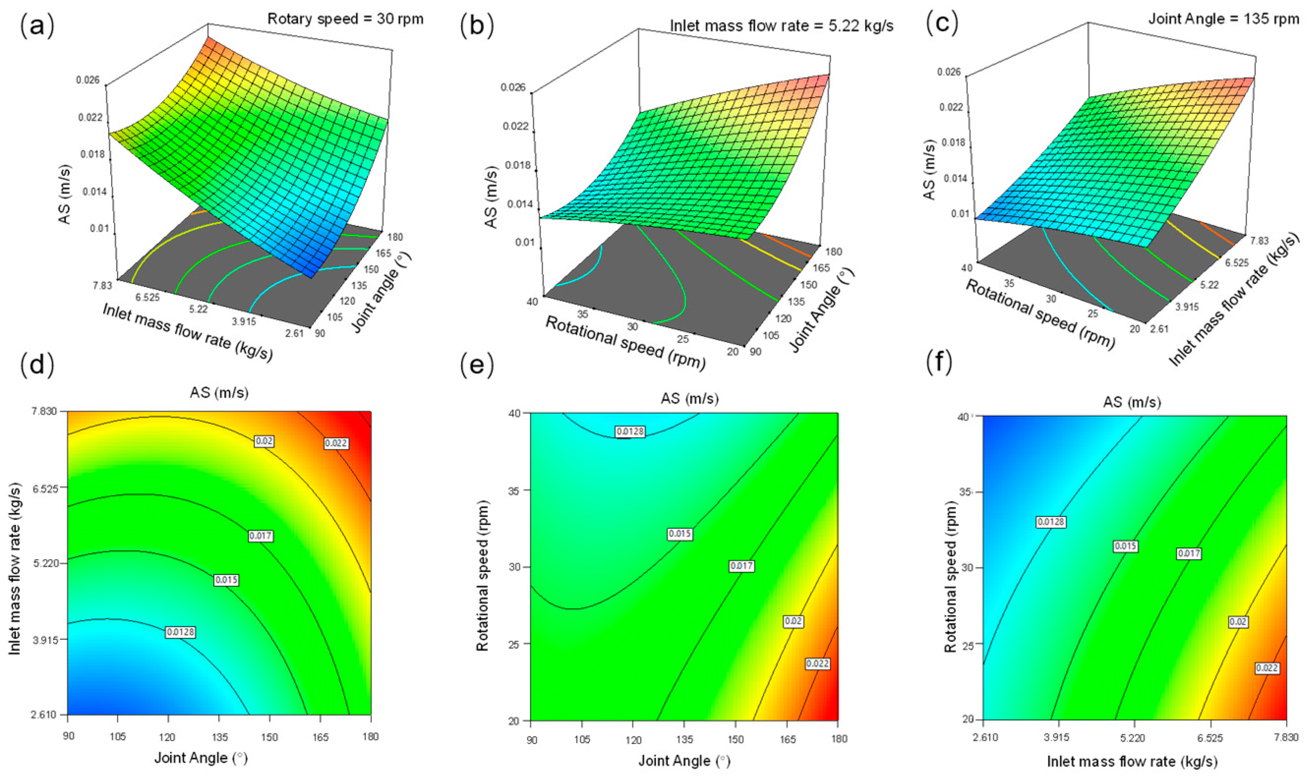
In the contour maps, if the curves show a clear oval shape, the interaction between the two parameters is obvious. Meanwhile, the curves with circular shapes suggest that the interaction between the two parameters is not significant [37]. As can be seen from Figure 10, the interactive effect of inlet flow rate and rotational speed on the MAP is the most significant. There was also some interaction between the joint angle and inlet flow rate, which had an effect on the MAP. From Figure 10b,e, it can be seen that the response surface is very smooth and the contour map is rounded, indicating that the interaction between joint angle and rotational speed is weak [38]. The maximum MAP value of 194.05 kg can be obtained by optimization with a joint angle of 139°, an inlet flow rate of 7.83 kg/s, and a drum speed of 37 rpm.
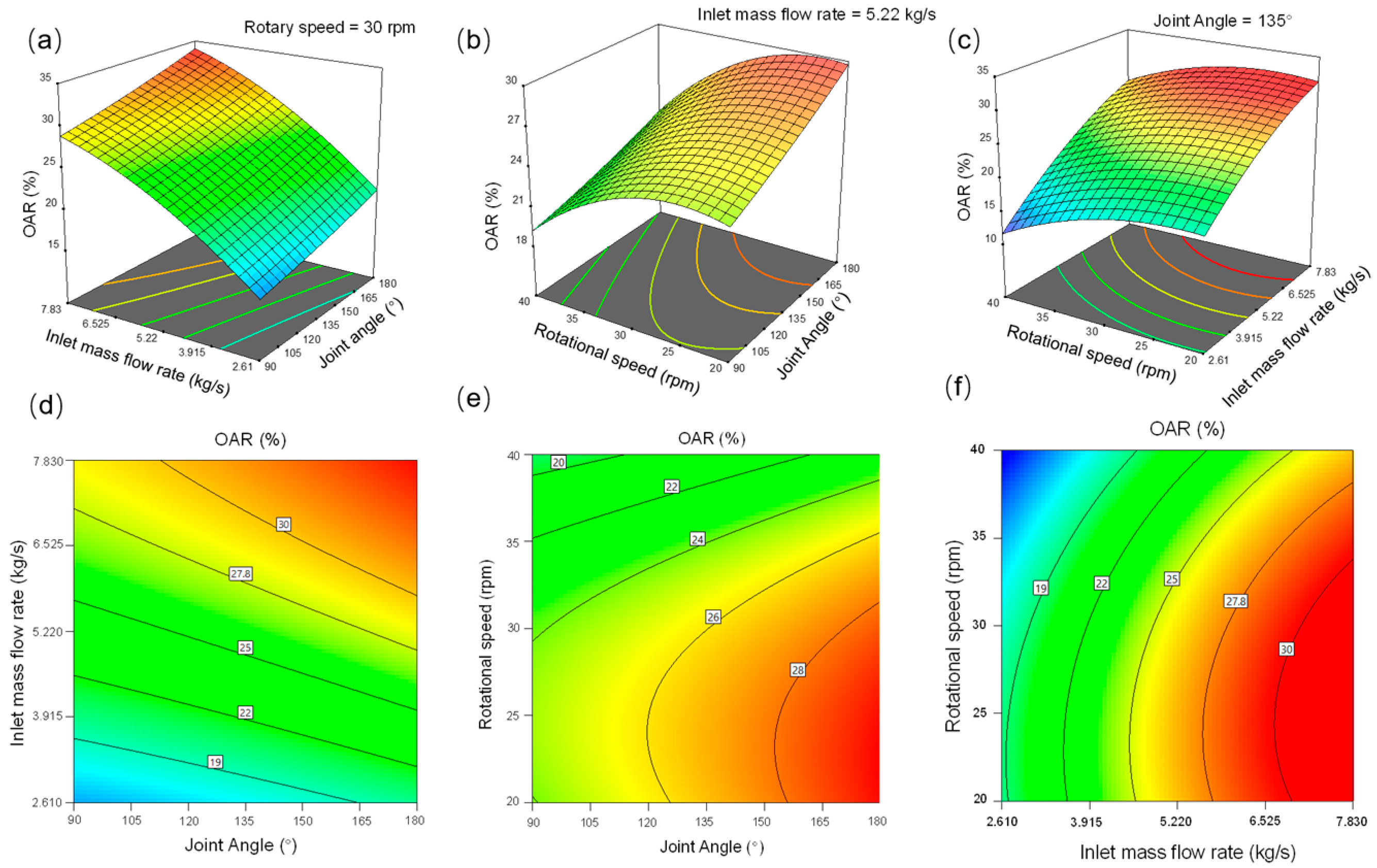
Figure 11 shows the response surface maps and contour maps of the effect of the three factors on the OAR through interaction. In Figure 11a, the OAR increases when the inlet flow rate and the joint angle increase simultaneously, and the OAR value reaches a maximum when the joint angle is 180° and the inlet flow rate is 7.83 kg/s. The decrease in the rotational speed and the increase in the joint angle, as shown in Figure 11b, contribute to an increase in the OAR value. This means that by adjusting the flight structure as well as the rotational speed, more fillers can fall into the active phase. The interaction between drum rotational speed and inlet flow rate is shown in Figure 11c. The OAR increases with the inlet flow rate and decreases with the rotational speed. In Figure 11d–f, the contour lines show curves [39], indicating that there are interactions between the parameters on the OAR.
Figure 12 shows the response surface maps and contour maps about the effects of three factors on AS through their interaction. In Figure 12a, the AS increases significantly with the increase in joint angle and inlet flow rate. In Figure 12b, AS increases with the decrease in rotational speed and the increase in joint angle. When the drum speed is 20 rpm and the joint Angle is 180°, the maximum particle axial speed is 0.024 m/s. Figure 12c shows that the AS increases with the inlet flow rate and decreases with the rotational speed, and the change is more obvious with the inlet flow rate. In Figure 12d–f, all the contour maps show curved shapes, indicating a complex interactive effect of these factors on AS. In Figure 12e, the contour map shows a saddle shape [40], indicating that the interaction of joint angle and rotational speed on AS is quite significant.

3.4. Influence of the Inclined Angles

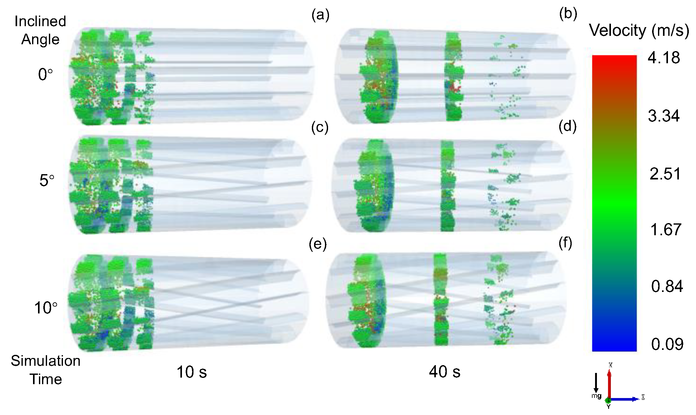
Based on the optimization of the MAP, OAR, and AS, we studied the effect of inclined flight on the axial motion of beads. Figure 13 shows a partial snapshot of the motion of the beads with different inclined angles (inclined angle = 0°, 5°, and 10°). Since there are beads continuously entering the inlet, the beads still move forward when the inclined angle is 0°. At the same time, the beads in the drum with the inclined angle advance more, indicating that the inclined angle promotes the axial movement of fillers. At 40 s, as in Figure 13b,d,e, the inclined angle clearly promotes the axial motion of the beads.
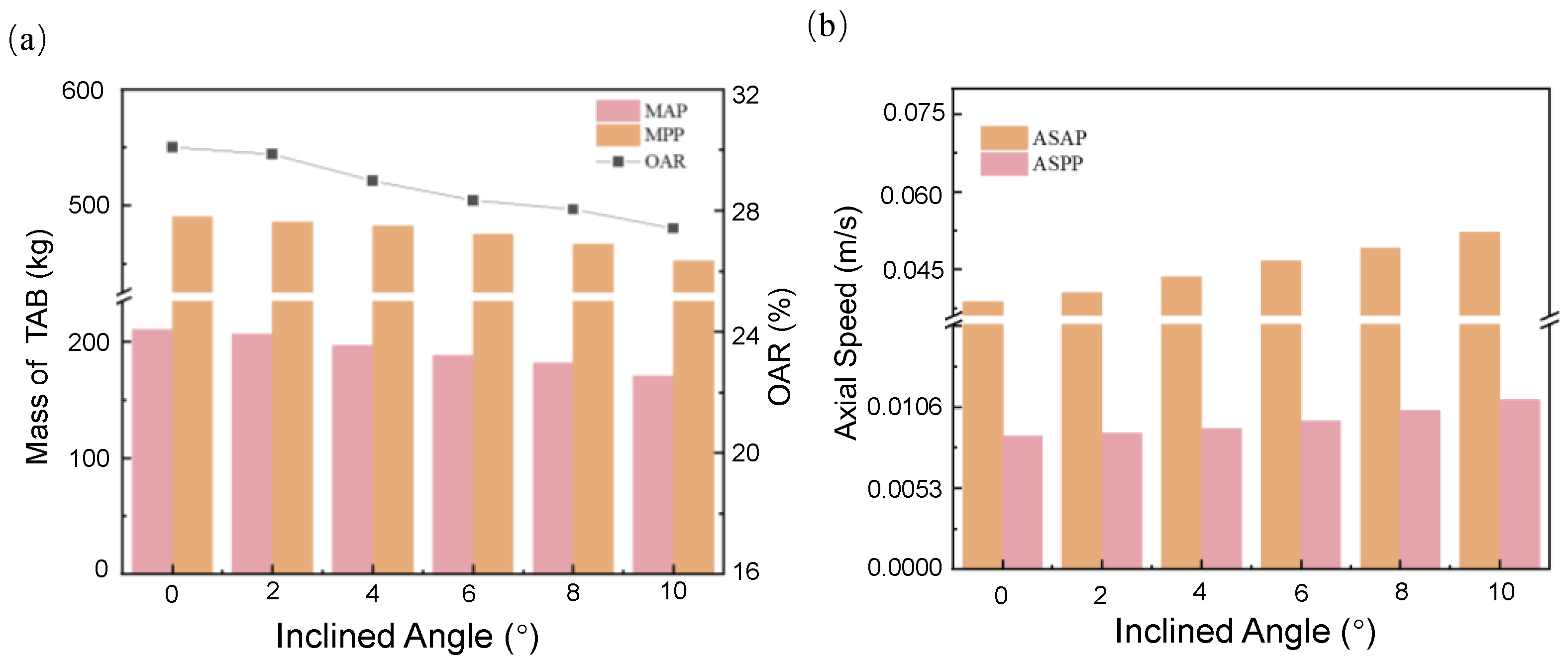
Figure 14 shows the effect of the inclined angle on the MAP, MPP, OAR, ASAP, and ASPP. The inlet flow rate is constant, and the AS is larger in the drum with inclined flights than that in the drum without inclined flights (inclined angle = 0°). As a result, the fillers accumulated in the drum with inclined flights are smaller than those in the drum without inclined flights. Additionally, the values of MAP and MPP in the drum without inclined flights are larger than those in the drum with inclined flights. As the inclined angle increases, both the MAP and MPP show a decrease. This suggests that the inclined flight can promote the axial motion of the beads. In Figure 14a, the OAR decreases with an inclined angle. As shown in Figure 14b, the axial speed of beads in the active phase is significantly higher than that in the passive phase, and the main range of axial speed is between 0.04 m/s and 0.06 m/s. This indicates that the axial motion of the particles mainly occurs in the active phase, and the inclined angle has an obvious promotion effect on the axial motion of the fillers. The speed of the TAB filler in the passive phase is between 0.009 m/s and 0.012 m/s, which indicates that the axial motion of the filler in the passive stage is not obvious. Compared with when the inclined angle is 0°, the active phase axial speed is enhanced by 26% when the inclined angle is 10°.

4. Conclusions

In this paper, a new type of horizontal rotary drum dryer with inclined flights and beads was designed. DEM simulation combined with RSM was used to study the effects of joint angle, inlet flow rate, and rotational speed on the motion of beads in the active and passive phases. The results show that the MAP tends to increase and then decrease as the joint angle increases. This is due to the different holding capacities of the beads and the different discharge points of the beads at different flight joint angles. With the increase in the rotational speed, the motion state of the beads changes from cascading to centrifuging, which leads to a change in the bead discharge points, so the MAP tends to increase and then decrease. As the inlet flow rate increases, the number of beads entering the active phase continues to increase, resulting in a continuous increase in MAP. The OAR decreases with the rotational speed and increases with the inlet flow rate. The AS decreases with the rotational speed and increases with the joint angle and inlet flow rate. The optimized configuration and operating conditions of the rotary drum are obtained when the MAP value reaches the maximum (rotational speed = 37 rpm, joint angle = 139° and inlet flow rate = 7.83 kg/s). The interaction between rotational speed and inlet flow rate is the most significant for MAP. The joint angle and inlet flow rate have a significant interactive effect on AS. Additionally, the rotational speed, joint angle and inlet flow rate show an interactive effect on OAR and AS. The inclined angle makes a significant contribution to the axial motion of fillers. The axial speed is mainly provided by the active phase. As the inclined angle increases, the axial speed of the beads also increases. Further studies could focus on the heat transfer and energy efficiency of drums with inclined flights and beads.

Author Contributions

Conceptualization, L.X. and S.X.; methodology, L.X. and X.Z; software, X.Z.; validation, X.Z. and W.Z.; formal analysis, L.X. and W.Z.; investigation, X.Z.; resources, L.X.; data curation, X.Z.; writing—original draft preparation, X.Z.; writing—review and editing, X.Z., W.Z. and L.X.; visualization, S.X.; supervision, S.X.; project administration, L.X.; funding acquisition, L.X. All authors have read and agreed to the published version of the manuscript.

Funding

This research was funded by the Central Guidance on Local Science and Technology Development Foundation of Hebei Province of China, grant number 226Z3101G.

Data Availability Statement

Not applicable.

Conflicts of Interest

The authors declare no conflict of interest.

Nomenclature

List of symbols
ecoefficient of restitution (−)
Fforce [N]
ggravity [m s−2]
Gshear modulus [Pa]
G* equivalent shear modulus [Pa]
Imoment of inertia [m s−2]
kelastic constant [kg m−2]
Mrolling friction torque [N m−1]
mparticle mass [kg]
m* equivalent mass [kg]
Rradius [m]
R* radius [m]
Sstiffness [Pa m]
Ttangential torque [N m−1]
YYoung′s modulus [Pa]
Y* equivalent Young′s modulus [Pa]
Greek symbols
αjoint angle of the two-segment flights [°]
βinclined angle between flights and wall [°]
ηPoisson’s ratio [−]
δoverlap distance of two particles [m]
γviscoelastic damping constant [−]
μxcoefficient static friction
vparticle velocity [m/s]
ωrotational speed [rpm]
Indices
i and jparticle identification index
nnormal direction
ttangential direction

References

  1. Trojosky, M. Rotary drums for efficient drying and cooling. Dry. Technol. 2019, 37, 632–651. [Google Scholar] [CrossRef]
  2. Yang, S.; Sun, Y.; Chew, J.W. Simulation of the granular flow of cylindrical particles in the rotating drum. AIChE J. 2018, 64, 3835–3848. [Google Scholar] [CrossRef]
  3. Yazdani, E.; Hashemabadi, S.H. DEM simulation of heat transfer of binary-sized particles in a horizontal rotating drum. Granul. Matter 2018, 21, 6. [Google Scholar] [CrossRef]
  4. Sunkara, K.R.; Herz, F.; Specht, E.; Mellmann, J. Transverse flow at the flight surface in flighted rotary drum. Powder Technol. 2015, 275, 161–171. [Google Scholar] [CrossRef]
  5. Lee, A.; Sheehan, M.E. Development of a geometric flight unloading model for flighted rotary dryers. Powder Technol. 2010, 198, 395–403. [Google Scholar] [CrossRef]
  6. Sunkara, K.R.; Herz, F.; Specht, E.; Mellmann, J. Influence of flight design on the particle distribution of a flighted rotating drum. Chem. Eng. Sci. 2013, 90, 101–109. [Google Scholar] [CrossRef]
  7. Heilbuth, R.R.; Souza, G.M.; Santos, D.A.; Brandao, R.J.; Barrozo, M.A.S.; Duarte, C.R. Numerical evaluation of the granular mixing behavior in a flighted rotary drum through the Discrete Element Method. Powder Technol. 2022, 400, 117251. [Google Scholar] [CrossRef]
  8. Piton, M.; Huchet, F.; Le Corre, O.; Le Guen, L.; Cazacliu, B. A coupled thermal-granular model in flights rotary kiln: Industrial validation and process design. Appl. Therm. Eng. 2015, 75, 1011–1021. [Google Scholar] [CrossRef]
  9. Xie, Q.; Chen, Z.; Hou, Q.; Yu, A.B.; Yang, R. DEM investigation of heat transfer in a drum mixer with lifters. Powder Technol. 2017, 314, 175–181. [Google Scholar] [CrossRef]
  10. Seidenbecher, J.; Herz, F.; Sunkara, K.R.; Mellmann, J. Modelling the final discharge angle in flighted rotary drums. Granul. Matter 2022, 24, 123. [Google Scholar] [CrossRef]
  11. Nascimento, S.M.; Lima, R.M.; Brandão, R.J.; Duarte, C.R.; Barrozo, M.A.S. Eulerian study of flights discharge in a rotating drum. Can. J. Chem. Eng. 2019, 97, 477–484. [Google Scholar] [CrossRef]
  12. Geng, F.; Li, Y.; Wang, X.; Yuan, Z.; Yan, Y.; Luo, D. Simulation of dynamic processes on flexible filamentous particles in the transverse section of a rotary dryer and its comparison with ideo-imaging experiments. Powder Technol. 2011, 207, 175–182. [Google Scholar] [CrossRef]
  13. Pan, J.P.; Wang, T.-J.; Yao, J.-J.; Jin, Y. Granule transport and mean residence time in horizontal drum with inclined flights. Powder Technol. 2006, 162, 50–58. [Google Scholar] [CrossRef]
  14. Karali, M.A.; Sunkara, K.R.; Herz, F.; Specht, E. Experimental analysis of a flighted rotary drum to assess the optimum loading. Chem. Eng. Sci. 2015, 138, 772–779. [Google Scholar] [CrossRef]
  15. Seidenbecher, J.; Herz, F.; Meitzner, C.; Specht, E.; Wirtz, S.; Scherer, V.; Liu, X. Experimental analysis of the flight design effect on the temperature distribution in rotary kilns. Chem. Eng. Sci. 2021, 240, 116652. [Google Scholar] [CrossRef]
  16. Bongo Njeng, A.S.; Vitu, S.; Clausse, M.; Dirion, J.L.; Debacq, M. Effect of lifter shape and operating parameters on the flow of materials in a pilot rotary kiln: Part II. Experimental hold-up and mean residence time modeling. Powder Technol. 2015, 269, 566–576. [Google Scholar] [CrossRef]
  17. Yang, S.; Cahyadi, A.; Wang, J.; Chew, J.W. DEM study of granular flow characteristics in the active and passive regions of a three-dimensional rotating drum. AIChE J. 2016, 62, 3874–3888. [Google Scholar] [CrossRef]
  18. Yu, M.; Zhang, H.; Guo, J.; Zhang, J.; Han, Y. Three-dimensional DEM simulation of polydisperse particle flow in rolling mode rotating drum. Powder Technol. 2022, 396, 626–636. [Google Scholar] [CrossRef]
  19. Yazdani, E.; Hassan Hashemabadi, S. Three-dimensional heat transfer in a particulate bed in a rotary drum studied via the discrete element method. Particuology 2020, 51, 155–162. [Google Scholar] [CrossRef]
  20. Zhang, L.; Jiang, Z.; Mellmann, J.; Weigler, F.; Herz, F.; Bück, A.; Tsotsas, E. Influence of the number of flights on the dilute phase ratio in flighted rotating drums by PTV measurements and DEM simulations. Particuology 2021, 56, 171–182. [Google Scholar] [CrossRef]
  21. Silveira, J.C.; Lima, R.M.; Brandao, R.J.; Duarte, C.R.; Barrozo, M.A.S. A study of the design and arrangement of flights in a rotary drum. Powder Technol. 2022, 395, 195–206. [Google Scholar] [CrossRef]
  22. Bongo Njeng, A.S.; Vitu, S.; Clausse, M.; Dirion, J.L.; Debacq, M. Effect of lifter shape and operating parameters on the flow of materials in a pilot rotary kiln: Part I. Experimental RTD and axial dispersion study. Powder Technol. 2015, 269, 554–565. [Google Scholar] [CrossRef]
  23. Xie, L.; Yang, L.; Su, L.; Xu, S.; Zhang, W. A Novel Rotary Dryer Filled with Alumina Ceramic Beads for the Treatment of Industrial Wastewaters: Numerical Simulation and Experimental Study. Processes 2021, 9, 862. [Google Scholar] [CrossRef]
  24. Xie, L.X.; Xu, S.C.; Su, L.B.; Cao, C.P.; Du, H.X.; Yang, L.L. A High Efficiency and Energy Saving Evaporative Drying Device. Chinese Patent CN211310913U, 21 August 2020. [Google Scholar]
  25. Zuo, Z.; Gong, S.; Xie, G.; Zhang, J. Sensitivity analysis of process parameters for granular mixing in an intensive mixer using response surface methodology. Powder Technol. 2021, 384, 51–61. [Google Scholar] [CrossRef]
  26. Rong, W.; Feng, Y.; Schwarz, P.; Yurata, T.; Witt, P.; Li, B.; Song, T.; Zhou, J. Sensitivity analysis of particle contact parameters for DEM simulation in a rotating drum using response surface methodology. Powder Technol. 2020, 362, 604–614. [Google Scholar] [CrossRef]
  27. Karatza, Z.; Andò, E.; Papanicolopulos, S.A.; Viggiani, G.; Ooi, J.Y. Effect of particle morphology and contacts on particle breakage in a granular assembly studied using X-ray tomography. Granul. Matter 2019, 21, 44. [Google Scholar] [CrossRef]
  28. Yin, Z.Y.; Wang, P.; Zhang, F. Effect of particle shape on the progressive failure of shield tunnel face in granular soils by coupled FDM-DEM method. Tunn. Undergr. Space Technol. 2020, 100, 103394. [Google Scholar] [CrossRef]
  29. Wang, P.; Yin, Z.Y.; Wang, Z.Y. Micromechanical Investigation of Particle-Size Effect of Granular Materials in Biaxial Test with the Role of Particle Breakage. J. Eng. Mech. 2022, 148, 04021133. [Google Scholar] [CrossRef]
  30. Yang, X.; Long, L.H.; Matthew, T. Effect of particle shape on stress-dilatancy responses of medium-dense sands. J. Geotech. Geoenvironmental Eng. 2019, 145, 04018105. [Google Scholar]
  31. Cundall, P.A.; Strack, O.D.L. A discrete numerical model for granular assemblies. Géotechnique 1979, 29, 47–65. [Google Scholar] [CrossRef]
  32. Silveira, J.C.; Brandao, R.J.; Lima, R.M.; Machado, M.V.C.; Barrozo, M.A.S.; Duarte, C.R. A fluid dynamic study of the active phase behavior in a rotary drum with flights of two and three segments. Powder Technol. 2020, 368, 297–307. [Google Scholar] [CrossRef]
  33. Stevens, A.B.; Hrenya, C.M. Comparison of soft-sphere models to measurements of collision properties during normal impacts. Powder Technol. 2005, 154, 99–109. [Google Scholar] [CrossRef]
  34. Ma, H.; Zhao, Y. Modelling of the flow of ellipsoidal particles in a horizontal rotating drum based on DEM simulation. Chem. Eng. Sci. 2017, 172, 636–651. [Google Scholar] [CrossRef]
  35. Santos, D.A.; Dadalto, F.O.; Scatena, R.; Duarte, C.R.; Barrozo, M.A.S. A hydrodynamic analysis of a rotating drum operating in the rolling regime. Chem. Eng. Res. Des. 2015, 94, 204–212. [Google Scholar] [CrossRef]
  36. Zheng, X.; Jin, B.; Zhang, Y.; Zhang, Y.; Zhou, C. Numerical Simulation of Flow Characteristics in an Inclining Rotating Kiln with Continuous Feeding. Int. J. Chem. React. Eng. 2019, 17. [Google Scholar] [CrossRef]
  37. Chen, L.J.; Sun, Z.J.; Zhang, Y. Energy loss caused by the elbow of stiff shotcrete pneumatic conveying based on response surface method and CFD-DEM. Powder Technol. 2022, 408, 117726. [Google Scholar] [CrossRef]
  38. Luo, D. Optimization of total polysaccharide extraction from Dioscorea nipponica Makino using response surface methodology and uniform design. Carbohydr. Polym. 2012, 90, 284–288. [Google Scholar] [CrossRef]
  39. Shasha, H.U.; Yihong, W.; Chengming, W.; Moucheng, W.U. Optimization of Extraction Process of Water-soluble Polysaccharides from Seeds of Pistacia chinensis Bung by Response Surface Methodology. Food Sci. 2008, 29, 172–176. [Google Scholar]
  40. Murthy, M.S.R.C.; Swaminathan, T.; Rakshit, S.K. Statistical optimization of lipase catalyzed hydrolysis of methyloleate by response surface methodology. Bioprocess Eng. 2000, 22, 35–39. [Google Scholar] [CrossRef]
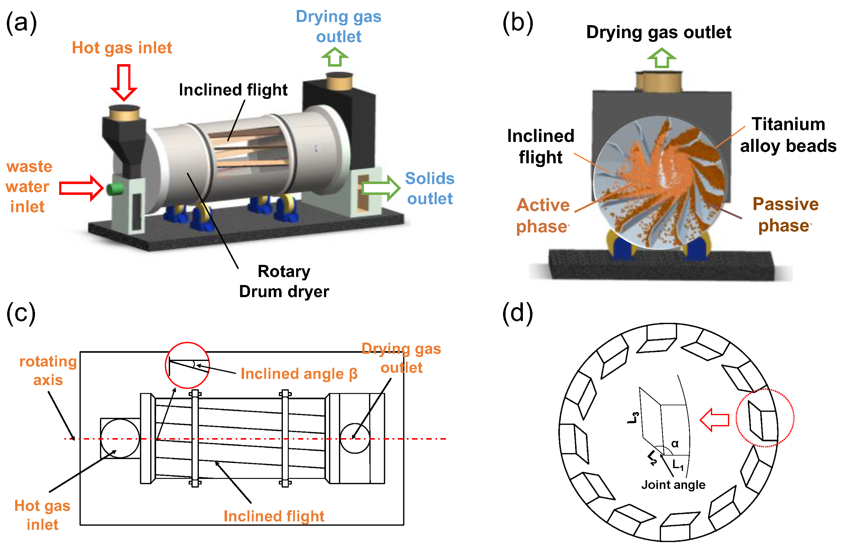
Figure 1. Schematic of a horizontal rotary drum with inclined flights (a), schematic of the cross-section (b), diagram of the top view (c) and the cross-section (d).
Processes 11 01363 g001
Figure 2. Normal plot of residuals for (a) MAP, (b) OAR; (c) AS.
Processes 11 01363 g002
Figure 3. Trajectory of a single bead moving in a rotary drum dryer with inclined flights of (a) 5° inclined angle and (b) 0° inclined angle (rotational speed: 20 rpm, joint angle: 180°).
Processes 11 01363 g003
Figure 4. The motion behavior of beads with different joint angle. (rotational speed: 35 rpm, inlet flow rate: 5.22 kg/s, inclined angle: 5°).
Processes 11 01363 g004
Figure 5. Dynamic behavior of beads with different joint angles: (a) MAP, MPP and OAR, (b) axial speed in active phase (ASAP) and passive phase (ASPP). (rotational speed: 35 rpm, inlet flow rate: 5.22 kg/s, and inclined angle: 5°).
Processes 11 01363 g005
Figure 6. The motion behavior of beads with different rotational speeds. (joint angle: 120°, inlet flow rate: 5.22 kg/s, and inclined angle: 5°).
Processes 11 01363 g006
Figure 7. Dynamic behavior of beads with different rotational speed: (a) MAP, MPP and OAR, (b) axial speed in active phase (ASAP) and passive phase (ASPP). (joint angle: 120°, inlet flow rate: 5.22 kg/s, and inclined angle: 5°).
Processes 11 01363 g007
Figure 8. The motion behavior of beads with different inlet flow rate. (joint angle: 120°, inlet flow rate: 5.22 kg/s, and inclined angle: 5°).
Processes 11 01363 g008
Figure 9. Dynamic behavior of beads with different inlet flow rates. (a) MAP, MPP and OAR, (b) axial speed in active phase (ASAP) and passive phase (ASPP). (joint angle: 120°, rotational speed: 35 rpm, and inclined angle: 5°).
Processes 11 01363 g009
Figure 10. Response surface of MAP with the factors of (a) joint angle and inlet flow rate, (b) joint angle and rotational speed, and (c) inlet flow rate and rotational speed. Contour map of MAP with the factors of (d) joint angle and inlet flow rate, (e) joint angle and rotational speed, and (f) inlet flow rate and rotational speed.
Processes 11 01363 g010
Figure 11. Response surface of OAR with the factors of (a) joint angle and inlet flow rate, (b) joint angle and rotational speed, and (c) inlet flow rate and rotational speed. Contour maps of OAR with the factors of (d) joint angle and mass flow rate, (e) joint angle and rotational speed, and (f) inlet flow rate and rotational speed.
Processes 11 01363 g011
Figure 12. Response surface of AS with the factors of (a) joint angle and inlet flow rate, (b) joint angle and rotational speed, and (c) inlet flow rate and rotational speed. Contour maps of AS with the factors of (d) joint angle and mass flow rate, (e) joint angle and rotational speed, and (f) inlet flow rate and rotational speed.
Processes 11 01363 g012
Figure 13. The motion behavior of beads with different inclined angles at different times. (a,c,e): the motion behavior of the beads at 10 s with inclined angles of 0°, 5°, and 10°. (b,d,f): The motion behavior of the beads at 40 s with inclined angles of 0°, 5°, and 10°. (rotational speed: 37 rpm, inlet flow rate: 7.82 kg/s, joint angle: 139°).
Processes 11 01363 g013
Figure 14. Dynamic behavior of beads with different inclined angles: (a) MAP, MPP and OA, (b) axial speed in active phase (ASAP) and passive phase (ASPP). (rotational speed: 37 rpm, inlet flow rate: 7.82 kg/s, joint angle: 139°).
Processes 11 01363 g014
Table 1. Parameters used in the DEM simulations.
PropertiesValue
Density of particle, ρ (kg/m3)4540
Young′s modulus, Y (Pa)1.2 × 10⁸
Poisson’s ratio, η (−)0.32
Restitution coefficient (particle/particle), epp (−)0.2
Restitution coefficient (particle/wall), epw (−)0.9
Coefficient static friction (particle/particle), μs,pp (−)0.54
Coefficient static friction (particle/wall), μs,pw (−)0.5
Drum diameter × Length, D × L (mm × mm)800 × 1700
Number of flights (−)12
Flights thickness, FT (mm)6
Particle diameter, Dp (mm)13
Table 2. Factors and levels for response surface design.
ParametersJoint Angle
(°)
Inlet Flow Rate (kg/s)Rotational Speed
(rpm)
Low level902.6120
Middle level1355.2230
High level1807.8340
Table 3. Experimental design values and results.
RunJoint Angle (°)Mass Flow Rate (kg/s)Rotational Speed (rpm)MAP (kg)OAR (%)AS (m/s)
1902.613058.1015.130.0107
2907.8330176.9328.000.0198
3905.2240116.6119.310.0138
4905.2220128.7825.080.0159
51355.2230137.0525.980.0155
61352.614053.4011.950.0089
71355.2230137.0525.980.0155
81357.8340196.0127.440.0175
91357.8320161.4031.000.0247
101355.2230137.0525.980.0155
111355.2230137.0525.980.0155
121355.2230137.0525.980.0155
131352.612060.6817.850.0124
141805.2220111.5021.750.0162
151807.8340178.4034.360.0239
161802.613044.1220.790.0194
171805.2230103.8029.650.0236
Table 4. ANOVA results.
ResponseFit ModelSourceSum of SquaresdfMean SquaresF-Valuep-Value
MAPQuadraticModel33,314.6993701.63146.40<0.0001
A-A226.851226.858.970.0201
B-B30,806.58130,806.581218.39<0.0001
C-C65.32165.322.580.1520
AB59.68159.682.360.1684
AC98.70198.703.900.0887
BC438.691438.6917.350.0042
A2677.111677.1126.780.0013
B2419.481419.4816.590.0047
C2356.091356.0914.080.0071
Residual176.99725.28
Cor Total33,491.6816
OARQuadraticModel528.92958.7769.05<0.0001
A-A45.27145.2753.180.0002
B-B379.231379.23445.55<0.0001
C-C66.87166.8778.57<0.0001
AB0.1210.120.140.7157
AC1.1311.131.330.2862
BC1.3711.371.610.2453
A20.2410.240.280.6118
B211.45111.4513.450.0080
C221.72121.7225.520.0015
Residual5.9670.85
Cor Total534.8816
ASQuadraticModel3.05 × 10−493.39 × 10−530.61<0.0001
A-A6.56 × 10−516.56 × 10−559.190.0001
B-B1.49 × 10−411.49 × 10−4134.34<0.0001
C-C5.10 × 10−515.10 × 10−546.050.0003
AB5.29 × 10−615.29 × 10−64.780.0651
AC7.02 × 10−617.02 × 10−66.340.0399
BC3.42 × 10−613.42 × 10−63.090.1222
A22.08 × 10−512.08 × 10−518.820.0034
B22.21 × 10−612.21 × 10−62.000.2004
C25.16 × 10−715.16 × 10−70.470.5169
Residual7.75 × 10−671.11 × 10⁻⁶
Cor Total3.13 × 10−416
Disclaimer/Publisher’s Note: The statements, opinions and data contained in all publications are solely those of the individual author(s) and contributor(s) and not of MDPI and/or the editor(s). MDPI and/or the editor(s) disclaim responsibility for any injury to people or property resulting from any ideas, methods, instructions or products referred to in the content.