Article

Comprehensive Experimental and Numerical Optimization of Diesel Engine Thermal Management Strategy for Emission Clarification and Carbon Dioxide Control

1
School of Energy and Power Engineering, Shandong University, Jinan 250061, China
2
School of Aeronautic Science and Engineering, Beihang University, Beijing 100191, China
*
Authors to whom correspondence should be addressed.
Processes 2023, 11(4), 1252; https://doi.org/10.3390/pr11041252
Submission received: 20 March 2023 / Revised: 10 April 2023 / Accepted: 12 April 2023 / Published: 18 April 2023
(This article belongs to the Special Issue Application of Heat Recovery Systems in Energy)

Abstract

:
Improving the thermal efficiency of truck diesel engines requires comprehensive optimization of the engine, exhaust aftertreatment (EAT), and possible waste heat recovery (WHR). Lower exhaust temperature at mid and low working points has caused difficulty in both emission clarification and heat recovery, which requires thermal management. Based on the diesel engine bench test and separate bench tests, this paper focuses on the thermal management strategy optimization, to increase the exhaust temperature at lower working points and optimize the thermal efficiency of the whole system. The test and numerical analysis showed that as exhaust temperature increased from 200~250 °C to 300~350 °C, soot passive regeneration reactions were enhanced, nitrogen oxide emission decreased, and energy recovery was improved. Moderate throttle valve adjustment coupled with early post injection could effectively achieve the required temperature increase. The optimized thermal management strategy increased the fuel consumption rate by no more than 1%. Meanwhile, the WHR system output increased significantly, by 62.55% at a certain mid–low working point. System CO2 emission decreased by an average of 5.4% at selected working points.

1. Introduction

The three-step approach adopted by the European Union to regulate CO2 emissions from heavy-duty vehicles [1] has further restricted the thermal efficiency of diesel engines. The already-strict emission regulations coupled with considerations in system thermal efficiency, the emission clarification process requires further optimization. The Organic Rankine cycle (ORC) system is an efficient method for waste heat recovery (WHR) in road vehicles. For truck diesel engines, more than half of the energy is taken away by engine exhaust, coolant, and charge air intercooler [2]. The high-temperature exhaust is ideal for ORC systems to achieve proper recovery. The energy quality of engine exhaust is affected by both CO2 emission regulation and Particulate Matter (PM) emission regulation [3].
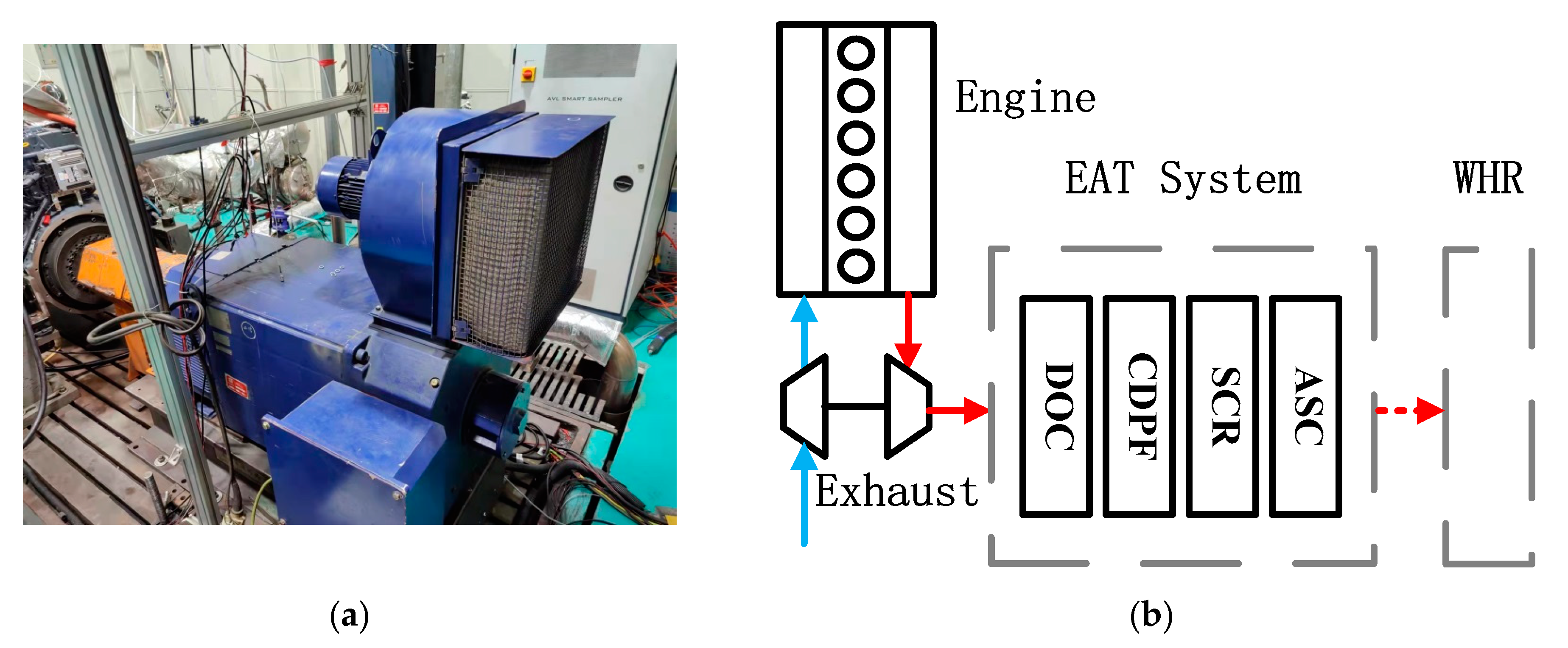
The clarification of PM requires exhaust aftertreatment (EAT), especially a Diesel Particulate Filter (DPF) for PM filtering and clarification, coupled with a Diesel Oxidation Catalyst (DOC) for related exhaust thermal management. The PM clarification process within the DPF regeneration process requires thermal management, as a significantly higher temperature is required for active regeneration. During active regeneration, diesel fuel is injected before the DOC through a separate injector [4], or post injection [5], and oxidized in the DOC to increase the exhaust temperature to above 450 °C and even more than 600 °C; the high-temperature exhaust will then rapidly oxidize the PM accumulated in the DPF [6]. Active regeneration achieved PM clarification at the cost of increased CO2 emission, as fuel oxidized within the DOC will not generate power output. Passive regeneration largely focused on the reaction between nitrogen oxides (NOx) and PM and activates at a much lower exhaust temperature, thus requiring no rapid exhaust temperature increase [7].
The thermal management during the PM clarification process was largely focused on active regeneration, as a rapid temperature increase is required for activation. Bai et al. [
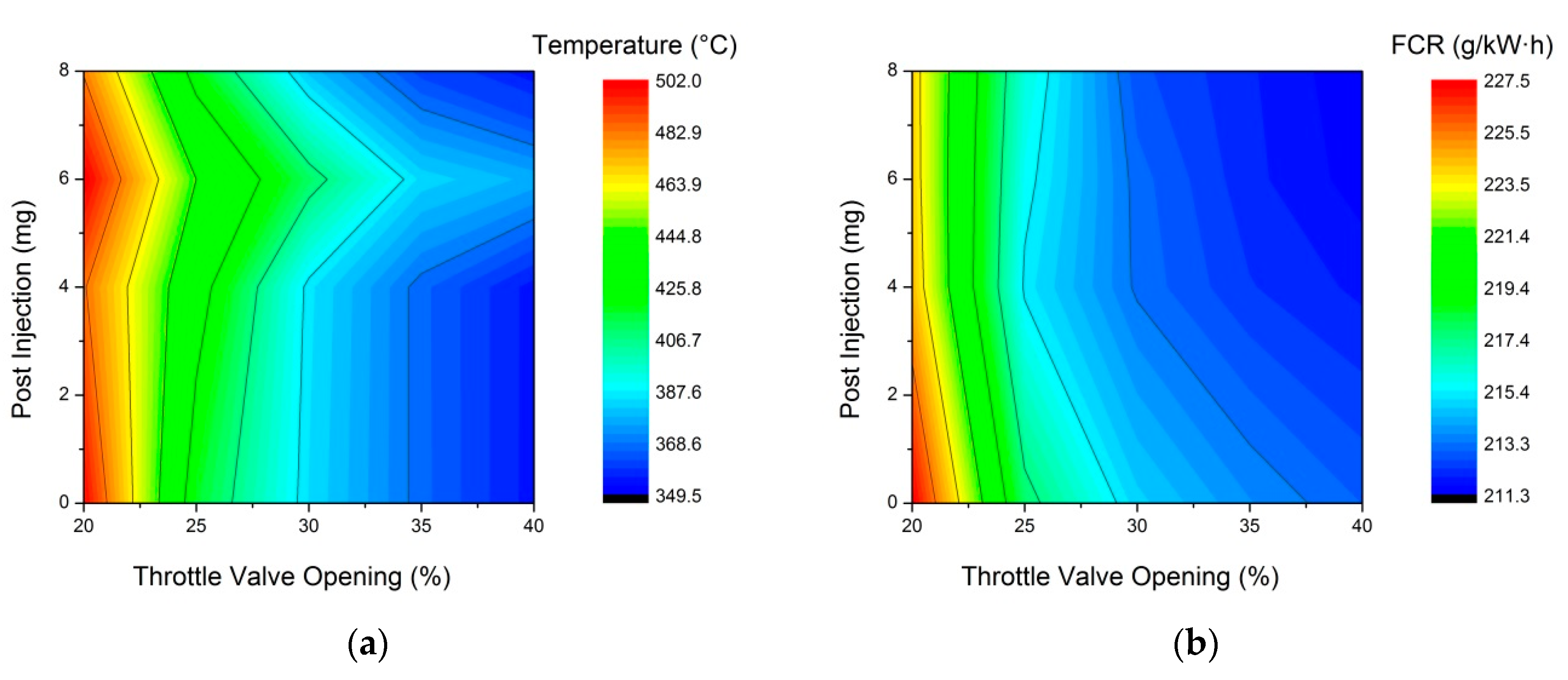
5] pointed out that decreasing the opening of the intake throttle valve, coupled with proper post injection, is an effective and efficient way to increase exhaust temperature. Passive regeneration does not require a high DPF temperature to activate. Jiao et al. [7] studied the coupling reaction between NOx and soot within DPF and suggested that continuous oxidization of soot particulates by NO2 activates at approximately 250 °C. The oxidization rate peaked at 450 °C. The soot oxidization by oxygen activates at above 450 °C, which is the main reaction process of active regeneration. The rapid oxidization by oxygen requires a drastic exhaust temperature increase, which decreases engine thermal efficiency and increases CO2 emission. Furthermore, if coupled with a WHR system, the drastic exhaust temperature increase will inevitably require the exhaust to bypass the system lest it affect the heat exchanger’s reliability. Therefore, DPF active regeneration may shut down the WHR system and hinder its energy recovery. Xie and Yang [8] suggested that rapid exhaust parameter change during working cycles may significantly reduce the thermal efficiency of the ORC system. The on-road efficiency of the ORC system was less than half of the design working point (46.72%), and the main reason for the inefficiency is operating mode switching. Frequent active regeneration should be avoided for better WHR system operation.
The application of the WHR system is likely to couple with other methods to decrease CO2 emission, such as the Miller cycle and two-stage turbocharging. The thermal efficiency increase will inevitably decrease the proportion of waste heat and reduce its quantity and especially quality. Li et al. [9] built a numerical model of a Miller cycle diesel engine focusing on engine emission. The turbocharged Miller cycle engine has produced slightly less NOx and PM emission compared to the diesel cycle. A hybrid powertrain with a diesel engine is another possible application to couple with the WHR system; the kinetic power output of the WHR system can generate electric power for storage. The working condition of the hybrid diesel engine is significantly less variable than a conventional engine [10]. However, the possible DPF active regeneration may still cause a drastic exhaust temperature increase and hinder the output of the ORC system. For EAT systems, this means a significant decrease in the exhaust temperature, which further requires optimization of the thermal management strategy. For the WHR system, this means an inevitable decrease in the waste heat quantity and a likely decrease in its quality. The quality decrease, especially exhaust temperature decrease, will also affect the WHR system downstream. Former research by Preißinger et al. [
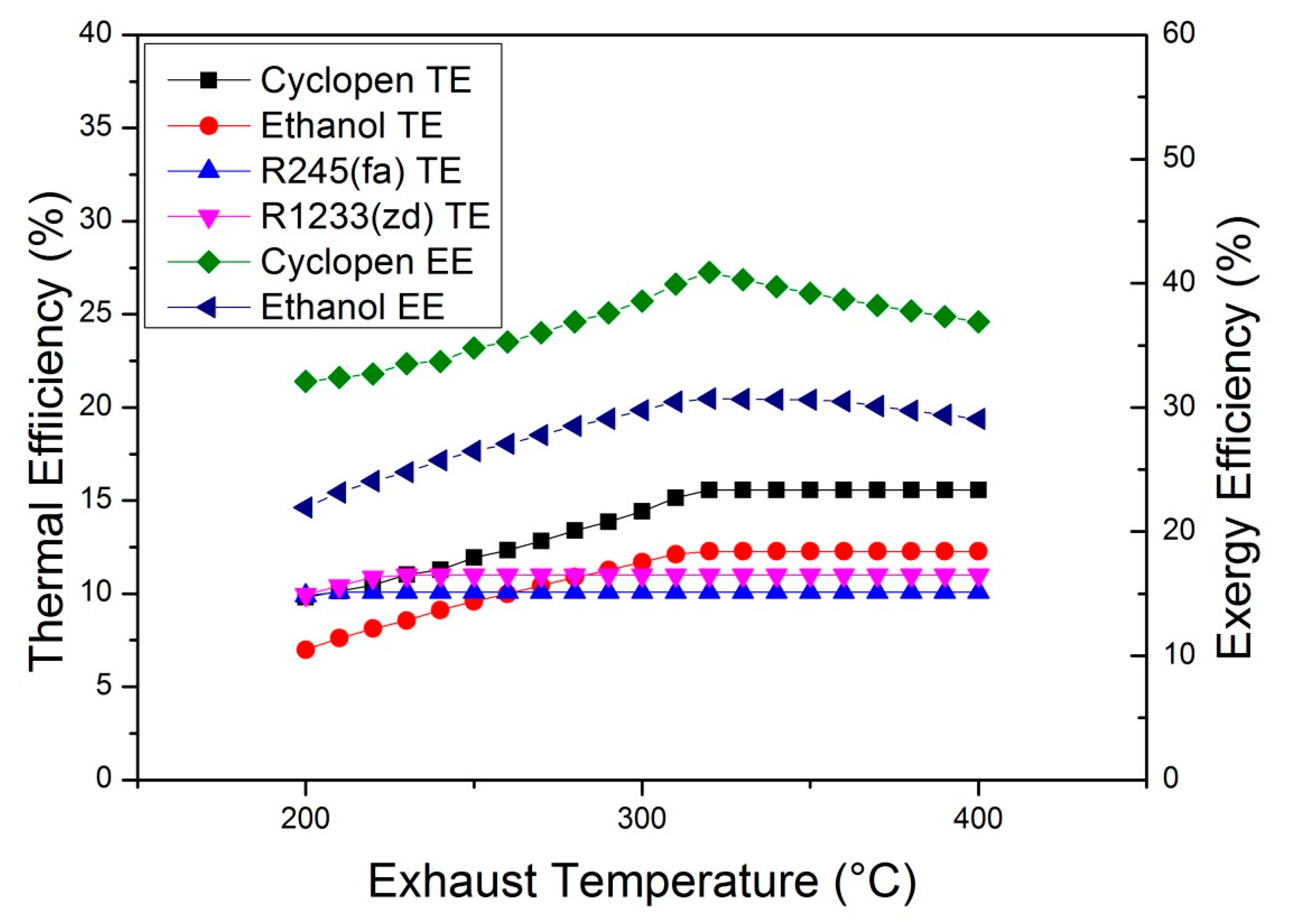
11] ranked ethanol as the best ORC working fluid for conventional heavy-duty trucks, yet at lower exhaust temperatures, the selection of working fluid needs further consideration. The confluent cascade expansion ORC system proposed by Chen et al. [12] suggested that cyclopentane is a promising working fluid for a WHR system with a lower operating temperature. Zhu et al. [13] also analyzed cyclohexane. As for even lower-quality energy recovery, Yang et al. [14] and Talluri et al. [15] suggested that R1233zd(E) has higher efficiency than the more common R245(fa). Li et al. [16] analyzed the five working fluids mentioned above for diesel engine exhaust WHR systems. At lower exhaust temperatures, the cyclopentane WHR system has the best performance in terms of exergy efficiency. It is possible to apply CO2 as the working fluid of WHR systems [17], though the extremely high cycle pressure can be difficult for practical application.
The optimization of the EAT system emission control and the WHR system efficiency have both been profoundly investigated. However, comprehensive optimization of both systems still requires further investigation. The application of the WHR system, on one hand, requires coupling with the EAT thermal management; on the other hand, it benefits from possible exhaust heat quality increase at related mid to low working points. Accordingly, the thermal management strategy of the diesel engine requires reconsideration. The active regeneration process shall be avoided to keep a relatively higher system thermal efficiency. Meanwhile, the passive regeneration reaction within the DPF shall remain at a higher rate.
Therefore, this paper proposes a comprehensive optimization of the engine, EAT system, and WHR system, both improving the EAT system clarification process and increasing the system power output. The objective is to decrease the total CO2 emission via an increase in the total system thermal efficiency, especially during mid to low exhaust temperatures, which are more common during driving cycles [
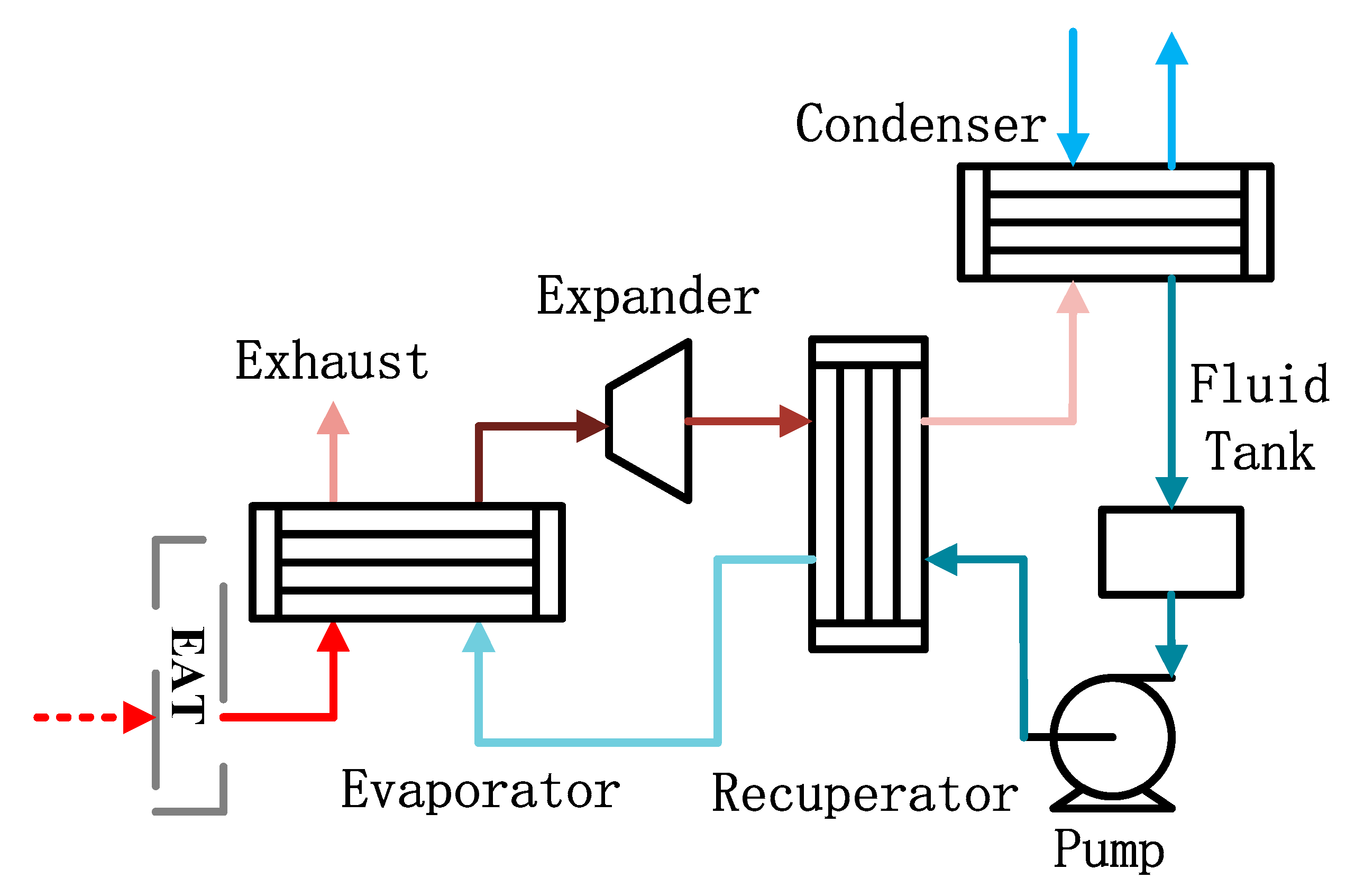
18]. First, the EAT thermal management strategy at mid to low working points is analyzed through the engine and EAT system bench test. Clarification performance and fuel consumption are both taken into consideration. Second, the WHR system model suitable for the engine is constructed based on an ORC system model. Finally, the thermal management strategy is optimized with the operation of both the EAT system and the WHR system taken into consideration.

2. Methods

2.1. Engine-EAT Experiments

Unburn HC and a proportion of PM will oxidize within DOC, which partially clarifies the exhaust and increase its temperature. Therefore, DOC is critical for EAT thermal management. Throttle valve adjusting and post injection are effective methods to increase exhaust temperature at mid to low loads [19]. Post-injection can be further divided into early post-injection (EPI) and late post injection (LPI). The combustion of the EPI fuel occurred mainly within cylinders during the later period of the combustion process, which increases the exhaust temperature before DOC. LPI is an effective method to replace the separate HC injector before DOC. The LPI fuel largely oxidizes in DOC, thus drastically increasing exhaust temperature before DPF, yet as the fuel energy barely converts into power output, the fuel consumption rate will inevitably increase.
At middle load, the engine performance in terms of thermal efficiency is relatively high, yet the high efficiency in the cylinder will inevitably decrease the heat quantity and even quality of the exhaust, causing difficulties in the clarification process of EAT devices, and decreasing the output of the WHR system. Therefore, multiple working points at middle to low loads were selected for investigation. The exhaust temperature before CDPF ranges from 221 °C to 330 °C, which was comparatively low for proper and sufficient passive regeneration. Thermal management is required to support the passive clarification of PM emission, instead of drastic temperature increase and active regeneration. Besides, the total system thermal efficiency after the management also requires further analysis. The test bench is shown in Figure 1, with measurement equipment listed in Table 1.
Five working points are selected for optimization, namely two middle working points, (1) and (2); two mid-low working points, (3) and (4); and a low working point, point (5). Data of each working point are given in Table 2.
Coupled with throttle valve adjustments, different post injection strategies were selected for comparison. For cases without LPI (E1-E3), the difference was only EPI quantity; for cases with LPI (L0-L2), the post injection quantity was fixed, the difference was LPI in proportion. Detailed cases are given in Table 3.

2.2. WHR System Modeling and Validation

This WHR system is basically an exhaust ORC system. The ORC system applied a recuperator, as high-temperature working fluid after expansion has enough heat quality for recovery. The temperature of exhaust varies in different working conditions, which can be further complicated by EAT thermal management. The WHR system structure is given in Figure 2.

2.2.1. System Modeling

The power output of a WHR system can be defined as Equation (1):
E = Q s · η = W e x p W p u m p = η e v a · m s · Δ h s · Δ h e x p Δ h e v a · η e x p m w f · Δ h p u m p η p u m p
where ms stands for heat source (exhaust) mass flow, mwf stands for working fluid mass flow, Δh stands for the enthalpy difference between the inlet and the outlet of each compartment, and η stands for the thermal efficiency of each compartment.
The WHR system power output is determined by the waste heat energy flow and thermal efficiency of the system. The thermal management at mid to low working points will increase the exhaust temperature to achieve better EAT system clarification. The WHR system downstream will inevitably be affected by this temperature increase, and heat exchangers are affected more than other system compartments. Therefore, the system model constructed in this paper applied a more detailed heat exchanger model, while other system compartments were simplified.

2.2.2. Heat Exchanger Modeling

Tube-fin heat exchanger models were used in the evaporator and recuperator of WHR system. All others were plate-fin heat exchangers for compactness and efficiency. [20] Equations of the heat exchanger model are given in Table 4. The hot side (exhaust side) of the tube-fin heat exchanger model is calculated through Equation (2), taken from Li et al. [21]. The evaporating process is calculated through Equation (5) [22], while the single phase flow of the cold side (fluid side) is calculated through the renowned Gnielinski equation [23].
After the heat transfer coefficient of the heat exchanger calculation, the heat transfer area will be calculated via log-mean temperature difference (LMTD) method:
Q = k · A · L M T D
where k stands for the total heat transfer coefficient, A stands for the equivalent collecting area of the heat exchanger. The efficiency of the evaporator is the proportion of waste heat absorbed by working fluid, or working fluid enthalpy increase divided by heat source enthalpy decrease:
η e v a = Q e v a Q s = Δ h e v a Δ h s
As the exhaust heat quality increase, the evaporation pressure at evaporator should increase accordingly to properly increase WHR system thermal efficiency, namely, increase Δhexp of Equation (1). In this heat exchanger model, the optimal evaporation pressure is evaluated by restrictions of the evaporator. Namely, the evaporation pressure cannot surpass 3 MPa, and the pinch point temperature difference (PPTD) of the evaporator cannot surpass 20 K. Both restrictions are due to practical manufacturing difficulties.
The WHR system also applied a recuperator for better thermal efficiency. The recuperator model is largely identical to the evaporator model, with recuperate rate fixed at 50%. The condenser model was simplified. Working fluid condensing did not consume extra power. Working fluid condensed at the set temperature.

2.2.3. Expander and Pump Modeling

The models of other system components, namely expanders and pumps, are simplified. The power output of an expander is determined by the expansion ratio and the isentropic efficiency:
W e x p = Q e v a · Δ h e x p Δ h e v a · η e x p
η e x p = Δ h e x p Δ h i s o
where Δhiso is the working fluid enthalpy decrease of an isentropic expansion. To achieve proper expansion at higher evaporation temperature, expanders of the WHR systems are piston expanders. The expansion ratio is determined by evaporator and condenser parameters, while the isentropic efficiency is taken from Bao et al. [24].
Models of pumps are similar to expanders:
W p u m p = m r · Δ h p u m p η p u m p
η p u m p = Δ h i s o Δ h p u m p
The related WHR system parameters are given in Table 5.

2.2.4. Assumptions

The actual operating conditions of on-road diesel engines are complicated. The high exhaust temperature at higher working points required no thermal management. As suggested by Xie and Yang [8], the efficiency of the WHR system at a higher working point may vary significantly from the on-road efficiency. The following assumptions are made for the WHR system model to better optimize the thermal management strategy.
  • The WHR system has constant exhaust inlet temperature and flow rate at all working points.
  • The evaporation pressures may alter at different exhaust temperatures to achieve the highest WHR system output, which is capped at 3 MPa.
  • The parameters of the WHR systems in Table 5 remain constant.
  • Pressure drop and heat transfer loss of condenser and pipelines are ignored.

2.2.5. Model Validation

The attached heat exchanger model was validated with a heat exchanger bench test, as shown in Figure 3. Electric heated or water cooled exhaust served as a substitute for actual engine exhaust at each working point.
Table 6 lists the measurement devices and the accordingly measurement range and the accuracy of the sensors. The dependent variable uncertainty is calculated based on Equation (12):
η R = [ R x 1 · w 1 2 + R x 2 · w 2 2 + + R x n · w n 2 ] 1 / 2
where R represents the function of independent variables and w is referred to their uncertainties. The verification of the detailed heat exchanger model is given in Figure 4. The exhaust during verification has fixed inlet temperatures. The heat exchanger model was evaluated through the heat exchanging quantity, which is determined by exhaust outlet temperature at different flow rates. The error of the simulation model is well below 5%.

3. Results and Analysis

3.1. Effect of Thermal Management on EAT System Clarification Process

The reaction between PM and NOx is given in Figure 5, as suggested by Jiao et al. [7]. For CDPF passive regeneration, the reaction between soot and NOx activates at exhaust temperatures above 250 °C, though the heat transfer is hindered by the limited temperature difference, which in turn limited the reaction rate between NOx and PM. Exhaust temperature above 300 °C is possible to heat the catalyst to a higher reaction rate, and an even higher temperature can achieve a more rapid catalyst temperature increase. The reaction rate from 400 s to 450 s has increased significantly, especially with exhaust temperature at 400 °C. At higher exhaust temperatures, a significant proportion of soot is oxidized by oxygen, which increased the possibility of active regeneration and rapid exhaust temperature increase. At 900 s, the difference in the reaction rate of NOx at different exhaust temperatures is less significant. Therefore, the exhaust temperature before DPF is better kept at between 300–400 °C, to keep a higher CDPF passive reaction rate.
A conventional EAT system of a diesel engine requires NOx clarification devices, especially Selective Catalytic Reduction (SCR), besides fore mentioned PM clarification devices. Exhaust thermal management at mid to low working points is also beneficial to SCR. On one hand, exhaust temperature at mid to low working points (200–300 °C) is relatively low for the SCR, the reaction benefits from exhaust temperature increase; on the other hand, the NO oxidization within DOC also benefits from this increase, a larger proportion of NO2 will further increase the total reaction rate within SCR. The possible benefit of the SCR reaction rate is shown in Figure 6. After thermal management, the NOx emission decreased by an average of 36%.

3.2. Effect of Thermal Management on EAT System Waste Heat Flow

To achieve better passive regeneration within the CDPF without starting an active regeneration, the exhaust temperature upstream shall be raised to above 250 °C, without reaching 450 °C. With power output remaining constant, a decrease in engine intake quantity will decrease exhaust quantity accordingly, and the waste heat quality within the exhaust will proportionally increase. Meanwhile, if the combustion process is delayed, a higher proportion of the combustion energy will remain in the exhaust rather than generate power output. Therefore, engine intake air flow and post injection affect combustion efficiency and exhaust temperature, the test result at working point (1) is shown in Figure 7.
Adjusting intake quantity through adjusting the throttle valve has a more significant effect on exhaust temperature. Moderate valve opening decrease did not significantly affect the combustion process, as shown by only a limited fuel consumption rate increase. The exhaust temperature increase was mainly the result of the air flow quantity decrease. At 35% and 40% valve opening, the exhaust temperature increased by an average of 18.43 °C and 30.25 °C respectively, with the fuel consumption rate increased by no more than 1%. As for cases with significant throttle valve opening decrease, the reduction of intake quantity deteriorated the combustion process, which sharply increased the exhaust temperature at the cost of system thermal efficiency. At 20% valve opening, the average exhaust temperature increase was 164.06 °C, with the average fuel consumption rate increased by 7.72%.
The exhaust temperature and the fuel consumption rate at different post injection strategies are shown in Figure 8. Experiment results at working point (1) were selected as a comparison to analyze the effect of EPI and LPI on engine emission and thermal efficiency. The total post injection quantity remained constant at 8 g/cycle, as well as other boundary conditions. Coupled with throttle valve opening adjustments, post injection further increased the temperature of the exhaust, and the difference between the two cases is significant. The combustion of the EPI fuel occurred mainly within the cylinder during the later period of the combustion process, the combustion energy of the post injection fuel was partly converted to the power output; while the LPI fuel was largely oxidized in the DOC, which increased exhaust temperature at the cost of fuel consumption rate. With EPI only, the average temperature increase was merely 1.4 °C at 30% to 40% valve opening; the maximum increase at 20% valve opening was 4.4 °C. However, the fuel consumption rate after the application of EPI was slightly improved. The main reason for this increase is the excess air factor of the main combustion was relatively improved and partly compensated for the loss. The application of LPI significantly increased the exhaust temperature, at the cost of thermal efficiency. At the same power output, valve opening and post injection quantity, 50% LPI increased the exhaust temperature by 41.2–72.8 °C, with the fuel consumption rate increased by 8.1–8.8%.

3.3. Effect of the EAT Thermal Management on the WHR System

Exhaust heat quality improved by thermal management strategies at fore mentioned working points is also beneficial for WHR systems’ thermal and exergy efficiency. Effects on the WHR systems require further analysis to comprehensively optimize the EAT thermal management strategy, in terms of total thermal efficiency.
At the selected temperature range, the thermal and exergy efficiencies of the exhaust WHR system, as shown in Figure 9, are both largely affected by the exhaust temperature. The effect on thermal efficiency is more significant at a lower temperature, especially for working fluids with higher evaporating temperatures, since the limited evaporation temperature decreased evaporation pressure. Both cyclopentane and ethanol systems’ evaporation pressure falls to below 1 MPa at 200 °C, with thermal efficiency decreased by 37.11% and 43.02% compared to systems with high exhaust temperature. The thermal efficiency reached its maximum at 320 °C as the evaporating temperature was finally capable to reach the maximum evaporation pressure of 3 MPa. This is further explained by the exergy efficiency, which is further affected by the WHR system heat flux. Exhaust with higher temperature has proportionally more exergy for recovery, while higher waste heat efficiency requires a WHR system with higher evaporate pressure. A WHR system with evaporate pressure above 3 MPa requires heat exchangers with increased reliability; evaporate temperature above 250 °C also requires special lubrication. Both factors may increase the system cost. Therefore, an exhaust temperature of around 320 °C is optimal for the WHR system of this paper.
The fore mentioned EAT thermal management is mainly focused on better CDPF passive regeneration. Therefore, the exhaust temperature before CDPF shall be between 300~400 °C. Also shown in Figure 9, the thermal efficiency of the cyclopentane WHR system within this temperature range is significantly higher than the second (ethanol) by 26.69% on average. R245fa and R1233zd systems retained considerable thermal efficiency at low temperatures. However, at below 250 °C, the passive regeneration will not activate in CDPF, thus out of the WHR system operation range considered in this paper.

4. Discussion

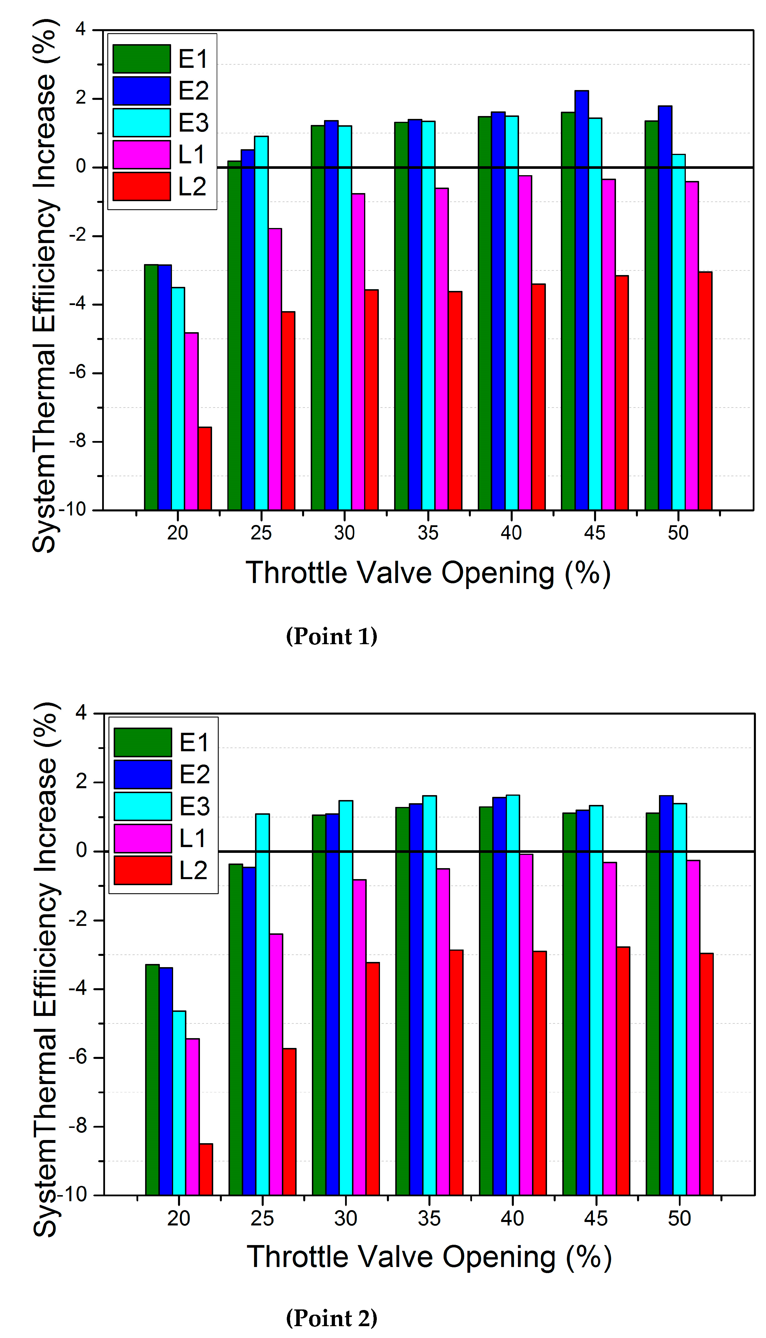
Coupled with different exhaust thermal management strategies, the WHR system power output increase of working point (1) is shown in Figure 10. As the effect of throttle valve opening on the exhaust temperature is significant, the WHR system efficiency increase is accordingly significant in cases with small valve opening, while efficiency increase in cases with moderate valve opening is also moderate. The effect of LPI is similar, where the WHR system efficiency showed significant increases in cases with LPI, and the maximum efficiency increase occurred in cases with 20% valve opening and 2 mg LPI (case L1). However, the drastic efficiency increase was at the cost of fuel consumption. The thermal efficiency of the organic Rankine cycle of the WHR system is much lower than the Diesel cycle of the engine. Therefore, the efficiency increase of the WHR system can only partly compensate for the efficiency decrease of the engine. Further proof can be seen in Figure 11.
Coupled with the exhaust WHR system, the thermal efficiency variation of the system at middle load is given in Figure 11. In cases with small valve openings or with LPI, the WHR system coupled with thermal management cannot improve the total thermal efficiency of the system. The efficiency decrease caused by worse combustion cannot be compensated by the WHR system efficiency increase. Besides, the high exhaust temperature of these cases may start active regeneration within the CDPF, rapid exhaust temperature increase requires a temporary shutdown to protect the WHR system, achieved by opening the bypass valve before the evaporator. Frequent thermal impacts will repeatedly interrupt the operation of the WHR system, decreasing its power output and affecting its reliability. Cases with moderate throttle valve opening adjustments and EPI have better thermal efficiency. The highest total thermal efficiency increase is achieved with an opening above 40% and with EPI only. The highest relative increases are 2.23% and 1.64% at working point 1 and 2; the WHR system increased system output by 5.74% and 5.27% respectively.
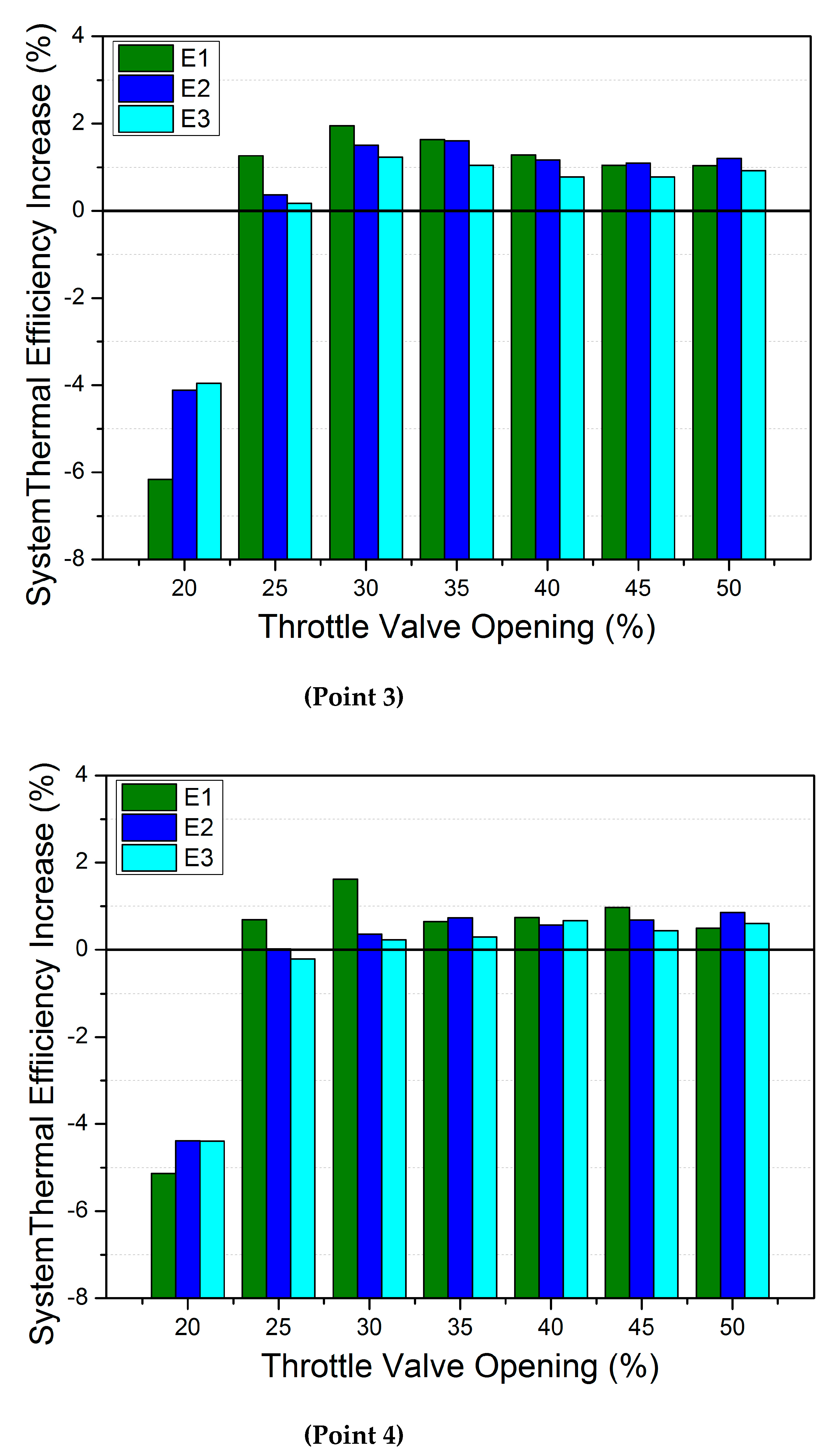
The situation of mid-low load working points is largely identical, as shown in Figure 12. The major difference is the highest total thermal efficiency increase of the two working points is achieved with an opening of 30%. This is mainly because the exhaust temperature at mid-low working points is lower than at middle load. Therefore, a more drastic temperature increase is required for a significant WHR system efficiency increase. The highest relative increases are 1.95% and 1.62% at working point 3 and 4; the WHR system increased system output by 5.98% and 5.78% respectively. As already shown in Figure 9, the exergy efficiency of the WHR system has come to a maximum with an exhaust temperature of around 320 °C. The exhaust temperatures of the four optimal cases are between 315~337 °C, which supported the suggestion. Meanwhile, the temperatures before CDPF are between 342~364 °C, also optimal for passive regeneration.
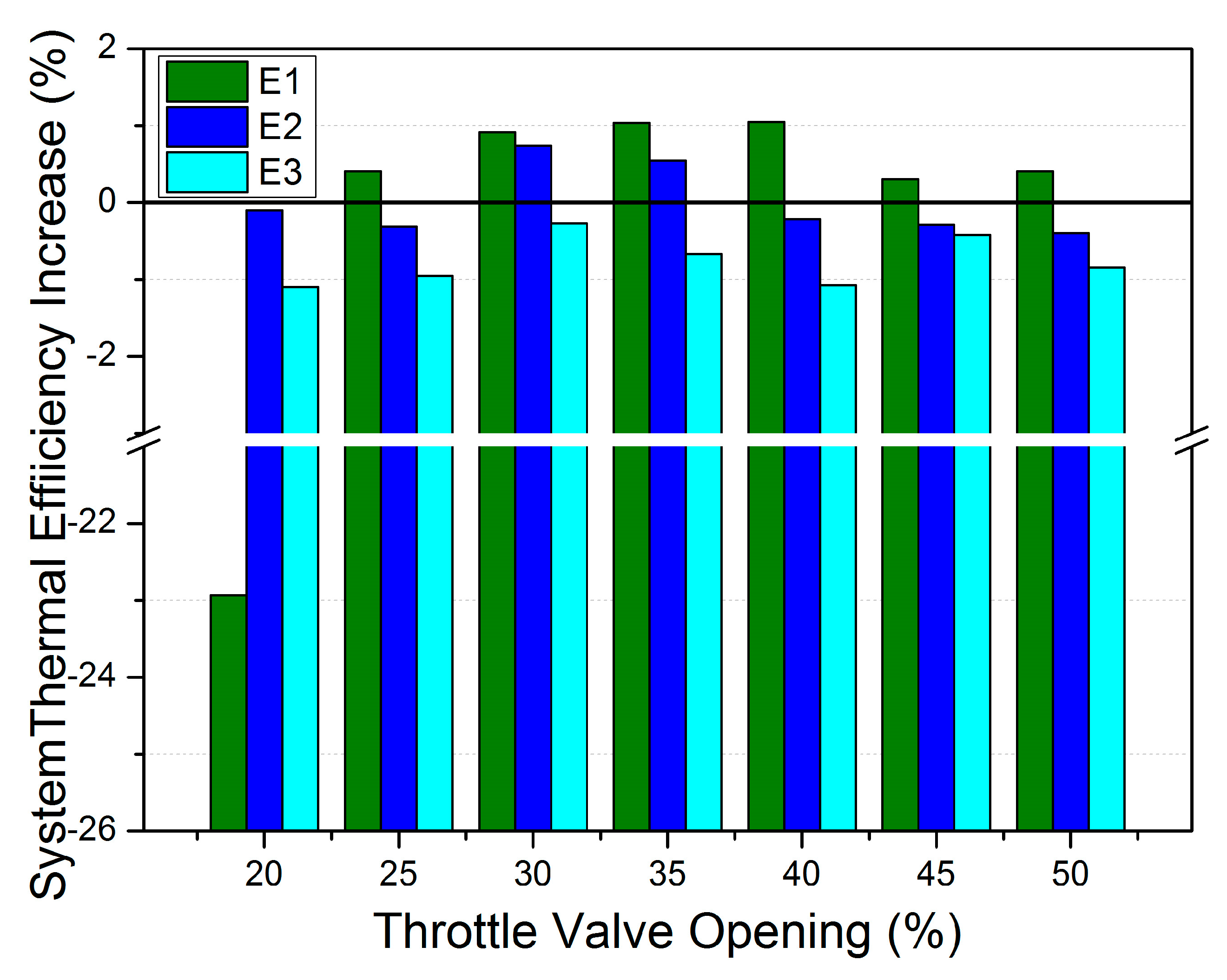
The system thermal efficiency at low load, as shown in Figure 13, has further issues in system output. At low load, the efficiency increase through thermal management is less significant, as the exhaust temperature of working point 5 is only 222.26 °C, even after thermal management, the exhaust temperature is still rather low; all cases are below 300 °C, except when throttle opening at 20%. The total thermal efficiency increase of the exhaust WHR system is only 1.05% at the highest case, with WHR system output at 0.67 kW, insignificant for recovery.
The average exergy loss of system units are given in Table 7. Major energy loss appeared in evaporators and expanders. The optimization of thermal management has improved the performance of largely the whole system. The only exception was pump, which has only limited proportion in total loss.
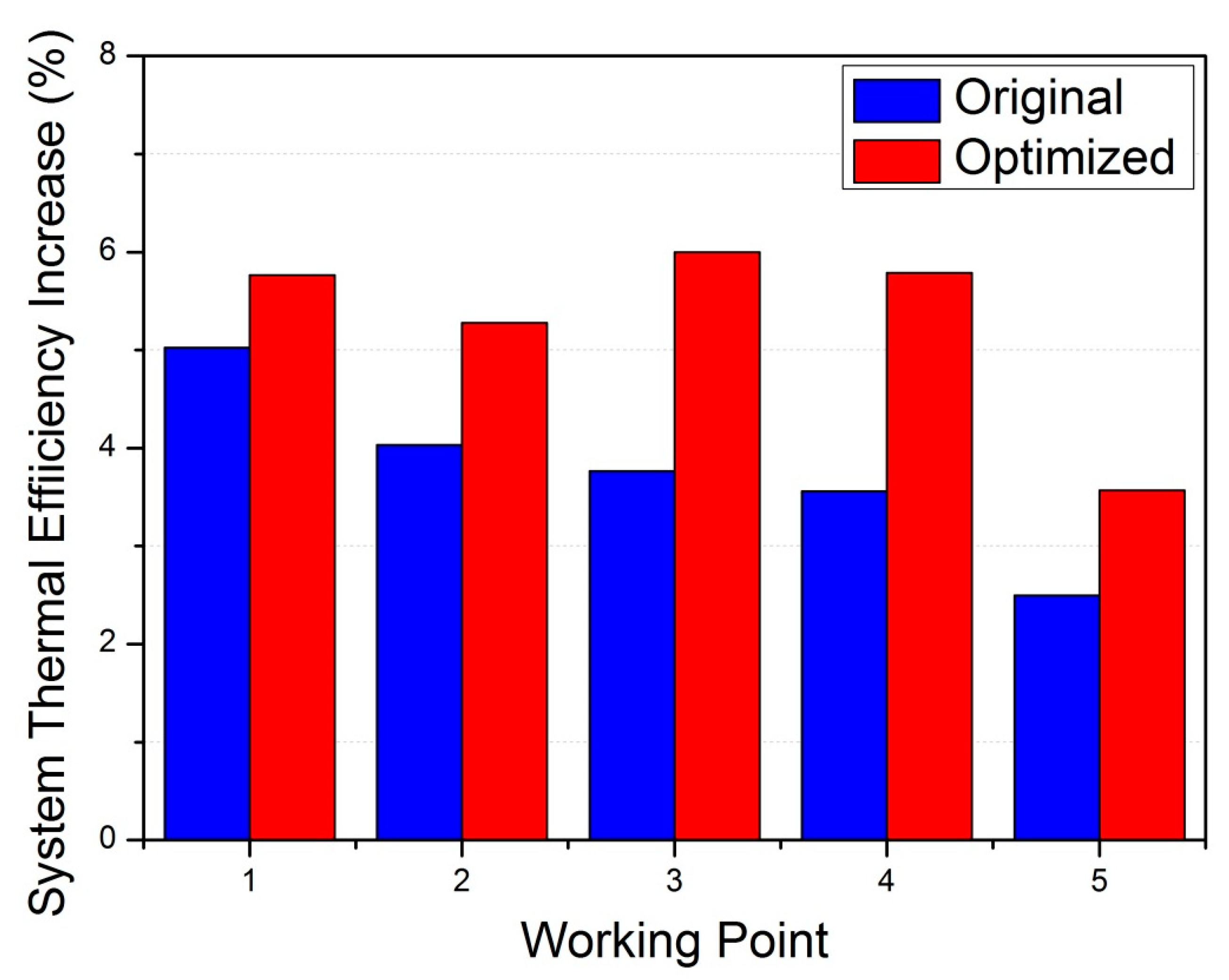
The optimal EAT thermal management strategy increased exhaust temperature to between 300~330 °C, the increase in exhaust energy quality has considerable effect on WHR system downstream, especially for mid-low working points. The increase, as shown in Figure 14, is 14.73% and 30.87% at mid working points (1) and (2); at mid-low working points, the increase is 59.2% and 62.55% at points (3) and (4), which is roughly the twice of point (2). Also shown in Figure 14, the relative output of exhaust WHR system has decreased gradually as exhaust temperature decreased, while the optimal strategy increased system thermal efficiency by an average of 5.71%. At low working point of point (5), the increase is 43.01%, though the relative power output increase is 3.57%, smaller than at mid or mid-low working points, and the actual power output increase is merely 1.12 kW. Activating the WHR system at low working point is less necessary.

5. Conclusions

In this paper, the thermal management of EAT system is optimized to achieve better thermal efficiency in both the diesel engine and WHR system. The exhaust temperature at mid and mid-low working points was increased to improve EAT devices’ performance, and the WHR system was optimized accordingly.
(1)
At mid to low working points, increasing exhaust temperature to 300~350 °C benefits both EAT system and the WHR system. Clarification reactions of PM and NOx both benefited from this temperature increase. Meanwhile, the WHR system model reached optimal exergy efficiency with an exhaust temperature of 320 °C.
(2)
Moderate throttle valve adjustment coupled with EPI could effectively achieve the required temperature increase, with the fuel consumption rate increased by no more than 1%. The significant increase of low valve opening or LPI, though increased the WHR system output by more than 80%, the considerable decrease in engine thermal efficiency decreased the total system efficiency in all cases.
(3)
The optimal strategy increased WHR output by 14.73%, 30.87%, 59.2%, and 62.55% at selected mid and mid-low working points. Thermal management has increased system thermal efficiency by an average of 5.71%. Activating the WHR system at a low working point is less necessary, due to the limited output.

Author Contributions

Conceptualization, D.L.; methodology, D.L.; software, D.L.; validation, D.L.; formal analysis, D.L.; investigation, D.L.; resources, K.S., S.B. and G.L.; data curation, D.L. and K.S.; writing—original draft preparation, D.L.; writing—review and editing, S.Z., G.Z. and H.C.; visualization, G.Z. and D.L.; supervision, S.Z.; project administration, K.S.; funding acquisition, S.B. and G.L. All authors have read and agreed to the published version of the manuscript.

Funding

This work was funded by National Engineering Laboratory for Mobile Source Emission Control Technology of China [grant number NELMS2019A01], and the Undergraduate School of Shandong University, China [grant number 2022Y155].

Data Availability Statement

All data and models used in the study appear in the submitted article.

Acknowledgments

I personally appreciate the editors and reviewers for their constructive and detailed critiques contributed to the quality of this paper.

Conflicts of Interest

The authors declare no conflict of interest.

Nomenclature

SymbolUnitsDescription
Am2heat exchanging area
dmmdiameter
EkWpower output
hkJ/kgenthalpy
kW/m2·Kheat transfer coefficient
mkg/smass flow rate
Nu-Nusselt number
Pr-Prandtl number
QkWheat flux
Re-Reynolds number
smmdistance
α-Low-Reynolds-Number coefficient
η%efficiency
Subscripts
SymbolDescription
evaevaporator
expexpander
ininlet
outoutlet
sheat source
rerecuperated
wfworking fluid
Acronyms
SymbolDescription
CO2Carbon dioxide
DOCDiesel Oxidation Catalyst
DPFDiesel Particulate Filter
EATExhaust Aftertreatment
EPIEarly Post Injection
LMTDLog-Mean Temperature Difference
LPILate Post Injection
NONitrogen Monoxide
NO2Nitrogen Dioxide
NOxNitrogen Oxide
ORCOrganic Rankine Cycle
PMParticulate Matter
PPTDpinch point temperature difference
SCRSelective Catalytic Reduction
WHRWaste Heat Recovery

References

  1. Lin, B.; Benjamin, N. Influencing factors on carbon emissions in China transport industry. A new evidence from quantile regression analysis. J. Clean. Prod. 2017, 150, 175–187. [Google Scholar] [CrossRef]
  2. Lion, S.; Michos, C.; Vlaskos, I.; Rouaud, C.; Taccani, R. A review of waste heat recovery and organic Rankine cycles (ORC) in on-off highway vehicle heavy duty diesel engine applications. Renew. Sustain. Energy Rev. 2017, 79, 691–708. [Google Scholar] [CrossRef]
  3. Huang, Y.; Ng, E.; Surawski, N.; Zhou, J.; Wang, X.; Gao, J.; Lin, W.; Brown, R. Effect of diesel particulate filter regeneration on fuel consumption and emissions performance under real-driving conditions. Fuel 2022, 320, 123937. [Google Scholar] [CrossRef]
  4. Rothe, D.; Knauer, M.; Emmerling, G.; Deyerling, D.; Niessner, R. Emissions during active regeneration of a diesel particulate filter on a heavy duty diesel engine: Stationary tests. J. Aerosol Sci. 2015, 90, 14–25. [Google Scholar] [CrossRef]
  5. Bai, S.; Tang, J.; Wang, G.; Li, G. Soot loading estimation model and passive regeneration characteristics of DPF system for heavy-duty engine. Appl. Therm. Eng. 2016, 100, 1292–1298. [Google Scholar] [CrossRef]
  6. Feng, X.; Ge, Y.; Ma, C.; Tan, J.; Yu, L.; Li, J.; Wang, X. Experimental study on the nitrogen dioxide and particulate matter emissions from diesel engine retrofitted with particulate oxidation catalyst. Sci. Total Environ. 2014, 15, 56–62. [Google Scholar] [CrossRef]
  7. Jiao, P.; Li, Z.; Shen, B.; Zhang, W.; Kong, X.; Jiang, R. Research of DPF regeneration with NOx-PM coupled chemical reaction. Appl. Therm. Eng. 2017, 110, 737–745. [Google Scholar] [CrossRef]
  8. Xie, H.; Yang, C. Dynamic behavior of Rankine cycle system for waste heat recovery of heavy duty diesel engines under driving cycle. Appl. Energy 2013, 112, 130–141. [Google Scholar] [CrossRef]
  9. Wang, D.; Shi, L.; Zhang, H.; Li, X.; Qian, Y.; Deng, K. Research on influence and demand of Miller cycle based on the coupling of marine low-speed engine and turbocharger. Appl. Therm. Eng. 2022, 200, 117624. [Google Scholar] [CrossRef]
  10. Li, C.; Wang, Y.; Jia, B.; Roskilly, A. Application of Miller cycle with turbocharger and ethanol to reduce NOx and particulates emissions from diesel engine—A numerical approach with model validations. Appl. Therm. Eng. 2019, 150, 904–911. [Google Scholar] [CrossRef]
  11. Preißinger, M.; Schwöbel, J.A.; Klamt, A.; Brüggemann, D. Multi-criteria evaluation of several million working fluids for waste heat recovery by means of rganic Rankine Cycle in passenger cars and heavy-duty trucks. Appl. Energy 2017, 206, 887–899. [Google Scholar] [CrossRef]
  12. Chen, T.; Zhuge, W.; Zhang, Y.; Zhang, L. A novel cascade organic Rankine cycle (ORC) system for waste heat recovery of truck diesel engines. Energy Convers. Manag. 2017, 138, 210–223. [Google Scholar] [CrossRef]
  13. Zhu, Y.; Li, W.; Sun, G.; Li, H. Thermo-economic analysis based on objective functions of an organic Rankine cycle for waste heat recovery from marine diesel engine. Energy 2018, 158, 343–356. [Google Scholar] [CrossRef]
  14. Yang, J.; Ye, Z.; Yu, B.; Ouyang, H.; Chen, J. Simultaneous experimental comparison of low-GWP refrigerants as drop-in replacements to R245fa for Organic Rankine cycle application. R1234ze(Z), R1233zd(E), and R1336mzz(E). Energy 2019, 173, 721–731. [Google Scholar] [CrossRef]
  15. Talluri, L.; Dumont, O.; Manfrida, G.; Lemort, V.; Fiaschi, D. Experimental investigation of an Organic Rankine Cycle Tesla turbine working with R1233zd(E). Appl. Therm. Eng. 2020, 174, 115293. [Google Scholar] [CrossRef]
  16. Li, D.; Sun, Q.; Sun, K.; Zhang, G.; Bai, S.; Li, G. Diesel engine waste heat recovery system comprehensive optimization based on system and heat exchanger simulation. Open Phys. 2021, 19, 331–340. [Google Scholar] [CrossRef]
  17. Li, X.; Tian, H.; Shu, G.; Zhao, M.; Markides, C.; Hu, C. Potential of carbon dioxide transcritical power cycle waste-heat recovery systems for heavy-duty truck engines. Appl. Energy 2019, 250, 1581–1599. [Google Scholar] [CrossRef]
  18. Yang, C.; Wang, W.; Xie, H. An efficiency model and optimal control of the vehicular diesel exhaust heat recovery system using an organic Rankine cycle. Energy 2019, 171, 547–555. [Google Scholar] [CrossRef]
  19. Bai, S.; Chen, G.; Sun, Q.; Wang, G.; Li, G. Influence of active control strategies on exhaust thermal management for diesel particular filter active regeneration. Appl. Therm. Eng. 2017, 119, 297–303. [Google Scholar] [CrossRef]
  20. Holik, M.; Živić, M.; Virag, Z.; Barac, A. Optimization of an organic Rankine cycle constrained by the application of compact heat exchangers. Energy Convers. Manag. 2019, 188, 333–345. [Google Scholar] [CrossRef]
  21. Li, W.; Tao, W.; Kang, H.; Li, H.; Xin, R. Experimental study on heat transfer and pressure drop characteristics for fin-and-tube heat exchangers. Chin. J. Mech. Eng. 1997, 33, 81–86. [Google Scholar] [CrossRef]
  22. Kew, P.; Cornwell, K. Correlations for the prediction of boiling heat transfer in small-diameter channels. Appl. Therm. Eng. 1997, 17, 705–715. [Google Scholar] [CrossRef]
  23. Kandylas, I.; Stamatelos, A. Engine exhaust system design based on heat transfer computation. Energy Convers. Manag. 1999, 40, 1057–1072. [Google Scholar] [CrossRef]
  24. Bao, J.; Zhao, L. A review of working fluid and expander selections for organic Rankine cycle. Renew. Sustain. Energy Rev. 2013, 24, 325–342. [Google Scholar] [CrossRef]
Figure 1. Diesel Engine and EAT Test Bench (a) and Structure (b).
Processes 11 01252 g001
Figure 2. WHR System Structure.
Processes 11 01252 g002
Figure 3. Heat Exchanger Test Bench (a) and Structure (b).
Processes 11 01252 g003
Figure 4. Validation of WHR heat exchanger Model.
Processes 11 01252 g004
Figure 5. PM passive regeneration rate at different exhaust temperatures.
Processes 11 01252 g005
Figure 6. NOx emission at different exhaust conditions.
Processes 11 01252 g006
Figure 7. Effect of EPI on exhaust temperature (a) and fuel consumption rate (b).
Processes 11 01252 g007
Figure 8. Effect of post injection on exhaust temperature and thermal efficiency.
Processes 11 01252 g008
Figure 9. Thermal and exergy efficiency of exhaust WHR system.
Processes 11 01252 g009
Figure 10. WHR System Output Increase (Point 1).
Processes 11 01252 g010
Figure 11. System Thermal Efficiency Variation (Mid Load).
Processes 11 01252 g011
Figure 12. System Thermal Efficiency Variation (Mid-Low Load).
Processes 11 01252 g012
Figure 13. System Thermal Efficiency Variation (Low Load).
Processes 11 01252 g013
Figure 14. Total System Efficiency Variation of exhaust WHR system.
Processes 11 01252 g014
Table 1. Related measurement equipment.
MeasurementModelMeasuring PrincipleAccuracy of Measurement
PowerINDYS66JD0–250 kWSpeed: ±1 r/min
Torque: ±0.1%FS
Fuel consumptionFC2212L0.1–70 kg/h±0.2%
TemperatureRTD100−100 °C–500 °C±0.5%
Exhaust gas analyzerI60NOx: CLD1 ppm
Opacimeter483Photoacoustic±5 μg
PressureElectronic0–2000 kPa±0.5%
Mass flowCoriolis0–0.4 kg/s±0.5%
Table 2. Exhaust Waste Heat at Selected Working Points.
Working Point12345
Temperature (°C)324.42309.88296.60278.43229.00
Mass Flow (kg/h)1152.41081.7965.6712.7544.1
Table 3. Post injection strategies during the bench test.
CaseE1E2E3/L0L1L2
EPI Quantity (mg)46864
LPI Quantity (mg)00024
Table 4. Equations of Heat Exchanger Model.
Heat ExchangerEquations
Tube-fin Hot Side N u = 0.982 · R e 0.424 · ( s d 3 ) 0.0887 · ( N · s 2 d 3 ) 0.159 (2)
Other Single Phase N u = f 8 · R e 1000 · P r / [ 12.7 · f 8 0.5 · P r 2 / 3 1 + 1.07 ] (3)
f = 1.82 · l g R e 1.5 2 (4)
Evaporation/Two Phase h t p = 30 · R e l o 0.857 · B o 0.714 · ( 1 x ) 0.143 · k l d (5)
Table 5. WHR System Parameter.
SectionParameter
Heat Exchanger Efficiency %95
Superheat Degree K10
Undercooling Degree K10
Evaporator PTD K20
Condenser PTD K10
Expander Efficiency %60
Pump Efficiency %40
Environment Temperature °C25
Table 6. Measurement Devices Accuracy.
MeasurementTypeRangeAccuracy
TemperatureRTD100−100 °C–+400 °C±0.5%
PressureElectronic pressure transducer (gauge)0–2000 kPa±0.5%
Mass flow rateCoriolis effect0–0.4 kg/s±0.5%
Table 7. Exergy Loss of Original and Optimized WHR System Units.
System UnitEvaporatorExpanderCondenserPumpRecuperator
Original Loss %24.2431.825.532.584.21
Optimized Loss %15.8422.073.922.533.36
Disclaimer/Publisher’s Note: The statements, opinions and data contained in all publications are solely those of the individual author(s) and contributor(s) and not of MDPI and/or the editor(s). MDPI and/or the editor(s) disclaim responsibility for any injury to people or property resulting from any ideas, methods, instructions or products referred to in the content.

