Article

Effect of Processing Technology on Mechanical Properties of HRB500 High-Strength Steel Bar Threading

1
School of Mechanical Engineering, Hebei University of Science and Technology, Shijiazhuang 050018, China
2
College of Environmental Sciences and Engineering, Hebei University of Science and Technology, Shijiazhuang 050018, China
*
Author to whom correspondence should be addressed.
Processes 2023, 11(4), 1223; https://doi.org/10.3390/pr11041223
Submission received: 28 February 2023 / Revised: 10 April 2023 / Accepted: 11 April 2023 / Published: 15 April 2023

Abstract

:
The processing quality of steel bar thread has a large influence on its performance. Using the traditional thread processing technology, it is difficult to meet the requirements of steel bar thread processing with large diameter and high strength. A technical process for HRB500 high-strength steel bar thread processing, including face milling, rib stripping, chamfering, necking formation, and thread rolling, was proposed. The influences of cutting parameters on the cutting force of steel bar surface in face milling were analyzed by the finite element method. For the necking formation process, the effect of springback amount on necking formation was studied. The main parameters in rolling formation were analyzed and calculated, including extrusion pressure, rolling speed, and rolling feed. Experiments for uniaxial tensile of the processed high-strength steel bar threads were carried out. The results showed that cutting depth has the largest influence on the cutting force; the second is feed rate. The effect of the spindle speed was lowest during the face milling. After the necking formation process, the values of the maximum springback amount along the X, Y, and Z directions were 0.05 mm, 0.06 mm, and 0.98 mm, respectively. The finished thread met the precision and quality requirements of a grade I joint. This study provides a high-quality processing technology for large-diameter and high-strength steel bar threads.

1. Introduction

Nowadays, reinforced concrete structures are widely used in engineering construction [1]. Compared with ordinary steel bar, high-strength steel bar has excellent mechanical properties. For the same strength requirements, the use of high-strength steel bar significantly reduces the number of steel bars used and improves utilization of space [2,3,4]. Therefore, it is necessary to promote the use of high-strength steel bars in practical projects [5]. The strength and mechanical properties of HRB500 high-strength steel bar is improved by the micro-alloying technology [6,7]. High-strength steel bars increase the strength and dimensions of the parent material (Figure 1a), so traditional thread processing tools are not able to meet the processing requirements. In addition, transverse and longitudinal ribs on the surface of the bars affect the accuracy of thread formation (Figure 1b). As a result, the machined threads of high-strength steel bars have a lack of tooth shape, low thread accuracy, and low thread roundness [8].
Concerning these issues, many researchers have conducted in-depth research on the thread forming process, such as face milling and thread rolling. In recent decades, face milling has been observed as a vital process in the thread steel manufacturing field. Various researchers have studied the influence of numerous process parameters in the milling process, such as cutting speed [9], feed rate [10], depth of cut [11], tool angle [12], impact angle [13], and microstructure and hardness of the tool [14]. The finite element model (FEM) is widely used to determine various physical interactions that occur during machining. Wojciechowski et al. [15] proposed a numerical model for the minimization of vibrations and cutting force during precise ball-end milling while considering the tool overhang and surface inclination angle. It was concluded that cutting force decreases with an increase of surface inclination. Pelayo [16] reported the static and dynamic behavior of a time-domain model as a checking tool. It was found that, with an increase in depth of cut and feed rate, the cutting forces increases. Wan et al. [17] reviewed the progress of milling research using the finite element method. To simulate complex machining processes, many numerical models have evolved from 2D models to 3D models. In summary, research on milling parameters by the finite element method has received extensive attention, but the relevant research results are devoted to the study of tool durability, with a lack of research on machining effect. Therefore, we select the optimal parameters by simulating different processing parameters and verify its rationality.
The thread rolling process is one of the manufacturing techniques to produce high-performance threaded parts. The process is better than the thread cutting process in economizing high-productivity materials and the plastic deformation of the workpiece [18]. In addition, the thread rolling process ensures that the internal fiber structure of the original material is not damaged. In contrast, the metal fibers are cut during the thread cutting process, reducing the strength of the material. Generally, the thread rolling process can be divided into an axial feed rolling process and a radial feed rolling process [19,20]. Common types of thread rolling are direct rolling of straight thread and rolling straight thread through extrusion rib. In direct rolling of straight thread, the threads on the end of the steel bar are machined by a thread rolling machine [21,22,23]. Firstly, the steel bar is placed on the positioning block between the two thread rolling wheels. Then, the rotating wheel feeds reciprocally to squeeze the base material, causing plastic deformation of the material; meanwhile, the threads are processed. This type of processing has the advantage of simple operation and fast processing speed. However, the accuracy of the threads produced is affected by the presence of transverse ribs and longitudinal ribs in the base material and the inconsistency in the actual dimensions of the steel bars. To solve the problem, the technology of extrusion rib rolling of straight thread was developed [24]. The ribs on the outside surface of the steel bars are flattened first in this method. Then, thread rolling on its surface is carried out. This method improves the accuracy of thread forming compared to direct rolling of straight threads [25,26,27]. These two methods are the two most widely used methods for steel thread processing. However, for high-strength steel bars, due to the high hardness of the ribs, the thread accuracy processed by these two methods is low, which affects the connection quality. Herein, we propose a method including milling end face (Figure 1e), rib stripping, chamfering (Figure 1f), necking formation (Figure 1g), and thread rolling formation (Figure 1h). The transverse ribs and longitudinal ribs from the surface of the reinforcement are removed by machine tools, and then the threads are processed by rolling equipment. This method does not cut into the root diameter of the bar; the material’s metal fibers are not destroyed. As a result, neatly shaped, highly accurate threads with a smooth surface can be obtained, and steel bar has a high thread strength after being rolled.
In this study, Section 1 summarizes the current research progress on the forming process of steel thread. Section 2 introduces the working principle of our innovative thread-forming process for high-strength steel bars, and conducts connection performance testing and mechanical performance verification for high-strength steel bars produced using this process. In Section 3, for HRB500 high-strength steel bars, the effect of cutting parameters on cutting force is discussed. The effect of necking formation processing on steel bar processing is explored. The effect of thread rolling formation processing on steel bar processing is investigated. Section 4 states the results of this study.

2. Experimental Section

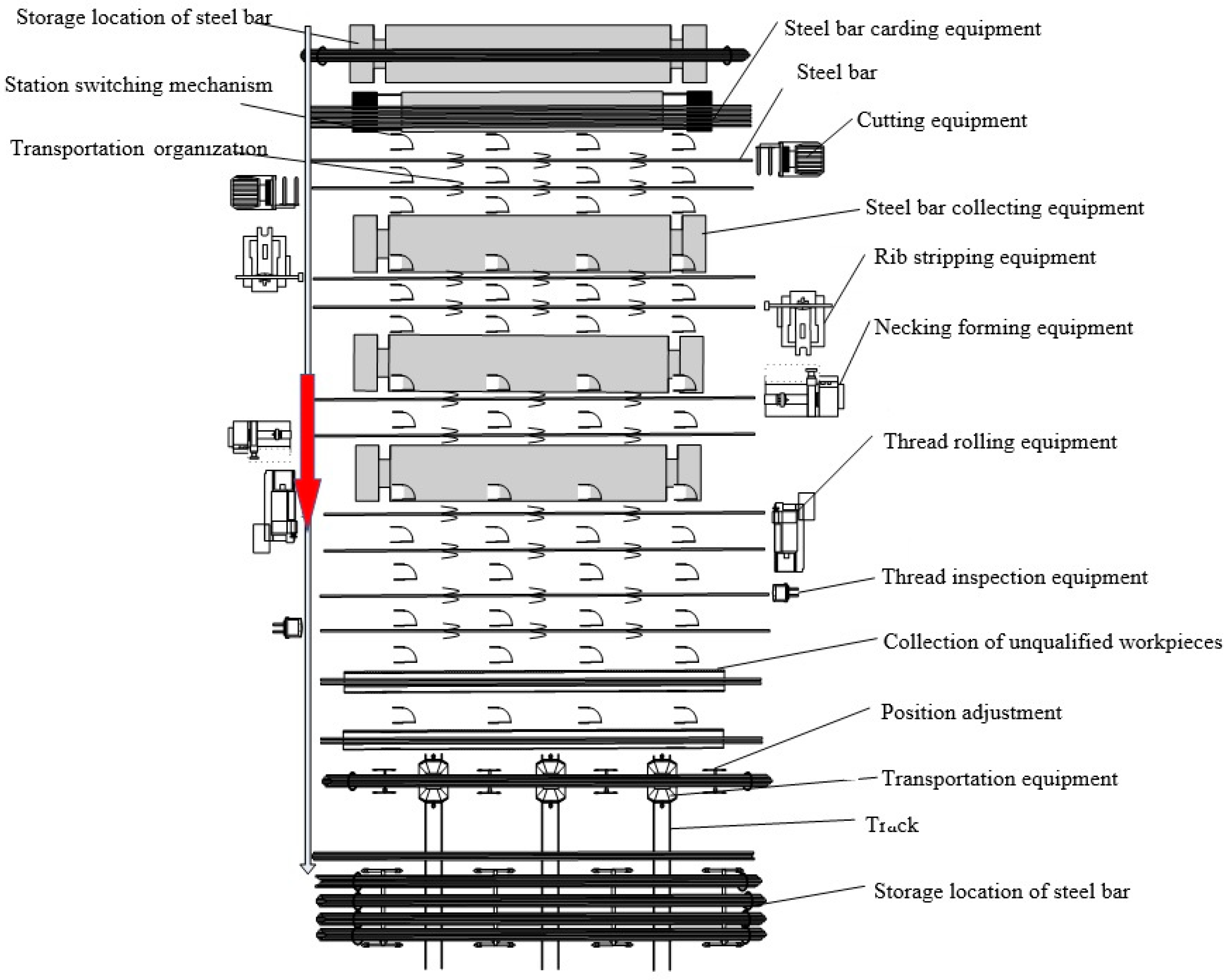
2.1. Forming Method of High-Strength Steel Bar Thread

The parameters of HRB500 high-strength hot-rolled ribbed steel bar are as follows. The nominal diameter of the thread is 40 mm. Inner radius of the thread is 38.7 ± 0.7 mm. Transverse rib is 2.9 mm. Height of longitudinal rib is 3.5 mm. Cross-rib width is 3.5 mm. Thread length is 60 mm.
For HRB500 high-strength steel bars, Figure 1 shows the technical process of processing proposed in this paper. Firstly, the composite tool is used to mill the end face of the steel bar. Then, the transverse rib and longitudinal rib of the steel bar are stripped, and chamfer on the end surface is carried out (Figure 1c). Finally, the thread is extruded after the necking process (Figure 1i). The method can effectively improve the connection strength and thread accuracy of the end.
Figure 2 shows layout of the HRB500 high-strength steel bars production line. The axial length of the HRB500 high-strength steel bars is 12 m. They are not suitable to be transported in a curved way. Therefore, a linear arrangement is adopted in this production line. The processing equipment of each station is installed on the left and right sides of the production line.

2.2. Processing Experiment

Figure 3 shows the test equipment. Using the rib stripping and chamfering equipment with a composite tool (Figure 3a), necking formation equipment (Figure 3b), and thread rolling equipment (Figure 3c), the face milling, rib stripping and chamfering of the 40 mm diameter steel bar end were carried out. The length of the thread to be processed is 60 mm, and the diameter of the workpiece is 40.7 mm. The diameter of the steel bar end is 38.90 mm after necking formation, and the pitch of the rolled thread is 1.5 mm.
To verify the feasibility of the processing technology of high-strength steel bar thread, six HRB500 high-strength steel bars were used for milling end face, rib stripping, chamfering, necking formation and thread rolling formation at room temperature. The outer diameter of the finished thread was measured and recorded. A screw-in test was performed using a standard threaded connecting sleeve. According to the requirements of work efficiency, the cutting speed was set to 300 r/min, 400 r/min, and 500 r/min, the feed per tooth was set to 0.12 mm/z, 0.15 mm/z, and 0.18 mm/z, and the cutting depth was set to 2 mm, 3 mm, and 4 mm. The high-strength steel bar was processed by modifying the set parameters, and the peak value was compared by the spin test of the force measuring wrench (Figure 3h). The final parameters are as follows: the rotational speed of composite tool was set to 400 r/min, the transverse feed speed was set to 360 mm/min, the milling depth was set to 3 mm, and the longitudinal feed speed was set to 180 mm/min. The necking die translational speed was 25 mm/s, the thread rolling wheel was 35 r/min, the thread rolling time was 6 s, the thread rolling wheel feed speed was 3 mm/s, and the rolling feed was 0.12 mm/r. After cutting, the end face of the steel bar was relatively smooth (Figure 3e) and most of the ribs of the steel bar were removed. The root diameter of the steel bar was not cut, which ensured the integrity of the metal fiber at the end of the steel bar. The end of the bar was chamfered. All remaining ribs were extruded and flattened by the necking die, and the end surface after extrusion was smooth. Due to the influence of metal flow, the length of the end is increased slightly. After necking, the steel bar was processed by the thread rolling wheel (Figure 3f). The thread tooth shape was relatively complete without obvious defects (Figure 3g), and it was tested with a standard threaded connecting sleeve for screw-in. Results demonstrate that the threaded steel bar was easily screwed into the standard connecting sleeve (Figure 3h), and that the threaded surface was good quality.
Figure 3i shows the dimensions of each group of bars after rib stripping. The dimensional variation range of each group is 40.50~40.80 mm (Figure 3d). The main reason for the deviation is the existence of transverse ribs and longitudinal ribs when the steel bar is clamped. As shown in Figure 3j, which displays dimension changes after necking formation, the simulated workpiece dimensions and the actual machined dimensions are within the dimensions required for the workpiece, and the workpiece dimensions before thread rolling meet the requirements (Figure 3d). After processing, the outer diameter of the thread is compared with the thread dimension of 6f accuracy class (the outer diameter of the thread is 39.719~39.955 mm, and the variation range pitch diameter is 38.831~38.981 mm). The variation range of the outer diameter of the thread machined by the processing technology in this study is 39.86~39.94 mm (Figure 3l), and the variation range of pitch diameter is 38.86~38.90 mm (Figure 3k). According to the result measured by thread plug gauge, the processed thread meets the dimensional accuracy requirements of Class I joints.

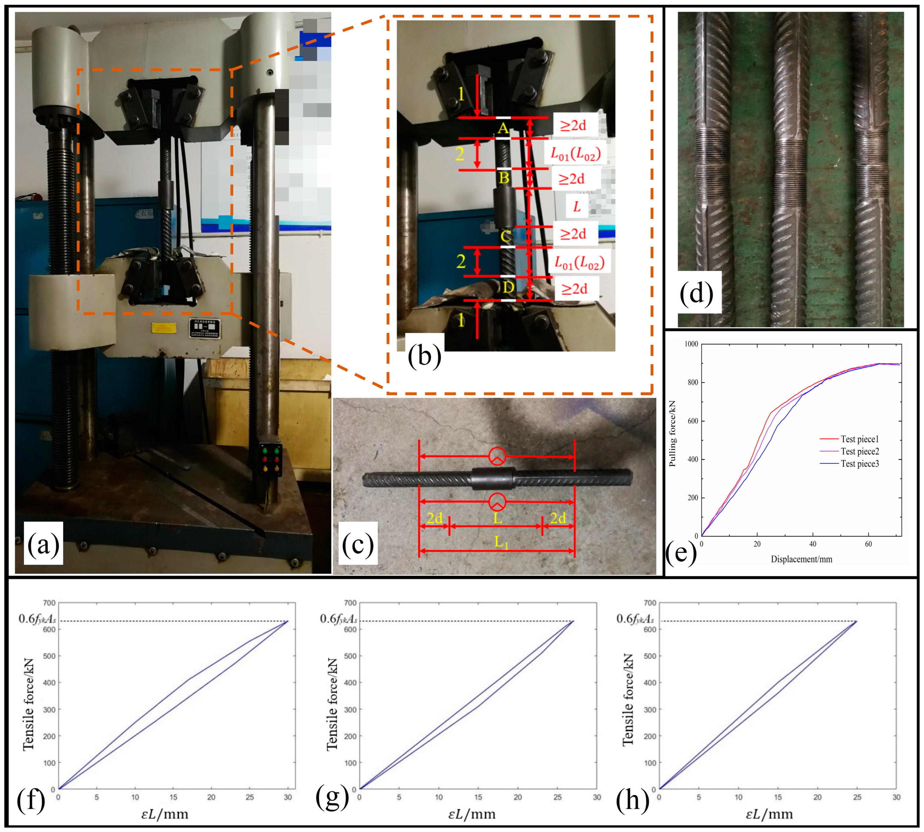
2.3. Mechanical Property Test

2.3.1. Test Method

Figure 4c shows the gauge distance and instrument arrangement for deformation measurement of the connecter. In the uniaxial tensile test (Figure 4a), the change in length of the steel bar is measured by the deformation measuring instrument. Two deformation measuring instruments are installed on both sides of the steel bar. After connecting the six processed steel bars by a connecting sleeve, they are divided into three groups and numbered separately. The ends of the bars to be connected should be tightened against each other, and the exposed thread length should be less than 2 times the pitch.
The uniaxial tensile residual deformation can be written as
L 1 = L + 4 d
where L1 is the gauge length of deformation measurement; L is the length of connecter; and d is the nominal diameter of steel bar.
Figure 4b shows the distribution of measuring points for total elongation. To measure the maximum total elongation Asgt and uniaxial tensile residual deformation u0, the steel bar surface is marked before the tensile test and changes in the length of the steel bar can be measured, as shown in Equation (2). Marking on both sides of the connection sleeve at a distance greater than 80 mm, and then marking again in the direction away from the sleeve, the distance between the two marked lines on the same side is greater than 100 mm. For the uniaxial tensile test, the load is loaded in the following way: firstly, from 0, loaded to 0.6 fyk (HRB500 high-strength steel bar with fyk of 500 MPa); then unloaded to 0 and the amount of residual deformation of the steel bar is measured; finally, loaded from 0 to the maximum tensile force.
If the necking of the connecter occurs at one end of the steel bar, the lengths L01 and L02 should be read at the other end of the steel bar. If the damage occurs at the connecting sleeve, the readings of both are taken as the average of the two ends, and the readings are calculated according to the following equation.
A s g t = [ L 02 L 01 L 01 + f 0 m s t E ] × 100
where L01 is the measured distance between A, B or C, D before loading; L02 is the measured distance between A, B or C, D after unloading; f m s t 0 is the stress of the steel bar when the connecter reaches the maximum force; and E is the theoretical elastic modulus of steel bar.

2.3.2. Results

Figure 4e shows the relationship between pulling force and displacement. By increasing axial load of the testing machine, the axial deformation of the three connecters increased. At the initial stage of tension, the axial deformation of the three specimens changed less, and after reaching 650 kN, the axial deformation of the connecters increased significantly in axial elongation rate. The main reason for this situation may be that the stress exceeded the yield limit of the connecters, resulting in elastic-plastic deformation. The tensile force provided by the test equipment causes the connecter to enter the yielding stage, so the curve is relatively flat. This means that the displacement of the connecter is more sensitive to changes in tensile force, and a small change in tensile force can cause a large displacement of the specimen. When the tensile force reaches 900 kN, the connecter has reached the strengthening stage.
As shown in Figure 4f–h, the test machine loaded the load to 628.3 kN and then started to unload; the stress on the steel bar did not reach its yield limit and it was in the elastic stage. Therefore, the deformation of the connecter decreased rapidly, as shown in Table 1. The residual deformations of the three groups of connecters were 0.08 mm, 0.11 mm, and 0.07 mm.
The strength requirement for Class I connecters is that the tensile strength of the steel bar connecters should be greater than or equal to 1.10 times the standard value of tensile strength of the connected steel bars. The standard value of 1.10 times tensile strength of HRB500 high-strength steel bar used in this study is 693 Mpa. The tensile strength of all three sets of connecters is greater than 693 Mpa, which meets the strength requirements of Class I connecters. For the performance of I connecters in deformation, the total elongation ratio is greater than 4.0%, and the residual deformation of bars with diameter greater than 32 mm is less than 0.14 mm. The maximum residual deformation of the three groups of connecters is 0.11 mm, and the minimum total elongation is 12.82%, which all meet the deformation performance requirements of I connecters.

3. Discussion

3.1. Effect of Cutting Parameters on Cutting Force

The finite element method (FEM) is an effective alternative to experiments and has been used in recent years to study the material response in machining in many fields [28]. To explore the influence of cutting parameters on cutting force in the process of threading machining using composite tools, a series of finite element simulations are carried out. According to Celis et al. [29], cutting force is likely to be directly or indirectly affected by controllable and uncontrollable factors, including cutting speed, cutting depth, cutting width, the material of workpiece, tool geometry, tool wear, and cutting temperature. Furthermore, workpiece quality, tool life, and energy consumption will be affected by the cutting force [30]. In the process of high-strength steel thread formation, we use the finite element method (FEM) to simulate the influence of relevant parameters on cutting force, including cutting speed, feed per tooth, and cutting depth.

3.1.1. Tool Cutting Model

The composite tool can finish three processes separately, which are milling end face, rib stripping, and chamfering of the steel bar (Figure 1c). To verify the rationality of the composite tool design, a simulation analysis is carried out (Figure 5n). The movement of the composite tool is set as follows: the rotational speed of the cutter is 400 r/min, the feed rate is 0.72 mm/r, the moving speed of the cutter is set to 4.8 mm/s, and the rotation angular speed of the cutter is 41.89 rad/s. As shown in Equation (3), a comprehensive analysis of the effect of strain and strain rate on the flow stress of the material leads to the following Johnson-Cook model.
σ = [ A + B ( ε P ) n ] [ 1 + C ln ε p · ε r p · ]
where A, B, n, and C are all fitting parameters; and ε P and ε p · are plastic strain and plastic strain rate respectively. According to the parameters of the Johnson-Cook constitutive model, A is 500 Mpa, B is 320 Mpa, the value of n is 0.28, the value of C is 0.0225, and the value of m is 1.06.

3.1.2. Cutting Form Analysis

The milling parameters are: milling depth, ap = 3 mm; feed per tooth, fz = 0.12 mm; and tool speed, n = 400 r/min.
According to the simulation results, it can be seen that the cutting process is divided into three stages. In the stage of plastic deformation (Figure 5a), the cutter begins to gradually approach the workpiece. The workpiece is squeezed by the cutter tip gradually. With the increasing of internal stress of the squeezed area, the workpiece is deformed. In the stage of shear slip (Figure 5b), the cutter continues to squeeze the workpiece. The force of the material element nodes of the workpiece continues to increase. After the stress exceeds its failure criterion, the squeezed element node is judged to be invalid. Then, the metal squeezed by the cutter falls off from the workpiece. The fallen metal slides along the cutting edge of the cutter. In the stage of chip formation (Figure 5c), the material separated by the cutter continuously flows out along the cutting edge and undergoes bending deformation, and then forms chips.

3.1.3. Cutting Force Analysis

The main sources of cutting force are the deformation resistance generated when the tool cuts into the workpiece, the friction between the cutter’s rake face and the chip, and the friction between the cutter’s flank face and the machined surface. Cutting force data collected in real time can help to monitor the condition of the cutting tool at any instant and predict abnormal tool failure [31,32]. In the initial stage, the workpiece is contacted and squeezed by the cutter, then elastic deformation occurs. Increasing the force, elastic deformation will be transformed into plastic deformation. In Figure 5d, the cutting force increases to the maximum value, and some cutting layers of metal are separated from the workpiece. Then, the cutting force decreases slightly and the stable cutting state is achieved. The cutting force in the Y direction always has the largest value, because it overcomes the deformation resistance of materials. The cutting force in the X direction is to overcome the friction between the cutter’s flank face and the machined surface.

3.1.4. Effect of Cutting Speed on Cutting Force

In the simulation of the effect of cutting speed on cutting force, the tool material is YT15, the cutting depth is ap = 3 mm, the feed per tooth is fz = 0.12 mm/z, and the spindle speed is set to 300 r/min (Figure 5e), 400 r/min (Figure 5f), and 500 r/min (Figure 5g). In the cutting process, increasing the rotational speed makes the chip deformation faster, and the work done per unit of cutting is increased. These energies are converted into cutting heat, causing serious local heat accumulation and increasing the cutting temperature. Therefore, cutting force is mainly affected by rotational speed through chip deformation and cutting temperature change. Cutting force is greatly affected by the change of rotational speed. At the beginning of cutting, the rotational speed is low, but the cutting force quickly reaches the maximum value. After that, with the increase of rotational speed, the cutting deformation speed is accelerated and chip deformation is reduced. Clearly, the cutting force has a downward trend in the middle stage. The reason is that, with an increase in cutting time, the cutting temperature is gradually increased, leading to the formation of chip buildup. Therefore, the actual rake angle of the turning tool is increased, and cutting deformation is further reduced. Later, when the cutting temperature is too high, metal micro-melting occurs on the surface where the chip contacts the front corner of the composite tool. This layer of micro-melted metal plays a special role in lubrication, and the cutting force is reduced again. Finally, the change of cutting force tends to be stable.

3.1.5. Effect of Feed Rate on Cutting Force

In the simulation of the influence of feed rate on cutting force, cutting depth is ap = 3 mm, spindle speed is n = 400 r/min, and feed rate per tooth is set to fz = 0.12 mm/z (Figure 5h), 0.15 mm/z (Figure 5i), and 0.18 mm/z (Figure 5j). The cutting force increases with the increase of feed rate. In the cutting process, by increasing the value of fz, the cutting volume of the cutter is increased, and the cutting force increases. The reason for this is that, with the increase of feed rate per tooth, the change frequency of cutting force is obviously increased and the change range is obviously enlarged. This phenomenon is due to the increase of the amount of chips to be cut during the tool rotation, resulting in the increase in cutting force. It can be seen from the results that the cutting force in the X direction is obviously increased, because the resistance of the chip to tool movement is also increased with the increase in chip volume.

3.1.6. Effect of Cutting Depth on Cutting Force

In the simulation, feed rate per tooth is fz = 0.15 mm/z, spindle speed is n = 400 r/min, and cutting depth is ap = 2 mm (Figure 5k), 3 mm (Figure 5l), and 4 mm (Figure 5m). Because of the increase in cutting depth, the deformation resistance of the material is increased, and the cutting forces in all directions are boosted. At the beginning of cutting, the cutting force instantly increases to the maximum value, then decreases slightly, and finally tends to be stable. Clearly, with increasing cutting depth, the change frequency of cutting force is increased, and the tool life is reduced. With the increase in cutting depth, the cutting force is rapidly increased, resulting in the rapid increase of cutting temperature. This phenomenon causes the metal micro-melting to occur on the surface where the chip contacts the rake angle of the composite tool, and the friction force on the surface is reduced. Therefore, with increasing time, the cutting force in the Z direction has a downward trend [33]. Through the finite element analysis of the influence of relevant parameters on cutting force in the cutting process, it is concluded that the optimal parameters are similar to the results obtained by the spin-in experiment.

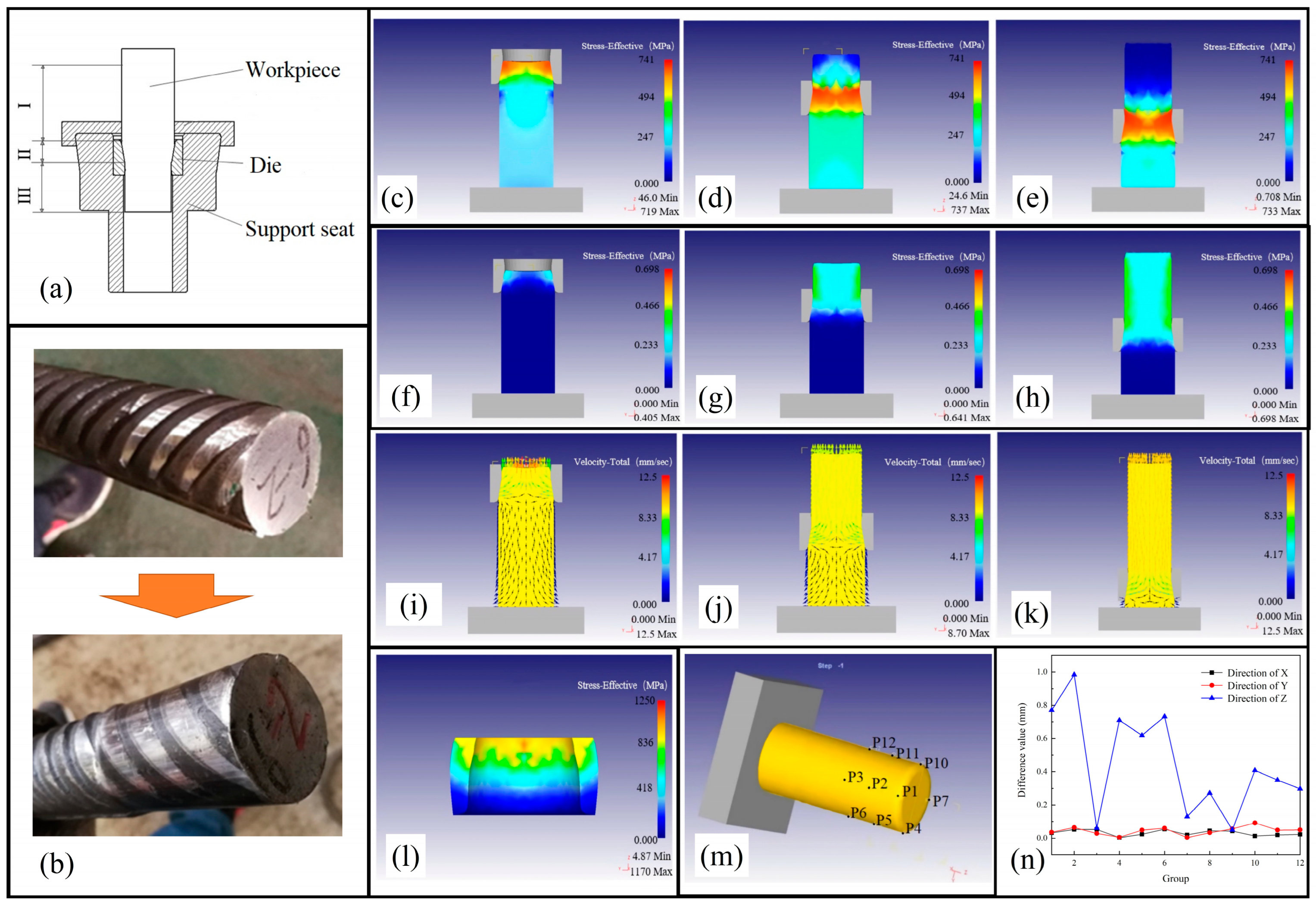
3.2. Influence of Necking Process on High-Strength Steel Bar Processing

3.2.1. Open-Die Cold Extrusion

The end face of the HRB500 high-strength steel bar is milled by the composite tool. The transverse rib and longitudinal rib of the steel bar are stripped. The chamfer in the end surface is carried out. Then, the thread is extruded after necking formation process. Figure 6a shows a diagram of the necking formation process. Extrusion is a cold processing technology. Under extrusion, the metal is forced to flow through the die orifice at high pressure, resulting in reducing the section. The method is widely used in primary material processing and secondary material processing industries [34]. After the steel bar is clamped, the die of the necking formation process moves along the axis direction. Under the extrusion of the die, the metal at the end of the steel bar flows in the opposite direction. The radial dimension of the steel bar’s end is decreased, increasing metal density and improving its hardness, as shown in Equations (4) and (5).
An unit extrusion force, p, is expressed in Equation (4).
p = F A 0
where F represents the total extrusion force; and A0 is the sectional area of the extruded workpiece. As shown in Equation (5), the degree of deformation ε is the change rate of the sectional area of before and after blank deformation after the extrusion is completed. The limit degree of deformation ε max is on the premise that the blank part does not fail after extrusion forming. The blank part produces the limit value of the degree of deformation ε .
ε = A 0 A 1 A 0 × 100 %
where A0 is the sectional area of the blank before extrusion; and A1 is the sectional area of the blank after extrusion.

3.2.2. Numerical Analysis of Cold Extrusion Simulation

The open-die cold extrusion process has geometrical problems and non-linear material contact problems. It is difficult to use theoretical formulae to calculate the relevant parameters accurately. Methods of simulation can provide visual observation of the completed machining, determining the feasibility of the process. Graphite lubrication is usually used in the process of necking formation, the friction factor is set to 0.08, and the friction type is set to shear friction. In the initial extrusion stage (Figure 6c), the end of the steel bar enters the cavity of the die and it is extruded by the inner wall of the die. The stress of the metal entering the cavity is the largest, while the metal not entering the cavity is also extruded. In the middle stage (Figure 6d), the middle part of the steel bar enters the cavity of the die, and the stress of the steel bar completing extrusion at the upper of the die is 0. The stress of the blank located in the cavity has a maximum value, and the stress of the steel bar not entering the cavity of the die is gradually increased by the downward extrusion pressure. In the final stage (Figure 6e), the stress of the steel bar that has completed extrusion is restored to 0. Figure 6f–h show the equivalent strain distribution of the workpiece during the necking formation process. Figure 6i–k show the metal flow velocity distribution of the workpiece during the necking formation process. When the workpiece enters the cavity of the die, the metal starts to flow upward. The flow direction of the metal inside the cavity of the die is opposite to the direction of the die movement. The metal flows upwards, resulting in the decreased radial size of the workpiece. In the whole extrusion, the outer layer of the workpiece is contacted with the cavity of the die firstly; the outer layer flows upward, then followed by the inner layer. The maximum value of the outer layer is 0.48 Mpa, and the equivalent strain of the workpiece is decreased from the outside to the inside.

3.2.3. Analysis of Springback

In the necking formation process of steel bar, elastic deformation of the bar and die occur simultaneously. After extrusion is completed, the extruded workpiece usually springs back because the extruded metal contains elastic strain [35]. Necking formation is an important part of the high-strength steel bar threading process. The forming dimensions should meet the requirements of the rolling process. To ensure the accuracy of the high-strength steel bar threads, the elastic deformation generated in the necking formation process must be studied and analyzed.
The residual stress inside the extrusion mainly comes from the continuous extrusion of the steel bar by the die. When the die is divorced from the end of the steel bar, the extrusion pressure on the end of the steel bar disappears suddenly, while the end of the steel bar is still under stress (Figure 6l). The extruded part of the steel bar is reverted elastically by the residual stress. The workpiece is set as an elastoplastic body, the die is set as an elastomer, and the remaining parameters are set as above. Using the point tracking function, the nodal coordinates of specific locations on the end of the steel bar before and after the springback were recorded, and then the springback law was investigated based on the recorded changes in nodal coordinates (Figure 6m). At the same section of the steel bar, three sections were selected, and four points were recorded per section uniformly.
Figure 6n shows the coordinate difference value before and after springback of workpiece. The maximum springback values are 0.05 mm, 0.06 mm, and 0.98 mm along the X direction, Y direction, and Z direction, respectively. The changes in radial direction are caused by the elastic expansion of the die and the residual stress present at the end of the steel bar. The sectional area of the steel bar end decreases and the axial dimension increases.

3.3. Influence of Rolling Formation Process on Steel Bar Processing

The thread cold extrusion process is a chipless processing method based on the theory of metal plasticity. It is a method of processing metal materials by extruding them, so that they are plastically deformed to obtain a specific shape. The processing of rolling formation is the last step of the HRB500 high-strength steel bar processing technology. The selection of reasonable rolling parameters is the basis to ensure the smooth rolling process. To determine the optimum processing parameters, the mechanical properties of the workpiece and the dimensional elements of the thread need to be fully considered when selecting the roll forming parameters.

3.3.1. Rolling Force

Rolling force is the force that forces the workpiece to deform plastically and squeeze out the threads during the roll forming process. It is one of the key parameters to ensure that roll forming can be completed successfully, as shown in Equation (6). Rolling force can be calculated by
E = 250 P H B 4 δ + Z P ( 1 2 K + 0.95 ) L F
where E is the rolling force; P is the pitch of the workpiece; HB is the material hardness of the workpiece; δ is the percentage elongation of the workpiece material; K is the number of rolling wheels; L is the length of the thread of the workpiece; F is the correction factor of the rolling force, F = 1 for 60 degree triangular thread, F = 1.5 for semi-circular thread, F = 2 for rectangular thread; and Z is the material of the workpiece, Z = 0.1~0.5 for carbon steel, Z = 0.5~1.0 for low alloy steel, Z = 1~2 for high-strength alloy steel, Z = 2~5 for special steel, such as stainless steel, copper alloy steel, etc. The pitch of the workpiece is 1.5 mm, the hardness of the workpiece is 388~477 kgf/mm2, the percentage elongation of the workpiece material is 15%, the thread length of the workpiece is 60 mm, the correction factor for rolling force is F = 1, the workpiece material Z is 0.5, and the calculated rolling force is 200.6 kN.

3.3.2. Rolling Speed

The rolling speed refers to the linear speed of the roller, including rotating speed of thread roller and radial feed speed. The rolling speed affects the deformation degree and deformation speed of the rolling wheel extrusion workpiece during rolling formation, and then determines the quality of the processed thread.
The ideal rolling speed can be calculated by Equation (7):
v = | ω | D 2 = | ω 0 | d 1 2
where D is the outer diameter of the roller; w is Angular speed of thread roller; w0 is the angular speed of the rolled workpiece; and d1 is the inner diameter of the thread.
The relative sliding between the roller and the workpiece is inevitable and always exists in the whole rolling process. In the actual rolling formation, the speed of the workpiece driven by the roller is lower than that in Equation (7). Therefore, the rolling speed v0 of the workpiece can be obtained by adding a slip coefficient in Equation (8).
v 0 = v η = | ω | D 2 η
where η is the slip coefficient, usually a value of 0.85~0.95.
The selection of rolling speed v0 in Equation (8) takes into account the mechanical properties, overall dimensions, and material properties of the part. High rolling speed will reduce the deformation time of the workpiece, resulting in insufficient plastic deformation of the workpiece and low quality of the thread. When the rolling speed is chosen to be too low, the amount of pressure applied to the thread roller will increase, increasing rolling pressure. Table 2 shows the recommended value of rolling speed. The diameter of the thread roller is 180 mm and the thread pitch is 1.5 mm. The rolling speed can be set to 20 m/min. The speed of the thread roller is 35 r/min.

3.3.3. Rolling Feed Rate

The rolling feed rate is the radial feed rate of the thread rolling wheel relative to the workpiece within one circle. The factors considered in the selection of the rolling feed rate include the life of the thread rolling wheel, production efficiency, the material of workpiece, and other factors. When the chosen rolling feed rate is too large, the temperature between the thread rolling wheel and the workpiece will increase. The loss of the thread rolling wheel is exacerbated, resulting in poor thread roundness. Thus, the accuracy of the threads processed is reduced. When the chosen rolling feed is too small, the rolling efficiency will decrease greatly, as shown in Equations (9) and (10).
According to the relevant information, the rolling feed rate can be expressed as
S = f 2 D d 0 D + d 0 ( 1 + p E )
where f is the friction coefficient; D is the diameter of the thread rolling wheel; d0 is the diameter of the workpiece; p is the unit rolling force, for straight thread, p = (2.5~3)σT, σT is the flow limit of the material; and E is the elastic modulus of material.
The radial movement speed of the thread rolling wheel can be calculated as:
v T = v S d 0
where v is the linear speed of the thread rolling wheel; S is the radial feed rate; and d0 is the diameter of the thread rolling wheel.
The reason for the thread surface metal falling off is that the radial feed rate and linear speed of the thread rolling wheel are too large, resulting in the radial movement speed of the wire roller increasing, the surface metal being displaced tangentially along the wire roller, and a large degree of deformation. It was calculated that the strength limit of HRB500 high-strength steel bar is greater than 539.3 Mpa and the pitch of the rolled thread is 1.5 mm, so the rolling feed rate is set to 0.12 mm/r and the feed speed is set to 3 mm/s.

4. Conclusions

In this study, the process of threading high-strength steel bars, which includes face milling, rib removal, chamfering, necking, and thread rolling, was investigated.
(1)
By analyzing the influence of different cutting parameters on cutting force, a conclusion was drawn that the cutting force is increased with the increase of cutting depth, feed rate, and spindle speed. Cutting depth had the greatest influence on the cutting force, followed by the feed rate per tooth, and the spindle speed had the smallest influence.
(2)
Through the finite element analysis of the necking formation process, the loading calculation of the steel bar necking formation was carried out, and the stress and deformation of the whole forming process of the workpiece were simulated and analyzed. Through springback analysis, it was concluded that the maximum springback values were 0.05 mm, 0.06 mm, and 0.98 along the X direction, Y direction, and Z direction, respectively.
(3)
The main parameters in rolling formation, including extrusion pressure, rolling speed, rolling feed rate, and rolling time, were analyzed to provide a theoretical basis for processing experiment.
(4)
The thread dimensions and thread quality of the workpiece processed by this process were inspected, and the results showed that the completed threads met the accuracy requirements and quality requirements of Class I joints. The thread processing process can complete the processing of large diameter high-strength steel bar threads, and the finished steel bar thread dimensions, strength performance, and deformation performance meet the requirements of nuclear power construction.

Author Contributions

Conceptualization, H.N., J.Y. and J.Z.; methodology, H.N., J.Y. and S.Y.; software, J.Y. and S.Y.; validation, J.Y. and S.Y.; formal analysis, J.Y. and S.Y.; investigation, W.Z.; resources, J.Y. and S.Y.; data curation, S.Y.; writing—original draft preparation, H.N., J.Y. and S.Y.; writing—review and editing, J.Y. and H.Y.; visualization, H.Y.; supervision, J.Z. All authors have read and agreed to the published version of the manuscript.

Funding

This research was funded by Natural Science Foundation of Hebei Province (Grant No. E2021208004), and Science and Technology Project of Hebei Education Department (Grant No. QN2021061).

Data Availability Statement

Not applicable.

Conflicts of Interest

The authors declare no conflict of interest.

References

  1. Zhang, J.; Cai, R.; Li, C.; Liu, X. Seismic behavior of high-strength concrete columns reinforced with high-strength steel bars. Eng. Ures 2020, 218, 110861. [Google Scholar] [CrossRef]
  2. Li, X.; Zhang, J.; Cao, W. Hysteretic behavior of high-strength concrete shear walls with high-strength steel bars: Experimental study and modelling. Eng. Ures 2020, 214, 110600. [Google Scholar] [CrossRef]
  3. Guo, Z.; Ma, Y.; Wang, L.; Zhang, J.; Harik, I.E. Corrosion fatigue crack propagation mechanism of high-strength steel bar in various environments. J. Mater. Civ. Eng. 2020, 32, 04020115. [Google Scholar] [CrossRef]
  4. Ding, Y.; Wu, D.; Su, J.; Li, Z.-X.; Zong, L.; Feng, K. Experimental and numerical investigations on seismic performance of RC bridge piers considering buckling and low-cycle fatigue of high-strength steel bars. Eng. Struct. 2021, 227, 111464. [Google Scholar] [CrossRef]
  5. Zhang, J.; Zhao, Y.; Li, X.; Li, Y.; Dong, H. Experimental study on seismic performance of recycled aggregate concrete shear wall with high-strength steel bars. Structures 2021, 33, 1457–1472. [Google Scholar] [CrossRef]
  6. Gao, D.; Gu, Z.; Tang, J.; Zhang, C. Fatigue performance and stress range modeling of SFRC beams with high-strength steel bars. Eng. Struct. 2020, 216, 110706. [Google Scholar] [CrossRef]
  7. Lu, P.-Y.; Liu, Y.; Wu, H.-J.; Liu, G.; Meng, X.; Xu, Y. Fatigue Performance of Microalloyed high-strength rebar and analysis of fracture mechanism. J. Iron Steel Res. Int. 2015, 22, 1149–1155. [Google Scholar] [CrossRef]
  8. Liu, H.; Wang, L.; Sun, J.; Liu, W.; Wang, Z. Corrosion Resistance of Niobium Microalloyed HRB500 Mild Steel Rebar in the Alkaline Concrete Pore Solution. Int. J. Electrochem. Sci. 2020, 15, 6596–6604. [Google Scholar] [CrossRef]
  9. Gao, Y.; Ko, J.H.; Lee, H.P. 3D Eulerian Finite Element Modelling of End Milling. In Proceedings of the CIRP International Conference on High Performance Cutting, Budapest, Hungary, 25–27 June 2018; Volume 77, pp. 159–162. [Google Scholar]
  10. Wang, S.; Li, J.; He, C.; Xie, Z. A 3D analytical model for residual stress in flank milling process. Int. J. Adv. Manuf. Technol. 2019, 104, 3545–3565. [Google Scholar] [CrossRef]
  11. Otalora-Ortega, H.; Osoro, P.A.; Arriola, P.J.A. Analytical modeling of the uncut chip geometry to predict cutting forces in orthogonal centric turn-milling operations. Int. J. Mach. Tools Manuf. 2019, 144, 103428. [Google Scholar] [CrossRef]
  12. Ducobu, F.; Rivière-Lorphèvre, E.; Filippi, E. Finite element modelling of 3D orthogonal cutting experimental tests with the Coupled Eulerian-Lagrangian (CEL) formulation. Finite Elem. Anal. Des. 2017, 134, 27–40. [Google Scholar] [CrossRef]
  13. Malekian, M.; Mostofa, M.; Park, S.; Jun, M. Modeling of minimum uncut chip thickness in micro machining of aluminum. J. Mater. Process. Technol. 2011, 212, 553–559. [Google Scholar] [CrossRef]
  14. Thepsonthi, T.; Özel, T. Experimental and finite element simulation based investigations on micro-milling Ti-6Al-4V titanium alloy: Effects of cBN coating on tool wear. J. Mater. Process. Technol. 2012, 213, 532–542. [Google Scholar] [CrossRef]
  15. Wojciechowski, S.; Maruda, R.W.; Krolczyk, G.M.; Niesłony, P. Application of signal to noise ratio and grey relational analysis to minimize forces and vibrations during precise ball end milling. Precis. Eng. 2018, 51, 582–596. [Google Scholar] [CrossRef]
  16. Urbikain, G.P. Modelling of static and dynamic milling forces in inclined operations with circle-segment end mills. Precis. Eng. 2019, 56, 123–135. [Google Scholar]
  17. Wan, M.; Li, S.-E.; Yuan, H.; Zhang, W.-H. Cutting force modelling in machining of fiber-reinforced polymer matrix composites (PMCs): A review. Compos. Part A Appl. Sci. Manuf. 2019, 117, 34–55. [Google Scholar] [CrossRef]
  18. Zhang, D.W.; Zhang, C.; Tian, C.; Zhao, S.D. Forming characteristic of thread cold rolling process with round dies. Int. J. Adv. Manuf. Technol. 2022, 120, 2503–2515. [Google Scholar] [CrossRef]
  19. Kramer, P.; Groche, P. Defect detection in thread rolling processes—Experimental study and numerical investigation of driving parameters. Int. J. Mach. Tools Manuf. 2018, 129, 27–36. [Google Scholar] [CrossRef]
  20. Ţălu, Ş.; Sağlam, H.; Kus, R.; Bramowicz, M.; Kulesza, S. Experimental investigations of threads surface integrity manufactured by cutting insert and with internal thread rolling head. CIRP J. Manuf. Sci. Technol. 2020, 31, 334–341. [Google Scholar] [CrossRef]
  21. Zhang, S.; Fan, S.; Wang, Q.; Zhao, S.; Zhu, Q. Deformation characteristics of self-infeed rolling process for thread shaft. Int. J. Adv. Manuf. Technol. 2019, 103, 2941–2951. [Google Scholar] [CrossRef]
  22. Zhang, S.; Fan, S.; Zhang, P.; Zhu, Q.; Zhao, S. The formation mechanism of protrusion of long thread by axial self-infeed rolling process. Proc. Inst. Mech. Eng. Part B J. Eng. Manuf. 2020, 234, 1302–1310. [Google Scholar] [CrossRef]
  23. Aktas, S.; Kisioglu, Y. Effects of thread rolling processing parameters on mechanical properties and microstructures of high-strength bolts. Mater. Test. 2020, 62, 1017–1024. [Google Scholar] [CrossRef]
  24. Chen, X.; Hou, H.; Wu, L.; Huang, T.; Mei, M.; Zhao, Y. Research on metal flow law and strengthening mechanism of cold extrusion internal thread. J. Braz. Soc. Mech. Sci. Eng. 2022, 44, 109. [Google Scholar] [CrossRef]
  25. Heinzel, C.; Müller, S. Characteristics of the Combined Rolling and Extrusion Process. Key Eng. Mater. 2022, 926, 401–408. [Google Scholar] [CrossRef]
  26. He, Y.; Li, L.; Wan, M.; Xue, H. Three-dimensional finite element simulations of milling carbon/epoxy composites. Compos. Struct. 2021, 282, 115037. [Google Scholar] [CrossRef]
  27. Naser, M.Z.; Hawileh, R.A.; Abdalla, J. Modeling strategies of finite element simulation of reinforced concrete beams strengthened with FRP: A review. J. Compos. Sci. 2021, 5, 19. [Google Scholar] [CrossRef]
  28. Cui, Q.; Liu, T.; Li, X.; Zhao, L.; Wu, Q.; Wang, X.; Song, K.; Ge, D. Validation of the mechano-bactericidal mechanism of nanostructured surfaces with finite element simulation. Colloids Surf. B Biointerfaces 2021, 206, 111929. [Google Scholar] [CrossRef] [PubMed]
  29. Celis, P.; Vazquez, E.; Soria-Hernández, C.G.; Bargnani, D.; Rodriguez, C.A.; Ceretti, E.; García-López, E. Evaluation of Ball End Micromilling for Ti6Al4V ELI Microneedles Using a Nanoadditive Under MQL Condition. Int. J. Precis. Eng. Manuf. Technol. 2021, 9, 1231–1246. [Google Scholar] [CrossRef]
  30. Chen, Y.; Lu, J.; Deng, Q.; Ma, J.; Liao, X. Modeling study of milling force considering tool runout at different types of radial cutting depth. J. Manuf. Process. 2022, 76, 486–503. [Google Scholar] [CrossRef]
  31. Li, S.; Zhu, K. In-situ tool wear area evaluation in micro milling with considering the influence of cutting force. Mech. Syst. Signal Process. 2021, 161, 107971. [Google Scholar] [CrossRef]
  32. Gao, G.; Xia, Z.; Su, T.; Xiang, D.; Zhao, B. Cutting force model of longitudinal-torsional ultrasonic-assisted milling Ti-6Al-4V based on tool flank wear. J. Mater. Process. Technol. 2021, 291, 117042. [Google Scholar] [CrossRef]
  33. Yan, H.; Deng, F.; Qin, Z.; Zhu, J.; Chang, H.; Niu, H. Effects of Grinding Parameters on the Processing Temperature, Crack Propagation and Residual Stress in Silicon Nitride Ceramics. Micromachines 2023, 14, 666. [Google Scholar] [CrossRef]
  34. Hou, H.; Xin, C.H.E.N.; Yongqiang, Z.H.A.O.; Yayin, H.E.; Changqian, W.A.N.G. The influence of the bottom hole of cold extruding internal thread on thread quality. Mechanics 2021, 27, 335–341. [Google Scholar] [CrossRef]
  35. Mechtcherine, V.; Bos, F.P.; Perrot, A.; da Silva, W.L.; Nerella, V.N.; Fataei, S.; Wolfs, R.J.; Sonebi, M.; Roussel, N. Extrusion-based additive manufacturing with cement-based materials-production steps, processes, and their underlying physics: A review. Cem. Concr. Res. 2020, 132, 106037. [Google Scholar] [CrossRef]
Figure 1. Technical process of machining. (a) Workpiece section diagram. (b) External surface of steel bar. (c) Machining process of the composite tool. (d) Composite tool model. (e) Process of face milling. (f) Process of rib stripping and chamfering. (g) Process of necking formation. (h) Process of thread rolling. (i) Changes process of steel bar.
Processes 11 01223 g001
Figure 2. Layout of the HRB500 high-strength steel bars production line.
Processes 11 01223 g002
Figure 3. Experimental process. (a) Rib stripping and chamfering equipment. (b) Necking formation machine. (c) Thread rolling machine. (d) Diameter to be measured. (D1—Dimensions of steel bar end after stripping ribs. D2—Dimensions changes after necking formation. D3—Thread outer diameter after rolling.) (e) Experimental results of workpieces by composite cutting tool. (f) Experimental results of workpieces after necking formation. (g) Experimental results of workpieces after thread rolling formation. (h) Experimental results of workpieces for screw-in test. (i) Dimensions of steel bar end after stripping ribs. (j) Dimension changes after necking formation. (k) Changes of pitch diameter of rolled thread. (l) Changes of thread outer diameter after rolling.
Processes 11 01223 g003
Figure 4. Mechanical property test. (a) Tensile machine. (b) Distribution of measuring points for total elongation (1—Clamping area; 2—Test area). (c) Gauge distance and instrument arrangement for deformation measurement of connecter. (d) Three groups of specimens after processing. (e) The curve of pulling force with displacement. (fh) Tensile displacement curves of three groups of specimens after the first unloading.
Processes 11 01223 g004
Figure 5. E×ploring the influence of cutting parameters on cutting force. (ac) Simulation of cutting process: stages of (a) plastic deformation, (b) shear slip, and (c) chip formation. (d) Curve of cutting force variation. (eg) Cutting force in different directions: the speed of (e) 300 r/min, (f) 400 r/min, and (g) 500 r/min. (hj) Cutting force in different directions: the feed rate per tooth of (h) 0.12 mm/z, (i) 0.15 mm/z, and (j) 0.18 mm/z. (km) Cutting force in the Z direction. The depth of cutting is (k) 2 mm, (l) 3 mm, and (m) 4 mm. (n) Composite tool cutting ribs of surface.
Processes 11 01223 g005
Figure 6. E×ploring the influence of necking formation process on high-strength steel bar processing by finite element analysis (FEA). (a) Diagram of the necking formation process (III—deformed section, II—plastic deformation, I—not deformed). (b) Changes before and after necking formation. (ce) The equivalent stress distribution: stages of (c) initial extrusion, (d) stable extrusion, and (e) final extrusion. (fh) Equivalent strain distribution: stages of (f) initial extrusion, (g) stable extrusion, and (h) final extrusion. (ik) Metal flow velocity distribution: stages of (i) initial extrusion, (j) stable extrusion, and (k) final extrusion. (l) Equivalent stress distribution diagram of the die. (m) Surface point set of extrusion parts. (n) Coordinate difference value before and after springback of workpiece.
Processes 11 01223 g006
Table 1. Joint performance parameters.
NumberTensile Strength (Mpa)Residual Deformation
u0 (mm)
Maximum Total Elongation
Astg (%)
01716.350.0812.82
02716.440.1114.87
03716.550.0714.90
Table 2. Recommended value of rolling speed.
Screw Pitch
mm
Aluminum Alloy and Carbon Steel
(m·min−1)
Alloy Steel and Carbon Steel
(m·min−1)
Refractory and Titanium Alloys
(m·min−1)
0.35, 0.5, 0.6, 0.7302520
0.8, 1, 1.25, 1.5302015
1.75, 2301512
Disclaimer/Publisher’s Note: The statements, opinions and data contained in all publications are solely those of the individual author(s) and contributor(s) and not of MDPI and/or the editor(s). MDPI and/or the editor(s) disclaim responsibility for any injury to people or property resulting from any ideas, methods, instructions or products referred to in the content.

