Article

A Novel Continuous Roll-Forming Process of Elastomer Molds

Department of Mechanical and Energy Engineering, National Chiayi University, Chiayi 60004, Taiwan
*
Author to whom correspondence should be addressed.
Processes 2023, 11(3), 931; https://doi.org/10.3390/pr11030931
Submission received: 30 November 2022 / Revised: 9 March 2023 / Accepted: 17 March 2023 / Published: 18 March 2023
(This article belongs to the Special Issue Advances in Innovative Engineering Materials and Processes (II))

Abstract

:
This study proposed a novel continuous roll-forming process of elastomer molds, which can control the deformation of the mold using the rolling belt stack combination method. This study analyzed various rolling belt combinations, assembled the system based on simulation and experimental data according to the deformation requirement design, and obtained a controllable microstructure mold rolling belt with tensile deformation. Mold thickness and microstructure size are key microstructure mold deformation parameters. This study designed and assembled a controllable microstructure mold rolling belt-type imprint molding system and conducted a series of experiments. The impact and application of different experimental system operation procedures and fabrication methods of the auxetic structure rolling belt on replication molding were analyzed. The innovative controllable microstructure mold rolling belt-type imprint replication molding technique proposed in this study had a stable and controllable mold deformation mechanism. It can control and replicate molding.

1. Introduction

The micro/nano imprint molding technique is often applied to the technological manufacturing of micro patterns or micro components [1,2,3,4,5,6,7,8,9,10,11,12,13,14,15,16,17,18,19,20]. The UV-curing step and flash imprint lithography (SFIL) technique [21,22,23] can be applied to a quick, low-temperature, and low-pressure manufacturing process. It can be applied to curved surfaces [24]. For UV-curing SFIL, imprint molds can be made using flexible materials to facilitate the processing of curved surfaces. However, flexible molds may occasionally have problems with microstructure distortion and deformation. As a result, there are two research directions. The first research direction is improving the microstructure distortion and deformation problem. Li et al. [24] proposed a combination of microstructural rigid light-curable film and polydimethylsiloxane (PDMS) film to prevent the deformation of microstructure patterns during imprint on curved surfaces. The second direction is applying a special processing method to deform flexible molds. Xia et al. [25] proposed applying mechanical deformation or the swelling of PDMS to change the imprint patterns of PDMS molds. However, regarding mechanical deformation, the accuracy of patterns is limited by the deformation system. Regarding swelling of PDMS, the process is complicated, and the degree of deformation is limited. Pokroy et al. [26] conducted mechanical deformation of PDMS molds with a cilia array structure and obtained a customized cilia structure with a high depth-to-width ratio. Liu et al. [27] used PDMS molds with different thicknesses to change microstructure patterns by leveraging different degrees of deformation under mechanical deformation. According to the literature review, the flexible molds’ deformation control imprint technique has preliminarily matured. However, most studies focus on the step imprint technique [28,29,30,31,32,33,34,35]. This study aims to develop an innovative UV-curing rolling belt-type SFIL, where most studies focus on the step imprint technique microstructure pattern customization function. The deformation control method was designed with the mold rolling belt and auxetics to obtain a continuous and large-area SFIL with real-time pattern control.

2. Design of Mold Deformation and Simulation Analysis of Auxetic Structure

2.1. Design of Mold Deformation System

Most studies on flexible molds with mechanical deformation controlled the degree of deformation by installing several clamps around a mold. However, clamps could not be installed around the rolling mold for the rolling belt-type imprint technique proposed in this study. This study introduced auxetics as the material for making the deformation drive rolling belt stacked with a PDMS mold rolling belt to form a controllable microstructure mold rolling belt (Figure 1). Protrusions were set on both sides for fitting with the specially designed mold rolling belt. The trusswork on both sides of the mold rolling belt was for fitting and even distribution of the tensile force of auxetics and to assist the auxetics in the deformation of the PDMS mold. The trusswork of the mold rolling belt and the PDMS material of the microstructure replication area had different properties. Specially designed elastic rings were installed at three locations to prevent warping of the upper and lower rolling belts during deformation, as shown in Figure 2.

2.2. Selection of Auxetics and Their Structures and Simulation Analysis of Mold Rolling Belt

2.2.1. Selection of Materials and Setting of Parameters of Simulation Materials

This study used ANSYS software to analyze the transverse stress of auxetics and the mold rolling belt. It numerically designed size parameters. Regarding auxetics, a thermoplastic elastomer material was used. This material is often used for 3D printing. In the analysis, the material was set with a modulus of elasticity of 22.41477 Mpa, Poisson’s ratio of 0.499, and tensile strength of 3.26885 Mpa. The material of the trusswork on both sides of the mold rolling belt was PDMS (A:B = 5:1). For analysis, the material was set as follows: modulus of elasticity 1.93171 Mpa, Poisson’s ratio 0.499, and tensile strength 0.52859 Mpa. In addition, the material of the microstructure replication area in the middle of the mold rolling belt was PDMS (A:B = 20:1). For analysis, the material was set as follows: modulus of elasticity 0.38577 Mpa, Poisson’s ratio 0.499, and tensile strength: 0.10743 Mpa. The longitudinal stress of the auxetics and mold rolling belt was set to 0.05–0.1. The transverse stress of the two was limited to simulate the condition of the rolling belt at Poisson’s ratio = 0 or −1, i.e., to simulate the movement of the actual microstructure mold under uniaxial tensile deformation or uniform expansion deformation.

2.2.2. Design and Selection of Auxetic Structure

Regarding auxetic structure, this study proposed a Y-shaped rigid rotational auxetic structure. The limit of Poisson’s ratio of the Y-shaped rigid rotational auxetic structure cannot be less than −1. Therefore, this study analyzed the transverse stress at Poisson’s ratio = 0. For this structure, the design of Poisson’s ratio was affected by the fracture length (l)–distance between unit structures (L0) ratio (l/L0). The larger the ratio, the smaller the Poisson’s ratio, as shown in Figure 3. This study adopted four designs (l/L0 = 0.5, 0.6, 0.7, and 0.8) for the Y-shaped rigid rotational auxetic structure.

2.2.3. Simulation Analysis of the Auxetic Structure and Mechanical Property Testing

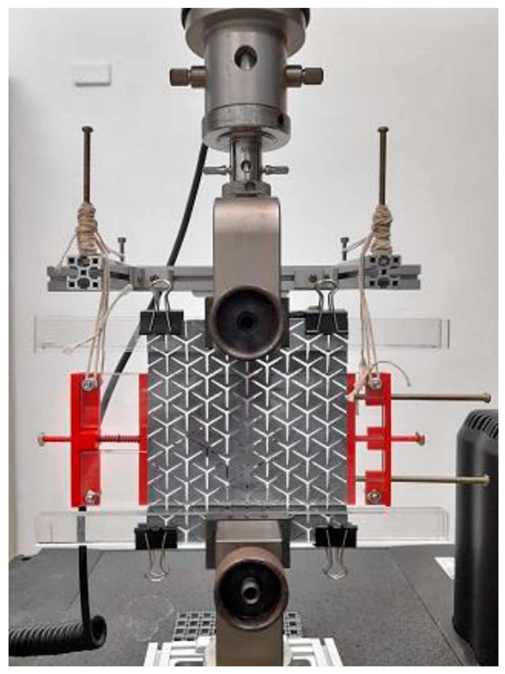
In this study, for the Y-shaped rigid rotational auxetic structure and mechanical property testing, during Instron instrument tensile testing (ISO-527 typs standard), we obtained the detailed mechanical properties data of the Y-shaped rigid rotational auxetic structure, as shown in Figure 4.
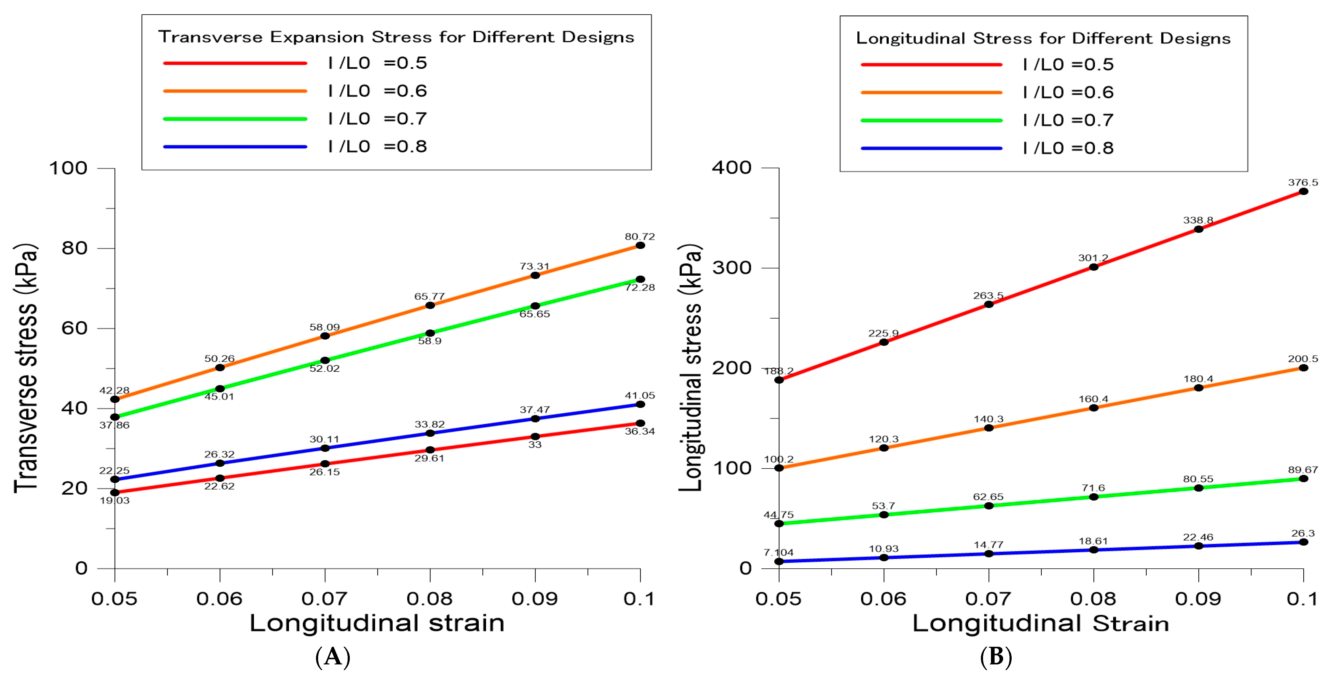
Based on the analysis, the Y-shaped rigid rotational auxetic structure was under the maximum transverse expansion stress (40.7–77.7 kPa) and had an excessive longitudinal tensile stress requirement (100.2–200.5 kPa) at l/L0 = 0.6. In such a case, the machine would be too stressed to stretch the rolling belt. At l/L0 = 0.8, the transverse expansion stress (18.8–38.9 kPa) was smaller than the design parameter. However, the longitudinal tensile stress requirement (7.1–26.3 kPa) significantly decreased, as shown in Figure 5. Regarding the Y-shaped rigid rotational auxetic structure, the testing and simulation results with relation to vertical and horizontal tension stress and tension strain are shown in Figure 6. The transverse expansion force can be changed by the thickness of the auxetic structure. Therefore, it can be concluded from the above experiment that the auxetic structure design with a smaller Poisson’s ratio would obtain the same transverse expansion force under a smaller longitudinal tensile force.

3. Experimental Methods

3.1. Design and Development of Imprint System Machine

3.1.1. Design, Simulation, and Selection of Mold Rolling Belt Trusswork

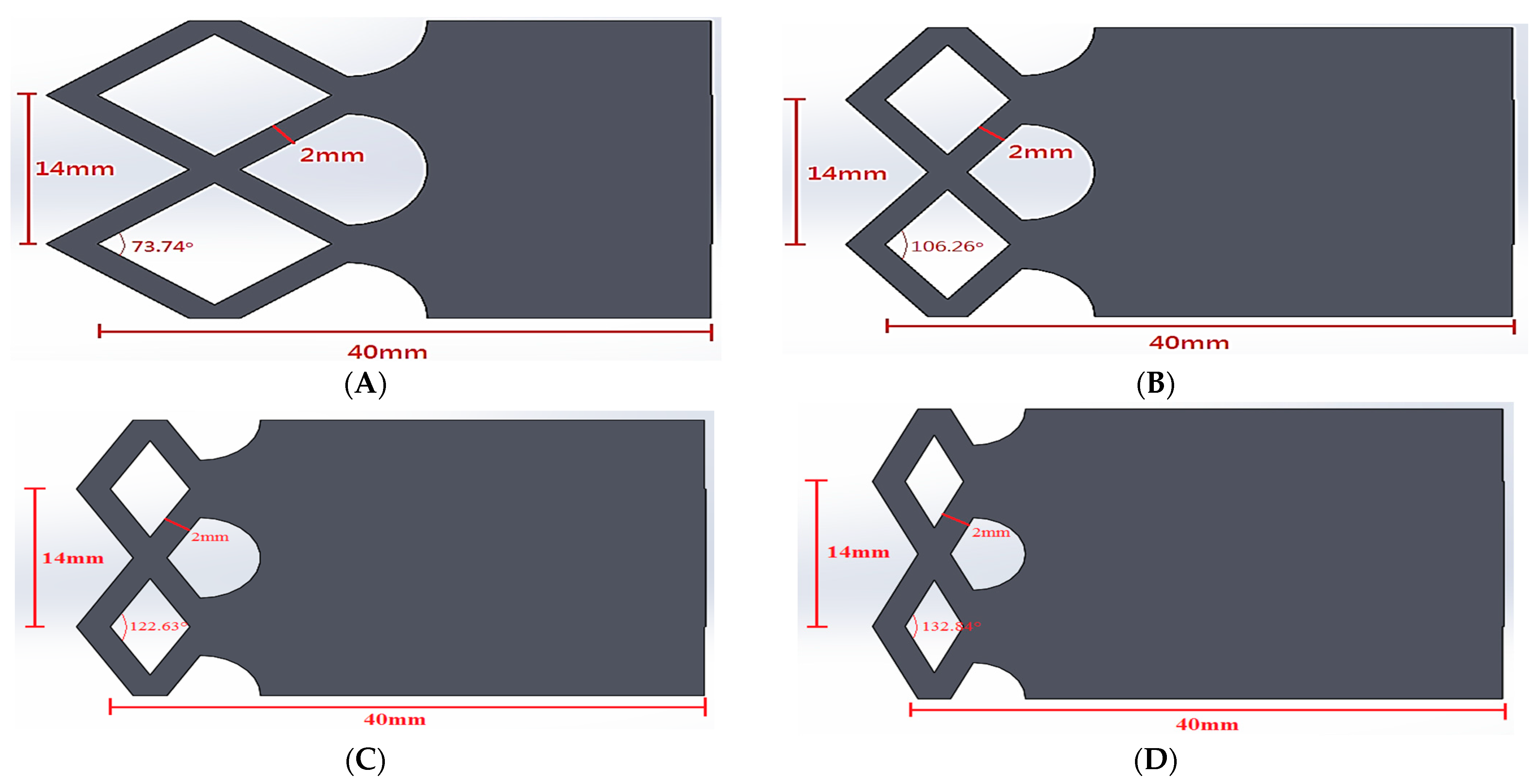
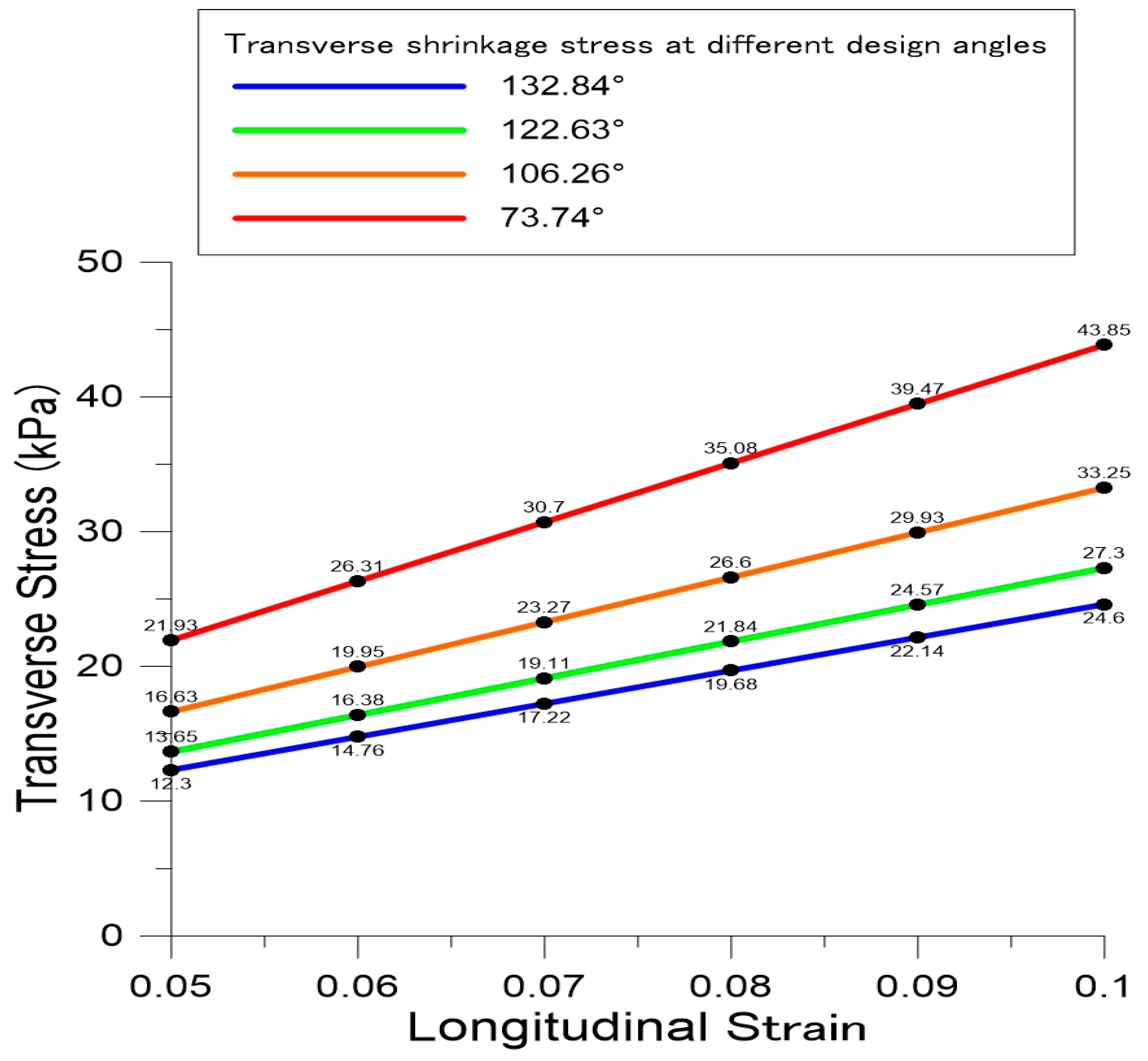
This study proposed two trusswork designs and observed the change in the transverse contraction stress of the mold rolling belt trusswork through four trusswork angles, as shown in Figure 7 and Figure 8. The design shown in Figure 7 was for observing the effect of trusswork angle on transverse contraction stress. The design shown in Figure 8 was for observing the effect of the trusswork aspect ratio on transverse contraction stress. The four trusswork angles are 73.74°, 106.26°, 122.63°, and 132.84°. Based on the analysis, the smaller the trusswork angle, the greater the transverse contraction stress, as shown in Figure 9. The length–thickness ratio of the trusswork support will significantly affect the transverse contraction stress (Figure 10). The trusswork angle of 73.74° provided the best result. The support length–thickness ratio design can be used to control the transverse contraction stress of the trusswork. Table 1 lists the transverse contraction stress data at various trusswork support aspect ratios designed for the Y-shaped rigid rotational auxetic structure. This study analyzed the microstructure replication area in the middle of the mold rolling belt. It prepared the transverse contraction stress simulation data table and the simulation data trendline table (Table 2). Furthermore, the parameter design combination of the auxetics, the mold rolling belt trusswork, and the microstructure replication area was identified through the transverse force value. By doing so, the microstructure mold used in the actual machine can have uniaxial tensile deformation or uniform expansion deformation movement.

3.1.2. Design, Erection, and Actuating Program of System Machine

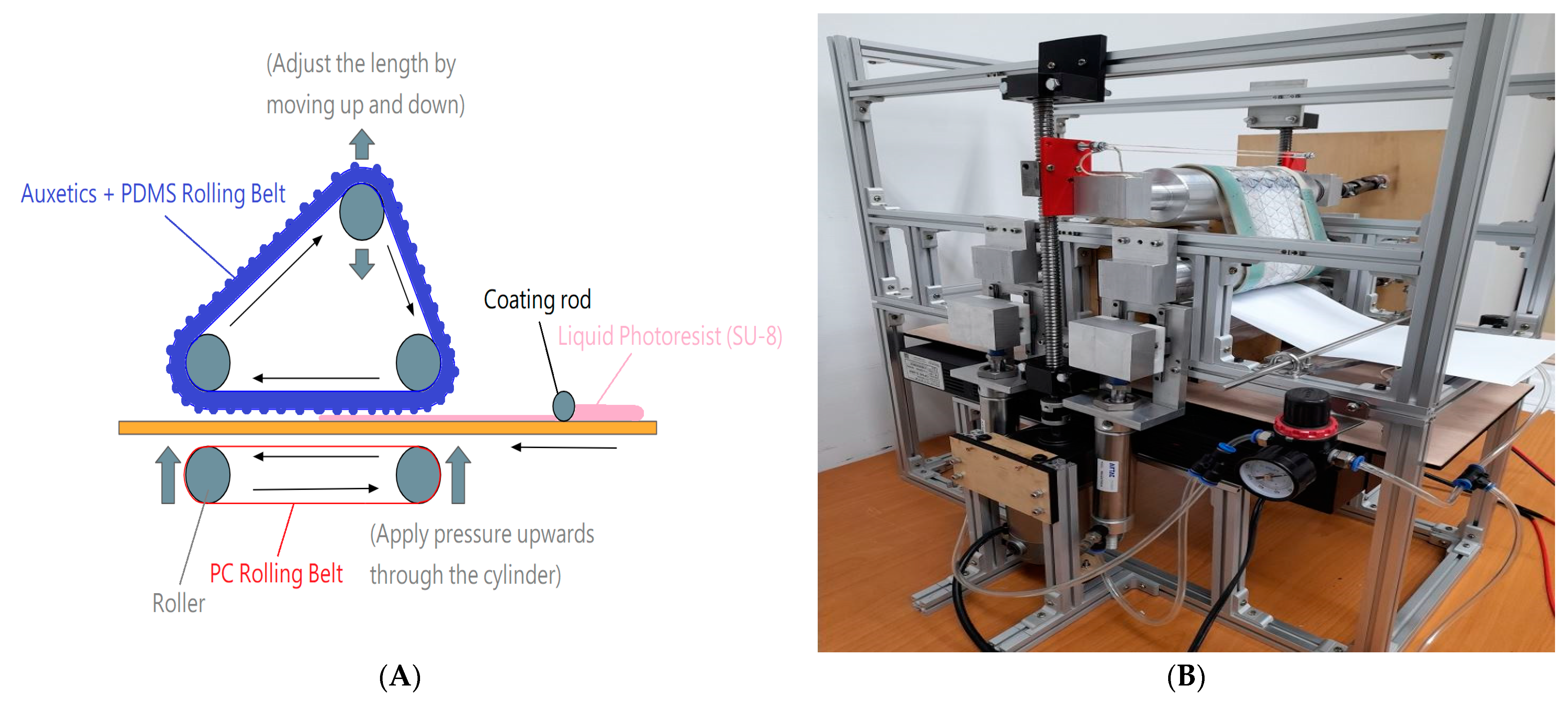
In terms of the design and erection of the machine proposed in this study, the controllable microstructure mold rolling belt was wound around two upper fixed rollers and one tensile control roller. The tensile control roller moves up and down through the screws on both sides to control the tensile force of the microstructure mold rolling belt. The auxetic structure rolling belt trusswork and the flexible mold rolling belt trusswork cause a transverse expansion movement on the microstructure transfer print area in the middle of the flexible mold rolling belt. In addition, the lower transparent PE film was used as the conveyor rolling belt. The UV light shined onto the imprint area from the bottom. The source of imprint pressure was the upward movement of two lower rollers through the pneumatic cylinder. In addition, a coating bar was fixed at the entrance of the imprint coil stock of the machine to preliminarily scrape excessive photoresist to facilitate subsequent imprint actions, as shown in Figure 11. Figure 12 shows the rolling uniformity testing of pressure-sensitive film (FUJIFILM’s Ultra Low Pressure, 0.2~0.6 MPa).

3.2. Microstructure Size and Selection of Photoresist

Perforated array aluminum sheets were fabricated by a laser to make the machine replicate convex array structures (diameter: 200 μm, 250 μm, 300 μm, and 400 μm). PC plastic sheets were hot imprinted. Thin PC sheets that were transfer printed into convex array structures were used to fabricate PDMS rolling belts with a concave array structure through the mold filling of PDMS. Convex array structures of corresponding sizes were obtained through the UV-curing imprint process of the PDMS rolling belts with a concave array structure. In addition, the photoresist used in the UV-curing imprint process was SU8 UV-curing photoresist with an excellent pattern transfer print rate, moisture resistance, and acid and alkali resistance.

3.3. Imprint Replication Molding Procedure

The replication molding procedure in this study was as follows. (1) The controllable microstructure mold rolling belts were stretched to the preset length during the idling operation. (2) After stretching the rolling belts to the preset length, the idling operation was continued to enable the uniform deformation of the controllable microstructure mold rolling belts. (3) The UV-curing imprint process was implemented. (4) The imprint result was obtained.

4. Results and Discussion

4.1. Simulation Analysis and Discussion on Microstructure Replication Molding

This part used a hemispherical concave structure array for simulation analysis. The longitudinal tensile stress was set to 0.05 and 0.1 for uniaxial tensile and uniform expansion deformation, respectively. The material was set as the same as the material of the microstructure replication area of the PDMS rolling belt. The modulus of elasticity, Poisson’s ratio, and tensile strength were 0.38577 Mpa, 0.499, and 0.10743 Mpa, respectively.

4.1.1. Effect of the Thickness of the PDMS Rolling Belt on the Deformation Degree of the Microstructure

A hemispherical concave structure with a diameter of 100 μm was used for simulation analysis on PDMS rolling belts with thicknesses of 1 mm, 2 mm, and 3 mm. Based on simulations under both uniaxial tensile deformation and uniform expansion deformation, the thickness of the PDMS rolling belt had no impact on the deformation degree of the microstructure. The transverse force between the auxetic structure rolling belt and the PDMS mold rolling belt could be controlled through the thickness without changing the degree of deformation on the microstructure (Table 3 and Table 4).

4.1.2. Effect of Microstructure Size on the Deformation Degree

Uniaxial tensile deformation and uniform expansion deformation were implemented with/at diameters of 100 μm, 150 μm, 200 μm, 250 μm, 300 μm, and 400 μm and longitudinal tensile stresses of 0.05 and 0.1. A smaller size of the hemispherical concave structure would lead to a higher degree of pattern deformation (Table 5, Table 6, Table 7 and Table 8). To change the pattern of a concave microstructure of a minimum size, only a moderate degree of tensile deformation of the PDMS mold rolling belt carried by the structure was required. In addition, the degree of pattern deformation of the microstructure and the degree of expansion between locations were different.

4.2. Discussion on the Study of Replication Molding

In this study, a concave microstructure with a diameter of 300 μm was processed through the UV-curing rolling belt-type imprint molding technique. During the process, the auxetic structure rolling belt parameters were designed with l/L0 being 0.8 and thickness being 2 mm.

4.2.1. Y-Shaped Rigid Rotational Auxetic Structure—Effect of Truss Structure Thickness and PDMS Mold Rolling Belt Thickness

The parameters of truss structure and the PDMS mold rolling belt were designed with a thickness of 0.5 mm. The PDMS mold rolling belt trusswork parameters were designed at an angle of 73.74° and support thickness of 5 mm. Table 9 shows the experimental results.
The average replication rates (truss structure thickness 0.5 mm and PDMS mold rolling belt thickness 0.5 mm) are 91.67% (diameter = 200 µm), 95.83% (diameter = 300 µm), and 95.33% (diameter = 400 µm).
The parameters of truss structure and the PDMS mold rolling belt were designed with a thickness of 1.5 mm. The PDMS mold rolling belt trusswork parameters were designed at an angle of 73.74° and support thickness of 5 mm. Table 10 shows the experimental results.
The average replication rates (truss structure thickness 1.5 mm and PDMS mold rolling belt thickness 1.5 mm) are 96% (diameter = 200 µm) and 90.67% (diameter = 400 µm). Furthermore, the PDMS mold rolling belt trusswork parameters were designed at an angle of 73.74° and support thickness of 5 mm. A longitudinal stress of 0.05 was exerted on the entire controllable microstructure mold rolling belt. If the imprint result showed a longitudinal stress of 0.05 and a transverse stress of 0, resulting from uniaxial tensile deformation, this paper suggests that the causes of this result are as follows. On the one hand, elastic rings limit the transverse deformation during the deformation. This can be addressed by improving the machine operation process. On the other hand, the mechanical properties of the auxetic structure rolling belt differed slightly from the data in the simulation analysis. In this experiment, the auxetic structure rolling belt was 3D printed, and the wire rod stack method would affect the physical properties of a 3D-printed object. As a result, the mechanical properties differed slightly from the simulation.

4.2.2. Effect of Poisson’s Ration

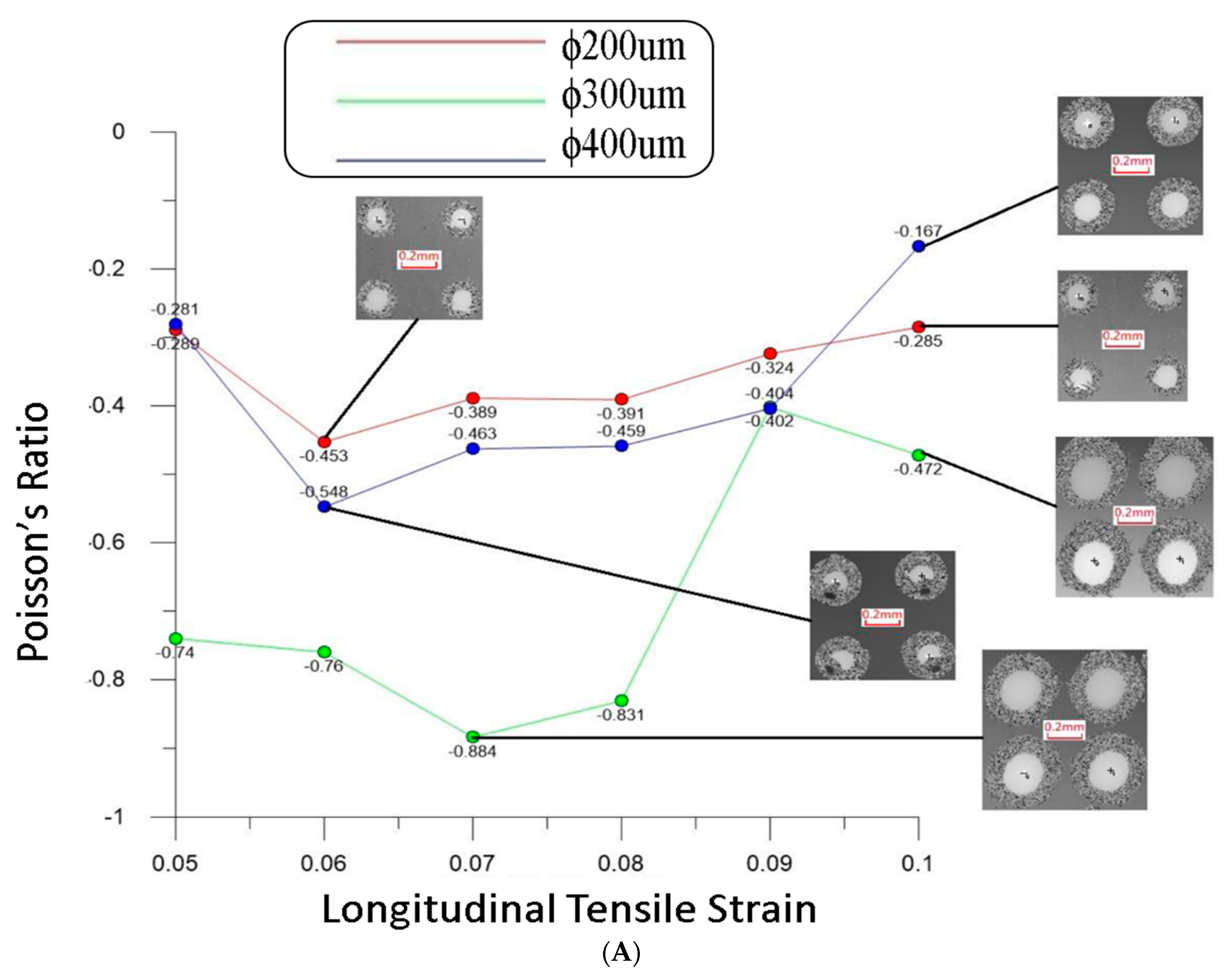
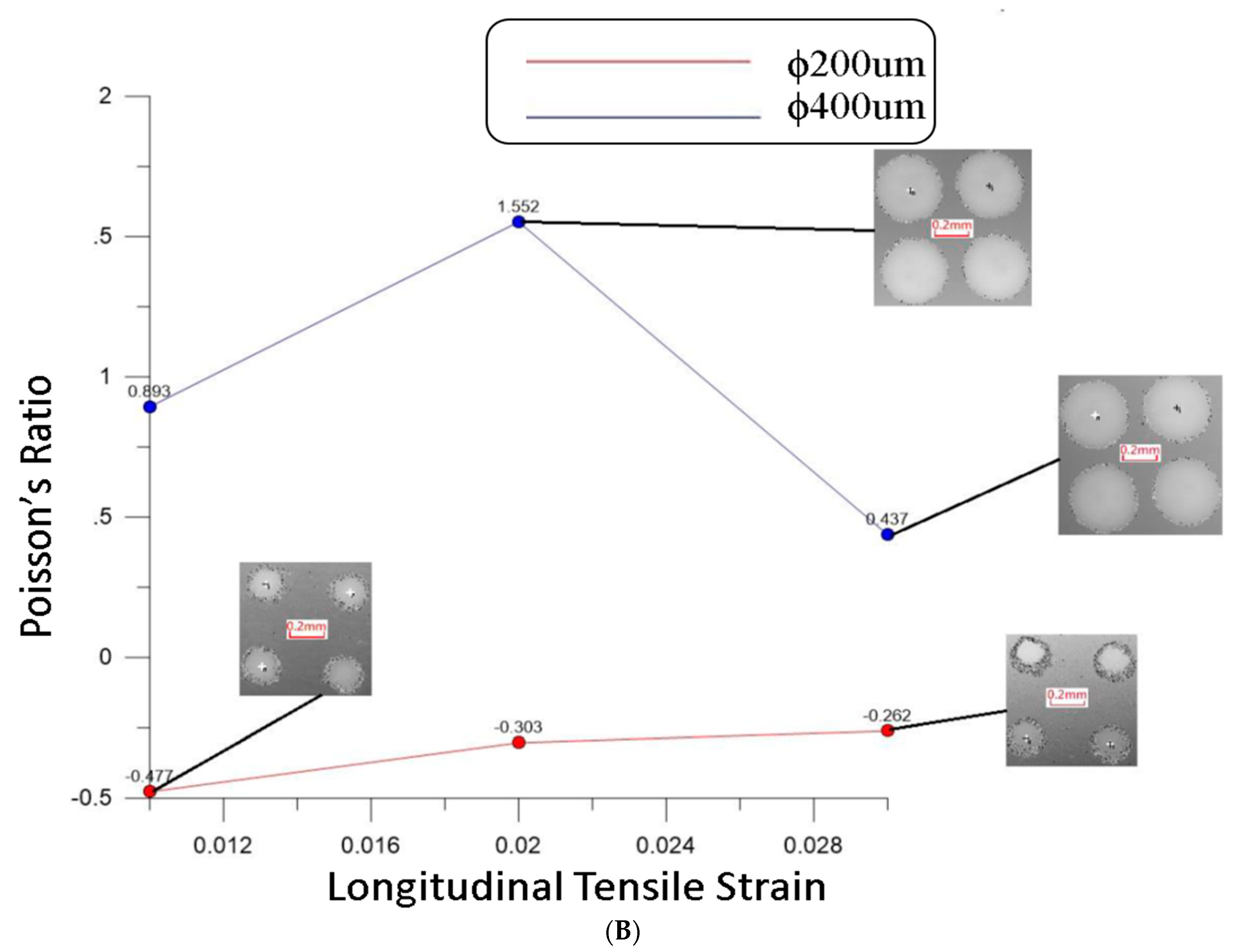
Figure 13 shows the Poisson’s ratio distributions of different truss structure thicknesses and PDMS mold rolling belt thicknesses. The innovative controllable microstructure mold rolling belt-type imprint replication molding technique proposed in this study had a stable and controllable mold deformation mechanism. It can control and replicate molding.

5. Conclusions

The novel continuous roll-forming process of elastomer molds proposed in this study utilized the rolling belt stack combination method. This study used different rolling belt combinations for analysis. It designed and assembled a controllable microstructure mold rolling belt with tensile deformation as the microstructure deformation control method. Based on the analysis, the thickness of the microstructure carrier in the rolling belt deformation had no impact on the deformation movement of the microstructure; the Y-shaped rigid rotational auxetic structure was under the maximum transverse expansion stress (40.7~77.7 kPa) and had an excessive longitudinal tensile stress requirement (100.2~200.5 kPa) at l/L0 = 0.6. The four trusswork angles are 73.74°, 106.26°, 122.63°, and 132.84°. Based on the analysis, the smaller the trusswork angle, the greater the transverse contraction stress. In this study, uniaxial tensile deformation and uniform expansion deformation were implemented with/at diameters of 100 μm, 150 μm, 200 μm, 250 μm, 300 μm, and 400 μm, and the microstructure size affected the degree of pattern deformation of the microstructure. A smaller size would lead to a higher degree of deformation. The pattern control of the microstructure would be affected by the stress of macro deformation and the microstructure size. Therefore, the location and pattern controls of the microstructure needed to be further checked to achieve a stable imprint. In this study, for a Y-shaped rigid rotational auxetic structure (the auxetic structure rolling belt parameters were designed with l/L0 being 0.8 and thickness being 2 mm), the parameters of truss structure and the PDMS mold rolling belt were designed with a thickness of 0.5 mm and 1.5 mm, and the PDMS mold rolling belt trusswork parameters were designed at an angle of 73.74° and support thickness of 5 mm. The average replication rates were 91.67% (diameter = 200 µm), 95.83% (diameter = 300 µm), 95.33% (diameter = 400 µm), 91.67% (diameter = 200 µm), 95.83% (diameter = 300 µm), and 95.33% (diameter = 400 µm). This study proposed a novel continuous roll-forming process of elastomer molds, which can control the deformation of the mold using the rolling belt stack combination method. The molding technique proposed in this study had a stable and controllable mold deformation mechanism. It could control and replicate molding through the precise control of the machine operation process and the fabrication of the auxetic structure rolling belt.

Author Contributions

Conceptualization, Y.-Y.C. and Y.-J.W.; methodology, Y.-Y.C. and Y.-J.W.; Formal analysis, Y.-Y.C. and Y.-J.W.; software, Y.-Y.C.; data curation, Y.-Y.C.; supervision, Y.-J.W.; funding acquisition, Y.-J.W.; project administration, Y.-J.W.; writing—review and editing, Y.-Y.C. and Y.-J.W. All authors have read and agreed to the published version of the manuscript.

Funding

This research was partially supported by the Ministry of Science and Technology (Series No. MOST 109-2221-E-415-005, MOST 110-2221-E-415-001, and MOST 111-2221-E-415-009) of Taiwan, ROC.

Data Availability Statement

Not applicable.

Acknowledgments

The authors gratefully acknowledge the financial support provided to this study by the Ministry of Science and Technology of Taiwan, ROC.

Conflicts of Interest

The authors declare no conflict of interest.

References

  1. Mpupa, A.; Dinc, M.; Mizaikoff, B.; Nomngongo, P. Exploration of a Molecularly Imprinted Polymer (MIPs) as an Adsorbent for the Enrichment of Trenbolone in Water. Processes 2021, 9, 186. [Google Scholar] [CrossRef]
  2. Zheng, R.; Jia, H.; Abualigah, L.; Liu, Q.; Wang, S. Deep Ensemble of Slime Mold Algorithm and Arithmetic Optimization Algorithm for Global Optimization. Processes 2021, 9, 1774. [Google Scholar] [CrossRef]
  3. Wolska, J.; Jalilnejad Falizi, N. Membrane Emulsification Process as a Method for Obtaining Molecularly Imprinted Polymers. Polymers 2021, 13, 2830. [Google Scholar] [CrossRef]
  4. Bender, M.; Otto, M.; Hadam, B.; Vratzov, B.; Spangenberg, B.; Kurz, H. Fabrication of nanostructures using a UV-based imprint technique. Microelectron. Eng. 2000, 53, 233–236. [Google Scholar] [CrossRef]
  5. Weng, Y.-J. Forming of Dynamic Microstructure of Flexible Polymer. Materials 2019, 12, 3332. [Google Scholar] [CrossRef] [Green Version]
  6. Lei, Z.; Su, W. Mold Level Predict of Continuous Casting Using Hybrid EMD-SVR-GA Algorithm. Processes 2019, 7, 177. [Google Scholar] [CrossRef] [Green Version]
  7. Roeder, M.; Guenther, T.; Zimmermann, A. Review on Fabrication Technologies for Optical Mold Inserts. Micromachines 2019, 10, 233. [Google Scholar] [CrossRef] [Green Version]
  8. Hasanah, A.N.; Safitri, N.; Zulfa, A.; Neli, N.; Rahayu, D. Factors Affecting Preparation of Molecularly Imprinted Polymer and Methods on Finding Template-Monomer Interaction as the Key of Selective Properties of the Materials. Molecules 2021, 26, 5612. [Google Scholar] [CrossRef]
  9. Meshalkin, V.P.; Belyakov, A.V. Methods Used for the Compaction and Molding of Ceramic Matrix Composites Reinforced with Carbon Nanotubes. Processes 2020, 8, 1004. [Google Scholar] [CrossRef]
  10. Weng, Y.-J.; Huang, J.-C.; Chen, Y.-Y.; Hsu, S.-T.; Zhang, Z.-R. A Study on the Dynamic Forming Mechanism Development of the Negative Poisson’s Ratio Elastomer Molds—Plate to Plate (P2P) Forming Process. Polymers 2021, 13, 3255. [Google Scholar] [CrossRef]
  11. Tahir, U.; Kim, J.I.; Javeed, S.; Khaliq, A.; Kim, J.-H.; Kim, D.-I.; Jeong, M.Y. Process Optimization for Manufacturing Functional Nanosurfaces by Roll-to-Roll Nanoimprint Lithography. Nanomaterials 2022, 12, 480. [Google Scholar] [CrossRef] [PubMed]
  12. Lim, S.H.; Ly, N.H.; Lee, J.A.; Kim, J.E.; La, S.-W.; Huong, V.T.; Tran, T.-G.; Ho, N.T.; Noh, S.M.; Son, S.J.; et al. Nanopatterned Polymer Molds Using Anodized Aluminum Templates for Anti-Reflective Coatings. Polymers 2021, 13, 3333. [Google Scholar] [CrossRef]
  13. Asgar, M.A.; Kim, J.; Haq, M.R.; Kim, T.; Kim, S.M. A Comprehensive Review of Micro/Nano Precision Glass Molding Molds and Their Fabrication Methods. Micromachines 2021, 12, 812. [Google Scholar] [CrossRef] [PubMed]
  14. Weng, Y.-J.; Lee, H.-J. Large-area roll printing and replication forming with curvature control of microlens array structures. Microsyst. Technol. 2021, 27, 3437–3445. [Google Scholar] [CrossRef]
  15. Shi, Y.; Jiang, Z.; Cao, J.; Ehmann, K.F. Texturing of metallic surfaces for superhydrophobicity by water jet guided laser micro-machining. Appl. Surf. Sci. 2020, 500, 144286. [Google Scholar] [CrossRef]
  16. Lee, Y.-C.; Leeghim, H.; Lee, C.-Y. Micropatterning of Metal-Grid Micro Electro Mechanical Systems (MEMS) Sensor for Crack Detection Using Electrohydrodynamic Printing System. J. Nanosci. Nanotechnol. 2020, 20, 4385–4389. [Google Scholar] [CrossRef] [PubMed]
  17. Li, Y.; Hong, M. Parallel Laser Micro/Nano-Processing for Functional Device Fabrication. Laser Photon- Rev. 2020, 14, 1900062. [Google Scholar] [CrossRef]
  18. Shahapurkar, K.; Venkatesh, C.; Tirth, V.; Manivannan, C.; Alarifi, I.M.; Soudagar, M.E.M.; El-Shafay, A.S. Influence of Graphene Nano Fillers and Carbon Nano Tubes on the Mechanical and Thermal Properties of Hollow Glass Microsphere Epoxy Composites. Processes 2021, 10, 40. [Google Scholar] [CrossRef]
  19. Hong, J.; Kim, S.K.; Cho, Y.-H. Flow and solidification of semi-crystalline polymer during micro-injection molding. Int. J. Heat Mass Transf. 2020, 153, 119576. [Google Scholar] [CrossRef]
  20. Wang, W.; Gardi, G.; Malgaretti, P.; Kishore, V.; Koens, L.; Son, D.; Gilbert, H.; Wu, Z.; Harwani, P.; Lauga, E.; et al. Order and information in the patterns of spinning magnetic micro-disks at the air-water interface. Sci. Adv. 2022, 8, eabk0685. [Google Scholar] [CrossRef]
  21. Colburn, M.; Johnson, S.; Stewart, M.; Damle, S.; Bailey, T.; Choi, B.; Wedlake, M.; Michaelson, T.; Sreenivasan, S.V.; Ekerdt, J.; et al. Step and Flash Imprint Lithography: A New Approach to High-Resolution Patterning. In Proceedings of the Part of the SPIE Conference on Emerging Lithographic Technologies Ill, Santa Clara, CA, USA, 14–19 March 1999. [Google Scholar]
  22. Ruchhoeft, P.; Colburn, M.; Choi, B.; Nounu, H.; Johnson, S.; Bailey, T.; Damle, S.; Stewart, M.; Ekerdt, J.; Sreenivasan, S.V.; et al. Patterning curved surfaces: Template generation by ion beam proximity lithography and relief transfer by step and flash imprint lithography. J. Vac. Sci. Technol. B Microelectron. Nanometer Struct. 1999, 17, 2965. [Google Scholar] [CrossRef] [Green Version]
  23. Lee, H.; Hong, S.; Yang, K.; Choi, K. Fabrication of 100nm metal lines on flexible plastic substrate using ultraviolet curing nanoimprint lithography. Appl. Phys. Lett. 2006, 88, 143112. [Google Scholar] [CrossRef]
  24. Li, Z.; Gu, Y.; Wang, L.; Ge, H.; Wu, W.; Xia, Q.; Yuan, C.; Chen, Y.; Cui, B.; Williams, R.S. Hybrid Nanoimprint-Soft Lithography with Sub-15 nm Resolution. Nano Lett. 2009, 9, 2306–2310. [Google Scholar] [CrossRef] [PubMed]
  25. Xia, Y.; Whitesides, G.M. Extending Microcontact Printing as a Microlithographic Technique. Langmuir 1997, 13, 2059–2067. [Google Scholar] [CrossRef]
  26. Pokroy, B.; Epstein, A.K.; Persson-Gulda, M.C.M.; Aizenberg, J. Fabrication of Bioinspired Actuated Nanostructures with Arbitrary Geometry and Stiffness. Adv. Mater. 2009, 21, 463–469. [Google Scholar] [CrossRef] [Green Version]
  27. Liu, L.; Khan, H.A.; Li, J.; Hillier, A.C.; Lu, M. A strain-tunable nanoimprint lithography for linear variable photonic crystal filters. IOP Publ. Nanotechnol. 2016, 27, 295301. [Google Scholar] [CrossRef] [PubMed] [Green Version]
  28. Min, H.; Zheng, N.; Fan, Z.; Jiang, Y.; Cheng, X. UV-curable nanoimprint resist with liquid volume-expanding monomers. Microelectron. Eng. 2019, 205, 32–36. [Google Scholar] [CrossRef]
  29. Delachat, F.; Teyssedre, H.; Pain, L.; Chevalier, X.; Nicolet, C.; Navarro, C. Evaluation of adhesion layers performances for soft UV nanoimprint lithography. In Novel Patterning Technologies for Semiconductors, MEMS/NEMS, and MOEMS; SPIE: Bellingham, WA, USA, 2019; Volume 10958, pp. 138–144. [Google Scholar] [CrossRef]
  30. Weng, Y.-J. Research and development of the asymmetric grayscale roll-to-plate processing technology. Int. J. Adv. Manuf. Technol. 2018, 98, 1339–1353. [Google Scholar] [CrossRef]
  31. Deshmukh, S.S.; Goswami, A. Recent developments in hot embossing–a review. Mater. Manuf. Process. 2021, 36, 501–543. [Google Scholar] [CrossRef]
  32. Weng, Y.-J. The development of a dynamic rubber balloon spring-based asymmetric photocurable imprint system. Optik 2020, 201, 163479. [Google Scholar] [CrossRef]
  33. Handte, T.; Scheller, N.; Dittrich, L.; Thesen, M.W.; Messerschmidt, M.; Sinzinger, S. Manufacturing of nanostructures with high aspect ratios using soft UV-nanoimprint lithography with bi- and trilayer resist systems. Micro Nano Eng. 2022, 14, 100106. [Google Scholar] [CrossRef]
  34. Kono, T.; Hatano, M.; Tokue, H.; Kobayashi, K.; Kato, H.; Suzuki, M.; Suzuki, M.; Fukuhara, K.; Kobayashi, K.; Kato, H.; et al. Improvement of nano-imprint lithography performance for device fabrication. In Novel Patterning Technologies; SPIE: Bellingham, WA, USA, 2018; Volume 10584, pp. 160–168. [Google Scholar] [CrossRef]
  35. Ali, R.A.M.; Espulgar, W.V.; Aoki, W.; Jiang, S.; Saito, M.; Ueda, M.; Tamiya, E. One-step nanoimprinted hybrid micro-/nano-structure for in situ protein detection of isolated cell array via localized surface plasmon resonance. Jpn. J. Appl. Phys. 2018, 57, 03EC03. [Google Scholar] [CrossRef]
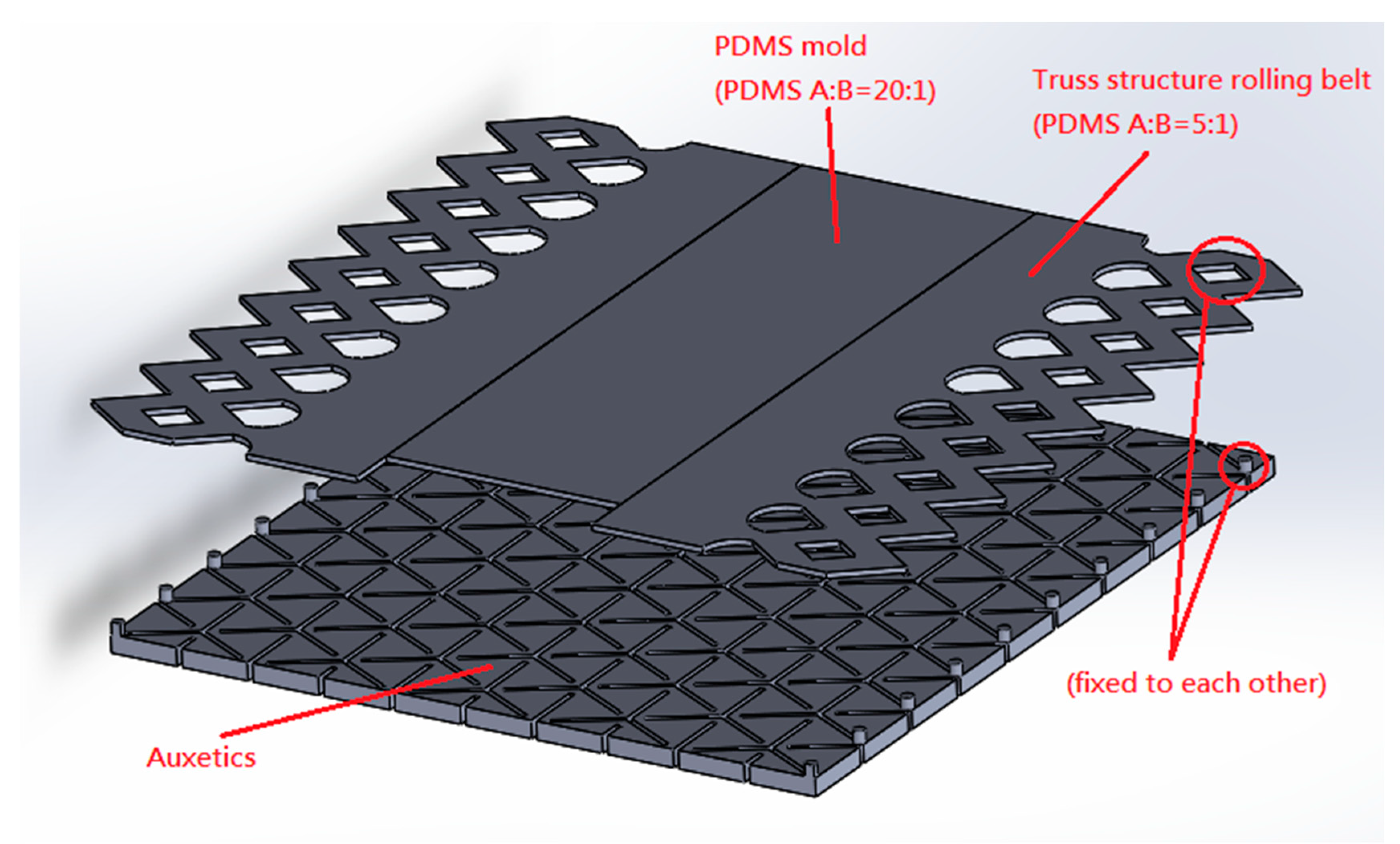
Figure 1. Schematic diagram of the assembly of the auxetics and mold rolling belt.
Processes 11 00931 g001
Figure 2. Installation locations of elastic rings: (A) schematic diagram; (B) side view of the model.
Processes 11 00931 g002
Figure 3. Design parameters of the Y-shaped rigid rotational auxetic structure.
Processes 11 00931 g003
Figure 4. Mechanical property testing of Y-shaped rigid rotational auxetic structure.
Processes 11 00931 g004
Figure 5. Deformation analysis of Y-shaped rigid rotational auxetic structure with different design parameters at the longitudinal strain of 0.05–0.1 and the Poisson’s ratio of 0: (A) change in transverse stress and (B) change in longitudinal stress.
Processes 11 00931 g005
Figure 6. Testing and simulation result with relation to vertical and horizontal tension stress and tension strain: (A) change in horizontal stress and (B) change in vertical stress.
Processes 11 00931 g006
Figure 7. Four design angles set for analyzing the effect of trusswork angle on transverse contraction stress: (A) 73.74°; (B) 106.26°; (C) 122.63°; (D) 132.84°.
Processes 11 00931 g007
Figure 8. Four design angles set for analyzing the effect of trusswork support aspect ratio on transverse contraction stress: (A) 73.74°; (B) 106.26°; (C) 122.63°; (D) 132.84°.
Processes 11 00931 g008
Figure 9. Effect of trusswork angle on transverse contraction stress.
Processes 11 00931 g009
Figure 10. Effect of trusswork support aspect ratio on transverse contraction stress.
Processes 11 00931 g010
Figure 11. (A) Machine roll imprint process; (B) actual machine photo.
Processes 11 00931 g011
Figure 12. Rolling uniformity testing of pressure-sensitive film.
Processes 11 00931 g012
Figure 13. Poisson’s ratio distributions of different truss structure thicknesses and PDMS mold rolling belt thicknesses: (A) PDMS mold rolling belt was designed with a thickness of 0.5 mm and (B) PDMS mold rolling belt was designed with a thickness of 1.5 mm.
Processes 11 00931 g013aProcesses 11 00931 g013b
Table 1. Transverse contraction stress data at various trusswork support widths.
Width (mm)Horizontal Shrinkage Stress (Vertical Tensile Strain = 0.05) (kPa)Horizontal Shrinkage Stress (Vertical Tensile Strain = 0.1) (kPa)Data Trend Line
1.410.64321.286 Y = 212.86 × X
1.511.37222.744 Y = 227.44 × X
1.611.94523.889 Y = 238.9 × X
1.712.65825.316 Y = 253.16 × X
1.813.18526.37 Y = 263.7 × X
1.913.48426.967 Y = 269.67 × X
214.19528.39 Y = 283.9 × X
2.114.64929.298 Y = 292.98 × X
2.215.10630.212 Y = 302.12 × X
2.315.53731.074 Y = 310.74 × X
2.415.75531.51 Y = 315.1 × X
2.516.2132.42 Y = 324.2 × X
2.616.25432.507 Y = 325.07 × X
2.716.72333.446 Y = 334.46 × X
2.817.28834.576 Y = 345.76 × X
2.917.73935.477 Y = 354.77 × X
317.87835.755 Y = 357.55 × X
Table 2. Transverse contraction stress simulation data of the PDMS mold microstructure transfer print area (unit: kPa).
Vertical Tensile Strain0.050.060.070.080.090.1
Poisson’s Ratio
0 12.85915.4318.00220.57423.14525.717
−0.2 18.00221.60325.20328.80332.40436.004
−0.4 23.14627.77532.40437.03341.66246.291
−0.6 28.28933.94739.60545.26350.9256.578
−0.8 33.43340.11946.80653.49260.17966.865
−1 38.57646.29154.00761.72269.43777.152
Table 3. Deformation analysis result of a concave microstructure array mold with a diameter of 100 μm at the longitudinal stress of 0.1 and the Poisson’s ratio of 0.
Thickness1 mm2 mm3 mm
Vertical strain of shape0.2280.230.228
Horizontal strain of shape0.04180.04210.0423
Depth strain of shape−0.10598−0.1062−0.1062
Vertical strain of position spacing0.10040.10060.1008
Horizontal strain of position spacing000
Table 4. Deformation analysis result of a concave microstructure array mold with a diameter of 100 μm at the longitudinal stress of 0.1 and the Poisson’s ratio of −1.
Thickness1 mm2 mm3 mm
Vertical strain of shape0.2720.2760.273
Horizontal strain of shape0.268560.26870.27043
Depth strain of shape−0.174−0.1706−0.1702
Vertical strain of position spacing0.10020.10060.1014
Horizontal strain of position spacing0.0984860.100530.1007
Table 5. Simulation result of different microstructure sizes at the longitudinal stress of 0.05 and the Poisson’s ratio of 0.
Microstructure Diameter100 µm150 µm200 µm250 µm300 µm400 µm
Vertical strain of shape0.1140.110670.1090.10280.09330.07125
Horizontal strain of shape0.0211750.0196450.0201040.0212650.015940.0098
Depth strain of shape−0.053−0.05173−0.0508−0.04456−0.0476−0.04695
Vertical strain of position spacing0.050.05060.05060.05060.05120.0546
Horizontal strain of position spacing000000
Table 6. Simulation result of different microstructure sizes at the longitudinal stress of 0.1 and the Poisson’s ratio of 0.
Microstructure Diameter100 µm150 µm200 µm250 µm300 µm400 µm
Vertical strain of shape0.230.22330.21750.20520.1880.14175
Horizontal strain of shape0.0421820.0413060.035070.0362030.03050.018192
Depth strain of shape−0.1062−0.105867−0.1029−0.1−0.0977−0.09205
Vertical strain of position spacing0.10060.10020.10140.10340.10240.1088
Horizontal strain of position spacing000000
Table 7. Simulation result of different microstructure sizes at the longitudinal stress of 0.05 and the Poisson’s ratio of −1.
Microstructure Diameter100 µm150 µm200 µm250 µm300 µm400 µm
Vertical strain of shape0.1360.1330.1310.1260.11070.0825
Horizontal strain of shape0.1342780.130150.128540.1206920.110160.078815
Depth strain of shape−0.08694−0.08493−0.08262−0.082344−0.07728−0.074935
Vertical strain of position spacing0.050.05080.050.05160.05180.0556
Horizontal strain of position spacing0.04920.05070.05120.05170.05310.0566
Table 8. Simulation result of different microstructure sizes at the longitudinal stress of 0.1 and the Poisson’s ratio of −1.
Microstructure Diameter100 µm150 µm200 µm250 µm300 µm400 µm
Vertical strain of shape0.2720.26730.26150.25240.22170.16475
Horizontal strain of shape0.268560.26030.25710.241380.22030.15763
Depth strain of shape−0.174−0.17−0.1652−0.16472−0.15457−0.14985
Vertical strain of position spacing0.10020.10140.10020.10320.10340.1112
Horizontal strain of position spacing0.09850.101460.102520.10340.10640.1133
Table 9. Effect of truss structure thickness 0.5 mm and PDMS mold rolling belt thickness 0.5 mm of replication molding and replication rate.
Longitudinal Tensile Strain0.050.060.070.080.090.1
MicrostructureDiameter (µm)
Uni-microstructural longitudinal length (µm)200250260255.7270.4264.5276.5
300308.3311.4313.4320.1331.8349.8
400477.5462.8465.4481474.1489.5
Uni-microstructural lateral length (µm)200225.6237.3240.5240.3234.5231.2
300312.6325.6322.5324.4310.8333
400435438.7447437.7421.6422.6
Uni-microstructural height (µm)200232323232424
300394040393939
400353535353435
Longitudinal period distance of microstructure (µm)200511.5516.6528.8529.4532.3547.2
300510.6515.4514523.7538538
400526529.8529.1535.8548563
Lateral period distance of microstructure (µm)200495.5501.5504.5504.8503505.6
300507.6511.7514520.7510.6514.2
400501.5510.7507.8510.7513.6504.6
Replication rate (%)200878990919697
300929697969797
400939496979498
Table 10. Effect of truss structure thickness 1.5 mm and PDMS mold rolling belt thickness 1.5 mm of replication molding and replication rate.
Longitudinal Tensile Strain0.010.020.03
MicrostructureDiameter (µm)
Uni-microstructural longitudinal length (µm)200240.2258.4243.2
400423.4423.2417.1
Uni-microstructural lateral length (µm) 200238.9240.5229.2
400398.8405.4401.5
Uni-microstructural height (µm)200141414
400999
Longitudinal period distance of microstructure (µm)200514.2520517.6
400511.1515.4518.9
Lateral period distance of microstructure (µm)200501498.4496.5
400483.3468.8485.4
Replication rate (%)200959697
400909092
Disclaimer/Publisher’s Note: The statements, opinions and data contained in all publications are solely those of the individual author(s) and contributor(s) and not of MDPI and/or the editor(s). MDPI and/or the editor(s) disclaim responsibility for any injury to people or property resulting from any ideas, methods, instructions or products referred to in the content.