Abstract
AF1410 is a low carbon high alloy ultra-high strength steel. It not only has high strength and high toughness, but also has a high stress corrosion resistance. However, due to the characteristics of hard quality and poor thermal conductivity, AF1410 is a difficult material to process. In the process of milling, the geometric factors of process parameters, the flexible deformation of milling cutter and the flutter of the process system all affect the surface roughness, which makes it difficult to predict the surface roughness of milling parts. In order to solve this problem, a prediction model for surface topography of ultrahigh strength steel AF1410 was studied. To solve this problem, this paper studies the formation of milling surface topography, considers the dynamic displacement of the milling system, proposes a modeling method of surface topography based on the dynamic characteristics of the milling system and forms a prediction model. On this basis, the surface topography of ultra-high strength steel is simulated and analyzed, and the accuracy of the model is verified by experiments. The study realizes the prediction of milling surface topography of AF1410 parts and reveals the formation mechanism of milling surface topography from geometric and physical perspectives.
1. Introduction
Ultra-high strength steel is an alloy steel used to manufacture structural parts with higher stress and is widely used in many fields such as automobiles, ships, aviation aircraft and military equipment [1]. These application scenarios require higher surface quality. Ultra-high strength steel is generally characterized by hard quality and poor thermal conductivity. Therefore, ultra-high strength steel is a kind of material that is difficult to process and its processing quality is difficult to guarantee [2].
According to the degree of alloying and microstructure, ultrahigh strength steel can be divided into low alloy, medium alloy and high alloy ultrahigh strength steel. AF1410 belongs to low carbon high alloy ultrahigh strength steel. AF1410 is a secondary hardening martensitic steel, which has the best toughness among secondary hardening steels. It not only has high strength and high toughness, but also has high stress corrosion resistance.
The machined surface topography of parts is affected by such factors as tool marks during machining, plastic deformation during cutting separation, friction between tool and machined surface, deformation and chatter of machining system, etc. In practical applications, the machined surface topography of parts is mainly described quantitatively by surface roughness [3,4,5]. Surface topography usually defines the functional behavior of the workpiece and affects the wear resistance, corrosion resistance, fatigue strength, lubrication, friction, optical properties and many other aspects of the parts [6]. The surface topography of a part is an important index to ensure its performance. Therefore, it is very important to study the formation mechanism of milling surface topography and achieve accurate surface topography prediction. In recent years, scholars have carried out a lot of studies on the topography of machined surfaces.
Process parameters are the main factors affecting the surface roughness. Kartal, F. [7] analyzed the influence of machining parameters on surface roughness and macroscopic surface characteristics during machining Al-6082 T6 alloy. Durakbasa, M. N. [8] studied the influence of milling parameters on the surface quality of machined parts. Liu, G. [9] studied the high-speed milling of 17-4PH stainless steel and found that notch wear existed in the cutting process. Higher cutting speed would seriously accelerate the formation of notch wear and the roughness value of the machined surface would significantly increase after notch wear. Banerjee, N. [10] took Ti-6Al-4V cutting as an example to study the effect of cooling mode on cutting force and surface roughness. Jersák, J. [11] used the single factor variable comparison method to describe the consistency between cutting efficiency and workpiece surface quality.
In order to optimize milling process parameters and improve surface quality, it is very important to study the formation mechanism of milling surface topography and achieve accurate surface topography prediction. In recent years, researchers have carried out relevant experimental studies and modeling studies on the machined surface topography, and carried out optimization of cutting parameters.
The predicted value of surface roughness in the whole working range can be obtained by using the limited test data, which is helpful to accurately understand the change law of machining surface quality with milling parameters. Alagarsamy, S. V. [12] used the Taguchi method for NC end milling of brass C26130 alloy. The results of variance analysis showed that spindle speed and feed speed are the most influential parameters on surface roughness and tool wear. Li, S. [13] collected noise, vibration, surface texture and roughness during milling, and established a multi-signal monitoring system for nickel metal processing status. A multidimensional feature fusion roughness prediction model with noise, vibration and surface texture as input values and roughness as output values was proposed.
For the milling process, tool parameters and cutting parameters are geometric factors that affect milling surface roughness. Some scholars have proposed surface roughness prediction models based on geometric factors. Arizmendi, M. [14] proposed a milling surface topography simulation method based on finite point mesh discretization. When the cutting edge geometry and cutting edge point trajectory are given, the roughness value can be predicted according to the geometry of the face milling cutter, feed value and step size between holes. Urbikain, G. [15] used the end milling cutter to conduct milling experiments on aluminum alloy Al7075T6 and titanium alloy Ti6Al4V. The geometric model of the surface was established based on the trace left by the simulation tool and the empirical model of surface prediction was established based on the cutting parameters. Wang, L. [16] analyzed the influence of tool runout and workpiece curvature on the height of surface profile. A surface roughness control method based on surface topography analysis for five axis side milling was proposed. The optimized feed rate effectively improved the roughness uniformity and machining quality of the milling surface. Kumar, H. et al. [17,18,19] studied the reflection phenomenon of real surfaces, used the non-contact machine vision method for online measurement of surface roughness and extracted surface texture for surface roughness prediction.
In machining, the surface roughness of the workpiece will be affected by the kinematics of the machining process, the random effects produced by the machine tool, the workpiece and the surrounding environment. Urbikain, G. [20] proposed a geometric model of surface topography in the side milling operation of the circular end milling cutter, and established a time-domain model based on the mechanical and kinematic parameters in the cutting process, such as tool geometry, feed velocity, radial immersion and tool runout. Arizmendi, M. [21] proposed a surface topography prediction model for cylindrical milling considering tool vibration during cutting. The influence of tool vibration was incorporated into the cutting edge trajectory equation, the cutting edge trajectory equation was transformed into an equivalent polynomial equation, and the standard root finder was used to solve the discrete position of the feed direction. Sun, Y. [22] modeled the dynamic crossover behavior of the milling region, determined the dynamic displacement and used these intersection points to construct three-dimensional graphics representing the surface topography of the milling. A method of surface topography prediction in milling was proposed based on dynamic tool vibration. Lu, X. [23] studied the influence of multiple regeneration effects and dynamic response on the surface roughness of Inconel 718 micromilling. In accordance with the actual cutting path and the flexible deformation of micro-milling cutter, the surface topography simulation model was established to predict the surface roughness and the accuracy of the model was verified by experiments. Zhuo, Y. [24] studied the effect of vibration in milling system on surface topography according to the low stiffness and time-varying dynamics of thin-walled parts in milling, and proposed a surface topography prediction model that considered cutting vibration and material removal effects. Chen, Q. H. [25] established the prediction model of surface topography in cylindrical milling based on the workpiece Z-map model and the dynamic cutting force model in cylindrical milling considering the radial runout and axial displacement regeneration effect. The stability lobe diagram was obtained via the zero-order analytical method, and the relationship between spindle speed and surface morphology, tool radial runout and axial displacement after chatter was studied. Chen, W. [26] proposed a modeling method for 3D surface generation in micro-milling based on homogeneous matrix transformation considering the influence of machining nonlinear dynamics. The relationship between the machining process and surface morphology was established considering the kinematics of the machining process, tool runout and nonlinear dynamic regeneration effect of machining system. Li, G. [27] proposed a physical modeling method for tool marks considering the mechanism of face milling. An optimization model based on physical information was established to improve the surface quality of the workpiece with discontinuous surface by optimizing the machining parameters.
According to the above literature, the current research on milling surface roughness mostly adopts experimental and simulation methods. The regression model is established through a large number of experimental data. The simulation method is mainly to explore the machining mechanism, simulate the geometric and physical factors in the cutting process and establish the mathematical model of the position of the tool relative to the workpiece according to the factors that affect the formation of the surface topography. Compared with the experimental method, the simulation method is more cost-effective and can reveal the formation mechanism of surface topography. For the study of the analytical model of roughness, the geometric factors and kinematic parameters in the milling process are considered to establish the simulation model. In the milling process, due to the flexible deformation of the milling cutter and the dynamic displacement of the milling system, the cutting tool deviates from the ideal cutting trajectory, which affects the milling surface topography. The current simulation model of milling surface roughness has not fully considered the flexible deformation of milling cutter and the dynamic displacement of the milling system. In order to better predict the surface topography of the milling system, a surface topography model based on the dynamic characteristics of the milling system was established by combining the flexible deformation model of milling cutter and the dynamic model of the milling system.
The novelty of this paper is that, based on the ideal surface topography modeling method, combined with the flexible deformation model of the milling cutter and the dynamic model of the milling system, the surface topography model based on the dynamic characteristics of the milling system is established for ultra-high strength steel AF1410 milling and the formation mechanism of milling surface topography was revealed.
2. Materials and Methods
2.1. Material Characteristics
AF1410 contains alloy elements such as Co, Ni, Cr and Mo. Diffusion strengthening effect of low carbon martensite and precipitated alloy carbide is adopted. The chemical composition of the material was obtained via spectroscopic analysis. The chemical composition of AF1410 steel used in this study is shown in Table 1 [28]. The material adopts forging blank. The pre-processing heat treatment process of the material is high temperature tempering after normalizing. The hardness of the material is HRC38-39.

Table 1.
Chemical composition (wt.%) of AF1410 steel.
The uniaxial tensile test was used to obtain the basic mechanical parameters of the material. Tensile test equipment is a 100 kN mechanical testing machine (MTS Inc., Eden Prairie, MN, USA). The mechanical properties of AF1410 steel are listed in Table 2 [28]. It is noted that the AF1410 steel has high strength and certain percentage elongation, which makes machining difficult. Therefore, it is necessary to establish the surface topography model of AF1410 steel.
Table 2.
Mechanical properties of AF1410 steel.
2.2. Methods
2.2.1. Surface Roughness Characterization Parameters
When evaluating the surface topography model, qualitative comparison is made between simulated and measured surface topography in shape. At the same time, they are quantitatively evaluated by using the three-dimensional surface amplitude and the two-dimensional roughness parameter profile height arithmetic mean deviation (Ra) of the corresponding section profile [6]. Considering that the dynamic displacement caused by vibration contains certain randomness in the direction and magnitude, the arithmetic mean deviation (Sa) of surface amplitude is used as the index to measure the roughness of the three-dimensional surface. The arithmetic mean deviation of surface amplitude Sa is the arithmetic mean of the height direction distance of the represented surface z(x,y) relative to the datum surface z0(x,y) in the assessment area D. Sa is the average value of the coordinates absolute value of the distribution points of the microscopic components of the surface geometry with respect to the reference plane in the height direction. Sa is an important parameter reflecting the surface roughness in the plane domain. It reflects the surface roughness from the three-dimensional space, which is more comprehensive and objective than the two-dimensional roughness parameter. According to ISO 25178-2-2012, the value of Sa can be calculated by:
where A is the assessment area D, z(x,y) is the height coordinates of the distribution points of the surface microscopic geometric topography, and xii (ii = 1, 2, …, m + 1) and yjj (jj = 1, 2, …, n + 1) are the coordinates of the workpiece grid points in x and y directions, respectively.
2.2.2. Experimental Equipment and Conditions
The machine used in the experiment was HAAS-VF1 vertical machining center (HAAS Inc., Oxnard, CA, USA). The experimental tool was Walther end mill H4020017-10-1 (Walter Inc., Tubingen, Germany). Its material was carbide, its diameter is 10 mm, the overall length is 65 mm, the number of teeth is 4, the elastic modulus is 210 GPa and the experimental clamping suspension length is 40 mm. The milling force sensor was a type 9257B three-way dynamic voltage power sensor (Kistler Inc., Shanghai, China). Shank adopts spring chuck shank. The photography of the milling experiment and force measuring equipment are shown in Figure 1 [28].
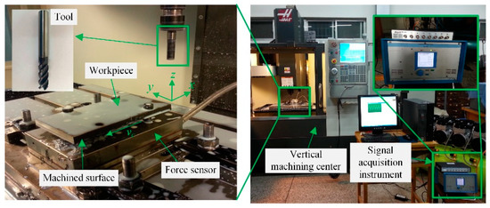
Figure 1.
Milling experiment and force measuring equipment.
The LMS dynamic performance test system was used to obtain system modal parameters. The system is composed of force hammer, acceleration sensor, corresponding data acquisition equipment and signal analysis software LMS Test.Lab8b (LMS Inc., Leuven, Belgium). The experimental equipment is shown in Figure 2. Table 3 shows the tool modal parameters.
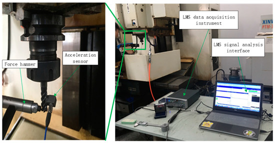
Figure 2.
Experimental equipment and measuring equipment.
Table 3.
Modal parameters of carbide cutting tools.
In order to reduce the influence of high-frequency errors on the results, the surface topography was characterized by three-dimensional surface roughness parameter values and two-dimensional surface roughness parameter values. Noise removal for area (3D) data should be considered when profile (2D) features are applied [29,30]. The non-contact measuring instrument laser confocal microscope DCM-3D (Leica Inc., Weztlar, Germany) was used to measure three-dimensional surface roughness, and the contact measuring instrument RC50H (VALE, Xi’an, Shaanxi, China) was used to measure two-dimensional surface roughness, as shown in Figure 3. Ra is the two-dimensional surface roughness parameter value; Sa is the three-dimensional surface roughness parameter value.
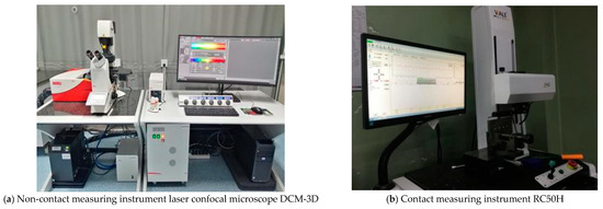
Figure 3.
Surface roughness measuring equipment.
MATLAB was used for data processing and analysis, and a roughness prediction model was established.
3. Results
3.1. Milling Surface Topography Model
3.1.1. Formation of Milling Surface Topography
For the milling process, the diagram of milling surface topography is shown in Figure 4. After determining the cutting parameters and tool geometric parameters, the machined surface topography under ideal machining conditions can be obtained. The boundary point of the machined surface contour was determined by calculating the intersection point of two adjacent tool tooth profiles, and the cutting surface of the workpiece was obtained by connecting two tool points. The profile of the tool relative to the workpiece is determined by the actual cutting path of the tool in the process of machining. The actual cutting path of the tool is not only related to the cutting parameters, but also to the dynamic characteristics of the process system during machining [31]. As shown in Figure 5, the chatter of the process system leads to the relative vibration displacement of tool and workpiece and the dynamic parameters of the milling system change with the change in machining position and cutting depth. The formation process of surface topography is affected by the dynamic characteristics of the milling system, so that the ideal tool path is disturbed. Due to the relative vibration between the tool and the workpiece, the subsequent teeth will cut the higher residual surface out of the cutting front teeth. Therefore, in the milling process, it is necessary to consider the influence of the dynamic characteristics of the tool-workpiece system in the machining process and establish the milling surface topography model from the physical angle.
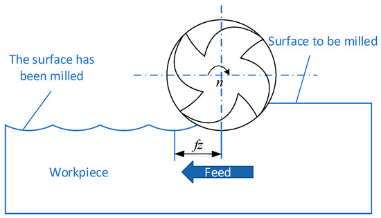
Figure 4.
Milling machining ideal surface.
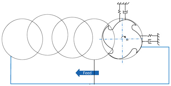
Figure 5.
Surface topography considering dynamic characteristics of the milling system.
3.1.2. Milling Tool Flexible Deformation Model
Figure 6 shows the peripheral milling process, where x is the feed direction, y is the feed normal direction and Z is the axial direction. The coordinate system is fixed on the workpiece and the origin of the coordinate is the center point of the front end of the milling tool in the initial state.
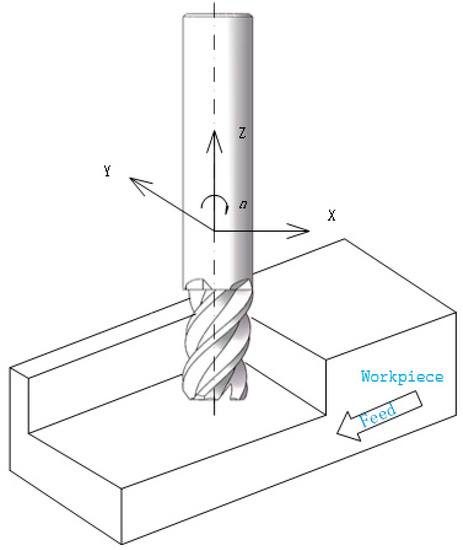
Figure 6.
Milling process.
The milling surface is machined from the circumferential surface of the end milling tool. The machined surface of the workpiece is perpendicular to the feed direction. Any deviation in the y axis direction will produce static deviation. Because the diameter of the tool is relatively small compared to the length from collet to tool head, the tool is usually the weakest link in a machine tool system. The end mill can be simplified as a cantilever structure by means of a chuck and chuck cantilever on a spindle. Figure 7 shows the flexible deformation model of the end milling tool.
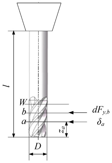
Figure 7.
Flexible deformation model of the end milling tool.
The milling force produced by the spiral end mills changes with the rotation of the end mills. In order to explain the formation mechanism of the milling surfaces, the case of straight slot end mills (that is, the spiral angle is 0) is considered first, and the deviation perpendicular to the workpiece surface direction (normal y direction) is the most significant. Static deviation of the free end of the end milling tool caused by the normal force (Fy) is:
where E is the elastic modulus of the milling tool material, I () is the moment of inertia of the milling tool shaft, and l is the distance of the tool from the chuck to the end face.
The value of the milling force by it is proportional to the chip thickness can be calculated by [32]:
where φ is the angle between the tool tooth and the y axis, h(φ) is chip thickness (h(φ) = fzsinφ), Kt and Kr are milling force coefficient and fz is feed per tooth (the unit is mm/z). The tool tooth generates the workpiece surface when it is in contact with the workpiece or located on the y axis, as shown in Figure 8. The schematic diagram of the milling area is shown in Figure 9. When the tool teeth are on the y axis, the chip thickness is 0. This happens in up milling (φ = 0) and in down milling (φ = π). Therefore, if the elasticity and cutting amount of the tool are not considered, the static deviation will be 0 when only one tool tooth is cutting for straight slot end mills. This is why the radial contact angle common in finishing is much smaller than the intertooth angle of the tool. However, if two or more tool teeth are involved in the cutting at the same time, the cutting force is not zero when one of the tool teeth is on the y axis. This is because the other spiral grooves are cutting in the cutting contact area. In this case, for reverse milling, the deviation is in the direction of entering the workpiece surface, thus causing overcut shape error; for down milling, the deviation is in the direction of leaving the surface, causing undercut shape error.
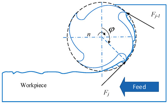
Figure 8.
Tool teeth generate workpiece surface when in contact with workpiece.
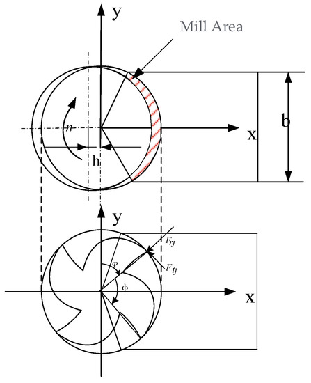
Figure 9.
Diagram of Mill Area.
When using the spiral groove end milling tool, the spiral groove cutting edge is located at the y axis at the bottom of the end milling cutter and the contact angle of the cutter position φ(z = 0) = 0. With the rotation of the tool, the top of the spiral groove moves to the position of the tool contact angle. At this time, the position of the coordinate z from the top of the spiral groove is just in the position of the y axis, forming the workpiece surface. Because the normal cutting force Fy is not 0 at this time, the elastic displacement of the end milling tool will produce deviation on the workpiece surface. Because of the helical angle, the cutting edge points forming the workpiece surface will move up along the helical groove. Depending on the number of spiral slots and the cutting width, there may be more than one cutting edge point in contact with the formed surface or located on the y axis. The schematic diagram of the Mill Area is shown in Figure 9. The axial position of the contact point is:
where β is the spiral angle of end milling tool, j is the blade number, ϕ is the intertooth angle which can be calculated by ϕ = 2π/Z.
As shown in Figure 7, the ap of the axial cutting depth of the tool is divided into W micro-elements, which rotate with the increment of the tool angle δ. The cutting depth of each element is ΔZ = ap/W, and the cutting force element generated by element M is:
The contact angle of element b is φ(b):
The y-direction deviation of the cutting force on element b at the contact point za can be given by the cantilever beam formula:
The total static deviation generated at axial contact points can be obtained by superimposing the deviation generated by all W micro cutting forces acting on the end mill:
Generally, the effect of static forces is ignored in the stability analysis of the milling systems [33,34]. However, according to the above analysis and calculation, the flexible deformation caused by the static force of the end mill will produce geometric deviations in the milling area, which will affect the surface topography. In order to establish a more accurate prediction model of surface topography, in this paper, it is proposed that the geometric deviation of surface is calculated using the milling force based on chip thickness and the geometric deviation is taken as one of the components of surface roughness parameters.
3.1.3. Tool-Workpiece Dynamic Displacement Based on Regenerative Flutter Model
The dynamic model of milling ultra-high strength steel with a carbide tool is the theoretical basis for analyzing the dynamic displacement of tool and workpiece. According to the characteristics of rigid and flexible combination between tool and workpiece, the hard alloy tool milling ultra-high strength steel is assumed to be a flexible tool–rigidity workpiece dynamic milling system. The dynamic milling process dynamic model is shown in Figure 10. The system is simplified as a flexible double degree of freedom system perpendicular to the x and y directions.
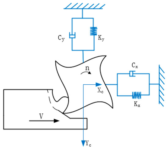
Figure 10.
Dynamic model of two degrees of freedom dynamic milling process.
Considering the regenerative chip thickness caused by the dynamic displacement of the tool induced by vibration, the dynamic equation is a delay differential equation set with excitation [32].
where, M is the tool modal mass matrix and its unit is kg, C is the tool modal damping matrix and its unit is N S·m−1, K is the tool modal stiffness matrix and the unit is N·m−1, q(t) is the modal coordinates of the tool’s dynamic displacement at time t and its unit is mm, q(t) = [x(t) y(t)] T, Ks(t) is the cutting force calculation coefficient matrix of the tool at time T, T is cutting period of tool teeth, namely time delay and its unit is S, F0(t) is the static cutting force matrix of the tool at time T and its unit is N.
The calculated coefficient matrix Ks(t) of the cutting force is
where gj(t) is the transformation function; if the cutter tooth j participates in milling, then gj(t) = 1; otherwise, gj(t) = 0. The parameters Kt and Kr are tangential and radial milling force coefficients, respectively, and φ are the position angle of the milling tool.
Static cutting force matrix F0(t)
Ks(t) and F0(t) are periodic matrices, Ks(t) = Ks(t + T), F0(t) = F0(t + T).
In Formula (10), , ; namely, ; q(t) is the dynamic displacement of the tool. Then, Formula (10) can be expressed as
where A0 is the constant matrix of systematic time-invariant property, A(t) and B(t) are the comprehensive coefficient matrices of dynamic cutting force considering regeneration effect and A(t) and B(t) are periodic matrices, namely, ,
Take the integral at the time period T, k = 0, 1, 2, …, m, at the time interval [kτ, kτ + τ], x = x(kτ), the solution of Equation (15) is
x(kτ + τ) = xk + 1, then
A(kτ + τ − ξ) and B(kτ + τ − ξ) are periodic coefficient matrix, x(kτ + τ − ξ) is status item, x(kτ + τ − ξ − T) is the time delay item. They are approximated by linear interpolation in the time interval [kτ, kτ + τ].
Here, ,
Here, ,
Here, m = T/τ.
The static term is , approached by pressing down on time interval [kτ, kτ + τ].
Here, ,
Substitute Formulas (17)–(21) into Formula (16); xk+1 is expressed as:
Here, Pk is expressed as
If [I − Rk +1] is nonsingular and the inverse matrix [I − Rk +1]−1 exists, then
Count all time units; set ; construct discrete mapping
In the Formula (24), Qk and Ek are expressed in the following formula
The dynamic displacement of the tool–workpiece in the milling system of ultra-high strength steel is solved in the calculation.
3.1.4. Milling Surface Topography Model
It can be seen from the motion of the milling tool that the tool has translation and harmonic motion along the x and y axes. The trajectory equation of the j cutting edge tip milling process is obtained as follows:
where F is the feed speed and its unit is mm/s, fz is the feed per tooth and its unit is mm/z, R is the milling tool radius and its unit is mm, n is the spindle speed and its unit is r/min, t is the time and its unit is s, Z is the number of cutting edges of a milling tool.
The trajectory equation of the end milling tool j cutting edge with spiral Angle β at height Z is considered as follows:
After determining the cutting parameters and tool geometry parameters, the machined surface topography under ideal machining conditions can be obtained. In the process of milling, the flexible deformation of the milling tool and the dynamic displacement of the milling system lead to the tool deviating from the ideal cutting trajectory, which affects the cutting surface topography. In order to predict the milling surface topography better, a surface topography model based on the dynamic characteristics of the milling system was established on the basis of the modeling method of ideal surface topography, combined with the established milling tool flexible deformation model and the milling system dynamics model.
where x, y is the dynamic displacement of the milling tool, β is the milling tool helix angle, z is the milling tool micro element height, and δx and δy are the deviations caused by flexible deformation of the milling tool.
3.2. Simulation of Surface Topography Based on Dynamic Characteristics of Milling System
3.2.1. Simulation Model
Ultra-High Strength Steel Workpiece Model
It is impossible to predict the surface topography in the milling process accurately by calculating the tool path between the intersecting points of the geometric profiles of adjacent tool teeth. In order to obtain the surface topography of the ultra-high strength steel milling workpiece, the workpiece was meshed along the feed direction and the axial direction. Then, with Δx and Δz as intervals, the whole workpiece is divided into m × n cubes with equal lengths along the feed direction and the axial direction. The formation process of milling surface topography is regarded as a process in which the geometric profile of the milling tool duplicates the height of several small discrete cubes.
The matrix H = [hi,j] (i = 1, 2, …, m; j = 1, 2, …, n) is used to represent the residual height of the workpiece milling face to the corresponding position. By searching each grid in turn, the residual height value was obtained and the milling surface topography was reconstructed. The appropriate mesh density should ensure that the simulation data is not distorted and the program has reasonable computing amount. If the mesh density is too high, the tool elements are too dense, resulting in a sharp increase in computing amount of the program or even failure. If the mesh density is too small and each cell is too large, the surface topography simulation data is distorted and cannot reflect the real surface topography.
Milling Tool Micro Element Setting
The milling tool is divided into micro units and the projection height of each axial micro unit is obtained in the ultra-high strength steel workpiece. The length of the tool discrete element depends on the density generated by the workpiece mesh. Ensure that after the workpiece mesh is generated, each unit has the repetition of the tool geometric outline, that is, the micro-units divided into tool teeth can traverse all the workpiece mesh. The projected length of axial microcells on the meshed surface should be less than the meshes of the least spaced workpiece. In the milling process, the surface topography of the milling side wall is affected by the part of the milling tool involved in cutting. Therefore, only the cutting edges involved in cutting need to be discretized in microunits.
3.2.2. Simulation Program Flow
The milling surface topography model was established by combining the milling system dynamic model and tool contour geometry model. Figure 11 shows the flowchart. The input variables are milling parameters and tool geometry parameters. According to the ideal cutting path of the tool, the instantaneous cutting thickness and instantaneous cutting force are calculated. According to the dynamic response model of the milling system, the dynamic displacement of the cutting tool under the current cutting force was obtained, which was added to the ideal cutting path of the tool to obtain the actual cutting path of the tool. Through the principle of tool shape replication, the tool contour is mapped to the workpiece surface. The surface roughness was obtained by extracting the workpiece surface and reconstructing the surface topography of the milling side wall.
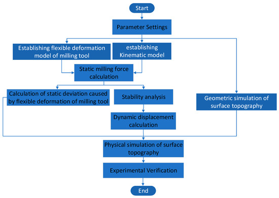
Figure 11.
Physical simulation flow of milling surface topography of ultra-high strength steel.
The physical simulation process of milling surface topography based on the dynamic characteristics of the milling system is shown in Figure 11. The specific simulation process is as follows:
Parameter Setting
- Cutting parameter setting
Main spindle speed N, feed per tooth fz, axial milling depth ap, radial milling depth ae, etc.
- 2.
- Tool parameter setting
Set the milling tool radius R, the total number of tool teeth Z, helix Angle β, etc., and set the axial position angle increment λθ of the adjacent two discrete points on the tool tooth.
- 3.
- Time step setting
In order to obtain the actual cutting trajectory of milling tool teeth on the ultra-high strength steel workpiece, it is necessary to decompose the machining time into multiple steps and calculate the cutting trajectory of each micro-element at the time step of each element in addition to discretizing the axial micro-element of tool teeth. In the process of milling, the tool moves along the sweep path curve of the discrete points of the tool tooth, which is a cycloid. When setting the time step, ensure that the cycloid arc length per unit time step is less than the mesh length of the workpiece, i.e.,
In the formula, Δs is the arc length of cycloid movement within a unit step, Δx is the mesh length generated by the workpiece along the feed direction and Δy is the mesh length generated by the workpiece along the feed normal direction. According to the cycloid formula, the arc length per unit time is calculated as follows
Substitute Equation (31) into Equation (33), we obtain
By integrating the arc length of unit time, the arc length of cycloid movement in unit step time is obtained
where Δt is the unit step time. When the mesh size of the workpiece is determined, the maximum unit step time is determined.
Stability Analysis
According to the established dynamic model of the ultra-high strength steel milling system and the stability determination method of the full discrete method, the stability is determined by the eigenvalue of the state transition matrix. At the same time, the stability can also be determined via the spectrum analysis of the dynamic displacement of the tool and the workpiece.
Static Milling Force Calculation
The static milling force of ultra-high strength steel milling is calculated based on the semi-analytical method.
Tool and Workpiece Dynamic Displacement Calculation
According to the theory, the dynamic displacements of tool and workpiece under the combined action of static force and dynamic force caused by regenerative effect are solved.
Geometric Simulation of Surface Topography
(1) Determine the position of the tool teeth.
After the time step is set, the tool rotates at a certain angle in each unit step. The angle of the tool tooth position is defined as the angle change between the tool head and the y axis of the workpiece coordinate system. When the spindle rotates a full circle, the angle of the tool tooth position changes from 0 to 2π. The angular velocity of the tool is zero. Instantaneous tooth angle of tool tooth is:
where n as the spindle speed, with units of r/min, and dt is the unit time step.
When the time step and spindle speed are set, the spindle rotates once to calculate the number of changes in the position angle of the tool tooth. Each rotation of a milling tool is considered as a microunit. The unit time step of the instantaneous tooth position angle is dϕ(t), and the number of micro elements is i when the spindle rotates once.
(2) Determine the participating milling tool teeth
A milling tool has two or four cutting edges and the cutting force consists of the cutting force on each cutting edge during the cutting process. There is an angle between the milling tool teeth. The instantaneous angle of different teeth is different in the milling process. The included angle at the tip of the Z cutting edge is
The tool teeth are numbered sequentially when they are first involved in cutting. The first tooth involved in cutting is the first tooth. At time t, the tooth position angle of the j-tooth is as shown in Formula (38).
(3) Axial dispersion of tool teeth
Milling tool teeth have spiral angles, so instantaneous tooth angle and instantaneous cutting thickness change simultaneously at different heights. In order to simulate the actual milling process, the milling tool was discretized in the axial direction and the instantaneous tooth angle and instantaneous cutting thickness of each axial micro element were calculated. The instantaneous cutting force of each axial micro-element is calculated by using the instantaneous cutting thickness. The instantaneous cutting force of the milling tool is the component of the instantaneous cutting force of each axial micro-element.
Physical Simulation of Surface Topography
Through geometric simulation, the tool tooth sweep information of each mesh point of the workpiece driven by geometric motion is obtained. However, under the influence of vibration-induced dynamic displacement of the tool and the workpiece, the tool tooth sweep information obtained from geometric simulation will change, resulting in the change of the sweep height of the mesh point of the workpiece. Therefore, it needs to be recalculated in the physical simulation of surface topography considering the dynamic displacement. Because the vibration-induced dynamic displacements of tool and workpiece are relatively small in actual machining, the actual height of the machined surface under vibration can be calculated based on the Taylor formula based on the geometric simulation results of surface topography and dynamic displacements of tool and workpiece and then the physical simulation results of surface topography can be obtained.
3.3. Experimental Verification
In order to verify the validity of the simulation results of the surface topography based on the dynamic characteristics of the milling system, milling experiments were carried out using the tool conditions of the stability experiment to obtain the actual machined surface. Then the surface topography was measured and the measurement results were compared with the simulation results to verify the validity of the simulation results.
The measured and simulation results of the milling surface topography of ultra-high strength steel are shown in Figure 12. The change trend of measured and simulated surface topography is consistent, the shape is close and the simulated and measured surface roughness parameters are close, the simulated values of Sa have an average error of 10.9%. The results show that the milling system simulation results based on the dynamic characteristics of ultra-high strength steel can get close to the measured surface topography. The difference between the geometric simulation and the measured surface section profile Ra is 0.16 μm and the difference between the simulation considering dynamic characteristics and the measured surface section profile Ra is 0.07 μm, indicating that the simulation considering dynamic characteristics is closer to the measured value than the geometric simulation. Because the material in the axial plastic flows to a certain extent and due to the large milling depth, the milling force is bigger, making the plastic deformation of metal in the cutting area larger. At the same time, under the strong impact of forced vibration, the tool significantly deviates from the spindle center axis, which may lead to a secondary back angle cutting. At this point, the tool increases friction, impact force and friction force after the tooth surface touches the workpiece. Under the joint action of the metal near the blade, a large plastic flow can be generated. When the flow direction is along the feed direction, the metal near the plastic flow between layers will undergo plastic deformation and elastic deformation. Therefore, when the blade cuts away from the workpiece, the elastic deformation is restored, so that the measured profile fluctuation is different from the theoretical simulation. However, the geometric simulation does not calculate the flexible deformation of the milling cutter and the dynamic deviation in the milling process, so the simulation error is large. In addition, the error of modal parameters measured via the force hammer percussion method will have a direct impact on surface topography prediction.
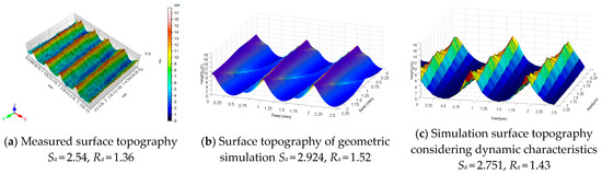
Figure 12.
Measurement and simulation results of milling surface topography of ultra-high strength steel.
In addition, the error of modal parameters measured by force hammer will also have a direct impact on surface topography prediction.
On the whole, the simulation results are in good agreement with the measured ones, which can be used to predict the actual machined surface topography.
4. Discussion
In order to further analyze the influence of different milling parameters on the surface topography, the surface topography under different conditions was measured and predicted. The two-dimensional surface roughness parameter value Ra and the three-dimensional surface roughness parameter value Sa were extracted from the measurement results and simulation results, respectively. The simulation results and the measured results are shown in Figure 13. It can be seen that the simulation results are in good agreement with the measured results in terms of the influence trend of milling parameters on surface roughness.
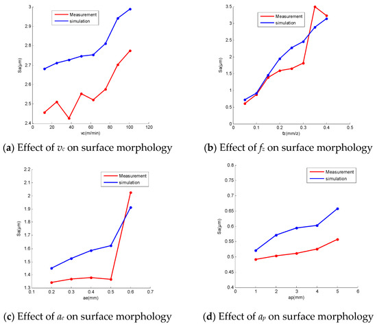
Figure 13.
Effect of milling parameters on surface topography.
The comparison of surface topography at different milling speeds is shown in Figure 14. In terms of amplitude and trend, the simulation results are in good agreement with the experimental values. The simulated values of Ra have an average error of 9.98%. The milling speed has no obvious effect on the surface topography only considering the influence of geometric factors. However, milling speed is the main factor affecting milling stability. It can be seen from Figure 13a and Figure 14 that when the milling speed is small, the dynamic displacement of the milling system is small. When the milling speed vc is higher than 87.92 m/min, the dynamic displacement of the milling system increases sharply and the Sa deviation value of the milling surface becomes larger and larger.
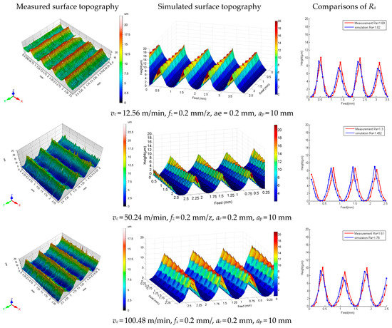
Figure 14.
Surface topography at different milling speeds.
fz is the most significant process parameter that affects surface roughness through geometric factors. Figure 13b and Figure 15 show that the simulation results have the same periodicity and variation trend as the experimental values. The simulated values of Ra have an average error of 10.93%. The Sa of the machined surface increases with the increase of fz, which is caused by the fact that the height of the residual body on the machined surface increases with the increase in fz. However, when fz is small, the dynamic displacement of the milling system is small. With the increase in fz, the Sa deviation value of the milling surface becomes larger and larger, and the amplitude of the dynamic displacement of the tool and the workpiece increases with the increase in fz. The dynamic displacement leads to a change in the actual feed route and the feed amount in the machining process, and then an increase in the residual volume of the surface, resulting in a change in the surface roughness.
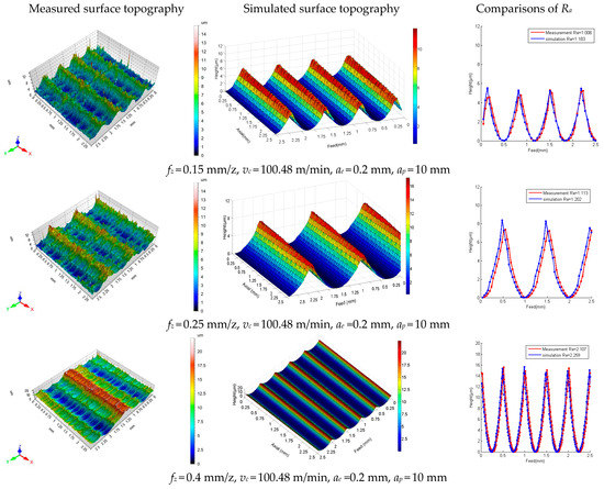
Figure 15.
Surface topography with different feed rate of each tooth.
From the geometric point of view, the increase in radial cutting depth ae will increase the height of the residual body on the machined surface in the intermittent feeding direction, so the surface roughness characterization parameters Sa will increase with the increase in ae. At the same time, radial cutting depth ae affects the dynamic displacement of the tool and workpiece by affecting the physical factors such as cutting force and cutting stability, and finally indirectly affects the surface topography of parts. It can be seen from Figure 13c and Figure 16 that when the radial cutting depth ae is greater than 0.5 mm, the dynamic displacement of the milling system increases sharply and the Sa deviation value of the milling surface becomes larger and larger. The simulated values of Ra have an average error of 7.44%.
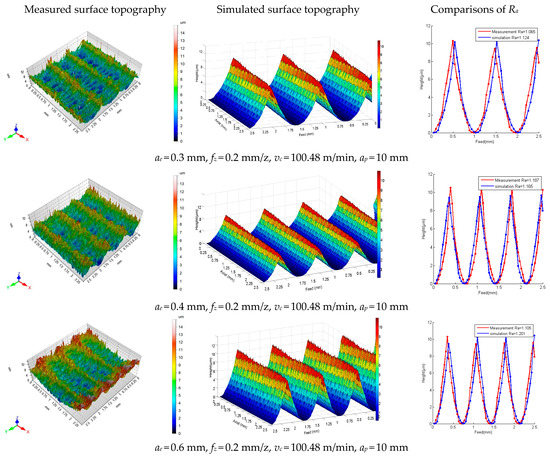
Figure 16.
Surface topography of different radial milling depths.
Axial milling depth directly determines the stability and dynamic displacement of the milling system and then has a direct impact on the surface topography. It can be seen from Figure 13d and Figure 17 that ap directly affects the dynamic displacement of the cutting tool in an ultra-high strength steel milling, thus causing the change in the roughness of the machining surface. However, when ap = 5 mm, the system is in an unstable state. Most of the self-excited vibration energy caused by the cutter teeth in the range of cutting the workpiece cannot rely on free vibration consumption after cutting the workpiece to the next cutter teeth before cutting the workpiece, which causes the dynamic displacement of the tool to diverge, resulting in a large range of vibration, so that the roughness of the machining surface increases sharply. The simulated values of Ra have an average error of 11.32%.
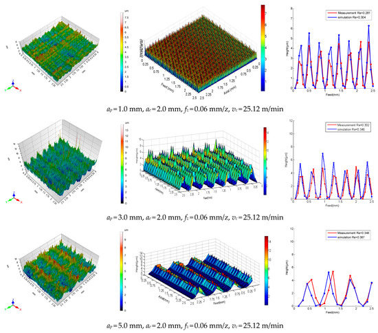
Figure 17.
Surface topography of different axial radial milling depths.
5. Conclusions
In this paper, a surface topography modeling method based on the dynamic characteristics of the milling system is proposed considering the dynamic displacement of the milling system. On this basis, the surface topography of ultra-high strength steel was simulated and analyzed and the formation mechanism of surface topography was revealed from geometric and physical perspectives. According to the verification experiment, the simulation value is in good agreement with the measured value, indicating that the prediction model can be used to predict the surface topography of an ultra-high strength steel milling in actual production instead of in an experiment.
The roughness prediction model considers both the flexible deformation of the milling cutter and the dynamic displacement of the milling system. The average error of the simulated value of Sa is 10.9%, which can accurately describe the surface morphology under the combination of the static deformation of the cutter and the regenerative vibration of the milling system. The difference between the geometric simulation and the measured surface profile Ra is 0.16 μm. The difference between the dynamic characteristic simulation and the measured surface profile Ra is 0.07 μm. These show that the simulation considering dynamic characteristics is closer to the measured value than the geometric simulation.
Based on the surface topography analysis of the dynamic characteristics of the milling system, the influence of different milling parameters on the surface topography is obtained. If only geometric factors are considered, the influence of vc, ae and ap on the surface morphology is not obvious. However, when the milling speed vc is higher than 87.92 m/min, the radial cutting depth ae is greater than 0.5 mm and ap is greater than 5 mm, the dynamic displacement of the milling system increases sharply, the system is in an unstable state and the roughness of the machined surface increases sharply.
Author Contributions
Conceptualization, F.Y. and X.W.; methodology, J.X.; validation, J.X. and Q.Z.; formal analysis, Y.L.; investigation, J.X.; resources, F.Y.; data curation, X.W.; writing—original draft preparation, J.X.; writing—review and editing, J.X.; visualization, X.W.; supervision, Y.L.; project administration, Q.Z. All authors have read and agreed to the published version of the manuscript.
Funding
This work was funded by Innovation and Intelligence Base of New Energy Automobile Science and key Technology 111 Project (Grant No. B17034). State Administration of Foreign Experts Affairs, Ministry of Education.
Data Availability Statement
The data used to support the findings of this study are available from the corresponding author upon request.
Conflicts of Interest
The authors declare no conflict of interest.
References
- Araki, T. Ultrahigh-strength Steels. J. Tetsu-Hagane 2010, 52, 163–186. [Google Scholar] [CrossRef] [PubMed]
- Kernen, L.; Kangaspuoskari, M.; Niskanen, J. Ultrahigh-strength steels at elevated temperatures. J. Constr. Steel Res. 2021, 183, 106739. [Google Scholar] [CrossRef]
- Zhu, L.; Liu, C. Recent progress of chatter prediction, detection and suppression in milling. Mech. Syst. Signal Process. 2020, 143, 106840. [Google Scholar] [CrossRef]
- Artetxe, E.; Olvera, D.; de Lacalle, L.N.L.; Campa, F.J.; Olvera, D.; Lamikiz, A. Solid subtraction model for the surface topography prediction in flank milling of thin-walled integral blade rotors (IBRs). Int. J. Adv. Manuf. Technol. 2017, 90, 741–752. [Google Scholar] [CrossRef]
- Sun, Y.; Jia, J.; Xu, J.; Chen, M.; Niu, J. Path, feedrate and trajectory planning for free-from surface machining: A state-of-the-art review. Chin. J. Aeronaut. 2022, 35, 12–29. [Google Scholar] [CrossRef]
- Du, S.; Xi, L. High Definition Metrology Based Surface Quality Control and Applications; Springer: Berlin/Heidelberg, Germany, 2019. [Google Scholar]
- Kartal, F.; Yerlikaya, Z.; Gkkaya, H. Effects of machining parameters on surface roughness and macro surface characteristics when the machining of Al-6082 T6 alloy using AWJT. Measurement 2017, 95, 216–222. [Google Scholar] [CrossRef]
- Durakbasa, M.N.; Akdogan, A.; Vanli, A.S.; Bulutsuz, A.G. Optimization of end milling parameters and determination of the effects of edge profile for high surface quality of AISI H13 steel by using precise and fast measurements. Measurement 2015, 68, 92–99. [Google Scholar] [CrossRef]
- Liu, G.; Zou, B.; Huang, C.; Wang, X.; Liu, Z. Tool damage and its effect on the machined surface roughness in high-speed face milling the 17-4PH stainless steel. Int. J. Adv. Manuf. Technol. 2016, 83, 257–264. [Google Scholar] [CrossRef]
- Banerjee, N.; Sharma, A. Multi-Point Injection Minimum Quantity Lubrication Machining. Mater. Sci. Forum. 2015, 830–831, 108–111. [Google Scholar] [CrossRef]
- Jersák, J.; Simon, S. Influence of Cooling Lubricants on the Surface Roughness and Energy Efficiency of the Cutting Machine Tools. Int. J. Appl. Mech. 2017, 22, 779–787. [Google Scholar] [CrossRef]
- Alagarsamy, S.V.; Ravichandran, M.; Meignanamoorthy, M.; Sakthivelu, S.; Dineshkumar, S. Prediction of surface roughness and tool wear in milling process on brass (C26130) alloy by Taguchi technique. Mater. Today Proc. 2020, 21, 189–193. [Google Scholar] [CrossRef]
- Li, S.; Li, S.; Liu, Z.; Vladimirovich, P.A. Roughness prediction model of milling noise-vibration-surface texture multi-dimensional feature fusion for N6 nickel metal. J. Manuf. Process. 2022, 79, 166–176. [Google Scholar] [CrossRef]
- Arizmendi, M.; Jiménez, A. Modelling and analysis of surface topography generated in face milling operations. Int. J. Mech. Sci. 2019, 163, 105061. [Google Scholar] [CrossRef]
- Urbikain, G.; Trejo, D.O.; Luo, M.; Lacalle, L.; Elías-Zuiga, A. Surface roughness prediction with new barrel-shape mills considering runout: Modelling and validation. Measurement 2021, 173, 108670. [Google Scholar] [CrossRef]
- Wang, L.; Ge, S.; Si, H.; Yuan, X.; Duan, F. Roughness control method for five-axis flank milling based on the analysis of surface topography. Int. J. Mech. Sci. 2020, 169, 105337. [Google Scholar] [CrossRef]
- Kumar, H.; Ramkumar, J.; Venkatesh, K.S. Surface texture evaluation using 3D reconstruction from images by parametric anisotropic BRDF. Measurement 2018, 125, 612–633. [Google Scholar] [CrossRef]
- Too, M.X.; Ratnam, M.M.; Akil, H.M. Investigation on the effect of machining parameters on surface roughness during turning of kenaf fiber-reinforced composite using non-contact vision method. Int. J. Adv. Manuf. Technol. 2020, 110, 309–325. [Google Scholar] [CrossRef]
- Nouhi, S.; Pour, M. Prediction of surface roughness of various machining processes by a hybrid algorithm including time series analysis, wavelet transform and Multi View Embedding. Measurement 2021, 184, 109904. [Google Scholar] [CrossRef]
- Urbikain, G.; Lacalle, L.D. Modelling of surface roughness in inclined milling operations with circle-segment end mills. Simul. Model. Pract. Theory 2018, 84, 161–176. [Google Scholar] [CrossRef]
- Arizmendi, M.; Campa, F.J.; Fernández, J.; Lacalle, L.; Gil, A.; Bilbao, E. Model for surface topography prediction in peripheral milling considering tool vibration. CIRP Ann.-Manuf. Technol. 2009, 58, 93–96. [Google Scholar] [CrossRef]
- Sun, Y.; Shi, Z.; Guo, Q.; Xu, J. A novel method to predict surface topography in robotic milling of directional plexiglas considering cutter dynamical displacement. J. Mater. Process. Technol. 2022, 304, 117545. [Google Scholar] [CrossRef]
- Lu, X.; Hu, X.; Jia, Z.; Liu, M.; Liang, S.Y. Model for the prediction of 3D surface topography and surface roughness in micro-milling Inconel 718. Int. J. Adv. Manuf. Technol. 2018, 94, 1–14. [Google Scholar] [CrossRef]
- Zhuo, Y.; Han, Z.; An, D.; Jin, H. Surface topography prediction in peripheral milling of thin-walled parts considering cutting vibration and material removal effect. Int. J. Mech. Sci. 2021, 211, 106797. [Google Scholar] [CrossRef]
- Chen, Q.H. Modelling and simulation of surface topography machined by peripheral milling considering tool radial runout and axial drift. Proc. Inst. Mech. Eng. Part B J. Eng. Manuf. 2019, 233, 2227–2240. [Google Scholar] [CrossRef]
- Chen, W.; Xie, W.; Huo, D.; Kai, Y. A novel 3D surface generation model for micro milling based on homogeneous matrix transformation and dynamic regenerative effect. Int. J. Mech. Sci. 2018, 144, 146–157. [Google Scholar] [CrossRef]
- Li, G.; Du, S.; Wang, B.; Lv, J.; Deng, Y. High Definition Metrology-Based Quality Improvement of Surface Texture in Face Milling of Workpieces with Discontinuous Surfaces. J. Manuf. Sci. 2022, 144, 031001. [Google Scholar] [CrossRef]
- Xu, J.; Yan, F.; Li, Y.; Yang, Z.; Li, L. Multiobjective optimization of milling parameters for ultrahigh-strength steel af1410 based on the nsga-ii method. Adv. Mater. Sci. Eng. 2020, 2020, 8796738. [Google Scholar] [CrossRef]
- Podulka, P. Selection of Methods of Surface Texture Characterisation for Reduction of the Frequency-Based Errors in the Measurement and Data Analysis Processes. Sensors 2022, 22, 791. [Google Scholar] [CrossRef]
- Giusca, C.L.; Claverley, J.D.; Sun, W.; Leach, R.K.; Helmli, F.; Chavigner, M. Practical estimation of measurement noise and flatness deviation on focus variation microscopes. CIRP. Ann.-Manuf. Technol. 2014, 63, 545–548. [Google Scholar] [CrossRef]
- Zhao, C.; Lv, J.; Du, S. Geometrical deviation modeling and monitoring of 3D surface based on multi-output Gaussian process. Measurement 2022, 199, 111569. [Google Scholar] [CrossRef]
- Altintas, Y. Manufacturing Automation: Metal Cutting Mechanics, Machine Tool Vibrations, and CNC Design, 2nd ed.; Cambridge University Press: Cambridge, UK, 2012. [Google Scholar]
- Ding, Y.; Zhu, L.; Zhang, X.; Ding, H. Response Sensitivity Analysis of the Dynamic Milling Process Based on the Numerical Integration Method. Chin. J. Mech. Eng. 2012, 25, 940–946. [Google Scholar] [CrossRef]
- Yu, L. Prediction of chatter considering the effect of axial cutting depth on cutting force coefficients in end milling. Int. J. Adv. Manuf. Technol. 2018, 96, 3345–3354. [Google Scholar] [CrossRef]
Disclaimer/Publisher’s Note: The statements, opinions and data contained in all publications are solely those of the individual author(s) and contributor(s) and not of MDPI and/or the editor(s). MDPI and/or the editor(s) disclaim responsibility for any injury to people or property resulting from any ideas, methods, instructions or products referred to in the content. |
© 2023 by the authors. Licensee MDPI, Basel, Switzerland. This article is an open access article distributed under the terms and conditions of the Creative Commons Attribution (CC BY) license (https://creativecommons.org/licenses/by/4.0/).