Article

Analysis and Test of Internal Blowing Anti-Tangle Bag-Breaking Device for Domestic Waste

1
College of Mechanical Electrical Engineering, Shihezi University, Shihezi 832000, China
2
Xinjiang Production and Construction Corps, Key Laboratory of Modern Agricultural Machinery, Shihezi 832003, China
3
Key Laboratory of Northwest Agricultural Equipment, Ministry of Agriculture and Rural Affairs, Shihezi 832000, China
*
Authors to whom correspondence should be addressed.
Processes 2023, 11(2), 511; https://doi.org/10.3390/pr11020511
Submission received: 13 January 2023 / Revised: 1 February 2023 / Accepted: 3 February 2023 / Published: 8 February 2023

Abstract

:
The mechanized resource utilization of domestic waste is the development trend in the field of waste treatment. The difficulty of bag breaking and the easy entanglement of domestic waste are the factors restricting the mechanization of waste separation and recycling. In response to the above problems, an internal blowing anti-tangle bag-breaking device for domestic waste was developed by combining the arc-type cutter and the internal flow field of the rotary. In addition, the motion trajectory of the cutters and the support rods were theoretically analyzed, as well as the force during the bag-breaking process of domestic waste. A three-factor, five-level orthogonal test was carried out to complete the regression ANOVA, and a relationship model was constructed between the test factors such as the cutting–support speed ratio, the center distance, the inlet flow rate and the response indicators such as the bag film length–perimeter ratio and bag film winding specific gravity. The key parameters and their significant interactions with the bag-breaking efficiency were analyzed to obtain the optimal combination of parameters for the device. Under the same conditions, the errors between the physical test and model predictions for the two response indicators were 5.46% and 7.90%, respectively, indicating that the verification test results were basically consistent with the model prediction results.

1. Introduction

The use of plastic bags on a large scale has facilitated the removal of domestic waste [1,2,3,4]. In China, residents put their domestic waste into plastic bags and throw them into the bins directly [5,6,7]. This behavior reduces secondary contact with the waste and is more in line with the habits of modern urban residents. Domestic waste in dumpsters is difficult to recycle because it is wrapped outside in plastic bags. Thus, currently, domestic waste is mostly disposed of by landfill and incineration [8,9,10], which not only cannot effectively realize resource utilization, but can also cause great harm to the ecological environment [11]. Mechanized sorting is an important way to realize the resourceful use of domestic waste, but the wrapping of the plastic bags outside prevents the waste from being dispersed effectively, reducing the efficiency of the sorting and recycling of domestic waste. Therefore, the breaking of the outside plastic bags of domestic waste is a prerequisite for its resourceful use.
In recent years, some scholars in China have studied rubbish bag-breaking technology. Gao drew on the lawn mower to propose a flexible bag breaker for the domestic waste line. The breaker achieves the crushing of garbage bags through the momentum of the high-speed rotation of the flexible whip tool. Gao studied the effect of the whip tool, rotating rollers and other key parameters on bag breaking and the stability of garbage bags. This avoids the problems of the traditional rigid tool that leads to serious corrosion and poor practicality [12]. Sheng studied the impact of parameters such as feed speed, main roller speed and negative roller steering on the bag-breaking rate, processing efficiency and energy consumption in the roller bag breaker to optimize the municipal waste sorting process and improve the bag-breaking efficiency [13]. The above-mentioned scholars proposed solutions and conducted corresponding studies for the difficulties in the bag breaking of waste, but did not provide corresponding solution ideas for the problem that the crushed bag film tends to wrap around the bag-breaking equipment leading to a higher power consumption or even equipment damage. Scholars in other regions have studied less the waste bag crushing technology and more the waste crushing technology. M Andrianto proposed an organic waste crusher for garbage with recycling value such as compost, feed pellets, biomass pellets and coal, and performed mechanical design and 3D modeling. Then the crushing prototype was fabricated, and composting tests conducted on the crushed organic waste [14]. Vincenzo Gente proposed a freeze pulverization technique for plastic scrap with reference to mineral processing applications. Laboratory pulverization tests were performed with the refrigerant CO2 and liquid nitrogen at different temperatures and sample pretreatment conditions on plastics from medical scrap and waste lead battery recycling plants. The results of the performed tests show that as cryo-comminution improves, the effectiveness of the size reduction of plastics promotes the liberation of constituents and increases the specific surface size of the comminuted particles in comparison to a comminution process carried out at room temperature [15].
Currently, the main component of small plastic garbage bags is polyethylene or polyvinyl chloride film with a thickness of 0.01 mm to 0.03 mm. There are two types of garbage bag sizes: 40 × 30 cm and 45 × 40 cm, corresponding to 8 L and 12 L garbage cans, respectively. The household waste is mainly composed of plastics, wood products, textiles, waste paper, kitchen wastes and other wastes with high recycling value [16,17]. The plastic film is light in mass, low in yield strength and strong in flexibility [18,19], while the internal domestic waste is large in mass, rigid and poor in flexibility [20,21]. The bag film easily wraps around the tool during the crushing process because it is easily deformed due to its flexibility when breaking, resulting in increased power consumption and even equipment damage. This paper focuses on the problem that the surface of domestic waste is wrapped by the plastic film of waste bags, which makes it difficult to carry out subsequent mechanized waste sorting. Based on the previous work on the machine-collected film material crushing device, an internal blowing anti-tangle domestic waste bag-breaking device is designed. An experimental study on domestic waste bag breaking and anti-tangle is carried out to determine the optimal structural parameters and working parameters of the device through the test results, so as to provide a basis for the subsequent mechanized separation of domestic waste.

2. Materials and Methods

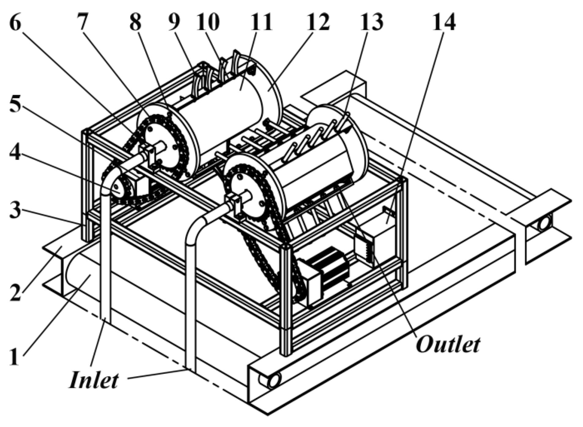
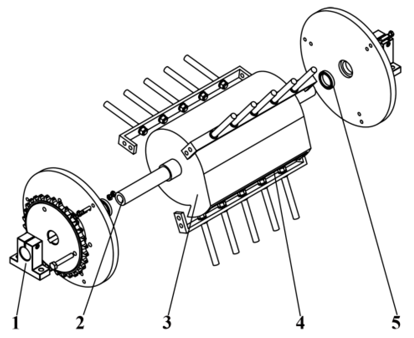
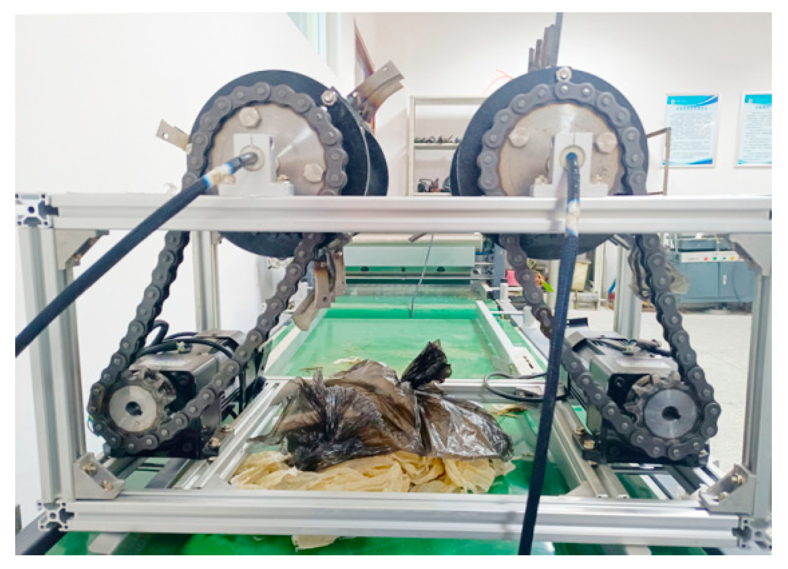
2.1. Whole Machine Structure

The whole structure of the internal blowing anti-tangle domestic garbage bag-breaking device is shown in Figure 1. The device consists of: the frame, the cutter, the support frame, the air cavity axis body, the support rod, the variable speed motor, the chain drive mechanism, etc.
The inverter and the variable speed motor are mounted on the lower end of the left and right sides of the frame by bolts, respectively. The main sprocket is mounted on the front of the variable speed motor by bolts, and the driven sprocket is mounted on the front support cover by bolts. The front support cover and the rear support cover are mounted on the front and rear shoulders of the air chamber shaft body by thin-walled bearings, respectively. The cutter and the support rod are staggered and mounted on the support frame. The support frame is connected to the front and rear support cover by bolts on both sides. The support frame supports the cutter and the support rod, and limits the front and rear movement of the support cover, and it can rotate with the support cover. Therefore, the inverter can control the rotation speed of front and rear support cover, support frame, cutter and support rod by changing the speed of variable speed motor.
The air chamber shaft body is mounted between the front and rear support end caps through thin-walled bearings, and supports the rotary motion of the outer parts during the cutting process. The front side of the air chamber shaft is a hollow shaft and the rear side is a solid shaft with uniformly angled air outlets in the middle cavity of the end caps. The front side of the air chamber shaft has a hollow shaft section that is the inlet position of the entire cavity and is connected to the air pipe by the air fitting. The lowermost end of the air pipe is connected to the fan by the air fitting. Therefore, the air pressure at the air chamber shaft body outlet can be changed by adjusting the input power.

2.2. Working Principle

The working principle of the internal blowing anti-tangle bag-breaking device is shown in Figure 2. The left cutter rotates clockwise around the center point O with the rotational speed nt, and the lowermost and uppermost radii of the cutter are r and r + lt, respectively. The right support rod rotates around its center point O` with the rotational speed ns in the counterclockwise direction, and the lowermost and uppermost radii of the support rod are r and r + ls, respectively.
When the bagged garbage is fed from the upper side, the right support rod supports the garbage bag. The left cutter, with the higher rotational speed, will continuously reduce the relative distance with the right support rod in the Y-axis direction, for breaking of the garbage bag. Because of the arc-type edge, the cutter keeps the arc-shaped line in contact with the outer surface of the garbage bag all the time, and when approaching the Y-axis direction of the support rod, the cutter squeezes and cuts the plastic film with relative sliding rotation in the local range, which has better bag-breaking effect.
At the same time, to solve the problem of the winding of the bag film in breaking, the internal air blowing cavity is set. The structure of the cavity section is shown in section view of Figure 2; the short blue line represents the internal air flow trajectory of the cavity. When the air pump sends air from the inlet position into the cavity, the air comes along the inner spiral cavity structure for full diffusion and goes out of outlet. When the cutter and the support rod carry the rotating film to the outlet area, the film is subjected to the air blowing force continuously.
The starting position of the air outlet is set on the extension line at the bottom of the cutter on vertical direction, and the ending position of the air outlet is set on the extension line at the farthest end of the cutter with an angle of 30° between the vertical direction. When the cutter passes through this area, the centrifugal force of the bag film by the rotary motion of the cutter, the gravity of the bag film and the air blowing force of the bag film at the air outlet act simultaneously to manage the problem of the winding of the bag film on the cutter.
The support rod end follows the same principle as the cutter end.

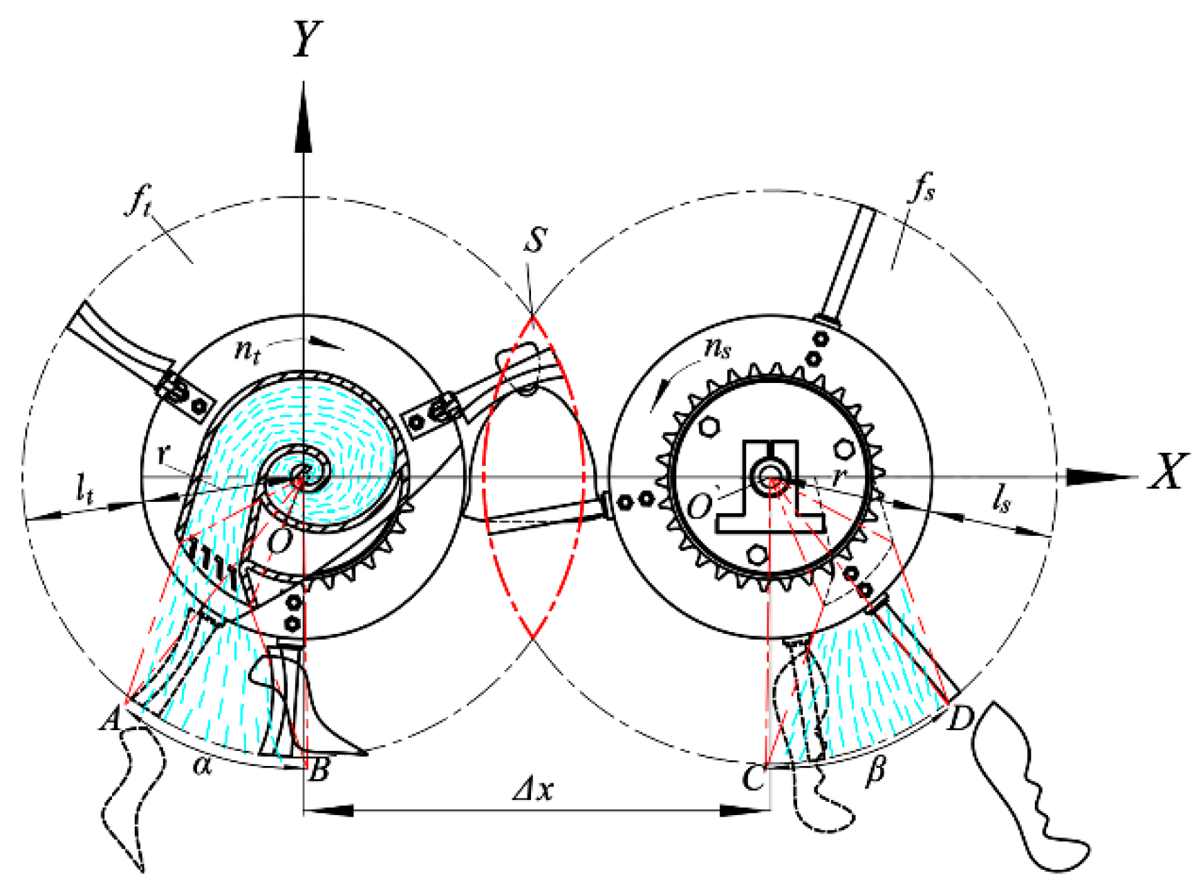
2.3. Trajectory Analysis

In order to study the effective operation area in breaking of plastic bag, the cutter and the support rod rotary motion trajectory is analyzed. As shown in Figure 2, the cutter and the support rod are in rotary motion around the point O and the point O`, respectively, in the XOY plane, so the coordinate of the rotary running trajectory of the cutter blade is:
f t ( x , y ) = ( x 1 , ± R 1 2 x 1 2 ) , x 1 [ R 1 , R 1 ] , R 1 [ r , r + l t ]
The coordinate of the rotation trajectory of the support rod is:
f s ( x , y ) = ( x 2 , ± R 2 2 x 2 2 ) , x 2 [ Δ x R 2 , Δ x + R 2 ] , R 2 [ r , r + l s ]
Then the intersection region is:
f t ( x , y ) = f s ( x , y )
To sum up the analysis, when Δx − r − ls < x < r + lt, the running trajectories of the cutter and the support rod coincide with each other, and the effective cutting of the material can be realized. The overlapping area of the cutting trajectory is:
S = 2 Δ x R 2 Δ x R 2 2 x 2 d x + 2 Δ x R 1 R 1 2 x 2 d x
where R1 and R2 are the radius from the upper and lower ends of the cutter and support rod to the center of rotation, respectively; lt and ls are the lengths of the cutter and support rod, respectively; r is the radius of rotation of the support end cap; Δx is the center distance.
Since R1 and R2 are constants in the formula, it is still necessary to explore the influence law of the center distance Δx on the trajectory coincidence area through the bag-breaking test.

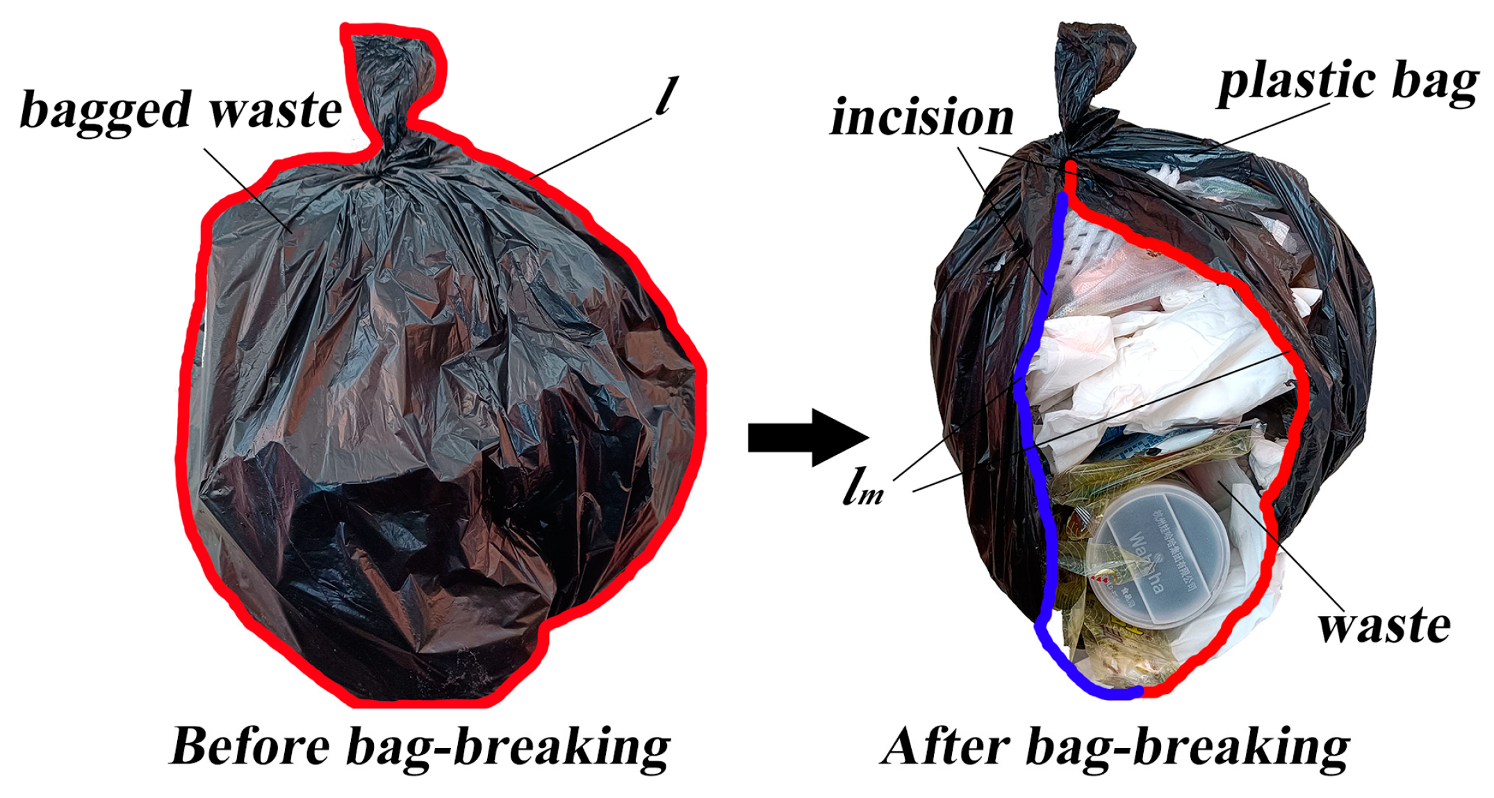
2.4. Mechanical Analysis of Garbage Bags under the Action of Different Shapes of Cutter

Under ideal conditions, the plastic bag is filled fully with domestic garbage, and the internal domestic garbage will extrude and deform each other by gravity, which will also support and extrude on the outside bag film. Due to the bag film enduring plastic deformation at this time, a smaller shear force in the normal direction of the cutter can break the bag film.
However, it was found that if the garbage bags that residents throw away still have empty space, the flexible plastic film of bag in the relaxed state is deformed with the rotary motion of the cutter, and the bag cannot be broken effectively. When using the straight cutter to break bags, as shown in Figure 3a, in the transient state, with the shearing force Fti of the cutter on different positions of the garbage bag and the horizontal direction of the same angle α, the support rod on different positions of the support force Fsi and the horizontal direction of the same angle β, then its mechanical equation is as follows:
{ Δ F x = i = 1 n F t i cos α j = 1 n F s j cos β Δ F y = G + i = 1 n F t i sin α j = 1 n F s j sin β
When the cutter turns through a certain angle, α becomes αaf and β becomes βaf, the bag is shifted to the right because of the large value of ΔFx, which makes the projection overlap between the cutter and the bag in the X direction reduce during the bag-breaking process, thus decreasing the length of the bag-breaking opening. When α tends to 0, it is shifted exactly to the rightmost side at this moment, which can not only solve the problem of the difficulty of breaking the relaxed flexible bag film, but also leads to a reduction in the bag-breaking effect.
In view of the above problems, we proposed to use the inner arc cutter for bag breaking. As shown in Figure 3b, the solid line represents the current bag-breaking state, and the dashed line represents the bag-breaking state after turning a certain angle. The cutter is always in arc contact with the bagged garbage, and the length of the arc cutter contact is greater than the line contact of the straight cutter. Because the shearing force of arc-type cutter on the bagged garbage is always toward the midpoint of the arc, the bag film in the arc contact area will be squeezed and thus broken.
The inner arc-type cutter edge, unlike the straight cutter, has different cutting angles αi between the shearing force Fti and the horizontal direction on different locations of the garbage bags, and they are symmetrical about the midpoint of the arc cutter. However, the angles β between the supporting force Fsi of the support rod in different locations and the horizontal direction are same, the mechanical formula of breaking by inner arc-type cutter edge is analyzed as follows:
{ Δ F x = i = 1 n F t i cos α i j = 1 n F s j cos β Δ F y = G + i = 1 n F t i sin α i j = 1 n F s j sin β
In this state, the splitting forces of the shearing force in the horizontal direction at the left and right arcs of the cutter will partially cancel each other out, reducing the relative slip between the cutter and the bag film. Therefore, it is only necessary to ensure ΔFy/A (cross-sectional area) > τf (the shear strength of the garbage bag film) to obtain a better bag-breaking effect.
Due to the uncertainty of the material inside the garbage bag, ignoring the gravity of the garbage bag and the internal material G, the separation force ΔFy of the combined force in the Y direction of the garbage bag-breaking process at the instantaneous moment can be obtained as follows:
Δ F y | k 1 k 2 2 π r ( P 1 sin α n 1 P 2 sin β n 2 ) |
where k1, k2 are the power transmission loss coefficient; P1, P2 are left and right motor power, respectively; α and β are cutter, support rod shearing force on the material, support force and the horizontal direction of the angle; n1 and n2 are left and right rotational speeds, respectively.
From the formula it can be seen that the rotational speeds n1 and n2 have a great impact on the value of the shearing force on the bag film, and the support motor n2 value is smaller than n1, so the value of n2 determines the minimum feeding speed. According to the previous design, n2 is takes the value of 60 r/min. The speed ratio λ = n1/n2 is introduced to indicate the speed of the system, the value of λ will have an important impact on the bag-breaking process, but its impact law still needs further experimental research.

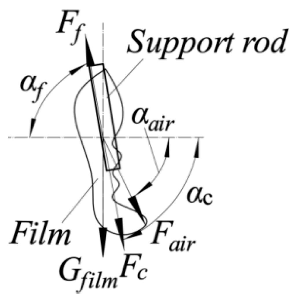
2.5. Mechanical Analysis of Air-Blown Anti-Tangle Process

An anti-tangle air chamber shaft part 3 with fixed outlet is installed inside the rotary body as shown in Figure 4. Both sides of the optical shaft support 1 can fix the air chamber shaft body 3 on the frame and it cannot be rotated. The air chamber shaft body 3 supports the outer rotary part by means of thin-walled bearings 5. Air flow enters the air chamber through the air inlet 2 and then air blows off the broken bag film passing through the area from the outlet 4. The air outlet is set at an angle as shown in AOB and CO`D in Figure 2, when the broken film wound on the cutter and support rod passes through this area, as shown in Figure 5, the resistance Ff is overcome under the joint action of air blowing force Fair, centrifugal force Fc and gravity Gfilm, and the broken film falls off, thus realizing the air blowing anti-winding function. When the broken bag film rotates to the area, the mechanical equations are as follows:
{ G f i l m + F c sin α c + F a i r sin α a i r F f sin α f > 0 F c cos α c + F a i r cos α a i r F f cos α f > 0
where Fair, Fc, Gfilm and Ff are the air blowing force, centrifugal force, gravity and resistance to the broken film, respectively; αc, αair and αf are the angle between the centrifugal force, air blowing force and resistance to the horizontal direction to the broken film, respectively.
Analysis shows that because gravity and winding resistance are difficult to control, the air blowing force and centrifugal force can be changed by adjusting the rotational speed and inlet air flow rate, so it is still necessary to further study the effect of rotational speed ratio and inlet air flow rate on the air blowing and anti-winding effect.

3. Test Design

3.1. Test Methods and Response Indicators

After building an in-blow anti-tangle domestic waste bag-breaking device, bag-breaking tests were conducted in the precision agriculture technology and equipment laboratory of Beiyuan New District, Shihezi University, Shihezi, China. The test materials were selected from the bagged domestic waste of residents in Tianfu Mingcheng, 40th community of Shihezi (longitude: 86.07° E, latitude: 44.30° N).
Randomly selected uniformly sized bags of domestic garbage parcels were chosen. Before conducting the test, the bags of domestic garbage were checked to prevent them from having a poor bag-breaking effect and not being strong enough so that they would become knotted in the breaking process. Then the surfaces of the garbage bags were manually cleaned in pool to prevent the test results from being inaccurate due to there being other wastes on the surface. After the above treatment, the bag-breaking test was performed. The main instruments and equipment used in the test process included: domestic garbage bag-breaking device (homemade), JA4100 electronic balance, tape measure and marker, etc.
During the bag-breaking test, the bag-breaking device was firstly turned on, and after the device ran smoothly, the bagged garbage was fed from directly above the device as shown in Figure 6. After the bag-breaking process, the broken materials at the outlet of the device were manually sampled and sorted. Then the domestic waste was removed. Then the inner and outer surfaces of the ruptured garbage bags and the wound shredded film were washed and dried manually, and then weighed and recorded. The comparison effect before and after the bagged garbage breaking process is shown in Figure 7.
Aiming at the bag-breaking effect of the break device on the bagged domestic garbage, the y1 bag film length–perimeter ratio was used as the response indicator. Before the bagged domestic garbage was fed, the maximum circumference of the bagged garbage through the knotted area was measured using a tape measure and recorded as l. At the end of the breaking test, the maximum length of the bag film incision after breaking was measured using a tape measure and recorded as lm. The response indicator, the y1 bag film length–perimeter ratio, is as follows:
y 1 = l m l × 100 %
Aiming at the air-blown anti-winding effect in the bag-breaking process, the y2 bag film winding specific gravity was used as the response indicator. At the end of the bag-breaking test, the broken film wound on the cutter and the support rod was weighed and recorded as m1, and the broken garbage bag was weighed and recorded as m2. The response indicator, y2 winding bag film specific gravity, is as follows:
y 2 = m 1 m 1 + m 2 × 100 %
According to the preliminary investigation and research, when (a) the cutter–support rod speed ratio λ is 3~7, (b) the center distance Δx is 240~280 mm and (c) the inlet flow rate Q is 3.2 m3/min~6.4 m3/min, the garbage bag-breaking effect and anti-tangling effect are better.
We used the above factors (a), (b) and (c) as the key factors of the test process, and carried out a three-factor, five-level orthogonal test with y1 bag film length–perimeter ratio and y2 bag film winding specific gravity as the response indicators. In addition, we designed a three-factor, five-level orthogonal test table as shown in Table 1 by using the central combination design (CCD) module in Design–Expert: the test consisted of 14 groups of analysis factor tests and 5 groups of central zero estimation errors, with a total of 19 groups.

3.2. Analysis of Results

3.2.1. Regression ANOVA and Model Construction

Regression ANOVA was performed on the experimental results in Table 1 by using the Analysis module in Design–Expert, and the analysis results are shown in Table 2.
From the results of the regression ANOVA of the test response indicator y1 in Table 2, it is clear that the p-values of the interaction terms a2 and b2 are less than 0.01, which are highly significant influencing factors for y1. The p-values of the single-factor terms a and b as well as the interaction term ab are in the range of 0.01 to 0.05, which are significant influencing factors for y1. Ignoring the nonsignificant influencing factors of the test response indicator y1, according to the p-value significance, the highly significant and significant factor terms for y1 are ranked as: a2 = b2 > a > ab > b.
From the results of the regression ANOVA of the test response indicator y2 in Table 2, it is clear that the p-values of the interaction terms bc, b2 and c2 are less than 0.01, which are highly significant influencing factors for y2. The p-values of the single-factor terms b and c are in the range of 0.01 to 0.05, which are significant influencing factors for y2. Ignoring the insignificant influencing factors of the test response indicator y2, according to the p-value significance, the highly significant and significant factor terms of y2 are ranked as: b2 = c2 > bc > b > c.
According to the results of the regression ANOVA, the second-order response models y1 and y2 constructed between the test factors such as a, b, c and the test response indicators such as y1 and y2 are:
{ y 1 = 30.88 1.15 a + 0.9 b + 0.22 c 1.23 a b 0.48 a c 0.50 b c 4.17 a 2 8.84 b 2 1.03 c 2 y 2 = 10.00 0.79 a 1.59 b 1.5 c 0.21 a b + 0.063 a c 14.81 b c + 1.05 a 2 + 7.34 b 2 + 3.79 c 2
The p-values of the model coefficients for models y1 and y2 are <0.01, indicating that the constructed second-order response models y1 and y2 are extremely significant. In addition, the coefficient of determination R2, the coefficient of correction R2adj and the coefficient of variation C.V. of model y1 are 0.9850, 0.9699 and 6.96%, respectively, indicating that the constructed model y1 has a high degree of explanation, and the model can be used to make accurate and reliable predictions of y1 values. The coefficient of determination R2, the coefficient of correction R2adj and the coefficient of variation C.V. of model y2 are 0.9621, 0.9241 and 11.71%, respectively, which indicate that the constructed model y2 has a high degree of explanation and the model can be used to make accurate and reliable predictions of y2 values.

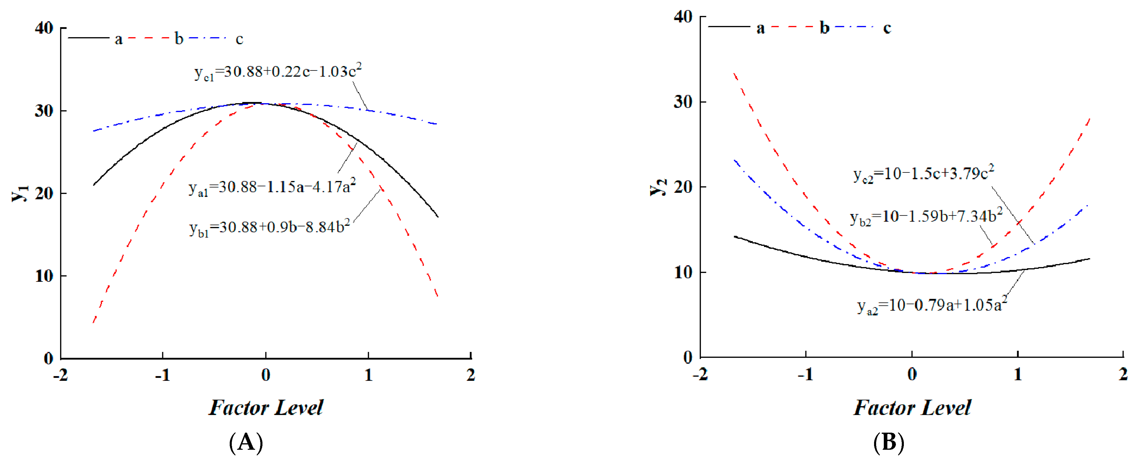
3.2.2. Single-Factor Terms on the Bag-Breaking Effect Law Analysis

In order to better observe the test factors a, b and c on the effect of the bagged domestic waste bag-breaking law, the Analysis module in Design–Expert was used to obtain the single-factor effect law on y1 bag film length–perimeter ratio and y2 bag film winding specific gravity. The single-factor term model curves redrawn by Origin data processing software are shown in Figure 7.
(1)
The influence law of single factors a, b and c on y1
In Figure 8A, ya1, yb1 and yc1 are the fitted curves of the influence law of test factors a, b and c on response indicator y1, respectively. When the level values of test factors a, b and c are between −0.5 and 0.5, the y1 bag film rupture length–perimeter ratio takes the value at the peak, where the level of factor a tends to −0.140, the level of factor b tends to 0.052 and the level of factor c tends to 0.108, and the three curves are close to the peak of y1. When the level values of factors a, b and c converge to −1.682 and 1.682, y1 is at a lower position in all three curves, and at this time the curve yc1 > ya1 > yb1, and the steepness of the overall curve yb1 > ya1 > yc1, so the ranking of the effect of a single factor on the bag film length–perimeter ratio is: b > a > c.
(2)
The influence law of single factors a, b and c on y2
In Figure 8B, ya2, yb2 and yc2 are the test factors a, b, c on the response indicator y2, the influence law of the fitting curve, respectively. When the level values of test factors a, b and c are between −0.5 to 0.5, y2 the winding bag film specific gravity takes a value in the valley, where the level of factor a tends to −0.372, the level of factor b tends to 0.108 and the level of factor c tends to 0.196, and the three curves are close to the y2 valley value. When the level values of test factors a, b and c converge to −1.682 and 1.682, y2 is in a higher position in all three curves; at this time the curve yb2 > yc2 > ya2, and the steepness of the overall curve is yb2 > yc2 > ya2, so the ranking of the effect of a single factor on the winding bag film specific gravity is: b > c > a.

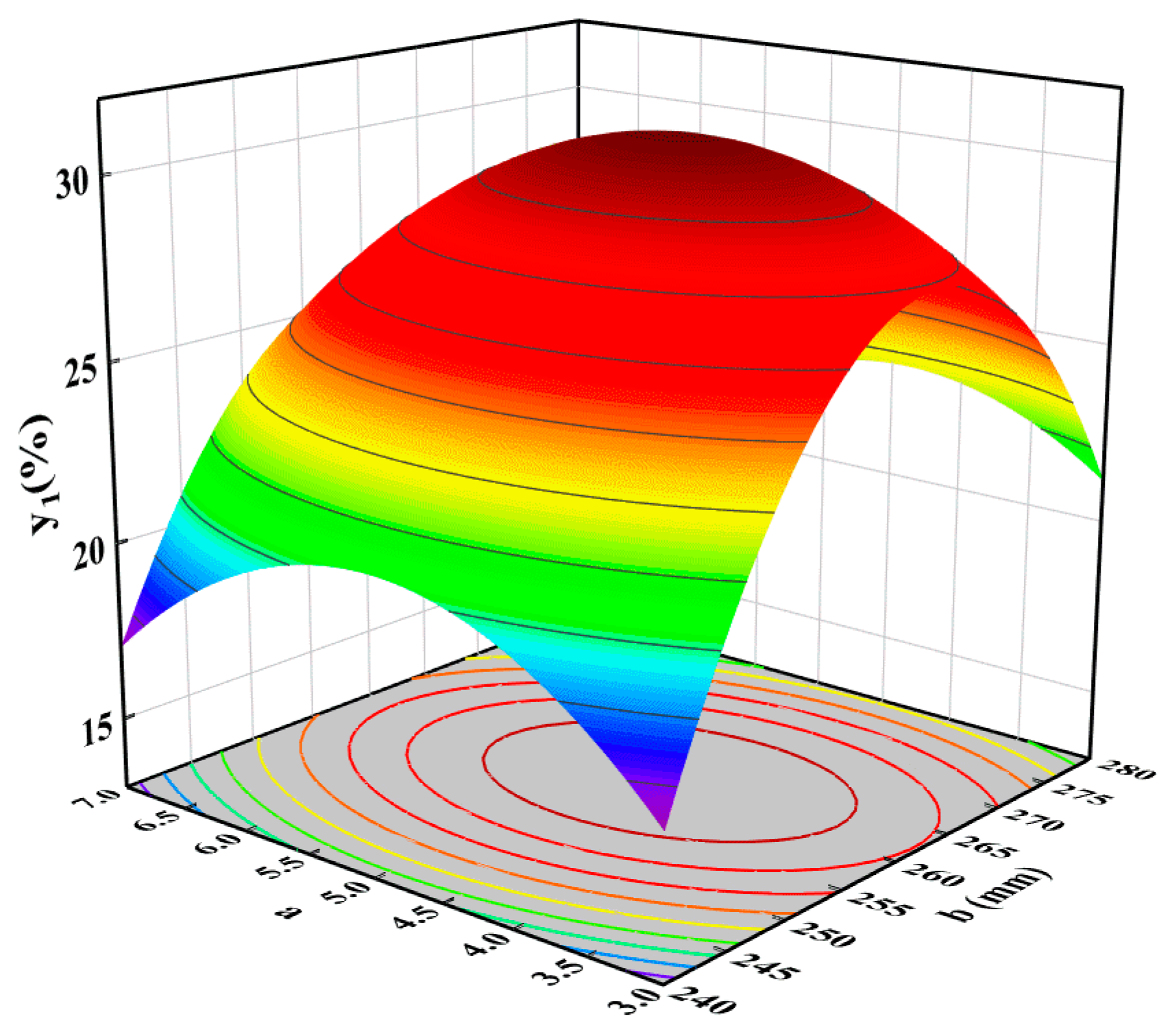
3.2.3. Influence Law of Significant Interactive Factor on the Effect of Bag Breaking

From the regression ANOVA in Table 2, it can be seen that the interaction factor ab is a significant influencing factor for the test response indicator y1. The interaction factor bc is a highly significant influencing factor for the test response indicator y2. Ignoring the insignificant interaction factor, only the highly significant and significant interaction factors were analyzed for their influence on the test response indicators y1 and y2.
(1)
Analysis of the influence law of significant interaction factors on response indicator y1.
The response surface of the significant interaction factor ab on the response indicator y1 is shown in Figure 9, with a speed ratio λ of 3.0 to 7.0, b center distance Δx of 240 to 280 mm and corresponding factor levels of −1 to 1.
When the level value of the test factor a was −1 and the level value of test factor b was incremented from −1 to 1, that is, when the speed ratio λ was 3 and the center distance Δx was incremented from 240 mm to 280 mm, the value of y1 first increased from 16.90% at 240 mm to 28.00% at 262 mm, and then gradually decreased to 21.16% at 280 mm, showing an increasing and then decreasing trend, and the increasing trend was slightly greater than the decreasing trend. When the level value of test factor a was 1 and the level value of test factor b increased from −1 to 1, that is, when the speed ratio λ was 7 and the center distance Δx increased from 240 mm to 280 mm, the value of y1 first increased gradually from 17.05% at 240 mm to 25.57% at 260 mm and then decreased gradually to 16.41% at 280 mm, showing an increasing and then decreasing trend. The increasing and decreasing trends were similar.
Compared with the change trend of the influence law of single-factor term b on y1, the change trend of the y1 value obtained under the above conditions is more similar to single-factor term b, but the change amplitude of the y1 value under the above conditions has more of a certain gap than single-factor term b, which indicates that the influence of test factor a on the y1 value is more significant under the above conditions. In summary, it can be seen that: when the value of a speed ratio λ is low, the selection of a higher center distance Δx is beneficial to obtain a higher y1 value; when the value of a speed ratio λ is high, the selection of a moderate center distance Δx is beneficial to obtain a higher y1 value.
When the level value of test factor b is −1, and the level value of test factor a is incremented from −1 to 1, that is, when the center distance Δx is 240 mm and the speed ratio λ goes from 3 to 7, the value of y1 first increases from 16.90% at 3 to 21.15% at 5.06, and then decreases to 17.05% at 7, showing the overall trend of increasing and then decreasing, and the increasing and decreasing trends are similar. When the level value of test factor b is 1 and the level value of test factor a increases from −1 to 1, that is, when the center distance Δx is 280 mm and the speed ratio λ is increased from 3 to 7, the value of y1 first increases from 23.13% at 3 to 23.30% at 4.41, and then decreases to 16.41 at 7, showing an increasing and then decreasing trend, and the increasing trend is substantially smaller than the decreasing trend.
Compared with the trend of the influence law of the single-factor term a on y1, the change trend of the y1 value obtained under the above conditions is significantly different to the single-factor term a, indicating that the test factor b under the above conditions has a significant influence on y1. From the above analysis, it can be seen that when the center distance Δx is taken as low, the selection of a moderate speed ratio λ is favorable to obtain a higher y1 value; when the center distance Δx is taken as high, the selection of a lower speed ratio λ is favorable to obtain a higher y1 value.
(2)
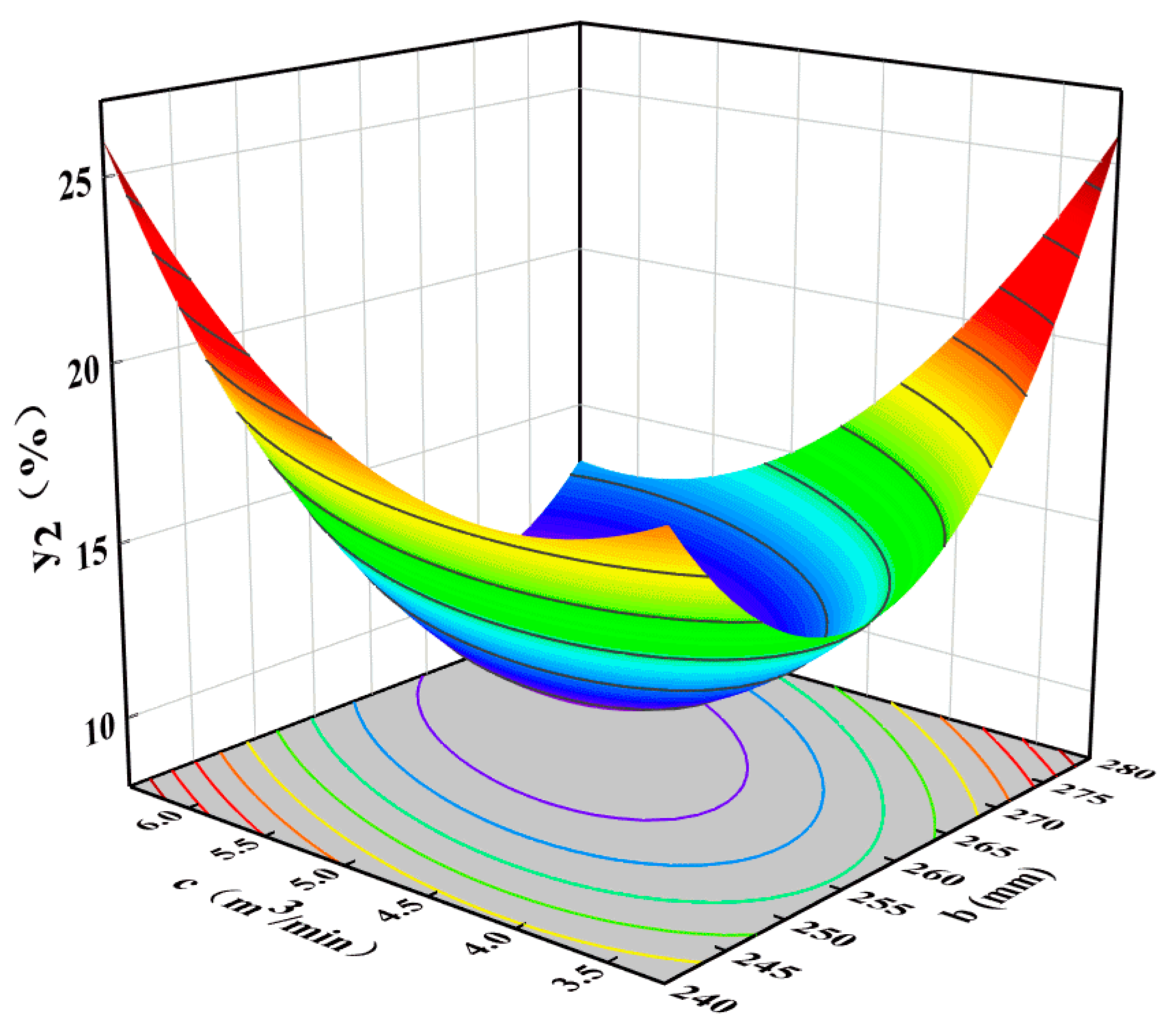
Analysis of the influence law of significant interaction factors on response indicator y2.
The response surface of the significant interaction term bc to the response indicator y2 is shown in Figure 10, with b the center distance Δx is 240–280 mm, with c the air inlet flow rate Q is 3.2–6.4 m3/min and the corresponding factor levels are −1 to 1.
When the level value of test factor b is −1 and the level value of test factor c is incremented from −1 to 1, that is, when the center distance Δx is 240 mm and the air inlet flow rate Q is incremented from 3.2 m3/min to 6.4 m3/min, the value of y2 firstly decreases from 19.39% at 3.2 m3/min to 18.19% at 4.12 m3/min, and then gradually increases to 26.01% at 6.4 m3/min, showing a trend of decreasing and then increasing, and the decreasing trend is smaller than the increasing trend. When the level value of test factor b is 1 and the level value of test factor c is incremented from −1 to 1, that is, when the center distance Δx is 240 mm and the air inlet flow rate Q is incremented from 3.2 m3/min to 6.4 m3/min, the value of y2 first decreases gradually from 25.82% at 3.2 m3/min to 13.08% at 6.09 m3/min, and then increases gradually to 13.18% at 6.4 m3/min, showing a decreasing and then increasing trend, and the magnitude of the decreasing trend is much higher than that of the increasing trend.
Compared with the change trend of the influence law of single-factor term c on y2, the change trend and magnitude of the change of the y2 value obtained under the above conditions are different from the change trend and magnitude of the influence law of single-factor term c on y2, which indicates that the influence law of test factor b on the y2 value is more significant under the above conditions. In summary, it can be seen that: when the center distance Δx is low, the lower air inlet flow rate Q is beneficial for obtaining a lower y2 value; when the center distance Δx is high, the higher air inlet flow rate Q is beneficial for obtaining a lower y2 value.
When the level value of test factor c is −1 and the level value of test factor b is incremented from −1 to 1, that is, when the c air inlet flow rate Q is 3.2 m3/min and the b center distance Δx is incremented from 240 mm to 280 mm, the value of y2 first decreases from 19.39% at 240 mm to 14.91% at 255.48 mm, and then increases to 25.82% at 280 mm, showing an overall trend of decreasing and then increasing, and the decreasing trend is slightly smaller than the increasing trend. When the level value of test factor c is 1 and the level value of test factor b is increased from −1 to 1, that is, when the air inlet flow rate Q is 6.4 m3/min and the center distance Δx is increased from 240 mm to 280 mm, the value of y2 firstly decreases from 26.01% at 240 mm to 10.85% at 268.38 mm, and then increases to 13.18% at 280 mm, showing a decreasing and then increasing trend, and the decreasing trend is substantially higher than the increasing trend.
Compared with the change trend of single-factor term b on y2, the change trend of the y2 value obtained under the above conditions is significantly different from the change trend of single-factor term b on y2, indicating that the test factor c had a significant influence on y2 under the above conditions. From the above analysis, it can be seen that: when the air inlet flow rate Q is taken as low, the selection of a lower center distance Δx is favorable to obtaining a lower y2 value; when the air inlet flow rate Q is taken as high, the selection of a higher center distance Δx is favorable to obtaining a lower y2 value.

3.2.4. Optimization of Target Parameters and Experimental Validation

In the bag-breaking process of domestic waste, the larger the bag film being broken is, the less the amount of film being wound on the mechanism is, and the more beneficial this is to the subsequent domestic waste sorting and recycling. To obtain a better bag-breaking efficiency, the key parameters such as rotational speed ratio λ, center distance Δx and air inlet flow rate Q are optimized to find the optimal combination of key parameters. The constructed quadratic regression model is optimized and analyzed using the Optimization module in Design–Expert data analysis with the following constraints:
{ max ( y 1 , y 2 ) s . t . { 3 a 7 240   mm b 280   mm 3.2   m 3 / min c 6.4   m 3 / min
According to the optimized results, the best combination of parameters was selected as follows: the predicted values of the responding indicators y1 and y2 were 30.90% and 9.67%, respectively, for the speed ratio λ of 4.91, the center distance Δx of 262.3 mm and the air inlet flow rate Q of 5.18 m3/min. In the validation test conducted in the precision agriculture technology and equipment laboratory of Shihezi University on December 16, 2022, the rotation speed ratio λ of 5.0, the center distance Δx of 260 mm and the air inlet flow rate Q of 5.2 m3/min were selected, and the analysis of the test results showed that: the bag film length–perimeter ratio y1 and the bag film winding specific gravity y2 were 29.3% and 10.5%, respectively. Compared with the corresponding model predictions, the errors between the predicted and tested values are 5.46% and 7.90%, indicating that the validation test results are basically consistent with the model predictions.

4. Discussion

(1)
The test shows that the cutting–support speed ratio λ and the center distance Δx have a significant influence on the bag film length–perimeter ratio y1. After analysis, it can be seen that when the speed ratio λ is too small, the amount of domestic garbage bags being cut is less, so the bag film length–perimeter ratio is lower and the bag-breaking effect is poor. When the speed ratio λ is too large, the cutting process of the bagged domestic garbage is too late to adjust the setting for the arc-shaped slip cutting, resulting in a poor breaking effect. When the center distance Δx is too small, the deformation space of the internal garbage bag is small, resulting in a small deformation space of the outer bag film, which leads to a poor bag-breaking effect. When the center distance Δx is too large, the overlapping area between the support rod and the cutter is small, resulting in a poor bag-breaking effect.
(2)
The test shows that the center distance Δx and the air inlet flow Q has a significant effect on the winding proportion of the bag film. When the center distance Δx is too large, the contact part with the surface of the bag film is at the top of the support rod and the top of the cutter, and the two overlapped areas are less, resulting in the top of the support rod and the top of the cutter being easily inserted into the bag, thus being easier to wind. When the center distance Δx is too small, due to the small deformation space of the garbage inside the bag, the outer bag film has a small deformation space, and the contact part with the surface of the bag film is the lower end of the support rod and the lower end of the cutter, and the tearing of the bag film is greater than the cutting behavior of the two overlapping parts, resulting in easy winding. When the air inlet flow Q is large, the airflow pressure at the outlet is large, and the anti-winding effect is better. When the air inlet flow Q is small, the airflow pressure at the outlet is small, and the anti-winding effect is poor.
(3)
This paper only studied the bag-breaking effect of the bagged domestic waste bag film breaking length–perimeter ratio and the bag film winding specific gravity, but further research is needed on the problem of the bag film breaking setting adjustment, the separation of the broken bag film, the size of the wound shredded film and the synergistic continuity of feeding and breaking.

5. Conclusions

(1)
For the technical bottleneck of bagged domestic waste bag-breaking difficulties, a rotary roller bag-breaking device based on the inner arc cutter is proposed and built. The running trajectory of the cutting parts in the bag-breaking process is analyzed theoretically, and the analysis of the bag-breaking process and the force of the anti-winding process is carried out to obtain the key parameters affecting the bag-breaking effect and bag film anti-winding.
(2)
The bag-breaking test of bagged domestic waste was carried out by the central group method, and the bag film split length–perimeter ratio and the bag film winding ratio after bag breaking were counted. The relationship model between the key parameters of the bag-breaking device and the bag film split length–perimeter ratio and its bag film winding specific gravity was constructed by using the regression ANOVA method. The model coefficients of the constructed second-order response models are p < 0.01, the coefficients of determination R2 are >0.95 and the coefficients of variation C.V are >6.96%, indicating that the constructed models are significant and have good explanatory degree, which can make an accurate and reliable prediction of the test assessment index.
(3)
Through the optimization analysis of the quadratic regression model, the best combination of parameters was obtained as follows: speed ratio of 5.0, center distance of 260 mm and inlet flow rate of 5.2 m3/min. Under the same conditions, the errors between the physical test values and model predictions were 5.46% and 7.90%, indicating that the results of the validation test were basically consistent with the model predictions.

Author Contributions

Conceptualization, M.G. and B.H.; methodology, M.G.; software, M.G.; validation, M.G. and B.H.; formal analysis, M.G.; investigation, X.L.; resources, M.G.; data curation, X.L.; writing—original draft preparation, M.G.; writing—review and editing, B.H.; visualization, M.G.; supervision, B.H.; project administration, B.H.; funding acquisition, X.L. All authors have read and agreed to the published version of the manuscript.

Funding

This research was funded by the National Natural Science Foundation of China Regional Project Fund (51865051), the Open Project of the Key Laboratory of the Modern Agricultural Machinery Corps (BTNJ2019003) and the Youth Innovation Cultivation Program of Shihezi University (KX01230202).

Institutional Review Board Statement

Not applicable.

Informed Consent Statement

Not applicable.

Data Availability Statement

The data presented in this study are available on demand from the first author at ([email protected]).

Conflicts of Interest

The authors declare no conflict of interest.

References

  1. Antonopoulos, I.; Faraca, G.; Tonini, D. Recycling of Post-Consumer Plastic Packaging Waste in the EU: Recovery Rates, Material Flows, and Barriers. Waste Manag. 2021, 126, 694–705. [Google Scholar] [CrossRef]
  2. Di Foggia, G.; Beccarello, M. An Overview of Packaging Waste Models in Some European Countries. Recycling 2022, 7, 38. [Google Scholar] [CrossRef]
  3. Li, Y.; Wang, B. Go Green and Recycle: Analyzing the Usage of Plastic Bags for Shopping in China. IJERPH 2021, 18, 12537. [Google Scholar] [CrossRef]
  4. Brady, S.; Jackson, T. Waste Recovery Using Packaging Waste Recovery Notes: A Cost-Effective Way of Meeting Targets? J. Environ. Plan. Manag. 2003, 46, 605–619. [Google Scholar] [CrossRef]
  5. Wang, B.; Li, Y. Plastic Bag Usage and the Policies: A Case Study of China. Waste Manag. 2021, 126, 163–169. [Google Scholar] [CrossRef]
  6. Ma, Y.; Koondhar, M.A.; Liu, S.; Wang, H.; Kong, R. Perceived Value Influencing the Household Waste Sorting Behaviors in Rural China. IJERPH 2020, 17, 6093. [Google Scholar] [CrossRef]
  7. Wang, B.; Zhao, Y.; Li, Y. How Do Tougher Plastics Ban Policies Modify People’s Usage of Plastic Bags? A Case Study in China. IJERPH 2021, 18, 10718. [Google Scholar] [CrossRef]
  8. John, J.; Varkey, M.S.; Podder, R.S.; Sensarma, N.; Selvi, M.; Santhosh Kumar, S.V.N.; Kannan, A. Smart Prediction and Monitoring of Waste Disposal System Using IoT and Cloud for IoT Based Smart Cities. Wirel. Pers. Commun. 2022, 122, 243–275. [Google Scholar] [CrossRef]
  9. Mmereki, D.; Baldwin, A.; Li, B.; Liu, M. Healthcare Waste Management in Botswana: Storage, Collection, Treatment and Disposal System. J. Mater. Cycles Waste Manag. 2017, 19, 351–365. [Google Scholar] [CrossRef]
  10. Sasaki, S.; Watanabe, K.; Widyaningsih, N.; Araki, T. Collecting and Dealing of Recyclables in a Final Disposal Site and Surrounding Slum Residence: The Case of Bantar Gebang, Indonesia. J. Mater. Cycles Waste Manag. 2019, 21, 375–393. [Google Scholar] [CrossRef]
  11. Muposhi, A.; Mpinganjira, M.; Wait, M. Considerations, Benefits and Unintended Consequences of Banning Plastic Shopping Bags for Environmental Sustainability: A Systematic Literature Review. Waste Manag. Res. 2022, 40, 248–261. [Google Scholar] [CrossRef]
  12. Gao, G.; Ren, Y.; Liu, Z.; Liu, S. Principle and design of flexible bag breaker on domestic waste sorting line. J. Environ. Eng. 2017, 11, 6554–6558. (In Chinese) [Google Scholar]
  13. Sheng, J.L.; Gao, Y.G.; Hao, B.B. Experimental study on the performance of municipal household waste bag-breaking and crushing machine. Environ. Sanit. Eng. 2016, 24, 38–40, 43. (In Chinese) [Google Scholar]
  14. Andrianto, M. Fahriansyah 3-D Designing of an Organic Waste Crusher. IOP Conf. Ser. Earth Environ. Sci. 2019, 277, 012009. [Google Scholar] [CrossRef]
  15. Gente, V.; La Marca, F.; Lucci, F.; Massacci, P.; Pani, E. Cryo-Comminution of Plastic Waste. Waste Manag. 2004, 24, 663–672. [Google Scholar] [CrossRef]
  16. Zhan, M.X. Sustainable Consumption and the Well-Being Dividend: Insights from the Zero-Waste Movement in Chinese Cities. Sustain. Sci. Pract. Policy 2022, 18, 731–748. [Google Scholar] [CrossRef]
  17. Nix, W.D.; Medalist, R.F.M. Mechanical Properties of Thin Films. Metall. Trans. A 1989, 20, 2217–2245. [Google Scholar] [CrossRef]
  18. Shlenskii, O.F.; Dubin, L.M. Determination of Mechanical Properties of Plastic Films? Design Calculations for Some Plastic Film Structures. Polym. Mech. 1966, 1, 110–113. [Google Scholar] [CrossRef]
  19. Zakowski, Y.; Cachera, D.; Demange, D.; Petri, G.; Pichardie, D.; Jagannathan, S.; Vitek, J. Verifying a Concurrent Garbage Collector with a Rely-Guarantee Methodology. J. Autom. Reason. 2019, 63, 489–515. [Google Scholar] [CrossRef]
  20. Jones, C.B.; Yatapanage, N. Investigating the Limits of Rely/Guarantee Relations Based on a Concurrent Garbage Collector Example. Form. Asp. Comput. 2019, 31, 353–374. [Google Scholar] [CrossRef]
  21. Wada, Y.; Okumoto, T.; Wada, N. Evaluating Household Waste Treatment Systems with Specific Examination of Collection and Transportation Processes. J. Mater. Cycles Waste Manag. 2009, 11, 82–94. [Google Scholar] [CrossRef]
Figure 1. Structure of the whole machine, consisting of the following parts: conveyor belt (1), conveyor belt table (2), machine frame (3), active sprocket (4), rear support cover (5), variable speed motor (6), chain (7), front support cover (8), cutter (9), support frame (10), air chamber shaft body (11), rear support cover (12), support rod (13), inverter (14).
Processes 11 00511 g001
Figure 2. The working principle.
Processes 11 00511 g002
Figure 3. Force and displacement diagram of bagged domestic waste. (a) The straight cutter; (b) The inner arc cutter.
Processes 11 00511 g003
Figure 4. Air chamber shaft structure and installation method.
Processes 11 00511 g004
Figure 5. Air blowing force analysis of broken bag.
Processes 11 00511 g005
Figure 6. Bench test.
Processes 11 00511 g006
Figure 7. Comparison of the effect before and after breaking.
Processes 11 00511 g007
Figure 8. The influence law of single-factor terms on response indicators: a, b and c are respectively the influence curves of the cutter–support rod speed ratio λ, the center distance Δx and the inlet flow rate Q on y. (A) y1; (B) y2.
Processes 11 00511 g008
Figure 9. The influence law of significant interaction factor ab on response indicator y1.
Processes 11 00511 g009
Figure 10. The influence law of significant interaction factor bc on response indicator y2.
Processes 11 00511 g010
Table 1. Three-factor, five-level central combination test scheme and results.
S/Nabcy1y2
1−1−1−114.123.2
21−1−115.321.7
3−11−12029.7
411−115.227.6
5−1−1117.127.9
61−1115.326.9
7−11119.915.4
811114.313.3
9−1.680021.112.7
101.680018.310.3
110−1.6805.131.7
1201.6807.926.9
1300−1.6828.319.8
14001.6828.918.7
1500030.910.7
1600033.29.6
1700028.112.3
1800031.39.1
1900030.78.8
Table 2. Regression analysis of variance of the test results.
Sourcey1y2
F-Valuep-ValueF-Valuep-Value
Model65.46<0.0001 **25.3597 <0.0001 **
a8.630.0166 *1.7514 0.2183
b5.30.0469 *7.2027 0.0250 *
c0.320.58746.4165 0.0321 *
ab5.730.0403 *0.0750 0.7904
ac0.860.37740.0065 0.9376
bc0.960.35438.4467 0.0002 **
a2113.57<0.0001 **3.1117 0.1116
b2509.51<0.0001 **152.6593 <0.0001 **
c26.880.0277 *40.6469 0.0001 **
Lack of Fit0.330.87083.4627 0.1262
R2 = 0.9850
R2Adj = 0.9699
C.V. = 6.96%
R2 = 0.9621
R2Adj = 0.9241
C.V. = 11.71%
Note: ** refers to extremely significant factor (p ≤ 0.01), * refers to significant factor (0.01 < p ≤ 0.05) and p > 0.05 refers to nonsignificant factor.
Disclaimer/Publisher’s Note: The statements, opinions and data contained in all publications are solely those of the individual author(s) and contributor(s) and not of MDPI and/or the editor(s). MDPI and/or the editor(s) disclaim responsibility for any injury to people or property resulting from any ideas, methods, instructions or products referred to in the content.

