Article

An Effective Methanol-Blocking Cation Exchange Membrane Modified with Graphene Oxide Nanosheet for Direct Methanol Fuel Cells

by
Asmaa Attya Shalaby
1,
Andrew N. Aziz
2,3,
Zdenko Špitalský
4,*,
Ahmed Mohamed Omer
5,
Mohamed Samir Mohy-Eldin
5 and
Randa Eslah Khalifa
5,*
1
Basic Science Department, Alexandria Higher Institute of Engineering & Technology (AIET), Alexandria 21311, Egypt
2
School of Engineering, University of Birmingham, Edgbaston, Birmingham B15-2TT, UK
3
Computer-Based Engineering Applications Department, Informatics Research Institute, City of Scientific Research and Technological Applications (SRTA-City), New Borg El Arab, Alexandria 21934, Egypt
4
Polymer Institute, Slovak Academy of Sciences, Dúbravská cesta 9, 845 41 Bratislava, Slovakia
5
Polymer Materials Research Department, Advanced Technologies and New Materials Research Institute (ATNMRI), City of Scientific Research and Technological Applications (SRTA-City), New Borg El-Arab City, Alexandria 21934, Egypt
*
Authors to whom correspondence should be addressed.
Processes 2023, 11(2), 353; https://doi.org/10.3390/pr11020353
Submission received: 18 December 2022 / Revised: 13 January 2023 / Accepted: 18 January 2023 / Published: 22 January 2023
(This article belongs to the Special Issue Green Processes for Sustainable Fuel Production)

Abstract

:
Herein, graphene oxide nanosheets (GO) were synthesized and employed as an additive at various proportions to fabricate a novel cation exchange membrane based on grafted cellulose acetate with sodium 4-styrenesulfonate (GCA) via a solution casting method for direct methanol fuel cell (DMFC) applications. The structure of composite membranes has been examined using FTIR, TGA, SEM, and DSC. The physicochemical properties of the GCA/GO membranes, such as ion exchange capacity, water uptake, mechanical and chemical stability, methanol permeability, and proton conductivity, were measured. The inclusion of GO significantly improved the ability to block methanol, contributing to the observed effects. Among the several composite membranes developed, GCA/GO (2 wt.%) had the highest selectivity with a water uptake of 45%, proton conductivity of 5.99 × 10⁻³ S/cm, methanol permeability of 1.12 × 10⁻⁷ cm2/s, and electrical selectivity of 26.39 × 10³ Ss/cm3. Simultaneously, the composite membranes’ mechanical, oxidative, and thermal stabilities were also enhanced. Single-cell estimation using a 2 wt.% GO modified membrane demonstrated a maximum power density of 31.85 mW.cm−2 at 30 °C. Overall, these findings highlight the perspective of the application of these developed membranes in the DMFC.

1. Introduction

The world is in the midst of an energy crisis due to the combination of dwindling fossil fuel supplies and rising energy use [1]. Fuel cells (FCs) are being studied as a possible tool for solving this issue. Due to their many desirable characteristics, including low- temperature operation, simple fuel handling, high energy fuel density, low environmental impact, and the possibility of electric vehicles and portable devices, direct methanol fuel cells (DMFCs) have garnered a great deal of attention among the many types of FC [2,3]. The polymer electrolyte membrane, also known as PEM, is an essential component of the DMFC, which must satisfy several fundamental requirements to function properly [4]. These requirements include high proton conductivity, excellent chemical stability, good mechanical strength, and low methanol permeability [5,6]. As a result, many studies have contributed towards making PEM better in terms of its transport and physical qualities. Nafion®®, a perfluorinated sulfonic acid membrane, is a widely used PEM because of its excellent proton conductivity and electrochemical stability. Unfortunately, its high production cost and low mechanical strength in the hydrated condition restrict its broad application [7,8].
Polymers that contain numerous sulfonic functional groups are promising because they boost the proton conductivities of the related PEMs [9]. Because of its relatively high proton conductivity and low cost, styrene sulfonic acid sodium salt (SSA) is a promising candidate for PEM as a replacement for Nafion. This is especially the case when combined with other polymers, such as CA, to overcome the hydrolytic instability issue of hydrophilic polymers for use as PEMs, which is a problem that can be solved through copolymerization [10]. Recent research has focused on enhancing the performance of proton exchange membranes (PEMs) by manufacturing well-defined fluoropolymer/polystyrene block copolymers and performing a sulfonation reaction to generate the appropriate sulfonated polymer structures. For example, Interial et al. [11] synthesized new polystyrene-co-acrylonitrile-co-butyl acrylate terpolymers with high proton conductivity values. Furthermore, to improve proton conductivity, thermal stability, mechanical properties, and the performance of fuel cells, poly (2,6-dimethyl-1,4-phenylene oxide)-g-poly (styrene sulfonic acid) (PPO-g-PSSA) was designed by Zeng et al. [12]. Additionally, CA was grafted using synthetic vinyl monomers such as 2-Acrylamido-2-methylpropane sulfonic acid (AMPS), Methyl Methacrylate (MMA) [13], and the effect of grafting parameters on the ion exchange capacity (IEC), and conductivity was studied.
Carbon, silica, and graphene are all examples of filler materials that can be used to enhance a material’s chemical and mechanical qualities [14]. Graphene oxide is an option for stuffing material. Because of the presence of hydroxyl, carboxyl, and epoxy groups in the hydrophilic area of graphene oxide (GO), this carbon, oxygen, and hydrogen atom compound have moderate electronic conduction but strong proton conductivity [15]. As a result of its interactions with intermolecular hydrogen bonds and the structure of membranes, GO can also improve the proton conductivities of GO-based membranes [16]. The mechanical strength of the membrane can also be improved by the presence of the sp2 carbon layer in the hydrophobic area of GO [17], which forms strong covalent bonds [12]. Mishra et al. [18] added GO with different oxidation levels to Nafion-sulfonated poly ether ether ketone (SPEEK) to investigate the impact of oxygen functionality on the physical properties of the membranes. The incorporation of various GO contents in sulfonated poly ether ether ketone was also studied by Shabani et al. [19]. The SPEEK/GO membrane was superior to the commercial membrane (Nafion117) in terms of its water uptake (WU), power density, voltage, and proton conductivity.
This feasibility research provides a novel approach to creating membrane materials for low-temperature fuel cells using a casting approach. The GO-based membranes demonstrated better mechanical properties, proton conductivity, oxidative stability, excellent methanol resistance, and good single-cell performance compared to Nafion 212. However, the performance should be briefly studied in terms of the single-cell parameters to optimize the operating parameters and obtain the maximum performance. There was a comparison of its characteristics to those of the Nafion 212 membrane. The GCA/GO composite membranes’ efficiency was evaluated in a DMFC single-cell setup. Peak power densities in the fuel cells were studied, and their correlation with the properties of GCA/GO composite membranes was analyzed.

2. Materials and Methods

2.1. Materials

Cellulose acetate powder (CA, Degree of acetylation 40%) was supplied by Sigma-Aldrich Chemie Gmbh (Louis, Mo. USA). Styrene-4-sulfonic acid sodium salt (Na-SSA, C8H7NaO3S) powder was provided by Alfa Aesar -Thermo Fisher GmbH (Kandel, Germany). Potassium persulphate (KPS, K2S2O8) (Extra Pure) was supplied from Lobachemie. Pvt. Ltd., (Mumbai, India). Pt/C catalyst (Pt content ~60 wt.%) and PtRu/C catalyst (Pt content ~40 wt.% and Ru content ~20 wt.%), Johnson Matthey (London, UK. A woven-carbon-fiber cloth without a microporous layer was provided by Ce Tech (Taichung, Taiwan). Acetone (CH3COCH3, purity 90%) was provided by Sigma-Aldrich (Louis, Mo. USA). Methanol (MeOH), ethanol, sodium hydroxide, and phenolphthalein (CH3OH, C2H6O, NaOH, and ph.ph) were purchased from Fisher Scientific (Loughborough, UK). Graphite powder and Sodium nitrate (NaNO3) were supplied by Fisher Scientific. Potassium permanganate (KMnO4) and hydrogen peroxide (H2O2, 30%W/V) were obtained from Panreac Quimica Sau (Castellar del Vallès, Spain). Iron (II) sulfate heptahydrate (FeSO4·7H2O) was acquired from Acros Organics. Hydrochloric acid (HCL purity 37%) was obtained from Polskia Odczynniki Chimiczne S.A. (Gliwice, Poland). Sodium chloride (NaCL) was analytically graded and obtained from El-Gomhouria Co. (El Matareya, Egypt). All of the chemicals and reagents employed were of analytical quality without any additional purification. Distilled and deionized water (DI) were used throughout the experiments.

2.2. Synthesis of Graphene Oxide (GO)

The synthesis of GO nanoparticles from natural graphite was conducted using a modification of Hummer’s method, as shown in our previous paper [20]. Briefly, after weighing out graphite powder (2 g) and NaNO3 (2 g), the two were combined in a volumetric flask and stirred (500 mL). After adding 150 mL of H2SO4, the liquid was agitated constantly for 30 min while placed in an ice bath (0–5 °C). Then, KMnO4 (12 g) was added, and the reaction was allowed to proceed at a temperature below 20 °C for four hours. After taking the reaction off the ice bath, it was agitated for a whole day at 35 °C, during which time the solution turned a brownish paste consistency. After that, 100 mL of DI was added to the solution to make a brownish liquid. The temperature was lowered by adding 200 mL of water. Once 10 mL of H2O2 was added to the solution, the color changed to yellow. The solution was centrifuge-purified with 5% HCl and then rinsed many times with DI. Finally, the extracted product was dried in an oven overnight at 60 °C.

2.3. Preparation of Grafted Cellulose Acetate/Graphene Oxide Composite Membranes (GCA/GO)

The grafted membrane was first prepared according to our previous work [21]. In brief, CA (10 wt.%) was magnetically stirred while being dissolved in acetone, then a fixed weight of KPS was added (0.075 g) and stirred for 10 min, followed by the inclusion of Na-SSA (1.5 g). The mixture was then reacted at 60 °C in a thermostatic water bath under a constant stirring rate of 34 rpm for 3 h. The reaction product was isolated by filtration after being precipitated in an excess of ethyl alcohol. In order to achieve a constant weight in the grafted polymer, the homopolymer was removed via multiple drying/washing cycles and ultimately dried in an oven at 60 °C. Finally, a certain weight of the grafted CA was dissolved, and the resultant homogenous solution was labeled as GCA. For the nanocomposite membranes synthesis, GO was first dispersed into acetone under ultrasonic treatment and stirred for 15 min at room temperature for uniform dispersion. Then, GCA was mixed with the suspended GO solution and stirred continuously for 24 h. The resulting solution was cast onto glass Petri dishes and dried at 50 °C for 5 h. The fabricated nanocomposite membranes were designated as GCA/GO-X, representing GO as the filler, where X indicated the filler’s weight percentage (0.05, 0.1, 0.3, 0.8, 1, and 2).

2.4. Measurements and Characterization of Membranes

The crystallinity and X-ray diffraction patterns of the synthesized GO and nanocomposite membranes were studied with an X-ray diffractometer ((XRD-6100) Shimadzu (Kyoto, Japan) using high-intensity Cu Ka radiation at 40 kV and 30 mA. An XRD pattern was obtained after a 2 h scan at a scan rate of 12°/min with an angular resolution of (0.0200).
In order to analyze the nanoscale architectures of the prepared GO filler, transmission electron microscopy (TEM) was performed on a JEOL JEM-2100F (JEOL Ltd., Shoshima, Japan) at 100 kV. The chemical structure of the created nanocomposite membranes and the functional groups of the manufactured filler was confirmed by means of Fourier-transform-infrared spectroscopy (FT-IR-8400S, Shimadzu, Japan).
GO and all the composite membranes’ surface morphology was studied using a 15 KV scanning electron microscope (SEM; JEOL JCM-6010LV, Japan). SEM examination of the fracture surfaces necessitated a gold vacuum coating. Further, a thermogravimetric analyzer TGA-50 (Shimadzu, Tokyo, Japan) was used to monitor the deterioration and stability of the fabricated membranes under heating conditions of 20 °C/min in an N2 environment from room temperature to 800 °C. Further, the degree of polymer crystallinity and glass transition temperature (Tg) of the developed composites was measured using differential scanning calorimetry (DSC) (TA Instruments Q2000, TA-Instruments-LLC, New Castle, DE, USA) at a scanning rate of 5 °C/min under an N2 atmosphere within a 25–350 °C temperature range.
The nanocomposite membrane’s IEC was determined using the titration method with HCl, NaCl, and NaOH as standard solutions [22]. The tested samples were submerged in a 1 M NaCl solution for one day at room temperature, 45, 65, and 80 °C to completely replace the H+ and were titrated using a 0.05 M NaOH solution. The reagent phenolphthalein served as the indicator. This formula was used to determine the IEC values:
I E C = V N a O H   × C N a O H m  
where IEC (meq. g−1) is the ion exchange capacity; V (ml) is the volume of NaOH consumed in titration; C (M) is the molar concentration of NaOH, and m is the mass of the dry membrane (g).
Additionally, the nanocomposite membranes’ liquid uptake was evaluated by weighing the tested sample before and after its immersion in deionized (DI) water and methanol (2 M) at room temperature, 45, 65, and 80 °C for 24 h at each temperature. The membrane swelling (SR) was calculated by comparing the dry (mdry) and wet (mwet) membrane thickness measurements. The liquid uptake and SR values of each membrane were calculated by the next expressions:
L i q u i d   U p t a k e % = m w m d m d × 100  
S R % = t w t d t d × 100  
where md and td are the weight and thickness of the dried membrane, and mw and tw are the weight and thickness of the membrane after soaking in DI and methanol.
The contact angle was measured using a contact-angle measurement apparatus (Rame-hart Instrument-Co, model (500-F1), UK). The contact angle between the water droplet and the membrane surface was determined using the sessile-drop method. The final number was determined by averaging the previous five measures in order to reduce the possibility of investigational errors.
Moreover, the oxidative stability test was conducted via Fenton’s reagent (3% H2O2 aqueous solution containing 4 ppm Fe2SO4) at 80 °C. The samples (4 cm × 4 cm) were soaked in a bath of Fenton’s reagent. The membrane’s pre- and post-immersion mass were measured. Indicators of the sample’s maximum test period included any membrane changes as it started to break or melt in the solution.
Mechanical features of the designed membranes (with a 5 cm length and 1 cm width) were measured using (LLOYD Instruments LR 10K) to evaluate the mechanical strength. Tensile deformation was determined at room temperature at a crosshead speed of 5 mm.min−1. The average results of each test, which were administered at least three times, are given.
The methanol permeability was assessed by a homemade diffusion cell that contained two compartments, one of them stuffed with DI (compartment A) while the other contained 2 M aqueous MeOH solution (compartment B) [23]. The membrane separated the two magnetically mixed spaces vertically. A sample solution (500 µL) was taken from the water compartment at regular intervals (every 30 min for 5 h) using a micro-syringe at 25 °C. HPLC analysis determined the exact methanol content. The membrane permeability was calculated using the following equation:
ρ = α V B A × L C A  
where α is the slope of the linear relation between the methanol concentration (CB) and time (t). CA refers to the initial MeOH concentration, VB to the volume of the water compartment, L to membrane thickness, and A to the membrane’s effective surface area.
To determine the proton conductivity (PC), an impedance analyzer (Solartron Analytical, 1260 FRA) was used in conjunction with potentiates (Solartron Analytical, 1287). For AC impedance, a sinusoidal signal with a 10 mV rms amplitude was applied across a frequency range of 1 MHz–10 Hz. The lateral impedance measurements were taken with a two-electrode platinum cell mounted in an open window frame (i.e., inplane). Prior to conductivity testing, all specimens were allowed to equilibrate in DI for at least 24 h. An oven with a programmable temperature and humidity level was used to maintain steady conditions. The conductivity of the membrane was determined using the next equation:
σ = L A × R m  
where A stands for the membrane cross-section area, L is the distance between the electrodes, and Rm is the resistance.
Fuel cell performance is maximized when the membrane has both low MeOH permeability and high PC. Composite membrane performance was measured using the selectivity factor, which was determined using the given formula:
= σ ρ  
For the single-cell test, membrane-electrode-assembly (MEA) was constructed via the catalyst-coated-membrane approach (CCM) [22]. On the cathode and anode sides, a woven carbon fiber cloth was used as a gas diffusion layer (GDL) with a thickness of 330 μm. After ultrasonically dispersing the catalysts (Pt/C and PtRu/C), DI water, and isopropanol with 5 wt.% Nafion ionomers for 15 min and the resulting slurry was sprayed onto the cathode and anode sides. Both electrodes had a 5 mg/cm2 as catalyst loading and an electrode area of 5 cm2. The MEA was made by sandwiching the produced CCM between two sheets of carbon paper and pressing the mixture. At 30 °C, DMFC tests were performed by feeding the 1 M methanol solution at the anode with a flow rate of 1 mL/min and fully humidified O2 gas at a flow rate of 100 mL/min at the cathode side. Polarization curves were examined by employing an FC test station to reveal how the progression of the losses influenced FC performance (Scribner Associates Model 850e) [24,25,26]. Andrew Aziz created a model for testing and evaluating FC performance using COMSOL software, and it has been validated both experimentally and numerically by means of a single-cell facility.

3. Results and Discussion

3.1. Characterization of GO

The XRD patterns, illustrated in Figure 1a, were used to investigate the crystalline structure of GO. GO showed a characteristic peak at 2𝜃 equal to 10.94°, which corresponds to the (001) crystal plane. The layer spacing (d) of the crystal plane (001) was calculated using Bragg’s equation (2𝑑 𝑠𝑖𝑛𝜃 = 𝑛𝜆), where λ is the electrons’ wavelength (0.154 nm), and n is an integer equal to one. The inter-layer distance for GO sheets was calculated to be 0.808 nm [27], which is greater than the graphene layer’s 0.34 nm. Water molecules and other oxygen-containing functional groups discovered by FTIR enhanced the interlayer distance. This agrees with other publications [28] as a result of the complexation of oxygen-related functional groups and the total oxidation of the graphite.
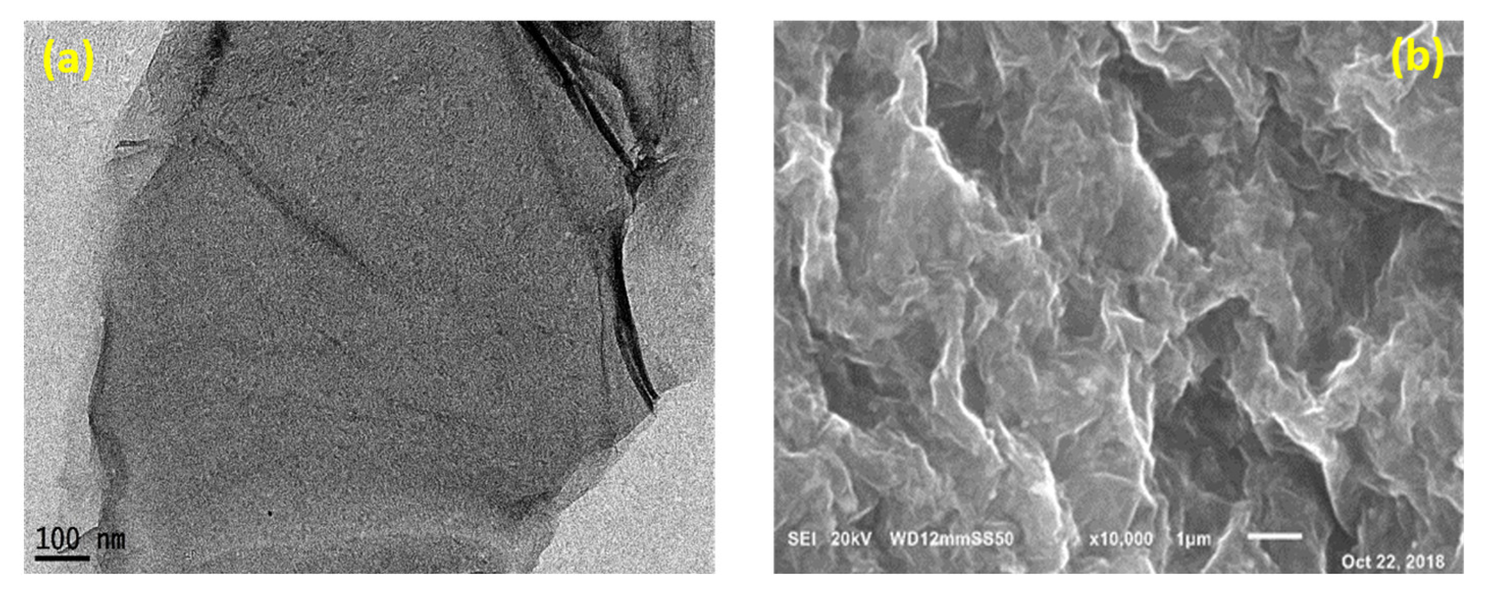
In addition, the FTIR spectrum of GO is presented in Figure 1b. The absorption peaks at 2920 cm−1 and 2856 cm−1 indicate the asymmetric and symmetric stretching vibrations of CH2 bonds, while the strong peak at 3431 cm−1 depicts the water molecules’ carboxyl groups (O-H) [29]. The peak at 1633 cm−1 is due to the ketone group (C=O), while the primary graphitic domain of the peak at 1556 cm−1 is due to sp2 hybridization [30]. The bands at 1408 cm−1 and 1238 cm−1 show the C-O stretching of epoxy groups. Alkoxy group stretching is revealed by the mode at 1050 cm−1 [31]. The absorption peak at 831 cm−1 is aromatic C-H deformation [32]. C-H bending vibrations cause spikes at 671, 565, and 463 cm−1 [28]. These findings suggest that highly oxidized and carboxyl-rich GO has been successfully produced. For the purpose of demonstrating the morphology of the obtained GO, TEM, and SEM, studies were carried out (Figure 2a,b), during which the sheet-like structure of the material was made apparent [33,34]. Table 1 lists the vibrational groups of the GO layer.

3.2. Characterization of Nanocomposite Membranes

3.2.1. FT-IR Spectroscopy

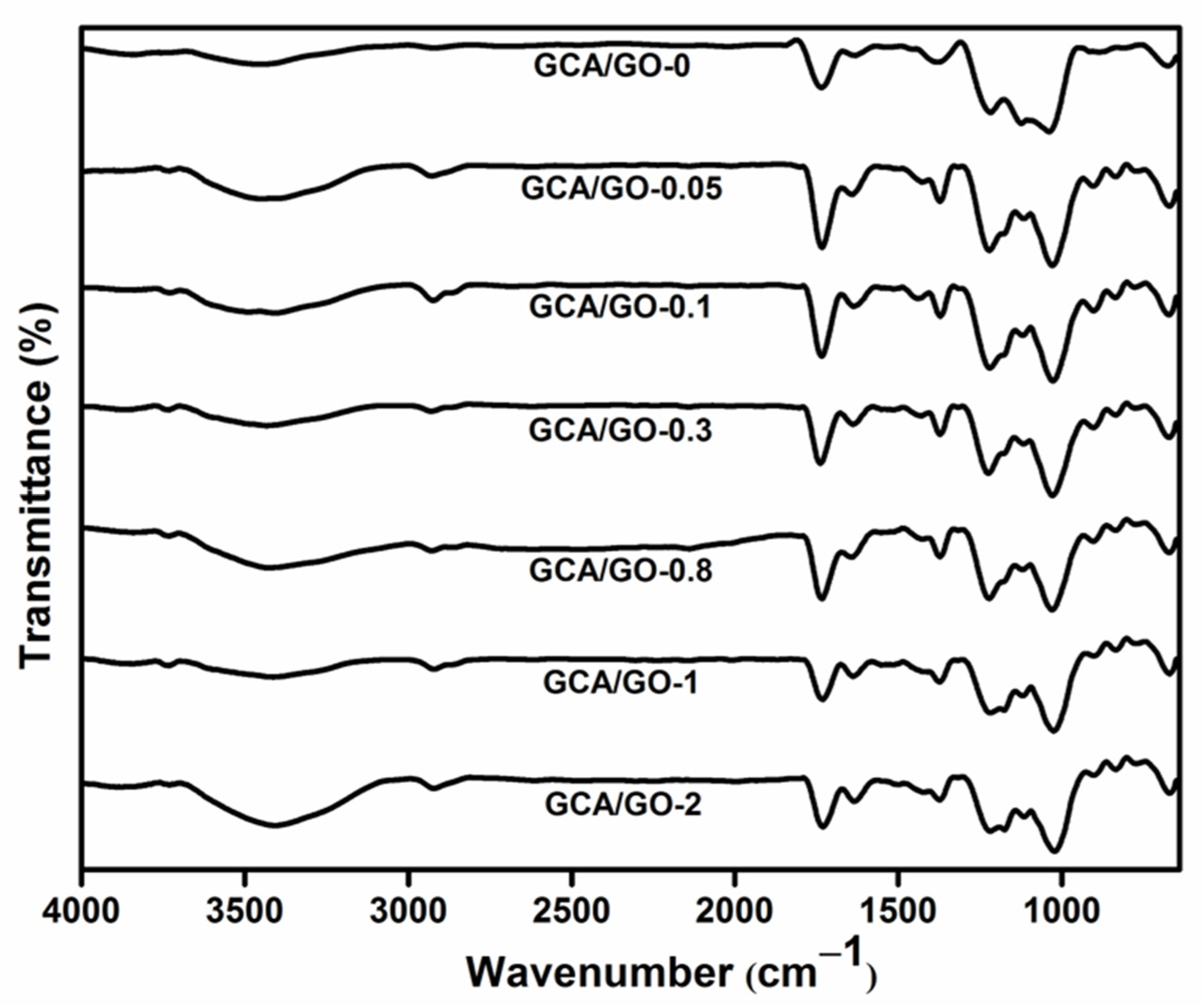
Figure 3 describes the FTIR spectra of GCA and GCA/GO membranes. For the GCA, distinct new characteristic peaks were generated at 1420 and 1370 cm−1 for the aromatic ring, as well as the out-of-plane (C-H) wagging peak for the para-substitution bands of the benzene ring at 772 and 833 cm−1. As a result of interactions with the grafted polymer, the band interrelated with sulfonate groups was moved from 1032 cm−1 to 1096 cm−1 when GO was incorporated into the polymer matrix. This amphiphilic character of GO, which consists of predominantly hydrophobic basal planes and hydrophilic edges, was credited with explaining the GO’s interactions with both the hydrophobic backbone (CA) and the hydrophilic groups (sulfonic) [2]. On the other hand, GCA/GO membranes exhibit distinctive bands attributed to the sulfonic groups at approximately 1196 and 1129 cm−1. As shown, the electrostatic force augmentation between GO and GCA causes the peak intensity of SO3H groups in nanocomposite membranes to be much lower than the unloaded grafted membrane.

3.2.2. SEM

To assess the GO dissemination, the morphology of the nanocomposite membranes was studied to learn more about the interfacial interactions between the GO and the polymer matrix. Figure 4 displays some wrinkles on the surface of the membranes. Due to the embedment of GO particles, the surface exhibits a noticeably rougher surface, indicating that the GO nanoparticles were dispersed homogeneously in the entire volume of the polymeric matrix. The cross-section images of the nanocomposite membranes display the uniform distribution of GO with scaffold-like structures (wrinkled structures). This indicates that the GO is uniformly spread throughout the polymer matrices [35,36]. This is because the oxygen functional groups (-OH, -O, -COOH) in GO and -SO3H have significant interfacial interactions (hydrogen bonding), which increase the compliance between the grafted polymer and fillers.

3.2.3. Thermogravimetric Analysis (TGA)

The thermal stabilities of the produced nanocomposite membranes are vital for the membrane’s lifetime. The TGA of GO nanoparticles and GCA/GO-0 are represented in Figure 5a. The GO curve shows the three typical phases of weight loss. The maximum initial weight loss (~4.5%) from room temperature to 100 °C is attributed to the evaporation of ingested water and other volatile matters. Then, the destruction of oxygen moieties between 100 and 200 °C causes a subsequent weight loss of roughly 50%. Furthermore, the decomposition of graphitic regions is responsible for the subsequent rapid mass loss of 70%, which was reported up to 800 °C. The GCA/GO-0 curve of the cellulose acetate grafted matrix shows characteristic weight loss stages at 100 °C, 230 °C, 470 °C, and 680 °C. In general, the GCA/GO-0 is more thermal stable than the GO up to 700 °C.
Accordingly, the thermal stabilities of GCA/GO-X membranes are also shown in Figure 5b. The TGA curves for GCA/GO nanocomposite membranes also exhibit a similar three-step weight loss characteristic indicative of the decomposition processes. Below 200 °C, the membrane’s first mass loss is caused by the evaporation of free and bound water and the remaining solvent. The pyrolysis of SO3H in chains and the degradation of acetyl groups in cellulose were responsible for the second, more dramatic weight loss, which arose between 260 and 375 °C. Finally, the third weight loss fell between 375 and 470 °C, which was linked to the oxidation of the material. The addition of GO nanosheets prevented the third degradation stage from proceeding [37]. Importantly, all nanocomposite membranes were stable below~~200 °C: a temperature range suitable for DMFCs [38]. It is worth mentioning here that the incorporation of GO with different amounts contributed to the shift of some GCA/GO-0 stages at 100 °C, 230 °C, and 470 °C and the disappearance of others at 680 °C of composite membranes with a GO content from 0.05 to 0.8%. The last degradation stage at 680 °C reappeared and was recognized at composite membranes with a GO content of 1.0% and 2.0% and shifted to a lower temperature: 600 °C. This may be referred to as the agglomeration of GO with the GCA entrapped content in the form of the core–shell. The GO shell protects the GCA core from degradation up to 600 °C. Beyond that temperature, the GCA core degrades rapidly with sharp weight loss steps. Furthermore, weight losses (T 20% and T 50%) are listed in Table 2, which may be used to quantitatively analyze the impact of GO incorporation on the thermal stability of the composite membrane.

3.2.4. Differential Scanning Calorimetry (DSC)

The introduction of GO significantly impacted pure GCA’s heating and crystallization behaviors as a filler. A DSC heating scan was performed to examine the effect of the temperature on this behavior. All polymer membranes’ glass transition temperatures (Tg) were determined using the endothermic peak of the second heating scan of the DSC curves. At low to medium temperatures, fuel cell performance was significantly impacted by the polymer membrane’s glass transition temperature. The polymer membrane’s degree of crystallinity significantly affected the Tg. The Tg of the polymer membrane is affected by its amorphous domain. Due to the loss of the amorphous domain, which in turn limits the mobility of the polymer chain and slows down the phase transition from the glassy state to the rubbery state, the membrane with a higher degree of crystallinity has a higher Tg. Figure 6 depicts the membranes’ polymer chain mobility. The GCA membrane has a Tg of 50.74 °C; the addition of GO raises the Tg of membranes, indicating that the inorganic filler limits the flexibility of polymer chains resulting in the enhancement of Tg. The GCA/GO-X membranes with a GO content of 0.05, 0.1, 0.3, 0.8, 1, and 2 wt.% show gradually enhanced Tg values of 58.60, 56.50, 223.29, 221.71, 249.64, and 243.70 °C, respectively. The results indicated that as the GO concentration increased, harder polymer chains and higher activation energies were needed to maintain the same motion state [6].

3.2.5. Ion Exchange Capacity (IEC)

The IEC can be used to figure out how many sulfonic acid groups are present in proton exchange membranes. The IEC properties of GCA/GO membranes at varied GO concentrations and temperatures are displayed in Figure 7. The results demonstrated a significant difference in IEC between the CA, GCA, and GCA/GO membranes. Since the edges of GO sheets have -COOH and carbonyl groups, increasing the GO content resulted in a marginally higher IEC. After hydration, the -COOH groups can exist in two different forms (H+ and -COO) and supply numerous charge carriers for the composite membrane, which can increase its IEC. However, greater amounts of GO decrease the -SO3H concentration and then reduce the IEC value of the composite membranes.

3.2.6. Liquid Uptake and Swelling Ratio

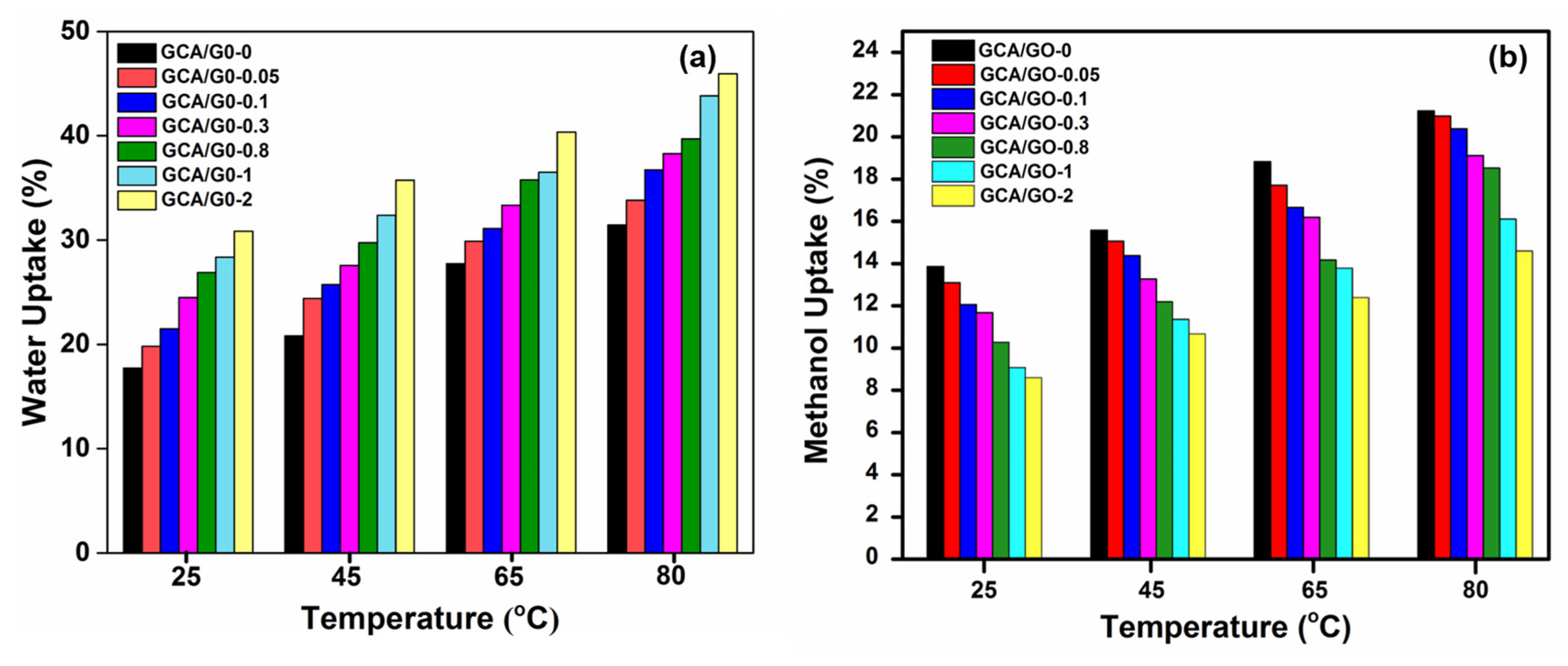
The membranes’ hydrophilic properties are primarily determined by their ability to absorb liquids (water or methanol) and their swelling ratio. Most proton-conductive polymers depend on water to transport proton ions across membranes; however, excessive water can cause the material to become dimensionally unstable [39]. Therefore, increases in the weight fraction of the hydrophilic GO content were shown to increase the water absorption (WU) of composite membranes (Figure 8a). In addition, functional groups in the incorporated fillers (sulfonic groups in the P(Na-SSA) matrix and -OH groups in GO) improved the composite membranes’ ability to absorb water [40]. Furthermore, by incorporating GO into the grafted polymer matrix, both significant structural stability and minimal MeOH uptake (MU) could be achieved; the hydrophobic segments of the GO could act as a barrier, lowering the amount of MeOH absorbed, as can be seen in Figure 8b.
On the other hand, as the temperature was raised, the liquid uptakes of the GCA/GO nanocomposite membranes also rose. Because the interaction between GO and the polymeric chains was boosted at high temperatures, this led to a larger free volume and a greater capacity to absorb liquid. This behavior may be because at high operating temperatures, the interactions between GO and polymeric chains are enhanced, and the free volume in the nanocomposite membrane increases, thereby increasing liquid absorption. As a result, the GCA /GO nanocomposite membrane has the lowest MeOH uptake compared to the Nafion 212 membrane [16,41], which is considered one of the essential parameters for fuel cell characteristics. Furthermore, the rise in temperature also improved the rate at which MeOH was transported: a phenomenon ascribed to the enhanced kinetic-diffusion rate. It also led to relaxation and expansion in the CA backbone [42].
Sufficient solvent uptake was shown to have a close relationship with the swelling ratio. The GCA/GO nanocomposite membrane water/methanol swelling ratios were calculated, as indicated in Table 3. Because of the robust hydrogenbonding interactions created between the polymer matrix and the GO nanofillers, all the GCA/GO composite membranes showed low swelling ratio values for water despite having high water absorption values. The GCA/GO composite membranes’ dimensional stability was addressed by chain entanglements between P(Na-SSA) and matrix polymer chains. This means that the GCA/GO composite membranes are more suited for PEMFCs since they can absorb more water while expending less due to hydration. The results from the swelling ratios and methanol uptake agreed demonstrated that the exceptionally stable modified GCA/GO membranes have good MeOH blocking capabilities. Thus, the necessity for methanol stability in portable FCs has been realized.

3.2.7. Contact Angle Measurement

The contact angle is a common metric used to describe membrane hydrophilicity because it influences the flow and antifouling characteristics [43]. Contact angles as high as 60.88° were recorded with a GCA membrane (Table 4). The GCA/GO composite membranes’ contact angles were reduced after being modified with the hydrophilic GO filler, indicating an increase in water affinity and hydrophilicity. This occurs because GO contains -COOH groups; therefore, improved permeation and anti-fouling performances can be achieved by increasing hydrophilicity.

3.2.8. Oxidative Stability

The GCA/GO nanocomposite membranes’ oxidative stabilities were studied by monitoring the time required for membrane rupture following their immersion in Fenton’s solution at 80 °C. The proportion of the membrane’s original weight that was conserved is shown in Table 4. After a 60 h immersion test, the GCA membrane retained 98.88% of its initial weight. All the GCA/GO composite membranes showed longer kept time where the membrane dissolved compared to the blank grafted CA membrane; however, this percentage gradually decreased with an increasing GO content, where the reserved weight of 2 wt.% for GO was 96.98%. Hydrogen bonding between the polymer and the O2 surface functional groups of GO likely protects the polar groups of the grafted membrane from the radicals (HO and HOO) generated by Fenton’s reagent. An analysis of the weight loss percentage shows that the GCA/GO membranes are resistant to Fenton’s reagent-induced oxidation [44,45].

3.2.9. Mechanical Stability

The GCA/GO nanocomposite membranes’ mechanical properties (tensile strength and elongation at break) were tabulated in Table 5. The GCA membrane exhibits an elongation at the break of 5% and a tensile strength of 46.97 MPa. Due to the reinforcing and toughening impact of GO when uniformly distributed in the grafted CA matrix, increasing the GO concentration up to 2 wt.% can raise the tensile up to 145 MPa. This improvement can be ascribed to the creation of a potent interfacial bond between the polymer and the GO filler. This interfacial connection can also prevent the spread of microcracks, which increases the elongation at the break of the GCA/GO membranes.

3.2.10. Proton Conductivity

One of the most crucial features of PEMFC is its ability to conduct protons. Since the proton needs to dissociate from acidic groups to become mobile, proton conductivity is likely to be significantly impacted by the water content of the membranes as well [46]. This can happen by proton hopping through one water molecule onto the next (Grotthuss mechanism) or as a result of the net migration of hydronium ions (H3O+) or another gathering of H+ and water [47]. Correspondingly, PC in polymeric matrices is critically reliant on H+ emitting clusters such as -SO3H, -COOH, etc. Clearly, the material’s hydrophilicity and its ability to absorb more water improve as the number of ion-exchangeable sites grows [48]. The GCA/GO composite membrane proton conductivity is shown in Table 6. There was a clear upward trend in the PC values of the GCA/GO membranes when the GO particle weight fraction included in the GCA matrixes increased. The PC in the GCA matrix increased from 4.79 × 10⁻³ S/cm for a 0.05 wt.% GO loading to 5.99 × 10⁻³ S/cm for a 3 wt.% GO loading. Hydrophilic sites of graphene oxide nanosheets in oxygenated-functional groups linked to GO’s sp3 surfaces were responsible for attracting protons via the cleavage or creation of covalent bonds [49,50]. This process requires carefully controlled additive contents. Thus, it was observed that the GCA/GO membranes with an optimal loading amount of GO (2 wt.%) enhanced proton transport. Proton conductivity was significantly enhanced with low GO loading throughout all composite membranes, suggesting that protons migrated across the hydrogen bonds of water molecules rather than using H3O+ ions (vehicle mechanism) in the GCA/GO membranes.

3.2.11. Methanol Permeability

One of the main barriers to the commercialization of DMFC is the methanol crossover across the PEMs during the electrochemical process. This is due to the possibility that the permeating MeOH might impair the power density and fuel usage while also causing cathode catalysts to lose some of their electrocatalytic activity, which would reduce their ability to perform electrocatalysis in DMFCs. The MeOH permeability obtained from all the fabricated GCA/GO nanocomposite membranes confirmed their excellent character as PEM candidates. The membranes’ methanol permeability with various GO loadings is presented in Table 6. It is evident that the GCA/GO-modified membranes’ methanol permeability declined with an increase in GO and was one order lesser than Nafion 212 (24.9 × 10⁻⁷ cm2/s). The microstructure of these composites is responsible for their minimal permeability to methanol. In contrast to Nafion, the GCA membrane’s microstructure exhibits fewer variances in hydrophilicity/hydrophobicity (the -SO3H groups are less acidic, and the cellulosic backbone is less hydrophobic) [35].
As a result, the separation between hydrophilic and hydrophobic regions is not as strong, leading to narrower ionic channels and, in turn, directing less methanol penetration than Nafion 212 [51,52,53]. In addition, the linked hydrophilic channels were made more challenging to traverse owing to the dispersion of GO into the GCA matrix, which served as a barrier. The path of decreasing drifts in the methanol crossover was shown to be tortuous and impeded by GO on the polymer. Furthermore, the interfacial interactions between GO and the grafted polymer also decreased the permeability of methanol. The significant interfacial adhesion between GCA and GO, which impeded the creation of continuous channels in the membranes, made it much more difficult for methanol to move through the GCA/GO composite membranes, which also required rather broad hydrophilic channels for methanol transport.

3.2.12. Selectivity

Higher PC and lower MeOH permeability are two requirements for promising PEMs candidates. Therefore, the selectivity factor is more essential than the pure MeOH permeability. Increasing the selectivity of an FC improves its performance. Table 6 reveals that the selectivity of GCA/GO membranes is ten times higher than those of Nafion 212 [8,54,55], making them a promising candidate for use as a PEM. Thus, the GCA/GO composite membranes with 0.8, 1, and 2 wt.% GO loading were selected for the single-cell test, as described in the subsequent section.

3.2.13. Fuel Cell Performance

Figure 9 compares the power density and polarization curves of DMFC when constructed with the original grafted CA membrane, a chosen GO-loaded GCA membrane, and a Nafion 212. It was shown that adding GO to the GCA membrane had a favorable effect on proton conductivity and enhanced water uptake, oxidative stability, and mechanical properties. Furthermore, the findings showed that the steady rise in the GO level from 0.8 to 2.0 wt.% led to an increase in the power density that passed the maximal at 2.0 wt.% (31.87 mW/cm2) compared to Nafion (28.96 mW/cm2). This improvement in cell performance may be attributable to the reduced MeOH crossover, which in turn may have reduced the mixed potentials at the cathode. This is because, as mentioned in the SEM section, the introduction of GO decreased the porosity of the grafted CA and replaced it with continuous and ordered cracks, which increased with the increasing GO loading. Furthermore, the agglomerates of GO at higher concentrations blocked the polymer matrix and resulted in a decreasing methanol crossover. In addition, a GCA membrane modified with 2 wt.% GO yielded the maximum open circuit voltage (OCV) at around 0.808 V. These relative values of the power density and the similarity of the single cell performance may be regarded by the fact that the single cell operated using the membrane electrode assembly; thus, the compatibility between the polymer matrix and the electrodes played an essential role in the performance behavior. Additionally, the difference in membrane thickness affected the performance overall.
On the other hand, the DMFC using the GCA/GO-2 membrane has a little greater power density and OCV compared to Nafion, even though the GCA/GO-2 membrane has a lower methanol permeability. Although incorporating GO has been shown to increase proton conduction via a membrane, the effect is barely noticeable. The poorer PC and weak interaction between the GO-scattered GCA film and the catalyst coating may be responsible for this. This, in turn, causes higher PC resistance, which counteracts the benefit of reduced MeOH permeability.

4. Conclusions

The GCA/GO composite membranes were manufactured for the first time using a simple casting approach to create innovative electrolytes for DMFC applications. Modified Hummer’s technique was successfully employed to manufacture GO nanosheets, which were then employed as a barrier to prevent fuel crossover through the GCA/GO composite membranes. The hydrophilic GO contents in the GCA/GO composite membrane boosted water uptake, which was more pronounced than it was in the unloaded GCA membrane. Furthermore, the addition of GO increased the ability of the membrane to block methanol due to its compact and tortuous structure, resulting in a reduction in fuel crossover. Additionally, incorporating the GO content increased the tensile strength of the developed composite membranes. This is because the GCA matrix and the GO nanosheet interacted strongly at their interface thanks to the hydrophobic/hydrophilic interactions making the GCA/GO composite membranes stiffer and more suitable for use at higher temperatures. At room temperature, the maximum conductivity of the proton was approximately 5.99 × 10⁻³ S/cm, which was lower than that of Nafion 212 (6.94 × 10⁻³). The maximum membrane selectivity was found for GCA/GO-2 (26.39 × 10³ Ss/cm3), which was much higher than that of Nafion 212 (2.787× 10³ Ss/cm3). Moreover, at 1 M methanol, single cell performance revealed a maximum power density of 31.85 mW.cm−2 for GCA/GO-2, which is quite higher than Nafion 212 (28.96 mW.cm−2) at 30 °C. The increment in proton conductivity, membrane selectivity, and the reduction in methanol permeability in GO-based polymer membranes emerged as a potential candidate for direct methanol fuel cell designs.

Author Contributions

Data curation and investigation, A.A.S.; validation and methodology, R.E.K. and M.S.M.-E.; software and validation, A.N.A.; review and editing-funding, Z.Š. and A.M.O.; writing—original draft preparation, A.A.S.; formal analysis and supervision, R.E.K. All authors have read and agreed to the published version of the manuscript.

Funding

This research received no external funding.

Data Availability Statement

Not applicable.

Acknowledgments

We greatly acknowledge the Polymer Materials Research Department, Advanced Technologies and New Materials Research Institute, City of Scientific Research and Technological Applications, for conducting this work. Additionally, Z.Š. would like to thank the Slovak Grant Agency for financial assistance, project VEGA 2/0051/20.

Conflicts of Interest

The authors declare no conflict of interest.

References

  1. Yogarathinam, L.T.; Jaafar, J.; Ismail, A.F.; Goh, P.S.; Bin Mohamed, M.H.; Radzi Hanifah, M.F.; Gangasalam, A.; Peter, J. Polyaniline decorated graphene oxide on sulfonated poly(ether ether ketone) membrane for direct methanol fuel cells application. Polym. Adv. Technol. 2022, 33, 66–80. [Google Scholar] [CrossRef]
  2. Choi, B.G.; Huh, Y.S.; Park, Y.C.; Jung, D.H.; Hong, W.H.; Park, H. Enhanced transport properties in polymer electrolyte composite membranes with graphene oxide sheets. Carbon N. Y. 2012, 50, 5395–5402. [Google Scholar] [CrossRef]
  3. Mohy Eldin, M.S.; Hashem, A.E.; Tamer, T.M.; Omer, A.M.; Yossuf, M.E.; Sabet, M.M. Development of cross linked chitosan/alginate polyelectrolyte proton exchanger membranes for fuel cell applications. Int. J. Electrochem. Sci. 2017, 12, 3840–3858. [Google Scholar] [CrossRef]
  4. Vinodh, R.; Atchudan, R.; Kim, H.-J.; Yi, M. Recent Advancements in Polysulfone Based Membranes for Fuel Cell (PEMFCs, DMFCs and AMFCs) Applications: A Critical Review. Polymers 2022, 14, 300. [Google Scholar] [CrossRef]
  5. Khalifa, R.E.; Omer, A.M.; Abd Elmageed, M.H.; Mohy Eldin, M.S. Titanium Dioxide/Phosphorous-Functionalized Cellulose AcetateNanocomposite Membranes for DMFC Applications: Enhancing Properties and Performance. ACS Omega 2021, 6, 17194–17202. [Google Scholar] [CrossRef]
  6. Mohy Eldin, M.S.; Abd Elmageed, M.H.; Omer, A.M.; Tamer, T.M.; Yossuf, M.E.; Khalifa, R.E. Novel proton exchange membranes based on sulfonated cellulose acetate for fuel cell applications: Preparation and characterization. Int. J. Electrochem. Sci. 2016, 11, 10150–10171. [Google Scholar] [CrossRef]
  7. Yuan, T.; Pu, L.; Huang, Q.; Zhang, H.; Li, X.; Yang, H. An effective methanol-blocking membrane modified with graphene oxide nanosheets for passive direct methanol fuel cells. Electrochim. Acta 2014, 117, 393–397. [Google Scholar] [CrossRef]
  8. Lin, C.W.; Lu, Y.S. Highly ordered graphene oxide paper laminated with a Nafion membrane for direct methanol fuel cells. J. Power Sources 2013, 237, 187–194. [Google Scholar] [CrossRef]
  9. Kamjornsupamitr, T.; Sangthumchai, T.; Youngme, S.; Martwiset, S. Proton conducting composite membranes from crosslinked poly(vinyl alcohol) and poly(styrene sulfonic acid)-functionalized silica nanoparticles. Int. J. Hydrogen Energy 2018, 43, 11190–11201. [Google Scholar] [CrossRef]
  10. Subel, B.L.; Wesdemiotis, C. Mass spectrometry analysis of poly(styrene sulfonate sodium salt), a polyanionic electrolyte. Int. J. Mass Spectrom. 2011, 301, 195–201. [Google Scholar] [CrossRef]
  11. Interial, L.G.D.; Benavides, R.; Morales-Acosta, D.; Francisco-Vieira, L.; da Silva, L. Development of Polymeric Electrolytes for Fuel Cells: Synthesis and Characterization of New Sulfonated Polystyrene-Co-Acrylonitrile-Co-Butyl Acrylate Terpolymers. Solid State Ion. 2022, 387, 116066. [Google Scholar] [CrossRef]
  12. Zeng, G.; Zhang, D.; Yan, L.; Yue, B.; Pan, T.; Hu, Y.; He, S.; Zhao, H.; Zhang, J. Design and Synthesis of Side-Chain Optimized Poly(2,6-Dimethyl-1,4-Phenylene Oxide)-g-Poly(Styrene Sulfonic Acid) as Proton Exchange Membrane for Fuel Cell Applications: Balancing the Water-Resistance and the Sulfonation Degree. Int. J. Hydrogen Energy 2021, 46, 20664–20677. [Google Scholar] [CrossRef]
  13. Mesbah, F.; el Gayar, D.; Farag, H.; Tamer, T.M.; Omer, A.M.; Mohy-Eldin, M.S.; Khalifa, R.E. Development of Highly Ionic Conductive Cellulose Acetate-g-Poly (2-Acrylamido-2-Methylpropane Sulfonic Acid-Co-Methyl Methacrylate) Graft Copolymer Membranes. J. Saudi Chem. Soc. 2021, 25, 101318. [Google Scholar] [CrossRef]
  14. Ryu, S.K.; Kim, A.R.; Vinothkannan, M.; Lee, K.H.; Chu, J.Y.; Yoo, D.J. Enhancing physicochemical properties and single cell performance of sulfonated poly(Arylene ether) (spae) membrane by incorporation of phosphotungstic acid and graphene oxide: A potential electrolyte for proton exchange membrane fuel cells. Polymers 2021, 13, 2364. [Google Scholar] [CrossRef] [PubMed]
  15. Špitalisky, Z.; Danko, M.; Mosnacek, J. Preparation of functionalized graphene sheets. Curr. Org. Chem. 2011, 15, 1133–1150. [Google Scholar] [CrossRef]
  16. Farooqui, U.R.; Ahmad, A.L.; Hamid, N.A. Graphene oxide: A promising membrane material for fuel cells. Renew. Sustain. Energy Rev. 2018, 82, 714–733. [Google Scholar] [CrossRef]
  17. Seo, D.C.; Jeon, I.; Jeong, E.S.; Jho, J.Y. Mechanical properties and chemical durability of nafion/sulfonated graphene oxide/cerium oxide composite membranes for fuel-cell applications. Polymers 2020, 12, 1375. [Google Scholar] [CrossRef]
  18. Mishra, A.K.; Kim, N.H.; Jung, D.; Lee, J.H. Enhanced Mechanical Properties and Proton Conductivity of Nafion-SPEEK-GO Composite Membranes for Fuel Cell Applications. J. Membr. Sci. 2014, 458, 128–135. [Google Scholar] [CrossRef]
  19. Shabani, M.; Younesi, H.; Rahimpour, A.; Rahimnejad, M. Upgrading the Electrochemical Performance of Graphene Oxide-Blended Sulfonated Polyetheretherketone Composite Polymer Electrolyte Membrane for Microbial Fuel Cell Application. Biocatal. Agric. Biotechnol. 2019, 22, 101369. [Google Scholar] [CrossRef]
  20. Madih, K.; El-Shazly, A.H.; Elkady, M.F.; Aziz, A.N.; Youssef, M.E.; Khalifa, R.E. A facile synthesis of cellulose acetate reinforced graphene oxide nanosheets as proton exchange membranes for fuel cell applications. J. Saudi Chem. Soc. 2022, 26, 101435. [Google Scholar] [CrossRef]
  21. Shalaby, A.A.; Abd Elmageed, M.H.; Malash, G.F.; Tamer, T.M.; Omer, A.M.; Mohy-Eldin, M.S.; Khalifa, R.E. Development of novel cellulose acetate-g-poly(sodium 4-styrenesulfonate) proton conducting polyelectrolyte polymer. J. Saudi Chem. Soc. 2021, 25, 101327. [Google Scholar] [CrossRef]
  22. Umsarika, P.; Changkhamchom, S.; Paradee, N.; Sirivat, A.; Supaphol, P.; Hormnirun, P. Proton exchange membrane based on sulfonated poly (aromatic imide-co-aliphatic imide) for direct methanol fuel cell. Mater. Res. 2018, 21, e20170823. [Google Scholar] [CrossRef] [Green Version]
  23. Li, J.; Xu, G.; Cai, W.; Xiong, J.; Ma, L.; Yang, Z.; Huang, Y.; Cheng, H. Non-destructive modification on Nafion membrane via in-situ inserting of sheared graphene oxide for direct methanol fuel cell applications. Electrochim. Acta 2018, 282, 362–368. [Google Scholar] [CrossRef]
  24. Aziz, A.; Hassab, M.; Youssef, M.E.; El-Maghlany, W.M. Performance Analysis of DMFC and PEMFC Numerically with Models Validation. Int. J. Adv. Electron. Comput. Sci. 2018, 5, 44–47. [Google Scholar]
  25. Gouda, M.H.; Elnouby, M.; Aziz, A.N.; Youssef, M.E.; Santos, D.M.F.; Elessawy, N.A. Green and Low-Cost Membrane Electrode Assembly for Proton Exchange Membrane Fuel Cells: Effect of Double-Layer Electrodes and Gas Diffusion Layer. Front. Mater. 2020, 6, 337. [Google Scholar] [CrossRef] [Green Version]
  26. Aziz, A.N.; Rabhy, O.O.; Youssef, M.E. Modeling and Experimental investigation for PEMFC to achieve high Fuel Cell performance. In Proceedings of the International Conference on New Trends for Sustainable Energy-ICNTSE, Madrid, Spain, 23–26 May 2016; pp. 228–231. [Google Scholar]
  27. Cullity, B.D.; Bernard, D. Elements of X-Ray Diffraction; Addison-Wesley Publishing Company, Inc.: Boston, MA, USA, 1978; ISBN 0201011743. [Google Scholar]
  28. Surekha, G.; Krishnaiah, K.V.; Ravi, N.; Padma Suvarna, R. FTIR, Raman and XRD Analysis of Graphene Oxide Films Prepared by Modified Hummers Method. J. Phys. Conf. Ser. 2020, 1495, 012012. [Google Scholar] [CrossRef]
  29. Sudesh; Kumar, N.; Das, S.; Bernhard, C.; Varma, G.D. Effect of Graphene Oxide Doping on Superconducting Properties of Bulk MgB2. Supercond. Sci. Technol. 2013, 26, 095008. [Google Scholar] [CrossRef] [Green Version]
  30. Abd El-Monaem, E.M.; Omer, A.M.; Khalifa, R.E.; Eltaweil, A.S. Floatable cellulose acetate beads embedded with flower-like zwitterionic binary MOF/PDA for efficient removal of tetracycline. J. Colloid Interface Sci. 2022, 620, 333–345. [Google Scholar] [CrossRef]
  31. Huang, B.; Dai, Y.; Liu, Y.; Zhang, X.; Qin, X.; Wang, J.; Cheng, H. Electronic Supplementary Information (ESI) Crystal Facets Controlled Synthesis of Graphene @TiO2 Nanocomposites by One-Pot Hydrothermal Process. CrystEngComm. 2012, 14, 1687. [Google Scholar] [CrossRef]
  32. Ramya, A.V.; Manoj, B.; Mohan, A.N. Extraction and Characterization of Wrinkled Graphene Nanolayers from Commercial Graphite. Asian J. Chem. 2016, 28, 1031–1034. [Google Scholar] [CrossRef]
  33. Mohy Eldin, M.S.; Omer, A.M.; Tamer, T.M.; Abd Elmageed, M.H.; Youssef, M.E.; Khalifa, R.E. Novel aminated cellulose acetate membranes for direct methanol fuel cells (DMFCs). Int. J. Electrochem. Sci. 2017, 12, 4301–4318. [Google Scholar] [CrossRef]
  34. Xu, Z.; Bando, Y.; Liu, L.; Wang, W.; Bai, X.; Golberg, D. Electrical Conductivity, Chemistry, and Bonding Alternations under Graphene Oxide to Graphene Transition as Revealed by in Situ TEM. ACS Nano 2011, 5, 4401–4406. [Google Scholar] [CrossRef] [PubMed]
  35. Muthumeenal, A.; Saraswathi, M.S.A.; Rana, D.; Nagendran, A. Fabrication and electrochemical properties of highly selective SPES/GO composite membranes for direct methanol fuel cells. J. Environ. Chem. Eng. 2017, 5, 3828–3833. [Google Scholar] [CrossRef]
  36. Suhaimin, N.S.; Jaafar, J.; Aziz, M.; Ismail, A.F.; Othman, M.H.D.; Rahman, M.A.; Aziz, F.; Yusof, N. Nanocomposite membrane by incorporating graphene oxide in sulfonated polyether ether ketone for direct methanol fuel cell. Mater. Today Proc. 2021, 46, 2084–2091. [Google Scholar] [CrossRef]
  37. Chen, J.; Guo, Q.; Li, D.; Tong, J.; Li, X. Properties improvement of SPEEK based proton exchange membranes by doping of ionic liquids and Y2O3. Prog. Nat. Sci. Mater. Int. 2012, 22, 26–30. [Google Scholar] [CrossRef] [Green Version]
  38. Nagarale, R.K.; Gohil, G.S.; Shahi, V.K. Sulfonated poly(ether ether ketone)/polyaniline composite proton-exchange membrane. J. Memb. Sci. 2006, 280, 389–396. [Google Scholar] [CrossRef]
  39. Ren, J.; Zhang, S.; Liu, Y.; Wang, Y.; Pang, J.; Wang, Q.; Wang, G. A novel crosslinking organic-inorganic hybrid proton exchange membrane based on sulfonated poly(arylene ether sulfone) with 4-amino-phenyl pendant group for fuel cell application. J. Memb. Sci. 2013, 434, 161–170. [Google Scholar] [CrossRef]
  40. Shukla, A.; Dhanasekaran, P.; Sasikala, S.; Nagaraju, N.; Bhat, S.D.; Pillai, V.K. Covalent grafting of polystyrene sulfonic acid on graphene oxide nanoplatelets to form a composite membrane electrolyte with sulfonated poly(ether ether ketone) for direct methanol fuel cells. J. Memb. Sci. 2020, 595, 117484. [Google Scholar] [CrossRef]
  41. Zakaria, Z.; Kamarudin, S.K. Evaluation of Quaternized polyvinyl alcohol/graphene oxide-based membrane towards improving the performance of air-breathing passive direct methanol fuel cells. Int. J. Energy Res. 2020, 44, 8988–9000. [Google Scholar] [CrossRef]
  42. Prapainainar, P.; Pattanapisutkun, N.; Prapainainar, C.; Kongkachuichay, P. Incorporating graphene oxide to improve the performance of Nafion-mordenite composite membranes for a direct methanol fuel cell. Int. J. Hydrogen Energy 2019, 44, 362–378. [Google Scholar] [CrossRef]
  43. Ayyaru, S.; Ahn, Y.H. Application of sulfonic acid group functionalized graphene oxide to improve hydrophilicity, permeability, and antifouling of PVDF nanocomposite ultrafiltration membranes. J. Memb. Sci. 2017, 525, 210–219. [Google Scholar] [CrossRef]
  44. Zakaria, Z.; Kamarudin, S.K.; Timmiati, S.N. Influence of Graphene Oxide on the Ethanol Permeability and Ionic Conductivity of QPVA-Based Membrane in Passive Alkaline Direct Ethanol Fuel Cells. Nanoscale Res. Lett. 2019, 14, 28. [Google Scholar] [CrossRef] [Green Version]
  45. He, Y.; Tong, C.; Geng, L.; Liu, L.; Lü, C. Enhanced performance of the sulfonated polyimide proton exchange membranes by graphene oxide: Size effect of graphene oxide. J. Memb. Sci. 2014, 458, 36–46. [Google Scholar] [CrossRef]
  46. Pan, J.; Chen, C.; Li, Y.; Wang, L.; Tan, L.; Li, G.; Tang, X.; Xiao, L.; Lu, J.; Zhuang, L. Constructing ionic highway in alkaline polymer electrolytes. Energy Environ. Sci. 2014, 7, 354–360. [Google Scholar] [CrossRef]
  47. Kreuer, K.-D. Conduction mechanisms in materials with volatile molecules. In Proton Conductors; Cambridge University Press: Cambridge, UK, 2010; pp. 474–486. Available online: https://www.cambridge.org/core/books/abs/proton-conductors/conduction-mechanisms-in-materials-with-volatile-molecules/61EAD073106A6589ACCD2C7D73E57EFC (accessed on 4 May 2022). [CrossRef]
  48. Cai, W.; Fan, K.; Li, J.; Ma, L.; Xu, G.; Xu, S.; Ma, L.; Cheng, H. A bi-functional polymeric nano-sieve Nafion composite membrane: Improved performance for direct methanol fuel cell applications. Int. J. Hydrogen Energy 2016, 41, 17102–17111. [Google Scholar] [CrossRef]
  49. Kumar, R.; Mamlouk, M.; Scott, K. A Graphite Oxide Paper Polymer Electrolyte for Direct Methanol Fuel Cells. Int. J. Electrochem. 2011, 2011, 434186. [Google Scholar] [CrossRef] [Green Version]
  50. Karim, M.R.; Hatakeyama, K.; Matsui, T.; Takehira, H.; Taniguchi, T.; Koinuma, M.; Matsumoto, Y.; Akutagawa, T.; Nakamura, T.; Noro, S.I.; et al. Graphene oxide nanosheet with high proton conductivity. J. Am. Chem. Soc. 2013, 135, 8097–8100. [Google Scholar] [CrossRef]
  51. Mohy Eldin, M.S.; Omer, A.M.; Tamer, T.M.; Abd Elmageed, M.H.; Youssef, M.E.; Khalifa, R.E. Development of Novel Phosphorylated Cellulose Acetate Polyelectrolyte Membranes for Direct Methanol Fuel Cell Application. Int. J. Electrochem. Sci. 2016, 11, 3467–3491. [Google Scholar] [CrossRef]
  52. Cai, H.; Shao, K.; Zhong, S.; Zhao, C.; Zhang, G.; Li, X.; Na, H. Properties of composite membranes based on sulfonated poly(ether ether ketone)s (SPEEK)/phenoxy resin (PHR) for direct methanol fuel cells usages. J. Memb. Sci. 2007, 297, 162–173. [Google Scholar] [CrossRef]
  53. Li, L.; Zhang, J.; Wang, Y. Sulfonated poly(ether ether ketone) membranes for direct methanol fuel cell. J. Memb. Sci. 2003, 226, 159–167. [Google Scholar] [CrossRef]
  54. Lei, L.; Zhu, X.; Xu, J.; Qian, H.; Zou, Z.; Yang, H. Highly stable ionic-covalent cross-linked sulfonated poly(ether ether ketone) for direct methanol fuel cells. J. Power Sources 2017, 350, 41–48. [Google Scholar] [CrossRef]
  55. Rambabu, G.; Nagaraju, N.; Bhat, S.D. Functionalized fullerene embedded in Nafion matrix: A modified composite membrane electrolyte for direct methanol fuel cells. Chem. Eng. J. 2016, 306, 43–52. [Google Scholar] [CrossRef]
Figure 1. (a) XRD and (b) FTIR of GO.
Processes 11 00353 g001
Figure 2. (a) TEM and (b) SEM image of GO.
Processes 11 00353 g002
Figure 3. FT-IR of GCA and GCA/GO nanocomposite membranes.
Processes 11 00353 g003
Figure 4. Surface and cross-sectional SEM images of GCA and GCA/GO nanocomposite membranes at different ratios of GO.
Processes 11 00353 g004aProcesses 11 00353 g004b
Figure 5. TGA curves of (a) GCA and GO and (b) GCA/GO nanocomposite membranes at different ratios of GO.
Processes 11 00353 g005
Figure 6. DSC of GCA/GO nanocomposite membranes at different ratios of GO.
Processes 11 00353 g006
Figure 7. IEC of GCA/GO nanocomposite membranes at different temperatures.
Processes 11 00353 g007
Figure 8. Water and methanol uptake% of GCA/GO nanocomposite membranes at different temperatures.
Processes 11 00353 g008
Figure 9. Polarization and power density curves of DMFC operating at 30 °C and 1 M methanol feed concentration.
Processes 11 00353 g009
Table 1. GO’s characteristic vibrational modes and energies.
Wave Number (cm−1)Functional Group
3431-H
2920CH2
2856CH2
1633C=O
1556C=C
1408 C-O
1238C-O-C
1050COOH
831C-H
671C-H
565C-H
463C-H
Table 2. TGA analysis for GCA/GO nanocomposite membranes at different ratios of GO.
MembranesT20%T50%Weight Loss (%)
at Ambient Temperature
(0–120 °C)
GCA/GO-0221.54291.9513.040
GCA/GO-0.05262.69303.854.8700
GCA/GO-0.1265.34338.405.2300
GCA/GO-0.3244.18355.478.8400
GCA/GO-0.8210.54398.2412.520
GCA/GO-1220.00408.8212. 060
GCA/GO-2235.00426.1711.220
Table 3. Dimensional changes of GCA/GO nanocomposite membranes in water and methanol at different temperatures.
MembranesDimension Changes (%)
in Water
Dimension Changes (%)
in Methanol
25 °C45 °C65 °C80 °C25 °C45 °C65 °C80 °C
GCA/GO-06.686.777.357.836.977.698.928.47
GCA/GO-0.055.555.795.825.895.176.127.327.27
GCA/GO-0.15.525.845.895.975.886.256.526.38
GCA/GO-0.35.815.956.176.195.886.526.667.14
GCA/GO-0.85.975.976.166.236.386.526.666.70
GCA/GO-16.006.286.596.635.705.705.86.00
GCA/GO-26.226.266.466.805.805. 806.006.00
Table 4. Contact angle and thermal stability of the GCA/GO nanocomposite membranes at different ratios of GO.
MembraneTime (h)Retained Weight (%) Contact Angle (°)
GCA/GO-06098.560.98
GCA/GO-0.056298.5855.77
GCA/GO-0.16597.6552.59
GCA/GO-0.37297.1447.12
GCA/GO-0.88296.8846.02
GCA/GO-18496.6740.38
GCA/GO-29596.8635.71
Table 5. The mechanical features of blank GCA membrane and GCA/GO modified nanocomposite membranes at different GO content.
MembranesTensile Strength (MPa)Elongation at Break (%)
GCA/GO-046.975.00
GCA/GO-0.0551.355.30
GCA/GO-0.157.145.76
GCA/GO-0.363.346.00
GCA/GO-0.869.406.60
GCA/GO-174.557.56
GCA/GO-279.568.71
Table 6. Characterization of the developed GCA/GO membranes.
MembranesConductivity
(S.cm−1 × 10⁻³)
Resistance
(Ω × 10−3)
Methanol
Permeability
(cm2 · s−1 × 10⁻⁷)
Electrochemical
Selectivity
(Ss · cm−3 × 10³)
CA0.035 14285.718.0000.0194
GCA/GO-04.770 104.825.5148.651
GCA/GO-0.054.790104.385.3209.004
GCA/GO-0.14.900102.043.65013.424
GCA/GO-0.35.11097.843.98012.839
GCA/GO-0.85.52090.571.47037.551
GCA/GO-15.84085.611.33043.910
GCA/GO-25.99083.471.12026.390
Nafion 2126.94072.0524.9002.7870
Disclaimer/Publisher’s Note: The statements, opinions and data contained in all publications are solely those of the individual author(s) and contributor(s) and not of MDPI and/or the editor(s). MDPI and/or the editor(s) disclaim responsibility for any injury to people or property resulting from any ideas, methods, instructions or products referred to in the content.