Article

Physical and Numerical Simulation Study on Structure Optimization of the Inner Wall of Submerged Entry Nozzle for Continuous Casting of Molten Steel

1
School of Materials and Metallurgy, University of Science and Technology Liaoning, Anshan 114011, China
2
School of Electrical and Automation Engineering, Liaoning Institute of Science and Technology, Benxi 117004, China
*
Author to whom correspondence should be addressed.
Processes 2023, 11(11), 3237; https://doi.org/10.3390/pr11113237
Submission received: 29 September 2023 / Revised: 13 November 2023 / Accepted: 14 November 2023 / Published: 16 November 2023
(This article belongs to the Special Issue Modeling, Simulation, Control, and Optimization of Processes)

Abstract

:
The submerged entry nozzle (SEN) plays an important role in the continuous casting production process. It is a cast refractory pipe fitting installed in the lower part of the tundish and inserted below the molten steel level of the mold. It not only affects the speed of molten steel flow, but is also prone to nodules and affects production. In the present work, the flow behavior of molten steel in a traditional nozzle and that in a new type of nozzle whose inner wall was distributed with arrays of hemispherical crowns were studied by means of both physical simulation (using a water model) and numerical simulation (using ANSYS CFX) based on the prototype of a production continuous casting slab mold. Both experimental and numerical simulation results show that, compared with the traditional nozzle, the impact depth generated by the new-type nozzle in the mold is reduced by 21.06–26.03 cm, the impact angle is reduced by 14–17 degrees, and swirl flow was generated inside the new-type nozzle, which not only improves the flow characteristics inside the submerged entry nozzle and changes the dead zone size in the submerged entry nozzle, but also improves the velocity distribution at the outlet of the nozzle and minimizes the possibility of nodulation. In addition, in contrast to the traditional nozzle that generates flat body-shaped jets of molten steel flow, the new-type nozzle produces baseball glove-shaped jets that penetrate shallower into the molten steel bath in the mold, which significantly reduces the outlet velocity and is conducive to the floating of inclusions.

1. Introduction

During continuous casting production, the stability of the steel flow inside the nozzle directly affects the quality of the steel slab. The rational design of the submerged entry nozzle structure and the optimization of the continuous casting process parameters play a crucial role in ensuring high-quality steel billets during continuous casting. To assess the quality of a submerged entry nozzle, it is important to consider not only its service life, but also whether a reasonable flow field can be formed in the mold under specific process conditions to meet the requirements of efficient continuous casting. In order to improve the steel slab quality and continuous casting speed, the flow characteristics of molten steel in the nozzle were studied according to the actual situation, and various optimized submerged entry nozzles designs were proposed. Through the study of the flow characteristics of molten steel inside the nozzle, the flow state of molten steel entering the mold can be improved and the bad phenomena, such as steel slag and bubbles, can be reduced. Optimizing the design of the submerged entry nozzle includes adjusting the size of the submerged entry nozzle and changing its shape. The molten steel flow pattern in the mold varies with different submerged entry nozzle structures. Therefore, many researchers used physical simulation and mathematical simulation methods to study the influence of submerged entry nozzles and mold on molten steel flow [1,2,3,4,5,6].
One type of design is to adjust the submerged entry nozzle size. Reasonable design and selection of the diameter and length of the submerged entry nozzle make the molten steel have better flow performance when entering the mold. The outlet shapes of the submerged entry nozzle are generally circular, elliptical, and rectangular. The outlet shape has minimal impact on the flow field of the mold, but affects the velocity of the stream and its scattering degree. N. Tsukamoto et al. [7] noted that the jet velocity and impact depth of the stream at the square outlet are greater than those at the circular outlet when the outlet area is the same. However, the scattering degree of the stream at the square outlet is smaller, resulting in less erosion on the narrow side of the mold. This is advantageous for promoting uniform growth of the shell. In comparison to the circular outlet, the elliptical outlet is unstable due to the significant pressure difference between its upper and lower parts. The bottom shape of the submerged entry nozzle can be categorized into three types: flat bottom type, convex type, and concave type. Water model and field tests indicate that the impact force and depth on the narrow face of the concave nozzle are significantly lower than those of the convex nozzle. Additionally, the meniscus of the mold is more active in the concave nozzle, facilitating the melting of the protective slag and improving the lubrication condition between the slab shell and the mold wall. Wenfang Gao et al. [8] suggested that the concave nozzle outperforms the convex nozzle in improving the flow field of the mold and enhancing the slab’s quality. However, the use of the concave nozzle presents certain issues, such as molten steel upturn in the mold and severe erosion of the refractory at the nozzle outlet caused by the molten steel. Another type of design can also consider using a guide device to optimize the submerged entry nozzle design. For example, Tsukaguchi [9] considered that the generation of swirling flow in the nozzle can improve the uniformity and stability of the flow at the outlet of the nozzle. Harada, T et al. [10] placed a guide device with 12 blades inside the submerged entry nozzle model, and obtained the swirling flow of molten steel in the submerged entry nozzle. The water model experiment and computational fluid dynamics (CFD) numerical simulations analysis showed that after the blade was used, the molten steel produced a swirling flow. This swirling flow can obtain a uniform and uniform flow at the outlet of the submerged entry nozzle, which has a significant effect on the fluctuation of the meniscus of the mold. It can effectively reduce the impact of the stream on the narrow side of the mold and achieve the purpose of improving the flow field of the mold. However, due to the repeated erosion of the molten steel on the blades in the nozzle, its service life will be short. X.C. Cui et al. [11] introduced an ‘X’ submerged entry nozzle with two semi-elliptical deflectors. The submerged entry nozzle incorporates a spiral diversion channel, which serves to guide the molten steel in the mold and induce rotation. This rotation of the molten steel in the vortex area facilitates the aggregation and floating of inclusion bubbles. In contrast, the low rotation speed in the weak stirring area promotes the formation of a solidified shell. The production practice of pouring with the ‘X’ type submerged entry nozzle demonstrated several advantages. It ensures uniform temperature distribution and a wide isothermal range, while minimizing temperature gradients. Additionally, it enhances the feeding capacity, facilitates the formation of equiaxed crystals, and reduces shrinkage. Moreover, the nozzle effectively inhibits the impact depth of the injection flow, thereby promoting the floating of inclusions and bubbles and the formation of a solidified shell. Consequently, the internal quality of the billet is significantly improved, and central segregation is effectively reduced. Z.J. Su et al. [12,13,14] added a magnetic field outside the submerged entry nozzle, and used the Lorentz force of the rotating electromagnetic field outside the submerged entry nozzle to make the molten steel flow spirally inside the nozzle. The results show that the electromagnetic swirl of the nozzle makes the molten steel in the round mold in a rotating state. At the same time, when there is swirl, horizontal flow can be observed near the corner of the mold. The impact depth of the molten steel is smaller and the back flow is enhanced. However, due to increased costs and a harsh working environment, further application of this method is limited.
In this research, a new method for generating swirling flow inside the nozzle by protruding hemispherical crowns on the inner wall of the nozzle, so as to prevent the nozzle from clogging and reduce the outlet steel flow velocity, was investigated through carrying out both physical model simulations and computational fluid dynamics (CFD) numerical simulations. For this, a full-scale water model equipped with a PIV measurement system was set up in a laboratory. We used ANSYS CFX to establish a computational fluid dynamics numerical model of the flow fields in the nozzle and in the slab mold. Based on the results of physical and numerical simulations, the flow states of the molten steel inside the traditional nozzle and the new-type nozzle and in the mold were analyzed and compared. The new-type nozzle can guide the molten steel into the mold in a more reasonable, smooth, and uniform way, and avoid the problems of steel slag and bubbles while ensuring the normal flow.

2. Physical Simulation Research

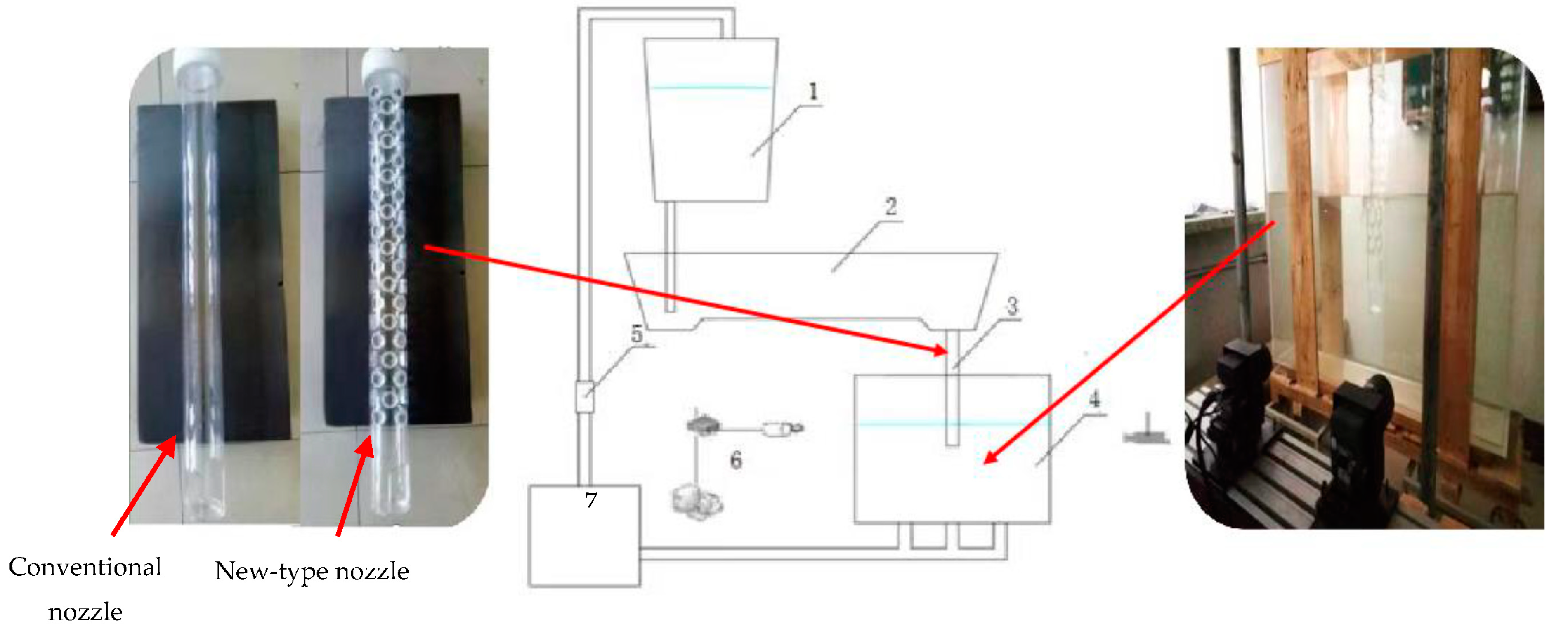
2.1. Experimental Device and Principle

The water model experimental set-up is based on a production continuous casting slab mold as the prototype, and a 1:1 full-scale physical model of the mold and the submerged entry nozzle is established. The tundish, mold, and nozzle models are all made of transparent plexiglass plates. The schematic diagram of the experimental device is shown in Figure 1. Before performing the experiment, the mold is ensured to be in a horizontal state, and the nozzle is fixed to ensure that the nozzle is perpendicular to the liquid surface level in the mold. At the same time, the plane containing axes of the two outlets of the nozzle that contain the central axis of the mold are required to be on the same vertical plane. The flowrate of the whole water circulation system is controlled to maintain a stable value by controlling the reading of the frequency conversion system and the rotameter. A particle image velocimetry (PIV) system from the TSI Corporation was used for the water model experimental measurement.
In the physical model experiment, water is used to simulate molten steel. Using physical properties of molten steel and water given in Table 1 and based on Equation (1), the flow states of molten steel and water are ensured to reach the second self-modeling zone, so that the flow velocity distributions of the fluids are similar to each other. When establishing the physical model, it is necessary to ensure the similarities in geometry, dynamics, and motion between the model and the prototype. Since molten steel and water can be regarded as viscous and incompressible fluids, their flows are mainly affected by inertial force and gravity, which need to satisfy Frp = Frm, where Fr is the Froude number defined in Equation (2). According to the mold dimensions (1800 mm in length, 1200 mm in width, and 200 mm in thickness), the water flowrate for the model is calculated to be 18.52 m3/h by using Equation (2).
R e = V L ν
where V is the fluid velocity (m/s); L the characteristic length, i.e., the vertical length of the mold (m); and ν the kinematic viscosity (m2/s).
( v steel 2 g L steel ) p = ( v water 2 g L water ) m
where the subscripts p and m stand for the parameters of prototype and model, respectively.

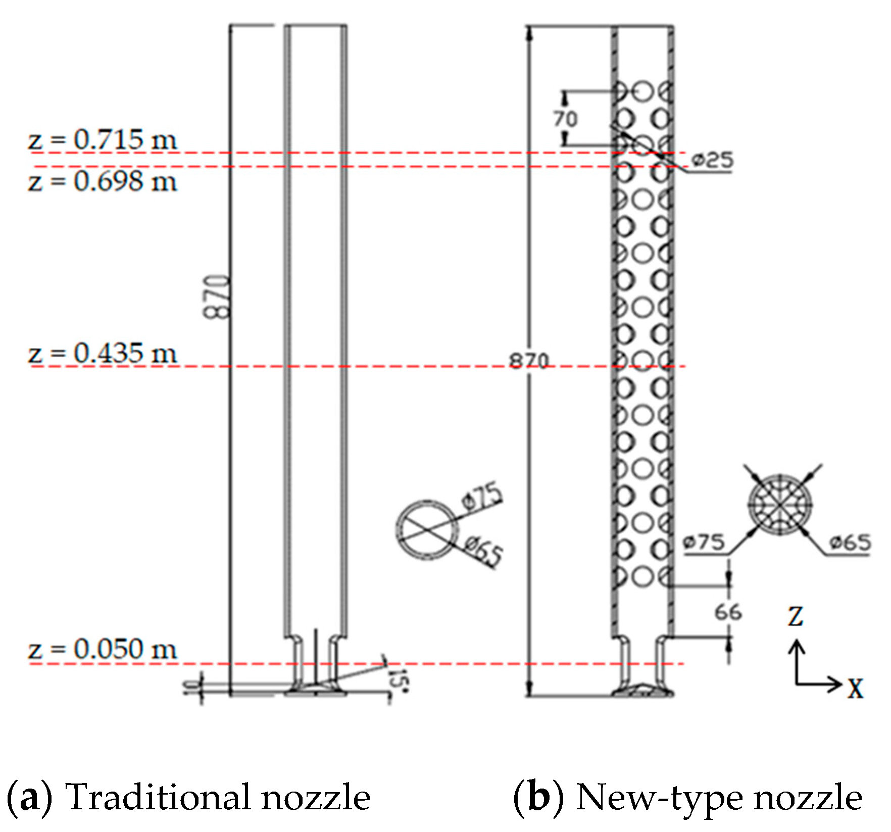
2.2. Structure of Traditional and New-Type Submerged Entry Nozzle for Continuous Casting

Figure 2 depicts structures of the traditional and the new-type submerged entry nozzles for the continuous casting of steel slabs, which are used as prototypes in this study. Both nozzles have an inner diameter of 65 mm, an outer diameter of 75 mm, and a total length of 870 mm. Different from the traditional nozzle, which is a tube with a smooth inner wall face, the new-type nozzle contains eight rows of hemispherical crowns on the inner wall. Each row has 10 hemispherical crowns with a radius of 25 mm and a spacing of 70 mm. The red line in the figure depicts the cross-sectional position of the numerical simulation experiment.

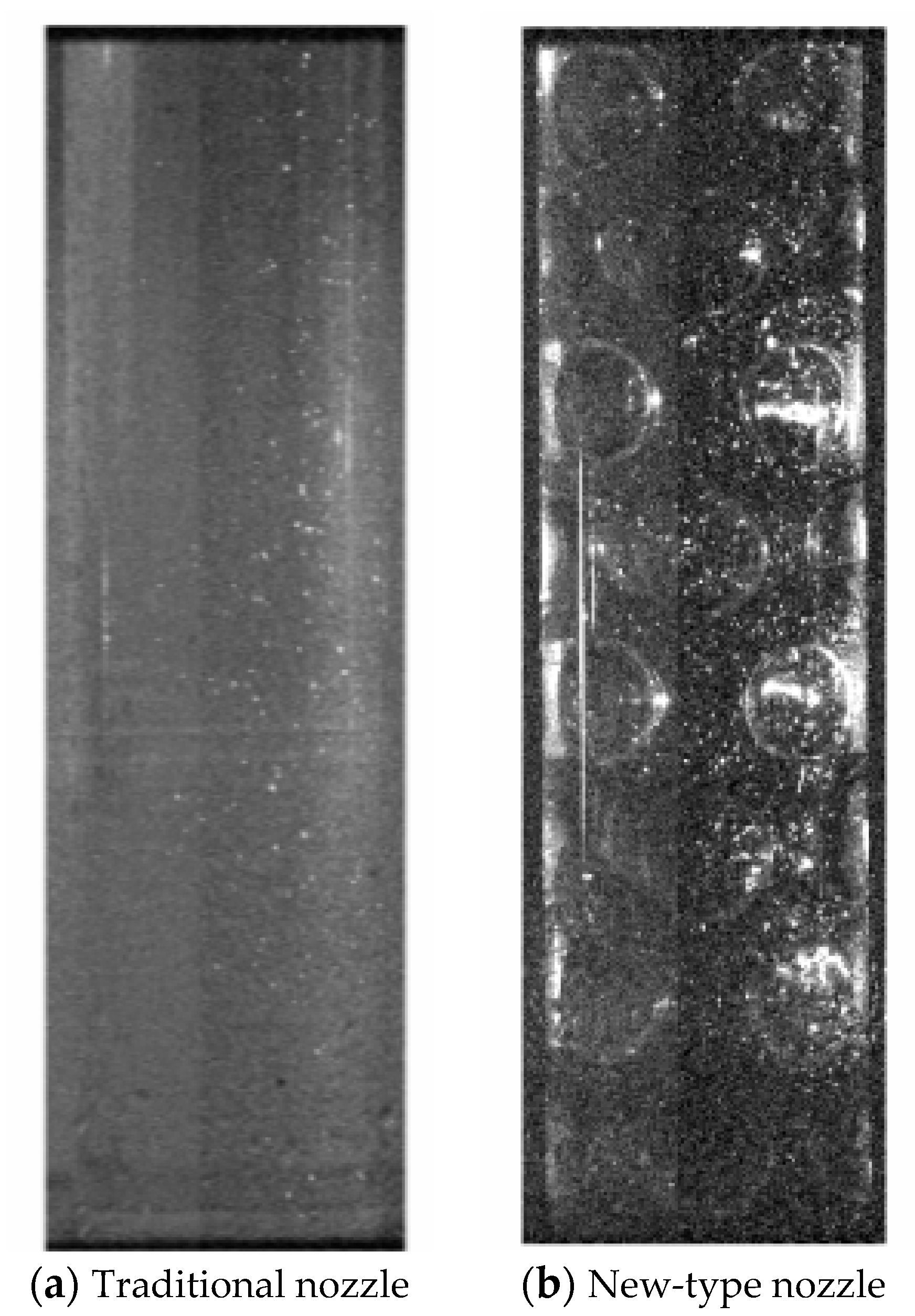
2.3. Experimental Results and Discussion

On the water model shown in Figure 1, separate physical experiments were performed on the two types of nozzles by using the PIV technique to capture and analyze the flow state within the nozzles. When the water levels in the tundish and in the mold reached the required heights, the water level in the tundish became relatively stable without swirl flow, and after keeping the water cycling stable for 10 min, tracer particles were added, and the flow state in the middle section of the nozzle was captured with the PIV. The captured images are shown in Figure 3.
The PIVview software (Version 3.0) is used to process the captured images and the results are shown in Figure 4. It can be seen from this figure that the flow field in the traditional nozzle, from top to bottom, exhibits a trend of relatively stable flow, and the flow state in the nozzle basically does not change; in the flow field inside the new-type nozzle, however, the water flows in collision with the hemispherical crown on the inner wall of the nozzle, resulting in lateral velocity components and thus reducing the longitudinal velocity component. In addition, the internal flow state of the new-type nozzle also produces an outflow that looks similar to a spiral flow.
Figure 5 shows the numerical simulation results of the flow fields in the same nozzles under the same operation conditions as those for Figure 4. A comparison between Figure 4 and Figure 5 indicates that the flow patterns shown by the physical model and numerical model are rather consistent. Using PIV to measure the water model experiment, it is found that in the interior of the submerged entry nozzle, the vertical velocity distribution law of the traditional nozzle is found, and the abnormal change is produced in the new-type nozzle, and the vertical vector is reduced. Due to the limitations of the experiment, the velocity of the cross-sectional area of the submerged entry nozzle cannot be collected. Therefore, a computational fluid dynamics (CFD) numerical simulation method is adopted to further investigate the details of the internal flow state both in the new-type nozzle and in the mold in comparison with those in the traditional nozzle and mold, which is described in the following sections.

3. Numerical Simulation Research

3.1. General Assumptions of the Numerical Model

The flow of molten steel in the nozzle and the mold is a complex turbulent continuous flow. In the present computational fluid dynamics numerical simulation work, the following general assumptions are made: (1) the flow of molten steel in the submerged entry nozzle and the mold is incompressible and steady state; (2) the operation parameters and physical properties of the molten steel are constant; (3) ignore heat transfer in the submerged entry nozzle and the mold; (4) ignore the influence of mold vibration on flow; (5) ignore the influence of the solidified shell on the flow in the mold; and (6) ignore chemical reactions in the submerged entry nozzle and the mold.

3.2. Governing Equations

(1) Continuity equation
( ρ u ) x + ( ρ v ) y + ( ρ w ) z = 0
where ρ is the fluid density, u, v, and w are the velocity components of the fluid in x, y, and z directions, respectively; and x, y, and z are Cartesian coordinate axes.
(2) Momentum equations
( ρ u u ) x + ( ρ u v ) y + ( ρ w u ) z = p x + x μ e f f u x + y μ e f f u y + z μ e f f u z
( ρ u v ) x + ( ρ v v ) y + ( ρ w v ) z = p y + x μ e f f v x + y μ e f f v y + z μ e f f v z
( ρ u w ) x + ( ρ v w ) y + ( ρ w w ) z = p z + x μ e f f w x + y μ e f f w y + z μ e f f w z ρ g
where g is the gravitational acceleration, and μeff is the effective viscosity coefficient.
(3) Standard k-epsilon turbulence equations [15]
k   equation :   ( ρ k U i ) X i = X j μ + μ t σ k k X j + μ t U i X j + U j X i U i X j ρ ε
epsilon   equation :   ( ε U i ) X i = X j μ + μ t σ ε ε X j + C 1 ε ε k μ t U i X j + U j X i U i X j C 2 ε ρ ε 2 k
where U is the velocity component in the Cartesian coordinate system; X the Cartesian coordinates; subscripts i and j the Cartesian coordinate indices (in x, y, and z directions), respectively; μt the turbulent viscosity; and c1ε, c2ε, σk, and σε the model constants, which are assigned with values of 1.44, 1.92, 1.0, and 1.3, respectively [15].

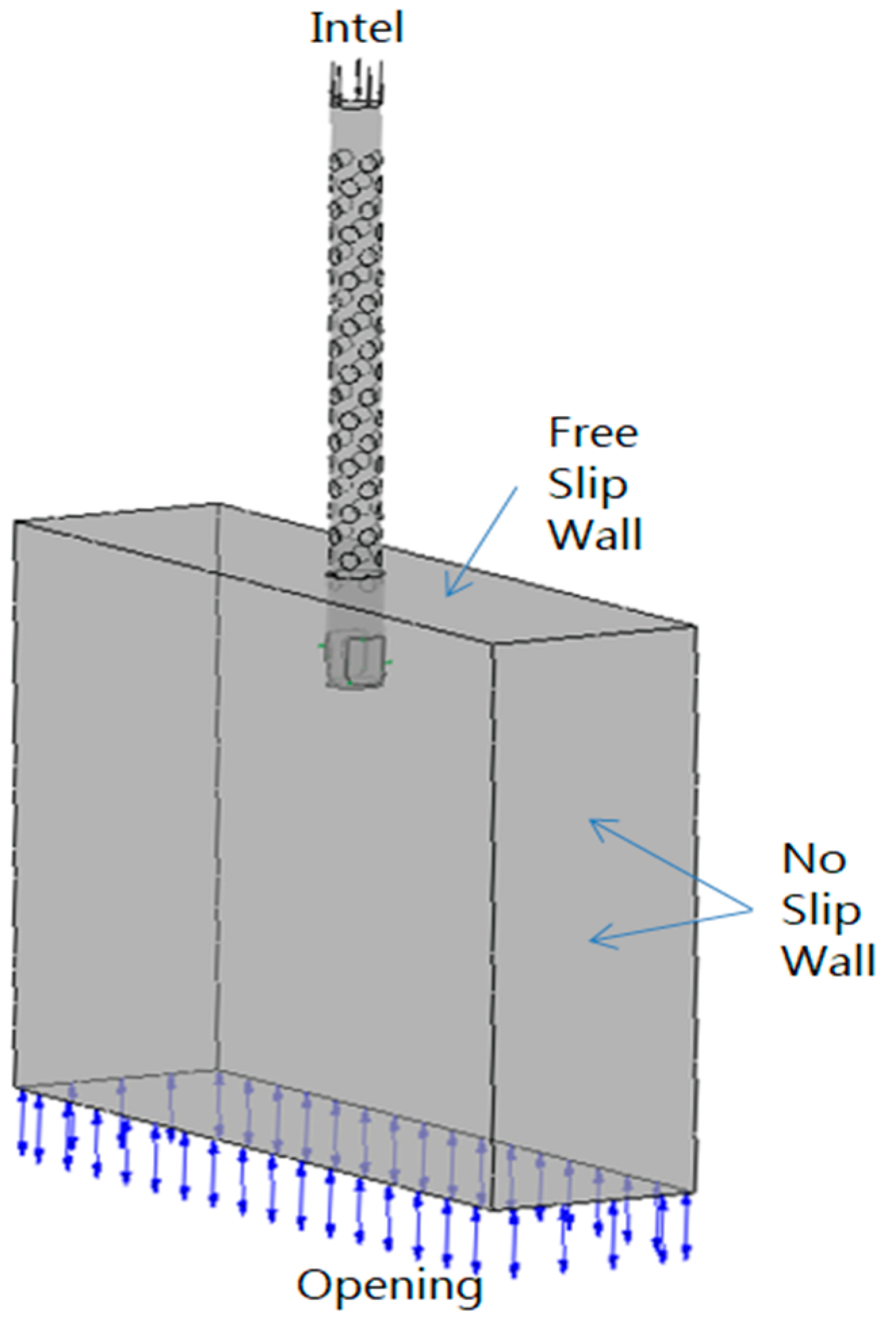
3.3. Boundary Conditions and Computation Initialization

Figure 6 is the computation domain and boundary conditions defined in the present work. The top inlet face of the submerged entry nozzle is defined as a flow inlet with a fixed normal velocity whose value is determined from the casting speed. In this numerical simulation study, the casting speed is set to 1.3 m/min. The bottom face of the mold is defined as a flow outlet over which the normal derivative of each physical quantity is set to zero. The upper liquid level is set as a free surface without considering the influence of mold flux. The walls of the submerged entry nozzle and the mold are set as non-slip solid faces.
We used a Hewlett-Packard (Palo Alto, CA, USA) computer with Intel Core i5-7500 @3.4 GHz (quad-core) to solve the above equations in the simulation calculation. It took about 1 week to complete the calculation. The initial velocity of the computation domain is set to 0 m/s, the initial relative pressure to 0 Pa, and the turbulence intensity to 5%. The physical properties of the simulated materials are shown in Table 1.

3.4. Numerical Simulation Results and Analysis

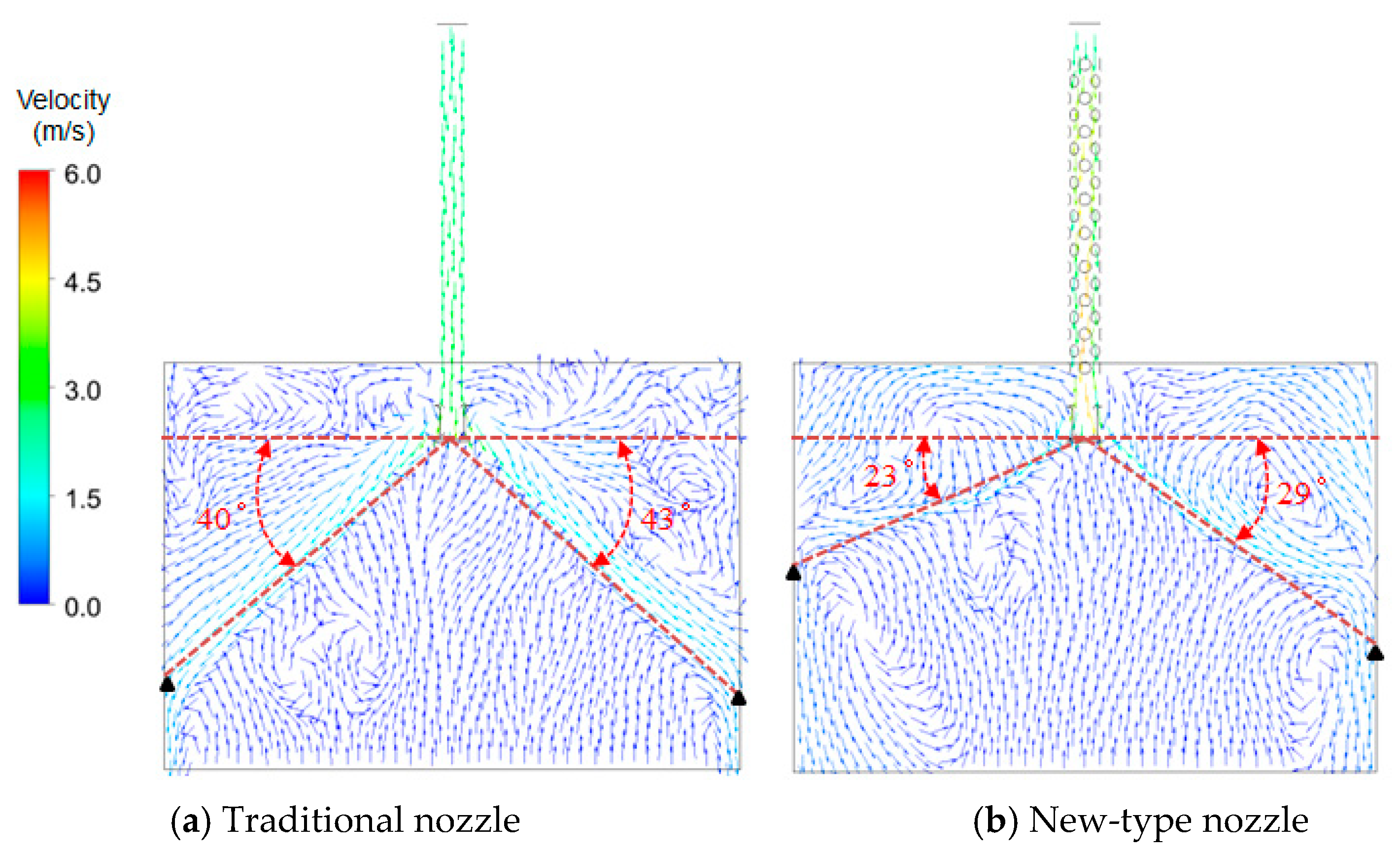
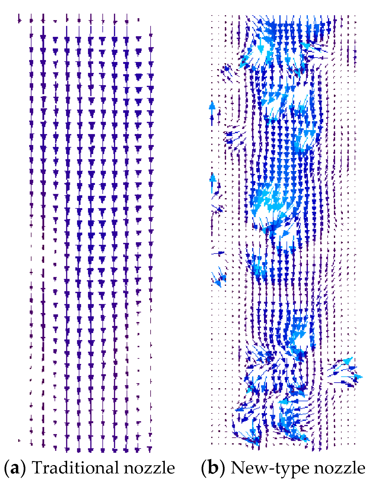
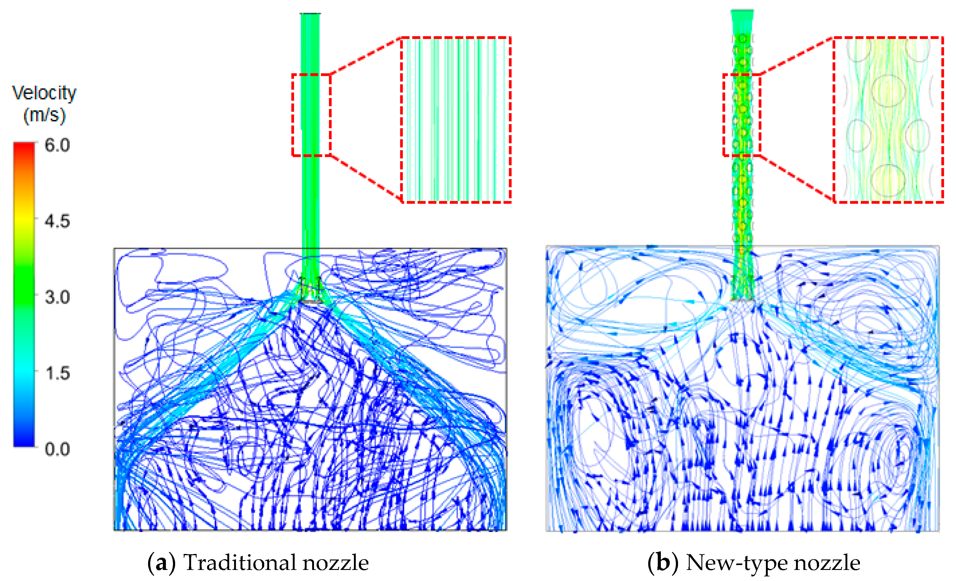
3.4.1. Influence of Nozzle Type on Flow Field

Figure 7 shows the numerical simulated streamline patterns on a wide-face symmetrical plane (x–z plane) in continuous casting mold with the traditional nozzle and new-type nozzle, respectively. It can be seen from this figure that inside the submerged nozzle, a discernible decrease in the trace of vertical downward flow is observed, alongside the occurrence of flow around within the nozzle. After the molten steel flowing out of the two outlets of the submerged entry nozzle, the flow field is divided into upper and lower return flow regions. The upper return flow region is mainly affected by the meniscus and the mold wall, whereas in the lower return flow region, a portion of the molten steel moves at a certain casting speed, and the other portion of the molten steel is in a circulating movement due to the formation of negative pressure underneath the two steel flow jets. In the mold at the lower part of the traditional nozzle, a higher impact strength leads to an increased presence of floccules within the mold, resulting in an irregular flow pattern. This irregular flow pattern poses a significant risk of slag entrapment, consequently leading to a deterioration in the quality of the produced steel billet. Compared with the traditional nozzle, the molten steel impact depth in the mold with the new-type nozzle is shallower and the return flow region position is significantly closer to the free surface molten steel, which would be advantageous to the floating removal of inclusions.
Figure 8 shows the numerically predicted x–z plane velocity vector distributions in the mold with different nozzles. As seen, the impact depth of the traditional nozzle is deep, which is between 52.53 and 54.67 cm, and the impact angle is between 40 and 43 degrees, the upper return flow region is too close to the meniscus, where fluctuations occur greatly. However, the impact depth of the new-type nozzle is shallow, which is between 26.5 and 33.61 cm, and the impact angle is between 23 and 29 degrees, and the upper return flow region is close to the lower return flow region, so the flow is stable and the stirring is even, which is conducive to the floating of inclusions.
Figure 9 shows the velocity vector distributions on different cross-sections of the two nozzles. The flow inside the traditional nozzle is gradually accelerated from top to bottom, and the steel ejects out of the nozzle outlets. From Figure 9a,c,e, it is evident that the flow within the traditional nozzle is vertically downward, with the highest velocity occurring at the center. It then evenly rushes out to both sides at the outlet due to the shape limitation (as shown in Figure 9g). However, inside the new-type nozzle, while the steel flows from top to bottom, the current collides with the hemispherical crowns, resulting in transverse velocity components, and produces a small vortex between adjacent spherical crowns. From Figure 9b, transverse velocity is observed. Although Figure 9d does not display a hemisphere crown on the inner wall, it still exhibits transverse velocity. The presence of regular swirling flow inside the nozzle is clearly visible in Figure 9f. As depicted in Figure 9h, the overall flow spirals downward and rotates out of the nozzle outlet.
Figure 10 shows the velocity vector distribution on a horizontal cross-section at the steel-free surface in the mold with different nozzles (The circles shown in the figure stand for cross section of the submerged entry nozzles). It can be seen from this figure that the mold steel surface in the mold with the traditional nozzle produces relatively violent fluctuations, which are prone to trap slag. However, owing to its slow outlet flow velocity and shallow impact depth, the new-type nozzle maintains the molten steel surface flowing smoothly and uniformly in the mold.

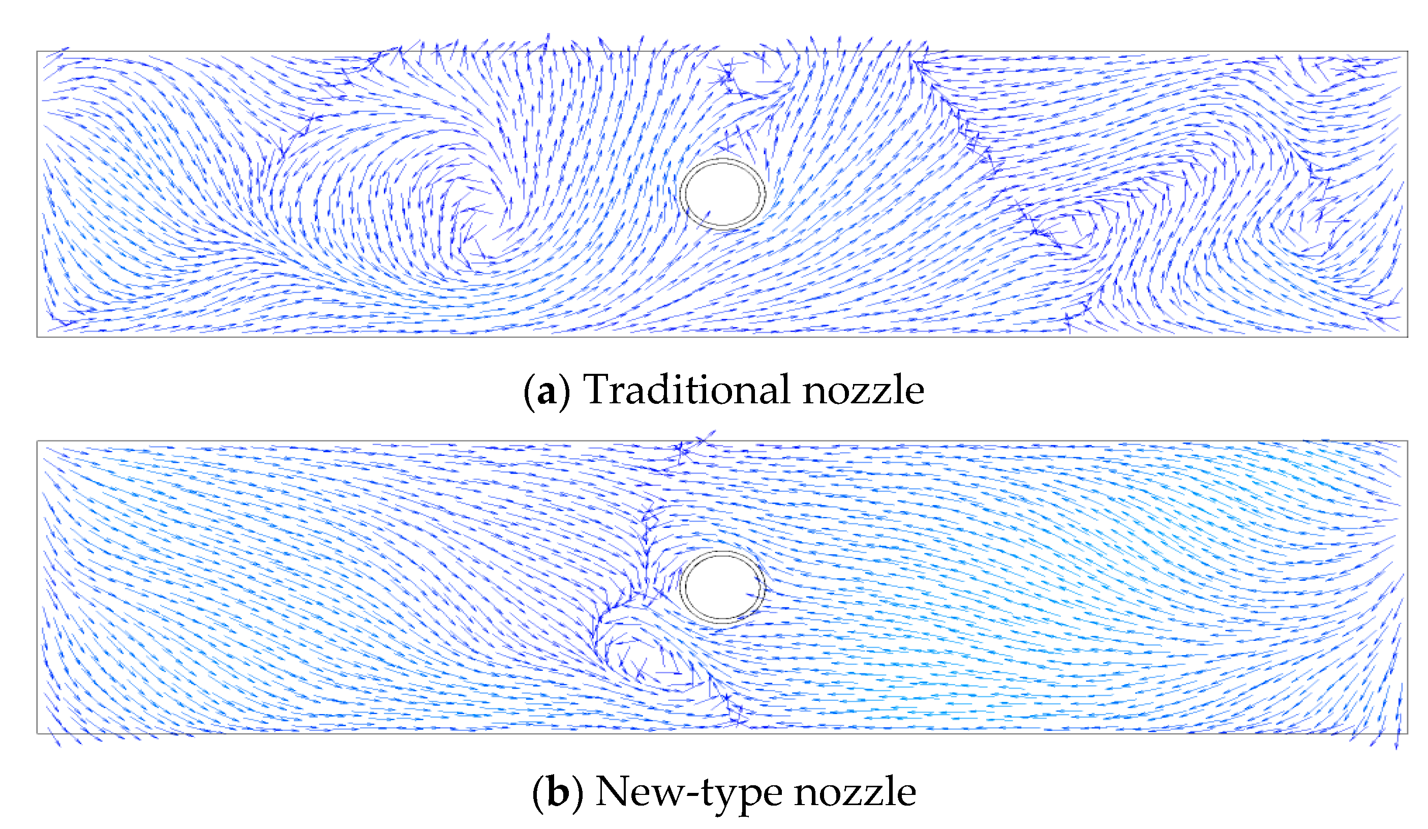
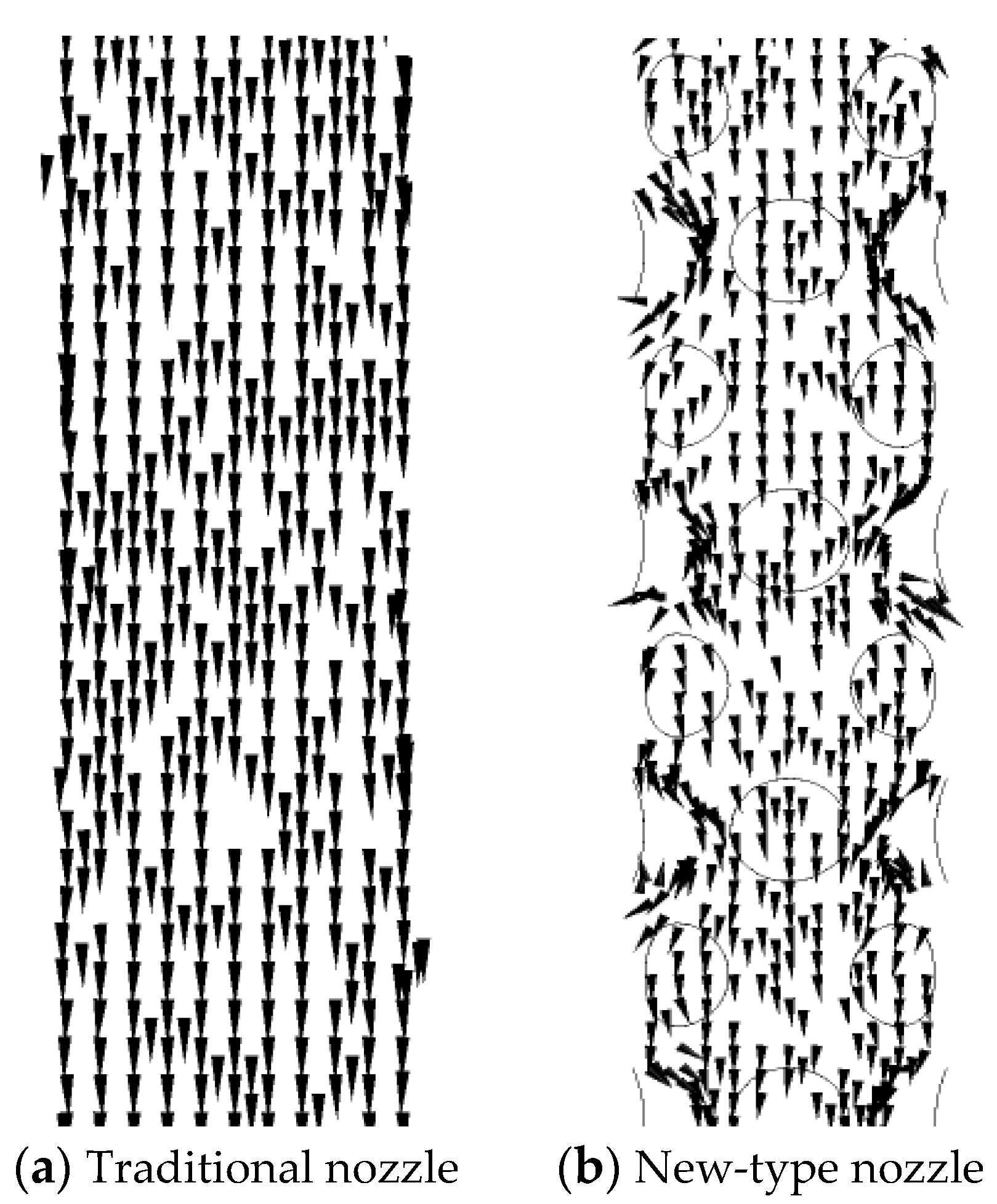
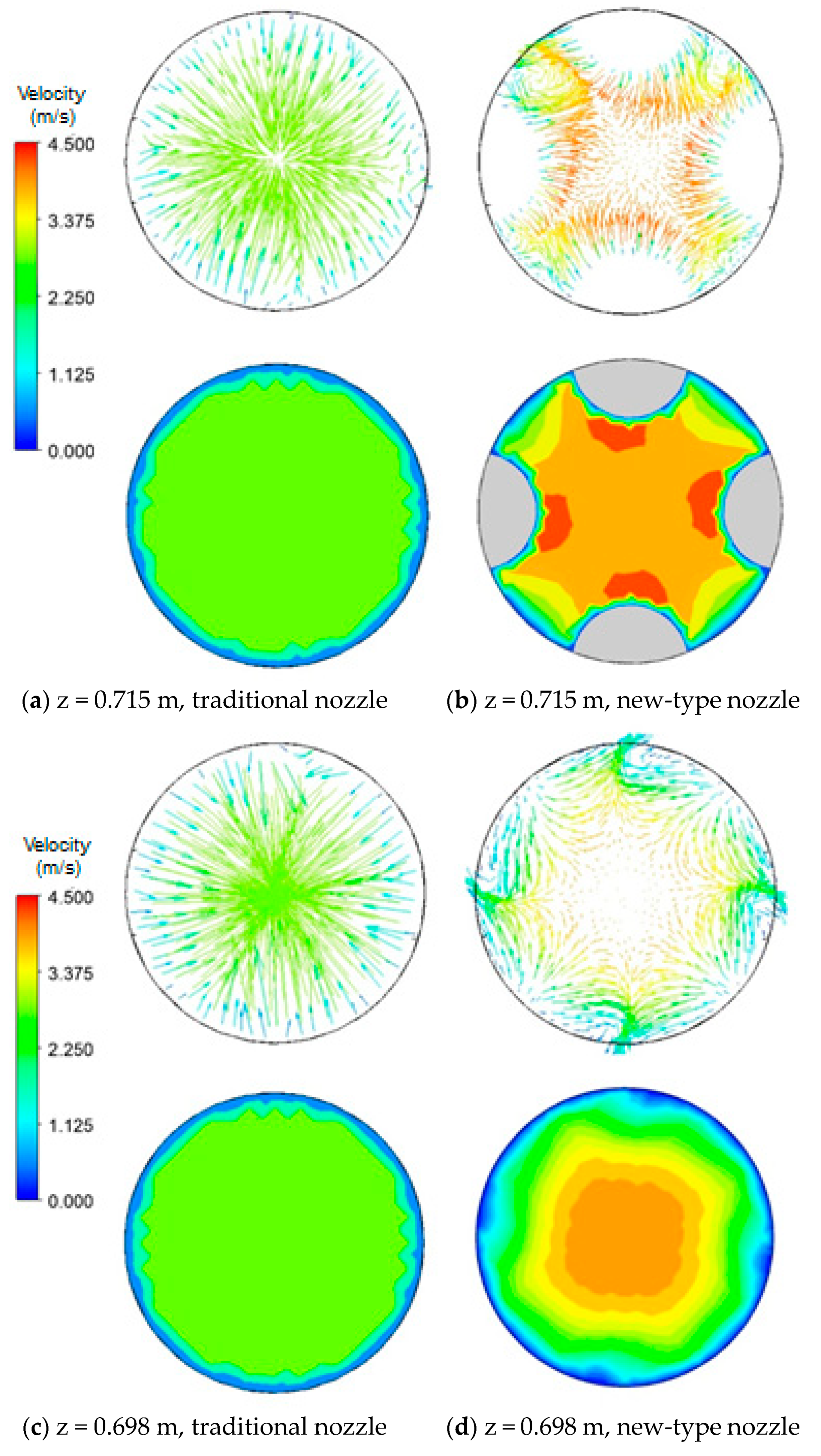
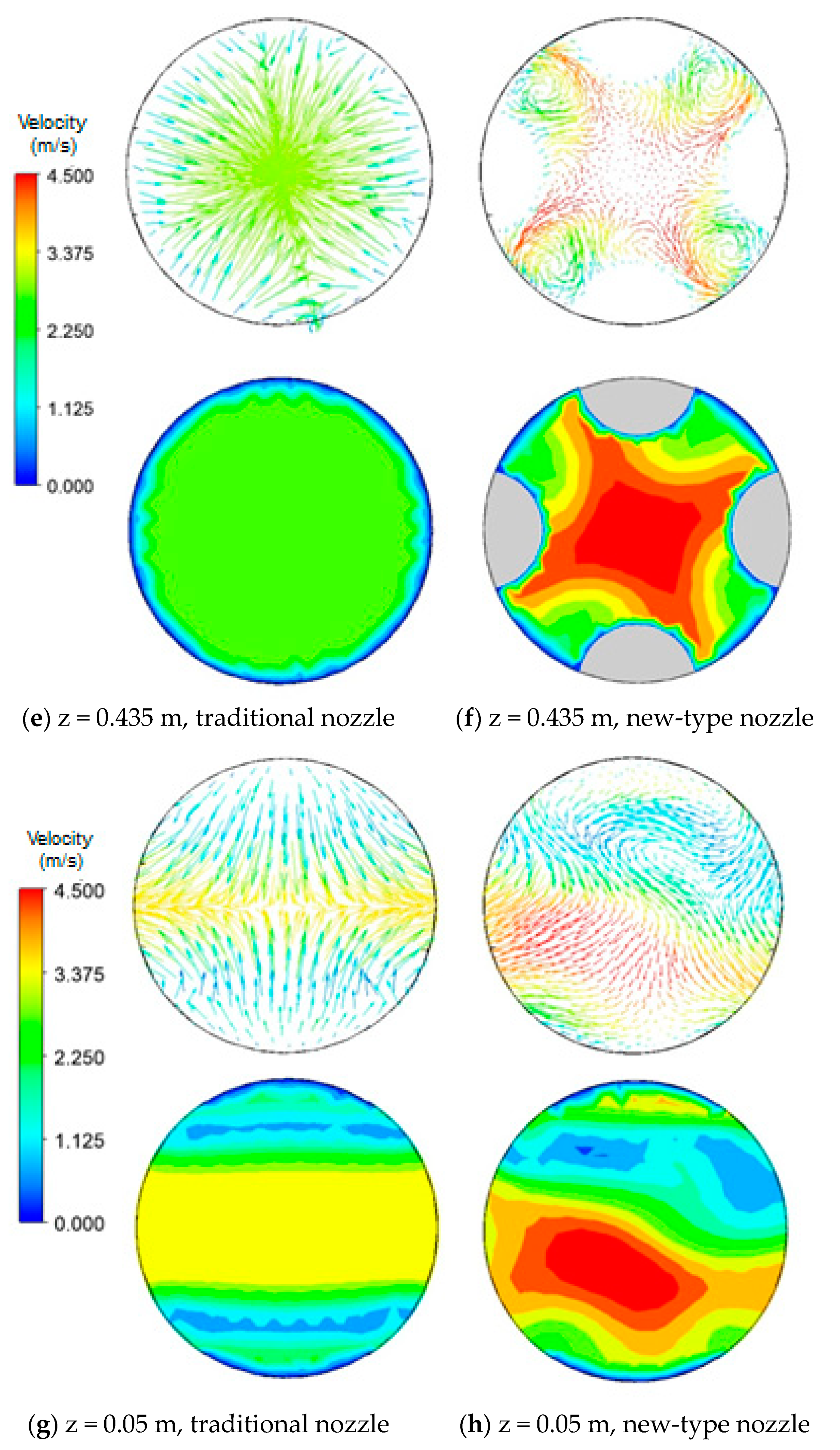
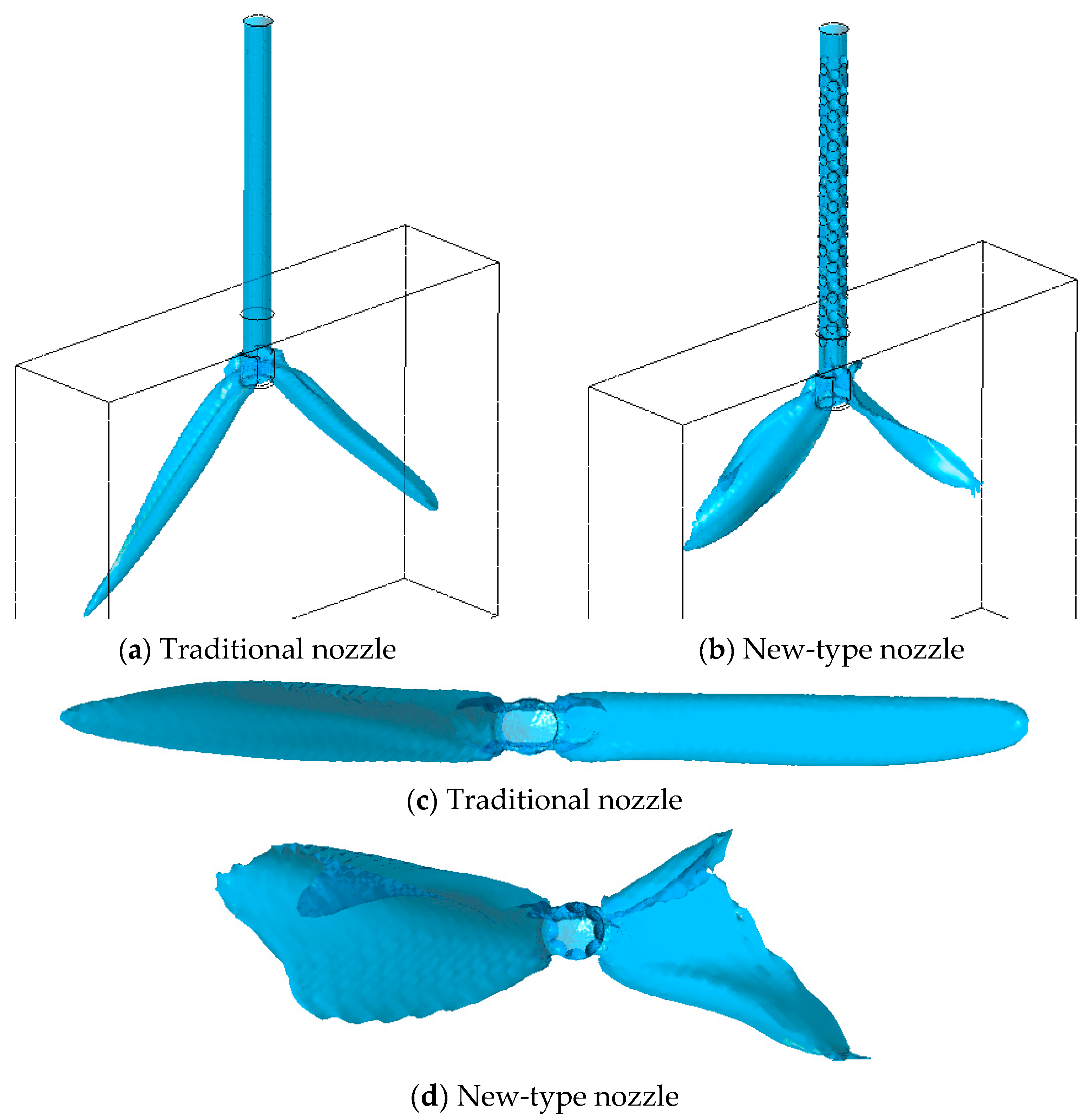
3.4.2. Effect of Nozzle Type on the Nozzle Outlet Jet

Figure 11 shows the flow jet state at the outlet of different nozzles. The traditional nozzle produces a single jet with a relatively concentrated flow. Due to the internal structure change of the new-type nozzle, horizontal velocity components are generated inside the nozzle, resulting in a vortex flow. Therefore, the molten steel flowing out of the nozzle outlets is in the form of rotating jets with dispersed flow streams. At the same flowing speed, the new-type nozzle jet impacts the mold wall with a shallow depth and its impact angle is small. The shape of the outlet jet is similar to a baseball glove, which reinforces the uniform diffusion of the steel liquid in the mold.

4. Conclusions

Through performing physical simulation experiments and computational fluid dynamics numerical simulations of steel flow inside different submerged entry nozzles and continuous casting mold, the following conclusions can be drawn:
(1)
Compared with the traditional nozzle, the new-type nozzle with internal hemispherical crowns has a shallower molten steel jet impact depth, the impact depth is between 26.5 and 33.61 cm, and the impact angle is between 23 and 29 degrees, and the position of the circuiting zone is closer to the molten steel free surface, which is more conducive to the floating of inclusions. The probability of occurrence of entrapment of top slag is small.
(2)
The longitudinal velocity distribution inside the traditional nozzle is uniform. Inside the new-type nozzle, however, transverse velocity components are generated due to the existence of the hemispherical crowns, forming swirl jets at the nozzle outlets with reduced velocity. Therefore, different from the traditional nozzle, the outlet flow from the new-type nozzle is a rotating jet with weaker impact, which is beneficial for using higher casting speed.

Author Contributions

Conceptualization, M.S.; Methodology, C.C. and Y.P.; Software, X.D.; Formal analysis, C.C.; Investigation, C.C.; Data curation, M.Z., X.D. and C.S.; Writing—original draft, C.C.; Writing—review & editing, M.S., Y.P. and C.S.; Supervision, M.S. and Y.P.; Project administration, M.Z. All authors have read and agreed to the published version of the manuscript.

Funding

This research was financially supported by the natural science fund program projects of the Department of Science & Technology of Liaoning Province (Project No.: 2022-BS-297), the basic scientific research fund projects of the Educational Department of Liaoning Province (Project No.: LJKZ0267), the basic scientific research fund projects of the Educational Department of Liaoning Province (Project No.: 2023J0925), Liaoning Institute of Science and Technology 2024 Student Innovation and Entrepreneurship Training Program (Project No.: 202411430010), and Liaoning Institute of Science and Technology doctoral research initiation fund project (Project No.: 2307B04).

Data Availability Statement

All the data are included in the present manuscript.

Conflicts of Interest

The authors declare no conflict of interest.

References

  1. González-Trejo, J.; Real-Ramírez, C.; Miranda-Tello, J.R.; Gabbasov, R.; Carvajal-Mariscal, I.; Sanchez-Silva, F.; Cervantes-De-La-Torre, F. Influence of the Submerged Entry Nozzle’s Bottom Well on the Characteristics of Its Exit Jets. Metals 2021, 11, 398. [Google Scholar] [CrossRef]
  2. Jin, Y.L.; Gong, Z.J.; Wang, B.; Zhao, J.W. Experimental study of PIV used in slab continuous casting mold flow field. Chin. J. Process Eng. 2009, 9, 193–196. [Google Scholar]
  3. Yokoya, S.; Westoff, R.; Asako, Y.; Hara, S.; Szekely, J. Numerical Study of Immersion Nozzle Outlet Flow Pattern with Swirling Flow in Continuous Casting. ISIJ Int. 1994, 34, 889–895. [Google Scholar] [CrossRef]
  4. Cai, C.Y.; Shen, M.G.; Ji, K.F.; Zhang, Z.S.; Liu, Y.J. Research on the Influence of the Inner Wall Structure of the Continuous Casting Submerged Nozzle on the Stream of Molten Steel. Trans. Indian Inst. Met. 2022, 75, 613–624. [Google Scholar] [CrossRef]
  5. Thomas, B.G. Continuous Casting. Mater. Eng. 2002, 19, 1075–8577. [Google Scholar]
  6. Xuan, M.; Chen, M. Optimal Design of the Submerged Entry Nozzle for Thin Slab Continuous Casting Molds. Metals 2021, 11, 1223. [Google Scholar] [CrossRef]
  7. Tsukamoto, N.; Ichikawa, K.; Iida, E.; Morita, A.; Inoue, J. Improvement of Submerged Nozzle Design Based on Water Model Examination of Tundish Slide Gate. In Proceedings of the 74th ISS Steelmaking Conference, Washington, DC, USA, 14–17 April 1991; Volume 74, pp. 803–808. [Google Scholar]
  8. Gao, W.F.; Shi, W.G. Research and application of tundish bottle nozzle in continuous casting. Steelmaking 1992, 8, 6–10. [Google Scholar]
  9. Tsukaguchi, Y.; Hayashi, H.; Kurimoto, H.; Yokoya, S.; Marukawa, K.; Tanaka, T. Development of Swirling-flow Submerged Entry Nozzles for Slab Casting. ISIJ Int. 2010, 50, 721–729. [Google Scholar] [CrossRef]
  10. Harada, T.; Tomoichi, T.; Shinichiro, Y. Design of Swirl Blade for Slab Casting: Development of Swirling Flow Immersion Nozzle for Slab Casting-2. CAMP-ISIJ 2002, 15, 164. [Google Scholar]
  11. Cui, X.C.; Wang, Y.H.; Ma, C.S. Numerical Simulation and Experimental study of Spin Stirring of molten Steel in Mold. J. Taiyuan Heavy Mach. Inst. 2002, 23, 221–225. [Google Scholar]
  12. Yang, Y.W.; Su, Z.J.; Chen, J.; Fan, W. Numerical simulation of fluid flow and temperature field of slab under composite magnetic field. J. Mater. Metall. 2021, 20, 185–191. [Google Scholar]
  13. Tong, Z.F.; Wang, F.P.; Qiao, J.L.; Luo, L.H. Continuous casting tundish nozzle clogging mechanism and preventive measures. Nonferrous Met. Sci. Eng. 2016, 7, 13–20. [Google Scholar]
  14. Li, D.; Su, Z.; Chen, J.; Wang, Q.; Yang, Y.; Nakajima, K.; Marukawa, K.; He, J. Effects of Electromagnetic Swirling Flow in Submerged Entry Nozzle on Square Billet Continuous Casting of Steel Process. ISIJ Int. 2013, 53, 1187–1194. [Google Scholar] [CrossRef]
  15. Launder, B.E.; Spalding, D.B. The numerical computation of turbulent flows. Comp. Meth. Appl. Mech. Eng. 1974, 3, 269–289. [Google Scholar] [CrossRef]
Figure 1. Schematic diagram of the water model experimental set-up. 1. Ladle, 2. tundish, 3. submerged entry nozzle, 4. mold, 5. rotameter, 6. PIV system, and 7. water reservoir.
Processes 11 03237 g001
Figure 2. Schematic diagram of nozzle structure.
Processes 11 03237 g002
Figure 3. Captured images of actual flow fields inside different submerged entry nozzles.
Processes 11 03237 g003
Figure 4. PIV visualized velocity vector fields inside different submerged entry nozzles.
Processes 11 03237 g004
Figure 5. Numerical simulation results of velocity vector fields inside different submerged entry nozzles. The circles shown in Figure 4b stand for the hemispherical crowns.
Processes 11 03237 g005
Figure 6. Computation domain and boundary conditions defined in the present work.
Processes 11 03237 g006
Figure 7. Streamline patterns on a wide-face symmetrical plane of continuous casting mold with different types of submerged entry nozzles.
Processes 11 03237 g007
Figure 8. Velocity vector distribution at x–z plane with different nozzles in mold.
Processes 11 03237 g008
Figure 9. Velocity vector distribution on different cross-sections of traditional and new-type nozzles (c.f., Figure 2 for z-level positions).
Processes 11 03237 g009aProcesses 11 03237 g009b
Figure 10. Velocity vector distributions at steel free surface level in continuous casting mold with different nozzles.
Processes 11 03237 g010
Figure 11. Flow state shape (iso-surface of velocity at 1 m/s) of jet at the outlet of different nozzles.
Processes 11 03237 g011
Table 1. Physical properties of molten steel and water.
Fluid MediaDensity (kg/m3)Dynamic Viscosity (kg/(m·s))Kinematic Viscosity (m2/s)
Molten steel70206.2 × 10−30.95 × 10⁻⁶
Water10001 × 10−31 × 10−6
Disclaimer/Publisher’s Note: The statements, opinions and data contained in all publications are solely those of the individual author(s) and contributor(s) and not of MDPI and/or the editor(s). MDPI and/or the editor(s) disclaim responsibility for any injury to people or property resulting from any ideas, methods, instructions or products referred to in the content.

