Article

New Developments in Detector and Bund Wall Standards to Mitigate the Risk of Hazardous Liquid Leaks

National Institute of Chemical Safety, Osongsaengmyeong 11-ro 270, Cheongju-si 28164, Republic of Korea
*
Author to whom correspondence should be addressed.
Processes 2023, 11(11), 3179; https://doi.org/10.3390/pr11113179
Submission received: 15 October 2023 / Revised: 1 November 2023 / Accepted: 4 November 2023 / Published: 7 November 2023
(This article belongs to the Special Issue Chemical Process Risk Assessment)

Abstract

:
Ensuring early leak detection and implementing effective secondary containment systems are critical for preventing the dispersion of hazardous liquids and minimizing the casualties of a chemical accident. This study reviews the standards for leak detectors and their placement in various regions, as well as the key parameters involved in bund design such as bund capacity, bund wall height, and separation distance from the bund wall. In this study, Computational Fluid Dynamics (CFD) simulations are conducted considering storage tanks with heights (H) of 1.75 m, 3.5 m, and 7.0 m. The detection times using a level transmitter (LT) and a leak sensor are compared at eight monitoring points. Exclusively employing the leak sensor led to a significant detection time delay of up to 16 times, ranging from 0.5 s to 8.1 s depending on the placement of the leak sensors. However, the average rate of liquid level change was 3.0 mm/s, which demonstrates that the LT consistently detects leaks faster than the leak sensor at all monitoring points. Hence, the integration of an LT alongside a leak detector offers a valuable approach to expedite leak detection, regardless of the direction or location of the leak. Furthermore, the optimized separation distance between the storage tank and the bund wall is suggested. The analytical solution and numerical solution for a separation distance matches up to 95% for H = 1.75 m. The separation distance increases as both the tank height and the height of the leak source increase. The relationship between the separation distance and the tank height exhibits a square root dependence on the liquid level from the leak point. The proposed detection method and optimized separation distance hold the potential to facilitate a revision of liquid storage and handling standards grounded in robust scientific and quantitative evidence.

Graphical Abstract

1. Introduction

The leakage of hazardous chemical liquids not only results in significant environmental harm, affecting soil and water bodies, but it also poses substantial risks to human health [1]. Furthermore, the potential for the spilled liquid to vaporize and ignite can lead to fires or explosions, causing severe catastrophic damage and endangering human lives [2]. An analysis of chemical accident statistics in South Korea over a span of nine years, from 2014 to 2022, reveals that 590 were leakage-type accidents out of a total of 743 chemical accidents, accounting for approximately 80% of all chemical accidents [3]. The two leading causes of these accidents were non-compliance with safety standards, contributing to 40% (300 cases), and facility defects, accounting for 38% (281 cases). Consequently, the prevention of chemical release accidents and the establishment of relevant safety standards have become increasingly vital and emphasized.
In particular, past incidents serve as reminders of the significance of timely leak detection and the implementation of proper containment systems for hazardous materials. For instance, in 2010, a coal gas leakage accident occurred at a Hebei iron and steel company, resulting in 21 fatalities due to the absence of gas detection equipment to promptly identify the leakage [4]. Similarly, on 21 July 1999, a significant incident involved the loss of approximately 12 tonnes of sodium cyanide solution into the environment, including the River Tees, due to inadequacies in the secondary containment system [5]. This incident prompted the upgrade of the containment system to prevent similar occurrences in the future. The above accidents highlight the critical importance of timely leak detection and the implementation of proper containment systems to mitigate the impact of chemical accidents.
In major accidents, poorly designed alarm systems have been identified as contributing factors [6], emphasizing the importance of effective early leakage detection to prevent harm to the environment and minimize product loss. For the early detection, the pressure fluctuation has been utilized for pipeline leaks [7] and machine learning has been applied for the leak of underground storage tanks [8]. In both the water and oil industries, the evolution of leak detection technology, including supervised learning algorithms [9] and acoustic emission methods [10], is progressing swiftly. Each detection method has its own advantages and disadvantages; thus, a combination of multiple leak detection systems is recommended to address these limitations [11]. A hybrid leak detection system combining thermal video and Fourier Transform Infrared spectrometer has been investigated for efficient gas leak localization [12]. Additionally, a wireless hybrid chemical sensor has been developed for the detection of volatile organic compounds [13]. The detection techniques in hybrid forms offer increased accuracy compared to standalone software-based methods, resulting in lower error rates and false alarm rates. Statistical analysis combined with Real-Time Transient Monitoring has been employed to reduce false alarms [14]. Moreover, alternative techniques such as ground-penetrating radar, temperature profiling, and photoacoustic sensing have recently emerged as viable options [15]. However, most countries recommend the prompt leak detection but there is no specific regulations on placement of detector for early detection as shown in Figure 1. One advantageous solution for early leak detection is the use of a level transmitter (LT), which can detect leaks irrespective of their location or direction. However, LT devices are sensitive to temperature and relative humidity of the handled materials [16]. In cases involving high-temperature and high-pressure containers, differential-pressure-type level transmitters are preferred over electrode-type or displacement-detection-type level transmitters [17]. Combining LT with leak detection sensors can significantly contribute to timely detection of chemical accidents. Hence, there is a need for research to ascertain the feasibility of incorporating a level transmitter into the safety standard.
Regarding a secondary containment, it serves as a control measure to prevent the release of hazardous contents [18]. Various forms of secondary containment systems exist, such as bunds, drip trays, off-gas treatment systems (e.g., scrubbers and flares), sumps, double-skinned tanks, expansion vessels, and concentric pipes [19]. To enhance safety, investigations have been conducted on the design requirements of secondary containment systems for pressurized heavy water reactors [20], as well as the construction materials for coatings used in secondary containment systems [21]. Bund wall design standards for secondary containment systems vary across different countries, often lacking scientific or quantitative reasoning. The recommended range for bund wall height is typically defined as a minimum of 0.5 m to a maximum of 1.8 m [22,23,24], while the separation distance requirements between the storage tank and bund wall depend on the volume, radius, and height of the storage tank [25,26,27]. Furthermore, the need for appropriate separation distance is crucial to prevent spillage on roads, pathways, and work areas around storage tanks containing toxic chemicals [28]. Therefore, it is imperative to develop standardized and universally applicable criteria for separation distance based on scientific evidence. In the realm of bund wall systems, the effectiveness of containing storage tank leaks hinges on critical design factors, encompassing shape, slope, and embankment features, including the incorporation of breakwater structures [29]. Additionally, a comprehensive investigation has probed the impact of bund wall configurations on wind patterns, overtopping rates, and the dispersion of substances, such as LNG [30]. Nevertheless, research on the optimal bund wall configuration and detector placement, particularly concerning the management of hazardous substances like sulfuric acid, remains scarce. Notably, specific numerical guidelines for designing efficient barrier systems are conspicuously absent, even in China [31].
In this study, the standards of detection systems and bund walls are reviewed and the appropriate standards, including the optimal separation distance, are suggested. The analytical results are subsequently validated through Computational Fluid Dynamics (CFD) simulation results. Furthermore, the study investigates the variation in detection time based on detector location and examines the potential application of a level transmitter as a complementary detection method. These insights can be leveraged to improve the design and operation of storage tanks and to develop more efficient strategies for leak detection and prevention. For instance, incorporating level transmitters with leak detectors and determining the optimal separation distance between the bund wall and storage tank are potential approaches to enhance safety and minimize environmental risks.

2. Review of Mitigation Measures Standards

The early detection of leaks through strategically placed detectors and secondary containment systems restricting the spread of hazardous chemicals are crucial to minimize the damage caused by chemical accidents and prevent catastrophic events.

2.1. Review of Leak Detector Standards

The purpose of the installation of a leak detector is to provide early warning for leaks from facilities to allow for quick action to protect the environment and human health. In the realm of risk management processes, scholarly research on leak detection has historically placed a greater emphasis on subterranean pipelines [8] and offshore pipelines [14] when compared to their above-ground counterparts. This inclination is often attributed to the inherent complexities associated with visually identifying above-ground leaks. The effectiveness of early warning systems utilizing Leak Detection Systems (LDSs) is impeded by several challenges, such as limitations imposed by current detection devices [32], the intricacy of predicting leak locations and optimizing detector placement [33], and the necessity to minimize the number of deployed detectors for cost efficiency [34]. To ensure regulatory compliance, our study initially examines the minimum requirements stipulated by law and subsequently reviews the relevant literature to determine the legally acceptable range of options for the level transmitter as a leak detection system. Through CFD simulations, we explore methods to improve leak detection speed by comparing the detection time of level transmitters and point-type detectors.

2.1.1. Level Transmitter as a Leak Detect System

The sole reliance on leak detectors makes it challenging to achieve the early detection of leaks. Moreover, the installation of leak detectors around the entire storage tank is impractical considering economic and maintenance considerations. However, when combined with level transmitters, it can become a feasible solution. Significant advancements have been made in the development of level transmitters, particularly with laser level gauges that provide unparalleled precision [35].
Extensively the device for measuring the contents of the tank can be considered as one of the ‘leak prevention technologies’ [36] or an ‘acceptable detection method’ [37] and the level transmitters can generally be considered as an ‘appropriate application of detection methodology’ [36]. The Risk Management Plan (RMP) of the Environmental Protection Agency (EPA) specifies ‘acceptable detection methods’, which include monitoring and control instrumentation with alarms, as well as detection hardware such as hydrocarbon sensors [36].
Nevertheless, it is worth noting that the deployment of a level transmitter is contingent upon adhering to the specific conditions as stipulated by the U.S. EPA. These conditions entail the incorporation of monitoring and control instrumentation, as well as the implementation of detection hardware, such as hydrocarbon sensors [36], which play an integral role in ensuring safe and efficient operations. Moreover, the state of Victoria in Australia mandates the installation of both a level transmitter and level switch, with the latter needing to meet the stringent conditions outlined in the criterion, which emphasizes the installation of critical alarms that can automatically disengage the supply to the tank in case of any hazardous incidents [38].
In the Victorian government’s guidelines for liquid chemical storage tanks, there is no direct mention of the use of level transmitters as part of the detection system. However, the electrical device section of the guidelines does include provisions for installing level transmitters into liquid chemical tanks for instrumentation and to prevent chemical leakage. The guidelines also allow for the installation of level switches with critical alarms that can automatically cut off the supply to the tank [38].
In South Korea, the number of leak detectors required in chemical facilities is determined by their distance from each other, as stipulated by the Chemical Substance Management Act [22]. Therefore, level transmitters cannot replace the detectors themselves; however, they may be utilized as supplementary measures to enhance the efficacy of the leak detection system.
The integration of alarm-equipped level transmitters emerges as a robust and compliant approach for monitoring instrumentation in liquid chemical storage tanks, aligning with regulatory requirements such as RMP regulations. Incorporating these advanced devices seamlessly into safety protocols enables operators to enhance safety measures effectively and ensure regulatory compliance. The alarm capability of level transmitters facilitates prompt identification of potential releases, enabling the swift implementation of necessary safety measures to prevent accidents and mitigate their consequences. This strategic integration contributes to a comprehensive safety strategy and empowers early detection of leaks, significantly reducing the risk of chemical spills and enhancing overall safety in storage facilities. Such proactive measures serve as invaluable tools for safeguarding personnel, assets, and the environment, fostering a secure operational environment within the process industries.

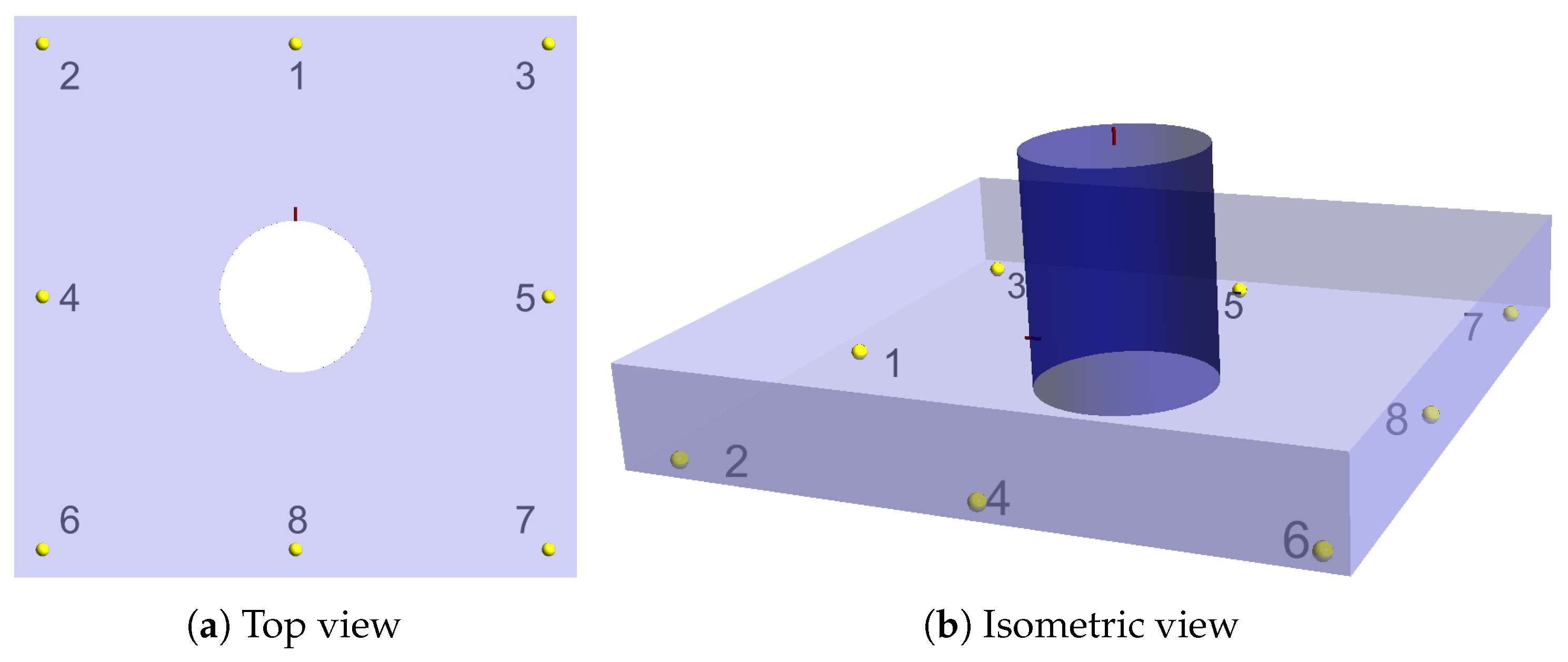
2.1.2. Detector Location

Locating the leak detector at an optimized location can be challenging, resulting in variations in detection time depending on the detector’s position and the leak point [39]. To address this issue, the level transmitter should be taken into account, as it is not dependent on the location of the leak point.
The national standards and regulations on the placement of leak detectors vary with the region. Most countries have separate standards or guidelines for different types of liquids and gases, such as petroleum or volatile organic compounds, as well as for underground storage tanks [40]. However, there are no specific regulations regarding leak detection systems that can be universally applied to all liquid aboveground storage tanks.
In the United States, there is no specific regulation regarding the location of detectors for the prevention of chemical accidents for hazardous chemicals. However, the RMP of the EPA addresses that the detector must be located in the containment area and the secondary containment system must have the capability to detect a discharge from the tank within 24 h or at the earliest reactive time [41].
In Australia, the location of detectors for hazardous chemicals may depend on several factors, such as tank size and configuration, the nature of the stored chemical, and the sensitivity of the surrounding environment. The general recommendations for detector placement include installing them at the lowest point of the containment system for prompt leak detection, selecting easily accessible locations for maintenance and inspection purposes, situating detectors in areas prone to potential leaks, and prioritizing areas that could pose risks to the environment or human health [42].
In South Korea, strict regulations [22,43] are enforced for all hazardous chemicals. The installation of one or more detectors on or within the secondary containment bund is required. The applicable regulations stipulate that for each floor circumference (10 m indoor, 20 m outdoor) of the hazardous chemical facility group, a minimum of one detector must be installed [22]. However, the number and placement of detectors may vary based on the size and configuration of the tank, the properties of the stored product, and the proximity of the tank to sensitive areas. It is important to consider these factors when determining the appropriate number and location of detectors for each situation.
Overall, our study emphasizes the importance of implementing comprehensive and standardized regulations for leak detection across international boundaries. Furthermore, it underscores the significance of employing efficient and tailored leak-detection systems and strategies that are suitable for various storage tank configurations and hazardous substances.

2.2. Review of Bund Design Standards

The purpose of installing bunds is to restrict the spread of hazardous liquids and minimize evaporation rates through the reduction of the liquid’s surface area [44]. When designing a bund, the primary considerations include bund capacity, bund wall height, and the distance between the storage tank and the bund wall. In the United States, the Occupational Safety and Health Act (OSHA) was enacted in 1970, and the National Fire Protection Association (NFPA) was formally established in 1996. In the United Kingdom, the Health and Safety at Work Act was introduced in 1974, while in Australia, OSHA received approval in 1983. These nations have a rich history of safety-related legislation, serving as influential role models for the formulation of safety regulations in other countries [45]. Table 1 summarizes the various standards for these key design parameters.

2.2.1. Bund Capacity

Bund capacity is a critical factor in containing potential leakage from storage tanks. Most standards assume that leaks will occur in a single tank at a time. Therefore, general requirements in the Health and Safety Guidance (HSG), the NFPA, and the Chemical Substances Control Act (CSCA) call for a bund volume with a capacity of 110% of the largest tank [23,27,46], although specific dimensions are not typically specified [47]. In Australia, the minimum bund capacity is defined as 100% of the largest container, with an additional 10% being recommended. However, in the case of multiple tank leakages, required capacity is related to the total volume of vessels within the tank farm. Australian standards [48,49], for instance, require a minimum bund capacity of at least 25% of the total volume of all vessels to mitigate the risks of chemical accidents. New Zealand and Ireland define both of the minimum bund capacity of 110% of the largest storage tank and 25% of the total volume of substance.
Table 1. Summary of bund design standards.
Regional StandardMinimum CapacityBund Wall HeightSeparation Distance
National Fire Protection
Association & Environmental
Protection Agency, US
110% of the largest tank [23]Maximum
1.8 m
(6 feet) [23]
0.9 m (3 feet)
from a secondary
containment system [25]
Health and Safety
Guidance, UK
110% of the largest container [46]Maximum
1.5 m (5 feet) [24]
Minimum 1 m for up to 100  m 3
2 m for above 100 m 3 [26]
Victoria, Australian
Standard [48]
100% of the largest container
25% of total volume of all
containers
N/AHalf height rule—half the
height of the tanks
Tasmania, Australian
Standard [49]
100% of the largest tank
25% of total volume of all
vessels
0.5∼1.5 mMinimum 1 m
Chemical Substances
Control Act,
South Korea [27]
110% of the largest tankAbove 0.5 m [22]1.5 m
1 3 of R when H < 15 m
1 2 of R when H ≥ 15 m
Health and Safety at Work Act,
New Zealand [50]
110% of the largest container
25% of total volume of all
containers
N/A H h b
IPC Guidance, Ireland [51]110% of the largest container
25% of total volume of all
containers
Maximum 1.5 mSufficient distance

2.2.2. Bund Wall Height

Table 1 lists several standards that recommend a minimum or maximum height for bund walls. According to the Australian Standard, storage tank bunds should be between 0.5 and 1.5 m in height, depending on their containment capacity [49]. The distance between the wall and the tank also affects the suggested height, with closer walls requiring greater height. The HSG does not specify a minimum height for bund walls, but it notes that low walls (1∼1.5 m) are commonly used despite their inadequate protection against catastrophic tank failure [19], as the degree of overtopping is proportional to the height of the tank [52]. The NFPA code [23] and HSG [24] establish different maximum heights for bund walls, with NFPA specifying 6 feet and HSG specifying 5 feet. In Ireland, there is a regulation that the maximum bund wall height should not exceed 1.5 m to facilitate safe egress from a bunded area during accidents and to prevent any obstruction to firefighting operations [51]. In accordance with the CSCA in South Korea, a minimum recommended bund wall height of 0.5 m is specified [22].
In addition, Clark et al. [44] proposed minimum bund wall heights for circular and rectangular bunds based on the requirement for over 100% containment ( b u n d t a n k ) and given by,
For a circular bund , h b R 2 H ( R + L s ) 2
For a rectangular bund , h b π R 2 H ( x y )
where b u n d and t a n k are the volume of bund and storage tank, respectively, h b is the height of bund wall, R is the radius of the tank, H is the height of a storage tank, L s is the separation distance between the tank and bund wall, and x and y are the dimensional length of bund including L s .
For a square-shaped bund ( x = y = 2 ( R + L s ) ), the minimum height of a rectangular bund can be less than that of a circular bund, i.e., ( h b ) circular > ( h b ) rectangular .

2.2.3. Separation Distance

The separation distance between the storage tank and bund wall is critical to avoid high pressure or damage to the wall and to prevent overtopping [53]. However, ensuring sufficient separation distance alone is not always adequate to prevent overtopping, as other factors such as the height and shape of the bund, and the addition of a deflector also play a significant role [29]. In this study, we define the separation distance as the minimum distance required for the fluid to reach the ground without directly impacting the bund wall.
Megdiche [54] conducted a CFD study to investigate the effect of separation distance on dynamic pressure ( P d = 1 2 ρ U 2 ). The results showed that dynamic pressure increases with decreasing separation distance due to the higher fluid velocity over a shorter travel distance. The HSE [55] specifies that bund walls must be capable of resisting the hydrostatic pressure exerted by the stored liquids and resist corrosion from the chemicals. From Equations (1) and (2), the bund wall height, h b , is inversely proportional to the square of separation distance, L s 2 , for the same bund capacity. The hydrostatic pressure ( P h = ρ g h ) exerted on the bund wall, in turn, is proportional to the height of the wall which may decrease as the separation distance increases. Hence, an increase in separation distance can lead to a reduction in hydrostatic pressure.
The minimum separation distance (hereafter denoted as L m i n ) with respect to tank capacity and height is regulated by the HSG and CSCA, respectively. As presented in Table 1, the HSG specifies L m i n of 1 m for tanks with a capacity up to 100 m 3 and 2 m for tanks with a capacity above 100 m 3 . In contrast, the CSCA allows for different options for L m i n depending on the tank diameter and height, including 1.5 m, one-third of tank height if the tank diameter is less than 15 m, and half of the tank height if the tank diameter is greater than 15 m. The EPA requires L m i n of 0.9 m (3 feet) between a storage tank and a secondary containment system [25]. The Australian Standard has different regulations for each region, and in Tasmania, L m i n is specified as 1 m regardless of tank capacity or height [49]. According to the half-height rule [48] in the Victoria region, the tanks should be separated from the bund edge by a distance of half the height of the tanks to prevent spills or leaks from reaching the surrounding environment. The New Zealand standard specifies the separation distance by taking into account the tank height, calculated as the difference between the tank height and the bund height [50].
Now, an analytical solution for the separation distance is obtained to examine its general applicability in the chemical industry. By applying the conservation of energy equation for inviscid and incompressible flow between the two locations [56], the top of fluid level and the exit of storage tank, the velocity of a leak can be obtained.
z 1 + P 1 ρ g + V 1 2 2 g = z 2 + P 2 ρ g + V 2 2 2 g + h f
z 1 = z 2 + V 2 2 2 g + f L D V 2 2 g
V e x i t = 2 g h 2 1 + f L D
where h f is the head loss due to friction that equals f L D V 2 2 g , f is the Darcy–Weisbach friction factor, L is the length of a pipe, D is the diameter of a pipe, and h 2 is the liquid level from the leak point which equals z 1 z 2 as shown in Figure 2.
Assuming constant acceleration motion, the fall time to the ground denoted by t, can be expressed as 2 h 1 g , where h 1 is the height of the leak point and g is the acceleration due to gravity. The separation distance between the storage tank and bund wall is ultimately determined by the height of the storage tank and leak point and given by
L s = V e x i t × t = 2 h 1 h 2 1 + f L D = 2 h 1 2 + H h 1 1 + f L D
where H is the total height of the tank and equals to h 1 + h 2 and the theoretical height of storage tank, H t can be designed using the theoretical height equation that relates to the capacity and height–diameter ratio of the tank [57], given by
H t = C a × r H / D 2 0.7857 3
where H t ( m ) is the theoretical height, C a ( m 3 ) is the designed tank capacity, and r H / D is the height–diameter ratio, which falls within the range of 0.5 to 1.5 [58].
By taking the derivative of Equation (6) with respect to h 1 , the maximum separation distance L m a x can be found to be equal to the total height of the storage tank, H, when the heights of the leak point and storage tank are both equal to half of the total height, i.e., h 1 = h 2 = H 2 .

3. Numerical Analysis of Standards on Mitigation Measures

3.1. CFD Modelling

The simulation of liquid leak from the flange of the storage tank is conducted using ANSYS FLUENT software, version 2021R2. The simulations employ the Reynolds-averaged Navier–Stokes equations with a realizable k ε turbulence model, considering two governing equations: continuity and momentum. The temperature effect is neglected, and hence the energy equation is discarded from the simulations. The governing equations for conservation of mass and momentum can be written as follows [59]:
ρ t + x i ( ρ u i ) = 0
t ( ρ u i ) + x j ( ρ u i u j ) = p x i + x j μ u i x j ρ u i u j ¯
where ρ is the density, u i is the mean velocity which components are ( u , v , w ) in x, y and z-direction, and ρ u i u j ¯ is the Reynolds stress which can be obtained from the following transport equations for the realizable k ε model [60].
The simulation considers the mixing of two materials, air and sulfuric acid, within the computational domain. The volume of fluid model is employed, with air selected as the primary phase and sulfuric acid chosen as the secondary phase. The densities of the two phases are 1.225 kg / m 3 and 1840 kg / m 3 , respectively. The pressure-outlet boundary condition is applied to the leak point and vent valve at the top of the storage tank, while the remaining boundary conditions are defined as walls. In order to enhance solution accuracy, the FLUENT software employs the SIMPLE pressure correction method for convergence and the second-order upwind scheme for momentum calculations [60]. To achieve improved convergence in the simulation results, the adaptive time stepping method is adopted, with minimum and maximum time steps set at 0.005 s and 0.1 s, respectively.

3.2. Geometry and Mesh

In this study, simulations of three different cases are performed according to the various storage tanks’ heights (H), which are 1.75 m, 3.5 m, and 7.0 m, as presented in Table 2. The storage tank has a diameter ( D t a n k ) of 2.7 m, and a leak diameter of 50 mm. As illustrated in Figure 3a, the initial state of the storage tank involves the presence of sulfuric acid, which is released when the valve or flange becomes damaged. The storage tank’s top is designed with an open vent to facilitate the entrance of air into the storage tank. Similarly, the outlet of the storage tank is designed to be open, allowing the sulfuric acid to discharge from the tank under the influence of potential energy and pressure forces. The exit velocity at the leak point is primarily determined from the Equation (5) due to the liquid level inside the tank.
Figure 3b demonstrates the dense grid arrangement for the sulfuric acid outlet and air vent inlet of case 2, with the addition of prism mesh along the walls. The number of mesh elements allocated for case 1, case 2, and case 3 are 3,809,175, 7,298,610, and 8,283,985, respectively, as outlined in Table 2.
For the comparison of detection time, the eight monitoring points (hereafter denoted as MP) which can be considered as detection points are positioned 5 mm above the ground and 50 mm away from the bund wall, at 45 degree angles from each other as shown in Figure 4. A grid sensitivity analysis has been performed by using three different grid resolutions, namely coarse, medium, and fine grids, which correspond to 4,280,161, 5,563,977, and 7,298,610 number of mesh elements for case 2, respectively. To achieve enhanced computational accuracy, the fine grid has been consistently chosen for all simulation cases, as it demonstrated an average variation of 4% in the volume fraction of H 2 SO 4 at the eight monitoring points when compared to the medium grid. Additionally, the number of mesh elements has been validated by assessing the convergence of results. The residuals of k, ε , velocities, and the volume fraction of H 2 SO 4 converged under 10 5 .

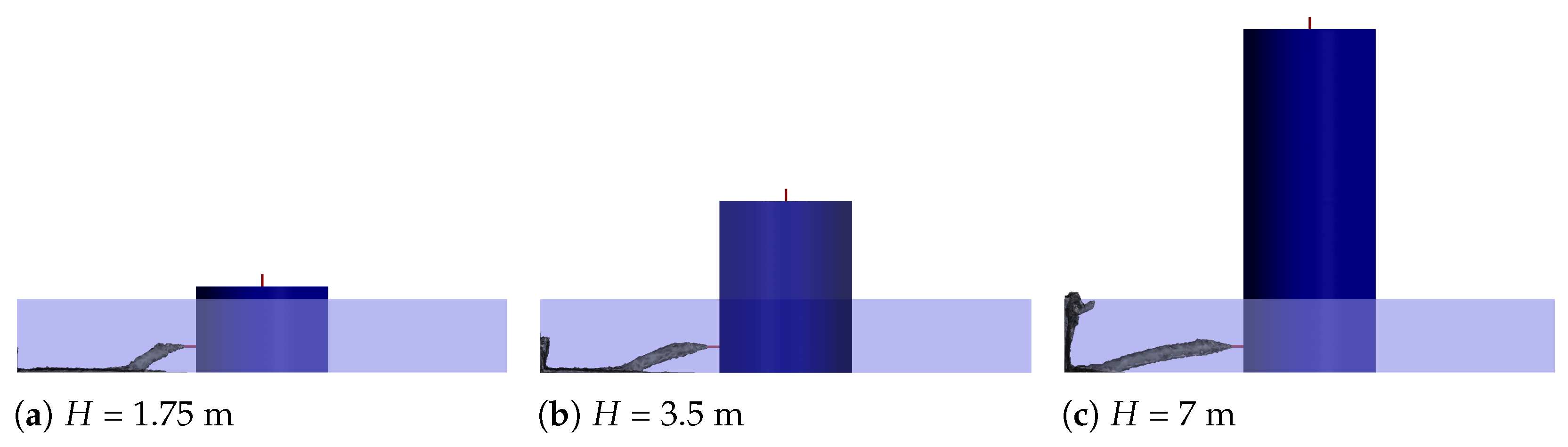
4. Numerical Results of Liquid Leakage

In this section, the numerical results obtained from simulations of liquid leakage in storage tanks of varying heights are presented and compared with the analytical results derived in Section 2. The study investigate the detection time of leaks at different detector positions, as well as the influence of separation distance at various tank heights and pressure force exerted on the bund wall, which is related to the overtopping fraction.

4.1. Detection Time Comparison for Various Tank Heights

Figure 5 displays the concentration contours of H 2 SO 4 from different viewpoints (isometric and top views) at various times for a tank height of h = 3.5 m. Initially, the liquid strikes the front bund wall, then spreads out to the corners before moving backward. For the placement of liquid leak detectors, it may be more effective to position the sensors at the corners rather than in close proximity to the storage tank, as depicted in the Figure 5f,g. At t = 10.7 s , all the monitoring points detected the sulfuric acid leak, except for MP 8, which is situated in the opposite direction of the leak.
Table 3 presents the results of a simulated sulfuric acid storage tank leak, with the detection time (hereafter denoted as t d ) at various monitoring points and the change in liquid level in storage tank (hereafter denoted as h l ) corresponding to t d for storage tanks of different heights (1.75 m, 3.5 m, and 7 m). The t d of MP 8 which is located opposite to MP 1 is almost 16 times longer than that of MP 1. The t d of MP 6 and 7 located on opposite sides of MP 2 and 3, shows a significant difference of two times compared to MP 2 and 3. This suggests a maximum potential change of 16 times depending on the position of the leak detector. Table 3 implies the detection time can be delayed depending on the location of the detection point or the direction of the leak. Therefore, relying solely on simple hardware-mounted detectors on the ground may entail significant uncertainty in early and proper detection of leaks.
Although, the detection time decreases as the height of the storage tank increases and the shortest detection time is observed in the 7 m tank, the amount of leakage is largest at the 7 m tank due to the highest hydrostatic pressure. In other words, h l , the liquid level change in the higher-storage tank, is highest at the detection of the same MP. Hence, it is crucial to detect as early as possible in the case of a higher-storage tank.
The average rate of liquid level change, d h l d t , for case 1, case 2, and case 3, is 1.25 mm/s, 1.82 mm/s, and 3.00 mm/s, respectively. The rate of liquid level change increases proportionally with the increase in the tank height, with a gradual upward trend. For all three cases, the liquid level changes more than 1 mm in 1 s and a liquid level sensor usually has a resolution of less than 1 mm [61]. Therefore, most cases of large leak accidents can be detected with the 1 mm resolution of level transmitter within a second. In particular, LT can be very useful for reducing detecting time in a large tank farm with multiple storage tanks because the chemical industries are compelled to install sensors at strategic locations such as catchment basins and establishing pathways like drainage due to the economic cost problem, which can cause the detecting time delay.
Figure 6 illustrates the time-dependent change in H 2 SO 4 volume fraction for case 1, case 2, and case 3 at different monitoring points. At MP 2 for case 3 in Figure 6a, the fluctuation appears due to the continuous inflow from the leak source and the conflict with bund wall. As the tank height increases, not only the detection time becomes shorter but the rate of volume fraction change becomes greater at the same monitoring points. Nevertheless, for all monitoring points in three cases, including MP 1, the detection time achieved by the level transmitter is consistently faster than that of any other monitoring point. Hence, incorporating a level transmitter or level measurement device in addition to point-type leak detectors can be an effective approach for prompt and precise leak detection.

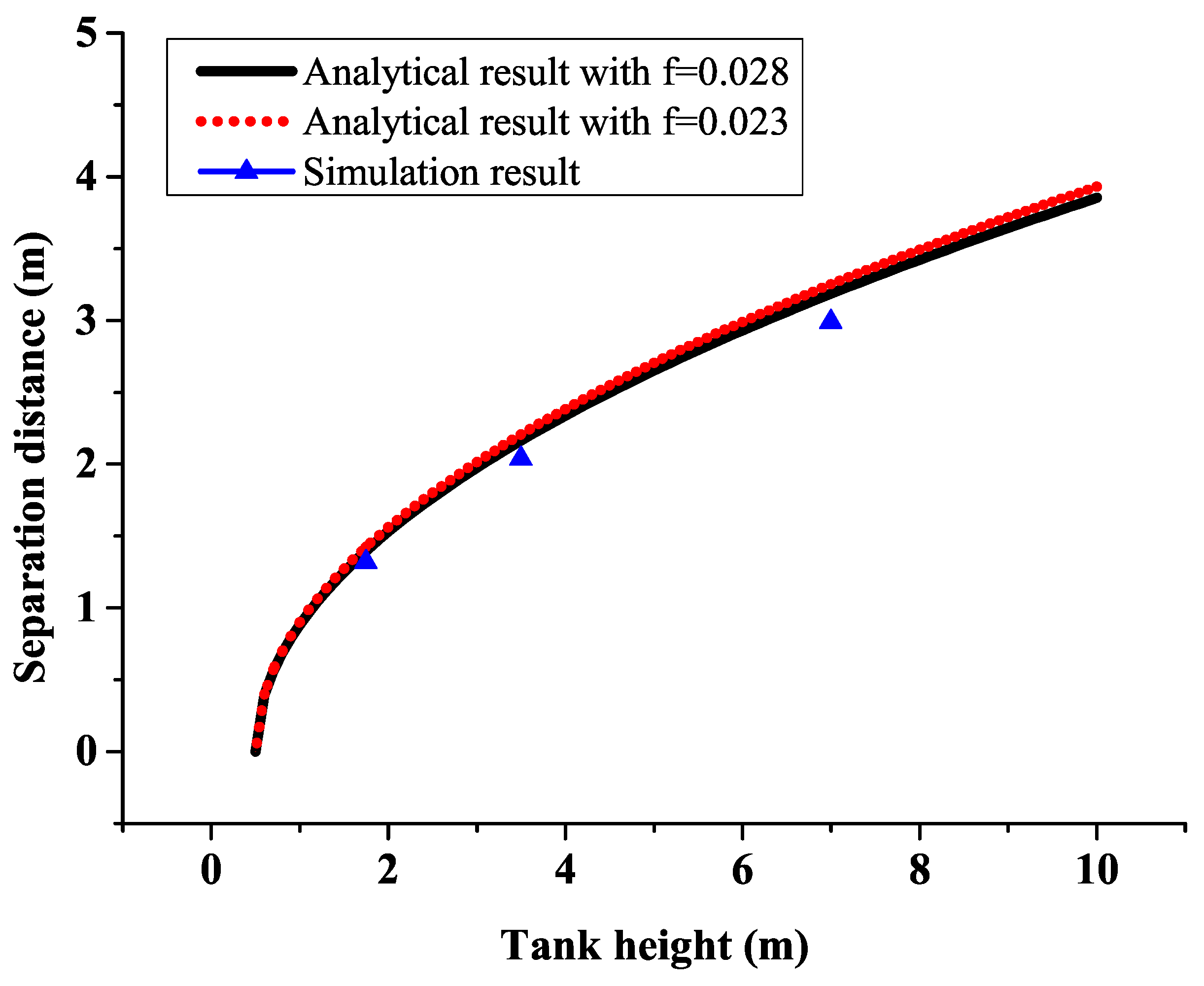
4.2. Results for Separation Distance at Various Tank Heights

The separation distance between a storage tank and its bund wall is influenced by the pressure forces acting on the liquid and can vary with changes in liquid level. In this study, the sulfuric acid leakage from storage tanks of different heights was simulated at three liquid levels ( 1.75 m, 3.5 m, and 7 m) as shown in Figure 7, and the resulting separation distances were measured and summarized in Table 4. It is observed that, as the tank height doubled, the separation distance does not increase proportionally, but rather increases in proportion to the square root of the liquid level from the leak point ( h 2 ), as shown in Figure 8.
The analytical results for separation distance in Equation (6) requires the Darcy–Weisbach friction factor which is determined by the Reynolds number and relative roughness in the Moody diagram. The Reynolds number is given by [62],
R e = V D ν
where ν is the kinematic viscosity and the value of sulfuric acid is 1.3 × 10 5   m 2 / s at 25 °C, V is the exit velocity at a leak point, and D is the diameter of a leak point.
The stainless steel absolute roughness, denoted as ϵ , has a value of 2 × 10 5 m [62], resulting in a relative roughness of ϵ D = 0.00004 . For tank heights of H = 1.75 m, H = 3.5 m, and H = 7.0 m, the average velocities at a leak point are 3.55 m/s, 6.2 m/s, and 9.28 m/s, respectively, yielding corresponding Reynolds numbers of 13,654, 23,846, and 35,692. Using the Moody diagram with R e and ϵ D , the obtained friction factor for case 1, case 2, and case 3 are determined to be 0.028, 0.025, and 0.023, respectively. Finally, the separation distance in the analytical solution can be obtained by substituting the friction factor and tank height into Equation (6).
Figure 8 shows the separation distance obtained from the simulation and analytical results. The simulation results of the separation distance, as presented in Table 4, are in good agreement with the analytical results obtained from Equation (6). Therefore, the current universally applied separation distance needs to take into account the variation depending on the height of the tank from the Equation (6).

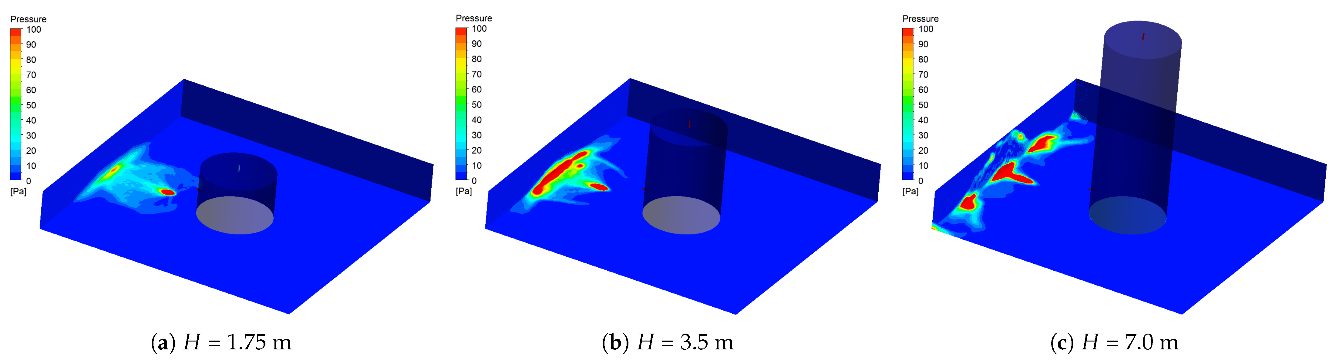
4.3. Results for Dynamic Pressure at Bund Wall

For the design of the bund, the reduction of the pressure on the bund wall is necessary since the overtopping fraction of liquids increases as the dynamic pressure increases [29]. The Figure 9 shows the pressure on side bund and bottom wall for three different tank heights ( h = 1.75 m, h = 3.5 m, and h = 7.0 m). As the height of the tank increases, the leakage velocity becomes larger, resulting in an increased horizontal displacement of the leaked substance. Moreover, the area of the bund wall exposed to high pressure also increases due to greater liquid contact. Table 5 summarizes the maximum pressure on the bund and bottom wall. In the case of a low tank height, P m a x on the bund wall is eight times smaller than that on the bottom wall. However, in the case of a high tank height, P m a x on the bund wall is similar to that on the bottom wall due to the horizontal distance of liquid movement being close to the separation distance from the bund wall. We observe that P m a x of case 3 increases significantly when the leaked liquid hits the bund wall directly or at close proximity, compared to the other two cases, case 1 and case 2, where the separation distance is adequate and the liquid does not reach the bund wall directly. Therefore, for the prevention of the damage on the bund wall and overtopping over the bund, it is important to secure a sufficient separation distance which is previously defined in Equation (6).

5. Conclusions

The implementation of rapid detection methods and the design of effective secondary containment systems play a crucial role in mitigating the spread of hazardous substances resulting from leaks. However, determining the optimal placement of detectors and installing them across extensive tank farms present significant challenges. In this study, our numerical simulations have provided valuable insights into the behavior of liquid leakage in storage tanks and the factors influencing it.
The simulation results revealed that the spread of hazardous liquids in storage tank bunds exhibits a distinctive circulation pattern along the corners of the bund wall upon reaching the ground. This observation provides crucial guidance for the optimal placement of leak sensors. Rather than situate the sensors in close proximity to the storage tank, a more effective strategy is to position them at the corners of the bund wall. Notably, the detection time at the opposite side of the leak point can be significantly delayed, up to 16 times longer than at the front position. In particular, the level transmitter consistently achieves faster detection times compared to the leak sensor at all monitoring points. The integration of a level transmitter alongside a leak detector offers a valuable approach to expedite leak detection, regardless of the direction or location of the leak. This approach is particularly beneficial for extensive tank farms housing multiple tanks, ultimately enhancing overall leak detection efficiency. Regarding the separation distance between the storage tank and bund wall, the optimal distance depends on both the total tank height and the height of the primary potential leak point. The analytical findings are in good agreement with the simulation results, with a remarkable match of up to 95%.
While the level transmitter exhibits faster detection capabilities compared to the leak sensor, further research is required to ensure its reliable operation as a detector. Optimization of the level transmitter’s logic and algorithm is necessary to effectively distinguish normal operational conditions from abnormal phenomena, thereby enhancing its overall functionality. The simulation conducted in this study assumed a flat bottom wall for the bund. However, in practical applications, it is crucial to conduct simulations that account for a sloping bottom topography.

Author Contributions

Conceptualization, S.J. and M.C.; methodology, S.J. and M.C.; software, S.J.; validation, S.J.; formal analysis, S.J. and M.C.; investigation, S.J. and M.C.; data curation, S.J. and M.C.; writing—original draft preparation, S.J. and M.C.; writing—review and editing, S.J. and M.C.; visualization, S.J. and M.C.; supervision, S.J.; project administration, S.J. All authors have read and agreed to the published version of the manuscript.

Funding

This research received no external funding.

Data Availability Statement

No new data were created or analyzed in this study. Data sharing is not applicable to this article.

Conflicts of Interest

The authors declare no conflict of interest.

References

  1. Belvederesi, C.; Thompson, M.S.; Komers, P.E. Statistical analysis of environmental consequences of hazardous liquid pipeline accidents. Heliyon 2018, 4, e00901. [Google Scholar] [CrossRef] [PubMed]
  2. Abbasi, T.; Abbasi, S.A. The boiling liquid expanding vapour explosion (BLEVE): Mechanism, consequence assessment, management. J. Hazard. Mater. 2007, 141, 489–519. [Google Scholar] [CrossRef] [PubMed]
  3. National Institute of Chemical Safety. Chemical accident statistics reports. In Chemical Substance Comprehensive Information System; National Institute of Chemical Safety: Cheongju, Republic of Korea, 2002. [Google Scholar]
  4. Hou, J.; Gai, W.; Cheng, W.; Deng, Y. Hazardous chemical leakage accidents and emergency evacuation response from 2009 to 2018 in China: A review. Saf. Sci. 2021, 135, 105101. [Google Scholar] [CrossRef]
  5. Donaldson, T. Case study 1: Tees Storage, Seal Sands, July 1999. In Loss Prevention Bulletin: Articles and Case Studies from around the World; Special Issue; Institution of Chemical Engineers: Rugby, UK, 2012. [Google Scholar]
  6. The Organization for Economic Cooperation and Development (OECD). OECD Guiding Principles for Chemical Accident Prevention, Preparedness and Response, 3rd ed.; Series on Chemical Accidents; The Organization for Economic Cooperation and Development (OECD): Paris, France, 2023; ISBN 978-92-64-90795-9. [Google Scholar]
  7. Santoso, B.; Indarto; Deendarlianto. Pipeline leak detection in two phase flow based on fluctuation pressure difference and artificial neural network (ANN). J. Appl. Mech. Mater. 2014, 493, 186–191. [Google Scholar] [CrossRef]
  8. Husain, M.A.; Zaki, N.M.; Mukhlas, N.A.; Ahmad, S.S.; Soom, E.M. Current practice of early leak detection methods for underground storage tanks. J. Phys. Conf. Ser. 2022, 2259, 012029. [Google Scholar]
  9. Britto, K.A.; Prasad, D.; Ragavendiran, S.P.; Shreepad, S.; Singh, N.K.; Bhowmick, A.; Ramkumar, M.S. Supervised Learning Algorithm for Water Leakage Detection through the Pipelines. In Proceedings of the 2022 3rd International Conference on Smart Electronics and Communication (ICOSEC), Trichy, India, 20–22 October 2022; pp. 1263–1269. [Google Scholar]
  10. Olszewska, A. Using the acoustic emission method for testing aboveground vertical storage tank bottoms. Appl. Acoust. 2022, 188, 108564. [Google Scholar] [CrossRef]
  11. El-Shiekh, T.M. Leak detection methods in transmission pipelines. Energy Sources A Recovery Util. Environ. Eff. 2010, 32, 715–726. [Google Scholar] [CrossRef]
  12. Williams, D.J.; Wadsworth, W.; Salvaggio, C.; Messinger, D.W. A hybrid thermal video and FTIR spectrometer system for rapidly locating and characterizing gas leak. Remote Sens. Aerosol Chem. Gases Model Simul./Assiumulation Appl. Air Qual. 2006, 6299, 108–111. [Google Scholar]
  13. Chen, C.; Tsow, F.; Campbell, K.D.; Iglesias, R.; Frozani, E.; Tao, N. A wireless hybrid chemical sensor for detection of envirnomnetal volatile organic compounds. IEEE Sens. J. 2013, 13, 1748–1755. [Google Scholar] [CrossRef]
  14. Vandrangi, S.K.; Lemma, T.A.; Mujtaba, S.M.; Ofei, T.N. Developments of leak detection, diagnostics, and prediction algorithms in multiphase flows. Chem. Eng. Sci. 2022, 248, 117205. [Google Scholar] [CrossRef]
  15. Meribout, M.; Khezzar, L.; Azzi, A.; Ghendour, N. Leak detection systems in oil and gas fields: Present trends and future prospects. Flow Meas. Instrum. 2020, 75, 101772. [Google Scholar] [CrossRef]
  16. Loizou, K.; Koutroulis, E. Water level sensing: State of the art review and performance evaluation of a low-cost measurement system. Measurement 2016, 89, 204–214. [Google Scholar] [CrossRef]
  17. Kim, H.Y.; Byun, S.H. A Study on the Improvement of Pressure Container Level Measurement Errors. Trans. Korean Inst. Electr. Eng. 2010, 59, 1889–1893. [Google Scholar]
  18. Secondary Containment Guidance, Michigan Department of Environment, USA. Available online: https://www.michigan.gov/-/media/Project/Websites/egle/Documents/Programs/MMD/Hazardous-Waste/Secondary-Containment-Guidance.pdf (accessed on 3 November 2023).
  19. Secondary Containment, Health and Safety Executive, UK. Available online: https://www.hse.gov.uk/comah/sragtech/techmeascontain.htm (accessed on 3 November 2023).
  20. Safety System for Pressurised Heavy Water Reactors, Atomic Energy Regulatory Board, India. Available online: https://aerb.gov.in/images/PDF/CodesGuides/NuclearFacility/NPPDesign/7.PDF (accessed on 3 November 2023).
  21. Nau, P.R.; Fultz, B.S. Coatings and linings for secondary chemical containment in power plants. J. Prot. Coat. Linings 1990, 7, 42–49. [Google Scholar]
  22. National Institute of Chemical Safety. Public Notice on the Installation and Management of Outdoor Storage Facilities for Hazardous Chemicals, 2022-13; National Institute of Chemical Safety: Cheongju, Republic of Korea, 2022.
  23. NFPA 30. Flammable and Combustible Liquids Code, National Fire Protection Association, USA. Available online: https://www.nfpa.org/codes-and-standards/3/0/30?l=729 (accessed on 3 November 2023).
  24. Barnes, D.S. The Design of Bunds; HSE: Merseyside, UK, 1990.
  25. Spill, Prevention, Control, and Countermeasure (SPCC), Environmental Protection Agency, USA. Available online: https://www.epa.gov/oil-spills-prevention-and-preparedness-regulations/spill-prevention-control-and-countermeasure-19 (accessed on 3 November 2023).
  26. Storage of Flammable Liquids in Tanks, HSG176, Health and Safety Executive, UK. Available online: https://www.hse.gov.uk/pubns/books/hsg176.htm (accessed on 3 November 2023).
  27. Chemical Substances Control Act, Ministry of Environment, Republic of Korea. Available online: https://www.law.go.kr/LSW/eng/engLsSc.do?menuId=2&section=lawNm&query=Chemical+Substances+Control+Act&x=0&y=0#liBgcolor1 (accessed on 3 November 2023).
  28. Lees, F. Lees’ Loss Prevention in the Process Industries: Hazard Identification, Assessment and Control, 4th ed.; Butterworth-Heinemann: Oxford, UK, 2012. [Google Scholar]
  29. Zhao, S.; Huo, J.; Xu, R.; Liu, Y.; Jing, M.; Zhang, B. Prevention of bund overtopping after a catastrophic tank failure accident: Effects of bund design, liquids and scale-up. Process Saf. Environ. Prot. 2022, 166, 41–56. [Google Scholar] [CrossRef]
  30. Luan, X.; Zhang, M.; Zhao, S.; Zhang, B. Numerical study on the effects of bund on liquid pool spreading and vapor dispersion after a catastrophic LNG tank failure. Process Saf. Environ. Prot. 2023, 176, 74–86. [Google Scholar] [CrossRef]
  31. Luan, X.; Huo, J.; Zhao, S.; Zhang, B. Risk Control of Overtopping Phenomenon after a Catastrophic Tank Failure Through Optimized Bund Design. Chem. Eng. 2022, 90, 433–438. [Google Scholar]
  32. Yaqoob, U.; Younis, M.I. Chemical Gas Sensors: Recent Developments, Challenges, and the Potential of Machine Learning—A Review. Sensors 2021, 21, 2877. [Google Scholar] [CrossRef]
  33. Bellegoni, M.; Ovidi, F.; Tempesti, L.; Mariotti, A.; Tognotti, L.; Landucci, G.; Galletti, C. Optimization of gas detectors placement in complex industrial layouts based on CFD simulations. J. Loss Prev. Process Ind. 2022, 80, 104859. [Google Scholar] [CrossRef]
  34. Vianna, S.S. The set covering problem applied to optimisation of gas detectors in chemical process plants. Comput. Chem. Eng. 2019, 121, 388–395. [Google Scholar] [CrossRef]
  35. Mohindru, P. Development of liquid level measurement technology: A review. Flow Meas. Instrum. 2023, 89, 102295. [Google Scholar] [CrossRef]
  36. Chemical Accident Prevention Provisions (CFR, Title 40, Chapter I, Subchapter C, Part 68), Environmental Protection Agency, USA. Available online: https://www.ecfr.gov/current/title-40/chapter-I/subchapter-C/part-68?toc=1 (accessed on 3 November 2023).
  37. European Committee for Standardization (CEN). Leak Detection Systems—Part 1: General Principles; CEN-CENELEC Management Centre: Brussels, Belgium, 2016. [Google Scholar]
  38. Design Guideline—Liquid Chemical Storage Tanks, Goulburn Valley Water: Shepparton, Australia. Available online: https://www.gvwater.vic.gov.au/Portals/0/GV-Water/Documents/Development-Construction-Manual/Design_Guideline_-_Liquid_Chemical_Storage_Tanks.pdf?ver=2019-10-25-161824-573 (accessed on 3 November 2023).
  39. Legg, S.W.; Benavides-Serrano, A.J.; Siirola, J.D.; Watson, J.P.; Davis, S.G.; Bratteteig, A.; Laird, C.D. A stochastic programming approach for gas detector placement using CFD-based dispersion simulations. Comput. Chem. Eng. 2021, 47, 194–201. [Google Scholar] [CrossRef]
  40. Underground Storage Tanks (USTs) Laws and Regulations, Environmental Protection Agency, USA. Available online: https://www.epa.gov/ust/underground-storage-tanks-usts-laws-and-regulations (accessed on 3 November 2023).
  41. Containment and Detection of Releases (CFR, Title 40, Chapter I, Subchapter I, Part 265, Subpart J, 265.193), Environmental Protection Agency, USA. Available online: https://www.ecfr.gov/current/title-40/chapter-I/subchapter-I/part-265/subpart-J/section-265.193 (accessed on 3 November 2023).
  42. Australian Institute of Petroleum (AIP). Guidelines for Safe above Ground Fuel Storage on Farms and Industrial Sites; Australian Institute of Petroleum (AIP): Canberra, Australia, 2003. [Google Scholar]
  43. Rules on Occupational Safety and Health Standards, Ministry of Employment and Labor, Republic of Korea. Available online: https://www.law.go.kr/LSW/eng/engLsSc.do?menuId=2&section=lawNm&query=Occupational+Safety+and+Health&x=0&y=0#liBgcolor1 (accessed on 3 November 2023).
  44. Clark, S.O.; Deaves, D.M.; Lines, I.G.; Henson, L.C. Effects of secondary containment on source term modelling. In Contract Research Report; WS Atkins Consultants Ltd.: London, UK, 2001; Volume 324. [Google Scholar]
  45. Malich, G.; Braun, M.; Loullis, P.; Winder, C. Comparison of regulations concerning hazardous substance from an international perspective. J. Hazard. Mater. 1998, 62, 143–159. [Google Scholar] [CrossRef]
  46. The Storage of Flammable Liquids in Containers, HSG51, Health and Safety Executive, UK. Available online: https://www.hse.gov.uk/pubns/books/hsg51.htm (accessed on 3 November 2023).
  47. Nair, S.R. Methods of avoiding tank bund overtopping using computational fluid dynamics tool. Insti. Chem. Eng. Symp. Ser. 2008, 154, 479. [Google Scholar]
  48. Liquid Storage and Handling Guidelines, Environment Protection Authority, Australia. Available online: https://www.epa.vic.gov.au/about-epa/publications/1698 (accessed on 3 November 2023).
  49. Bunding and Spill Management Guidelines, Environment Protection Authority, Australia. Available online: https://epa.tas.gov.au/Documents/Bunding_and_Spill_Management_Guidelines_Dec_2015.pdf (accessed on 3 November 2023).
  50. Health and Safety at Work Act 2015, Secondary Containment Systems, New Zealand. Available online: https://www.legislation.govt.nz/act/public/2015/0070/latest/DLM5976660.html (accessed on 3 November 2023).
  51. IPC Guidance Note on Storage and Transfer of Materials for Scheduled Activities, Environment Protection Authority, Ireland. Available online: https://www.epa.ie/publications/licensing--permitting/industrial/ied/IPC_Guidance_note_Materials_storage.pdf (accessed on 3 November 2023).
  52. Luan, X.; Huo, J.; Liu, Y.; Jiang, J.; Zhang, B. Predictive model of bund overtopping fraction for catastrophic failure of storage tank. Saf. Sci. 2020, 129, 104801. [Google Scholar] [CrossRef]
  53. Megdiche, I.; Atherton, W.; Allanson, D.; Harris, C. Effects of mitigation on the catastrophic faillure of storage tanks. J. Loss Prev. Process Ind. 2022, 80, 104852. [Google Scholar] [CrossRef]
  54. Megdiche, I. Evaluation of the Mechanical Strength of Bund Walls under the Catastrophic Failure of Strage Tanks via Fluid Structure Interaction. Ph.D. Thesis, Liverpool John Moores University, Liverpool, UK, 2019. [Google Scholar]
  55. Control of Fire-Water Run-Off from CIMAH Sites to Prevent Environmental Damage, EH70, Health and Safety Executive, UK. Available online: https://www.hse.gov.uk/pubns/books/eh70.htm (accessed on 3 November 2023).
  56. Kundu, P.K.; Cohen, I.M.; Dowling, D.R. Fluid Mechanics, 6th ed.; Academic Press: New York, NY, USA, 2015. [Google Scholar]
  57. Agboola, O.O.; Akinnuli, B.O.; Kareem, B.; Akintunde, M.A. Optimum detailed design of 13,000 m3 oil storage tanks using 0.8 height-diameter ratio. Mater. Today Proc. 2021, 44, 2837–2842. [Google Scholar] [CrossRef]
  58. Agboola, O.O.; Akinnuli, B.O.; Kareem, B.; Akintunde, M.A. Decision on the selection of the best height-diameter ratio for the optimal design of 13,000 m3 oil storage tank. Cogent Eng. 2020, 7, 1770913. [Google Scholar] [CrossRef]
  59. Batchelor, G.K. An Introduction to Fluid Dynamics, 1st ed.; Cambridge University Press: Cambridge, UK, 1967. [Google Scholar]
  60. ANSYS. Fluent User’s Guide; 2021R2 help system; Ansys, Inc.: Canonsburg, PA, USA, 2021. [Google Scholar]
  61. Wang, S.; Yang, Y.; Zhang, L.; Mohanty, L.; Jin, R.; Wu, S.; Lu, P. High-precision fiber optic liquid level sensor based on fast Fourier amplitude demodulation in a specific range of spectrum. Measurement 2022, 187, 110326. [Google Scholar] [CrossRef]
  62. Fox, R.W.; McDonald, A.T.; Mitchell, J.W. Introduction to Fluid Mechanics, 10th ed.; Wiley: New York, NY, USA, 2020. [Google Scholar]
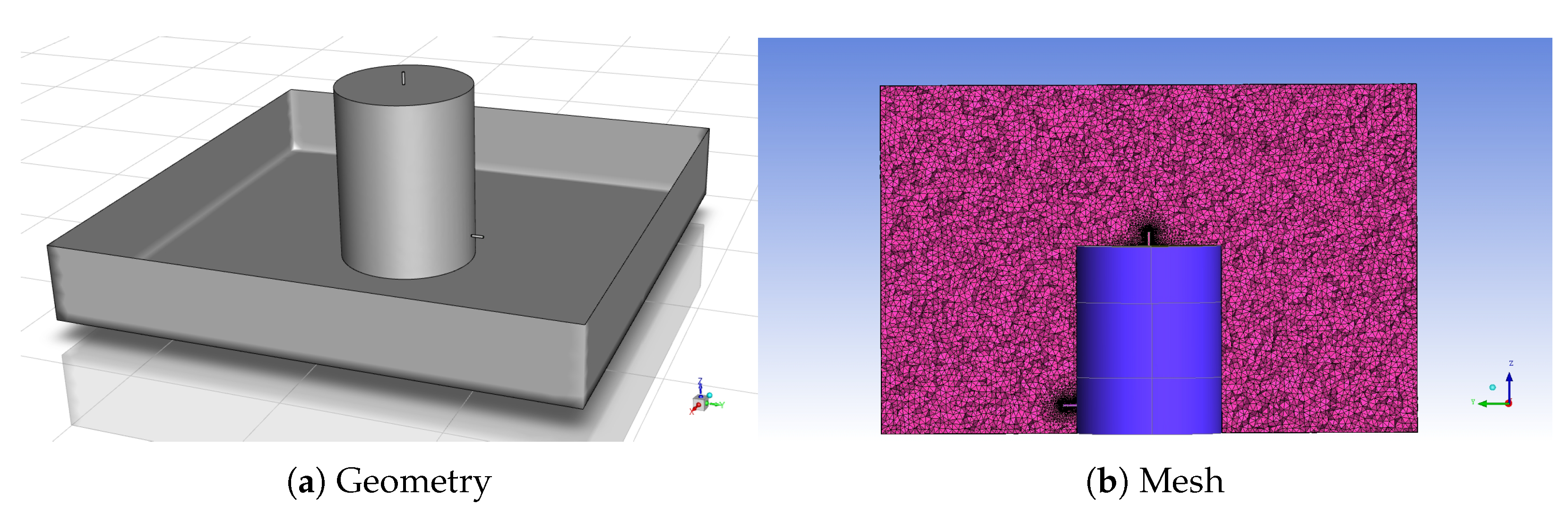
Figure 1. Summary of current regulations for leak detection and bund wall.
Processes 11 03179 g001
Figure 2. Storage tank leakage dimensional diagram.
Processes 11 03179 g002
Figure 3. Geometry and mesh.
Processes 11 03179 g003
Figure 4. Detector location.
Processes 11 03179 g004
Figure 5. Concentration contours of H 2 SO 4 in isometric view (ad) and top view (eh) for a tank height of h = 3.5 m at various times.
Processes 11 03179 g005
Figure 6. H 2 SO 4 volume fraction plots in time for a tank height of H = 1.75 m (black solid line), H = 3.5 m (red dotted line), and H = 7.0 m (blue dashed line) at various monitoring points.
Processes 11 03179 g006
Figure 7. Separation distance at various tank heights.
Processes 11 03179 g007
Figure 8. Comparison of separation distance for analytical and simulation results.
Processes 11 03179 g008
Figure 9. Pressure contour of bund and bottom wall for three different tank heights ( h = 1.75 m, h = 3.5 m, and h = 7.0 m) at t = 2 s .
Processes 11 03179 g009
Table 2. Simulation conditions for three different cases at the tank height of 1.75 m, 3.5 m, and 7.0 m.
Tank HeightDomain Size (x, y, z)Mesh ElementsTank DiameterLeak Diameter
Case 11.75 m10 m, 10 m, 4.25 m3,809,1752.7 m50 mm
Case 23.5 m10 m, 10 m, 6.5 m7,298,610
Case 37.0 m10 m, 10 m, 9.5 m8,283,985
Table 3. Detection time and liquid level change at eight monitoring points.
LocationCase 1Case 2Case 3
t d ( s ) h l ( mm ) t d ( s ) h l ( mm ) t d ( s ) h l ( mm )
1.01.180.71.270.51.44
➁, ➂2.93.542.23.961.85.31
➃, ➄6.37.814.68.353.39.83
➅, ➆10.913.627.513.665.315.83
14.317.8911.320.618.124.26
Table 4. Separation distance comparison between the analytical and simulation results.
VariableResult ComparisonCase 1Case 2Case 3
L s ( m ) Analytical result1.402.193.25
Simulation result1.322.042.99
Table 5. Maximum pressure at the bund wall and bottom wall for the various tank heights.
LocationCase 1Case 2Case 3
P m a x ( P a )bottom wall74310354352
bund (side) wall954243545
Disclaimer/Publisher’s Note: The statements, opinions and data contained in all publications are solely those of the individual author(s) and contributor(s) and not of MDPI and/or the editor(s). MDPI and/or the editor(s) disclaim responsibility for any injury to people or property resulting from any ideas, methods, instructions or products referred to in the content.

