1. Introduction
As a simple and economical supporting structure, bolts play an important role in the field of geotechnical support [
1,
2,
3,
4]. After long-term development and engineering inspection, end anchoring, extended anchoring, and full-length anchoring have become the main types of bolt support [
5,
6,
7,
8]. The requirements for bolt support in roadway reinforcement are heightened due to the impact of rock separation. In the case of bed separation, the bed separation size often reflects the quality of bolt support [
9]. When the bed separation size is too large, the additional stress generated will often cause the anchorage interface to peel or even the whole slip failure [
10]. Compared with end anchorage, extended anchorage and full-length anchorage have longer bond interfaces and are more sensitive to bed separation, so they are the most widely used in roadway support.
Due to the different anchoring lengths and preload [
10], the supporting performance of the end anchor bolt, the extended anchor bolt and the full-length anchored bolt are different under the same conditions. In order to fully grasp the difference in support performance of the end anchor bolt, the extended anchor bolt and the full-length anchored bolt, scholars at home and abroad carried out a lot of research work. Wang Guanghui [
6] used the methods of theoretical analysis, numerical simulation and field test to study the stress distribution law of the end anchor bolt, the extended anchor bolt and the full-length anchored bolt, the bearing characteristics of bolts and the interaction mechanism of bolt-anchoring agent and surrounding rock during the process of joint opening and shear slip. Several researchers [
11,
12] carried out a comparative study of the full-length anchored bolt and the end-anchor bolt and concluded that the full-anchor had a better anchoring effect than the end-anchor, and anchoring agent and anchor bolt could jointly resist rock deformation and more effectively prevent the stratified dislocation of surrounding rock. A conclusion has been drawn that a certain length of free section should be left to ensure the play of preload while ensuring sufficient anchoring length [
13]. Furthermore, a comparative analysis of the stress characteristics of the anchorage section under the two main anchoring methods, end anchor and full-length anchorage, through theoretical analysis, numerical simulation analysis, and field tests was also conducted [
14]. Aiming at weak surrounding rock, resin anchoring and mine bolt support system, a multi-function bolt pulling test system to study and reveal the mechanical characteristics of coal mine bolt pulling under the different anchoring lengths has been adopted [
15].
In summary, the existing research literature mainly focuses on the influence of anchoring length on the supporting performance under the same anchoring mode and the influence of different anchoring modes on the supporting performance, which has the following shortcomings. The influence of anchoring mode and preload on supporting performance was not considered comprehensively. This research was designed to find out the difference in the stress characteristics and reinforcement effect on surrounding rock under the typical bed separation conditions among the lengthened anchored pre-stressed bolt, the full-length anchored bolt and the full-length anchored pre-stressed bolt. On the basis of existing studies, the mechanical model and numerical model of the three typical bolts were established in this paper to reveal, respectively, the influence laws of the preload, the bed separation value, the bed separation number and the bed separation position on the supporting performance, and provide a theoretical basis for the selection of anchor bolt.
2. Mechanical Model of the Three Typical Bolts
2.1. Mechanical Model of Lengthened Anchored Pre-Stressed Bolt
The lengthened anchored pre-stressed bolt refers to the anchoring length of 30% to 90% of the total length of the bolt. Studies indicated that the lengthened anchored pre-stressed bolt could provide high preload and provide better support for the deep broken surrounding rock [
16].
Figure 1 shows the basic structure of the lengthened anchored pre-stressed bolt under the action of the bed separation. In the Figure,
L is the total length of the bolt,
L1 is the length of the free section,
L2 is the length of the anchoring section,
F is the preload, and
b is the bed separation value.
Through an elastic analysis of the pretension load transfer mechanism [
17], we can show that the shear stress and axial force generated by the preload
F on the anchorage section
L2 of the bolt body were as follows:
where
Q is the preload force exerted on the bolt,
L is the total length of the bolt,
L1 is the length of the free section,
L2 is the length of the anchoring section,
x is the distance from the end of the anchoring section,
β is the coefficient related to anchor rod and surrounding rock,
,
K is the shear stiffness coefficient of surrounding rock,
Ea is the complex elastic modulus,
, experessed in GPa,
Eb is the elastic modulus of bolt,
Eg is the elastic modulus of slurry,
d is the diameter of bolt, and
D is the diameter of the anchor solid.
If the bed separation occurs in the free section of the bolt, the axial force and shear stress on the anchoring section were still calculated by Equations (1) and (2), and only
F is replaced by
F0, where
F0 is the axial force on the free section of the bolt under the action of the bed separation. If the bed separation occurs in the anchoring section of the bolt, the anchoring section under the action of the bed separation can be regarded as the superposition of the anchoring section under the action of the preload and the anchoring section under the action of the bed separation [
18]. The axial force and shear stress of the lengthened anchored pre-stressed bolt under the action of the bed separation were as follows:
When
,
where
x0 is the distance between the bed separation and the left end of the bolt;
can be calculated by the equation
}.
2.2. Mechanical Model of Full-Length Anchored Bolt
Full-length anchored bolts were widely used in ground geotechnical engineering and underground coal mine engineering [
19].
Figure 2 shows the basic structure of the full-length anchored bolt under the action of the bed separation. In
Figure 2,
L is the total length of the bolt, and
b is the bed separation value.
Ding Xiao [
20] derived the axial force and interfacial shear stress expressions of the full-length anchored bolt with elastic condition by taking the bed separation value as the sum of relative displacements between anchor solids and surrounding rock on the left and right sides of the bed separation according to the shear slip theory of anchorage interface.
2.3. Mechanical Model of Full-Length Anchored Pre-Stressed Bolt
The full-length anchored pre-stressed bolt had the characteristics of both the end anchor bolt and the full-length anchored bolt, which could not only apply preload but also realise a full-length anchor, so it was more and more widely used in the support field.
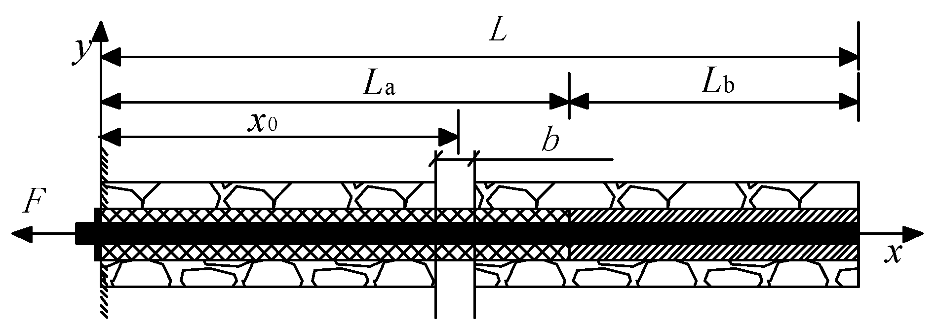
Figure 3 shows the basic structure of the full-length anchored pre-stressed bolt under the action of the bed separation. In
Figure 3,
L is the total length of the bolt,
La is the length of the secondary bonding section,
Lb is the length of the initial bonding section,
F is the preload force, and
b is the value of the bed separation.
The full-length anchored pre-stressed bolt under the action of the bed separation was regarded as the superposition of the end-anchored pre-stressed bolt and the full-length anchored bolt under the action of the bed separation [
21,
22], and the axial force and interfacial shear stress expressions were derived by the superposition principle.
3. Establishment of the Numerical Model
3.1. Numerical Model Scheme
The model was composed of four blocks with a side length of 1 m, and the relative displacement between blocks was used to simulate the separation of layers, as shown in
Figure 4. The diameter of the three typical bolts is 20 mm, and the parameters of bolts, blocks and pallets are shown in
Table 1 and
Table 2 [
23,
24]. The cable structural unit in FLAC3D was used to build the model, the shell structural unit was used to simulate the tray at the left end of the bolt, and the bolt was divided into 38 units. The lateral speed was applied to the block to simulate the crack opening, and the tension speed was determined to be 1 × 10
−6 m/step (to ensure the quasi-static state).
To simulate the progressive de-anchoring failure of bolts, a sliding failure algorithm was developed by using Fish language. Under the action of the bed separation, when the anchorage interface shear reached the bonding force of the anchorage interface in the model parameters, it was considered that the bolt began to slip. The bonding force and bonding stiffness of the bolt element were assigned as 0, and the algorithm would be implemented in each calculation step so as to realise the progressive sliding failure of the bolt.
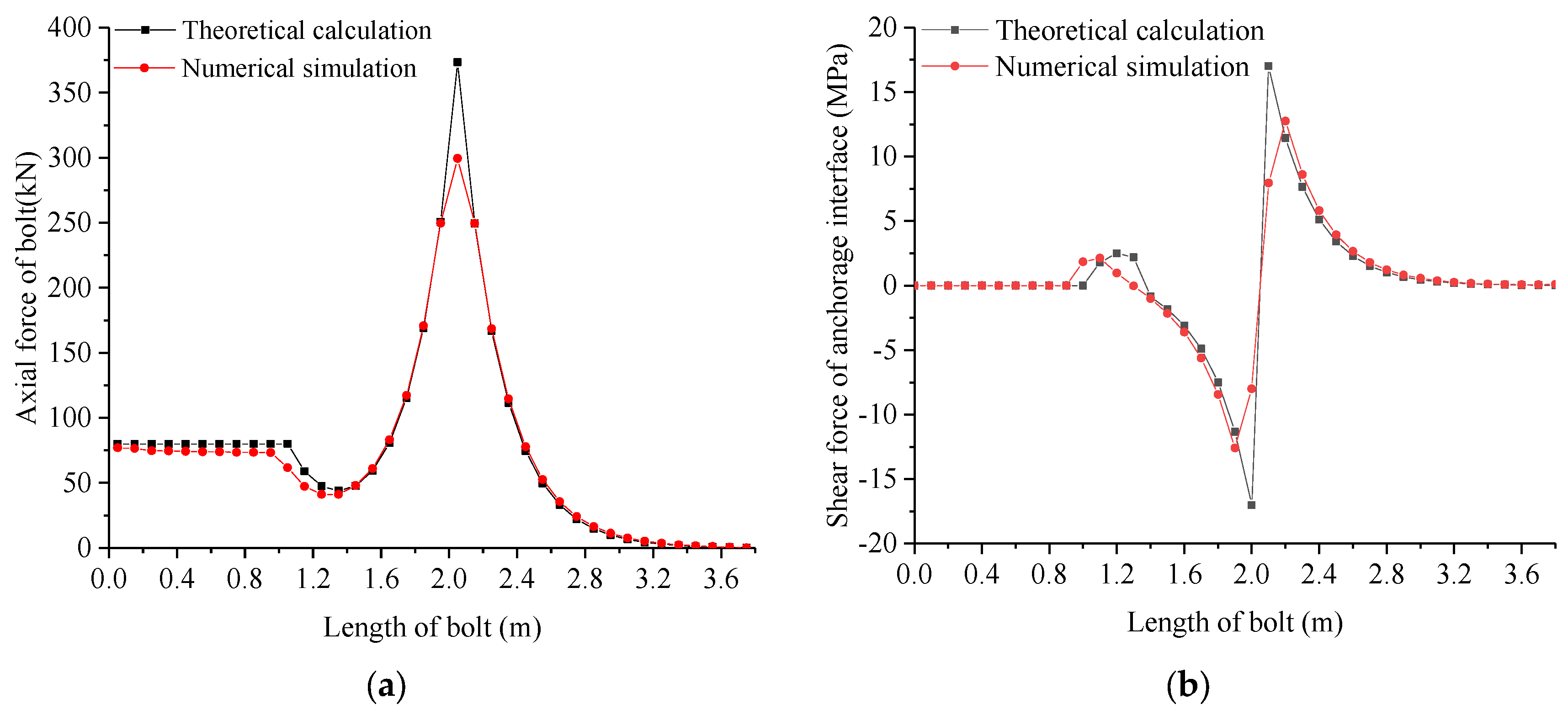
3.2. Model Verification
In FLAC3D, it was assumed that the middle fracture occurred among the lengthened anchored pre-stressed bolt, the full-length anchored bolt and the full-length anchored pre-stressed bolt, and the bed separation value was 3 mm. The pretension force was 80 kN, the elastic modulus of the anchoring agent was 5 GPa, and the diameter of the drilling hole was 28 mm. The axial force and interfacial shear stress of bolts were calculated by the theoretical formula and the numerical simulation method, respectively. As shown in
Figure 5,
Figure 6 and
Figure 7, the theoretical calculation results were in good agreement with the numerical simulation results, indicating that it was feasible to use the numerical simulation method to study the differences in the mechanical properties of the three typical bolts.
4. Discussion
4.1. Comparison of Mechanical Characteristics of Bolts without Bed Separation
The preload was 30 kN, 50 kN and 80 kN, respectively, and the full-length anchored bolt had no preload. The numerical simulation results are shown in
Figure 8. In the figures, Lapb represents a lengthened anchored pre-stressed bolt, Fapb represents a full-length anchored pre-stressed bolt, and Flab represents a full-length anchored bolt, the same as below.
It can be seen from
Figure 8a that (1) the axial force of the lengthened anchored pre-stressed bolt in the free section was slightly less than the preload, and the axial force of the bolt in the anchoring section showed exponential attenuation. (2) The axial force of the full-length anchored pre-stressed bolt was slightly less than the preload on the secondary bonding section, and the axial force of the bolt showed exponential attenuation on the initial bonding section. (3) Under the action of different preloads, the axial force distribution of the lengthened anchored pre-stressed bolt and the full-length anchored pre-stressed bolt all presented a change law from constant value to exponential attenuation. (4) The axial force distribution range of the full-length anchored pre-stressed bolt was larger.
It can be seen from
Figure 8b that (1) the shear stress of the lengthened anchored pre-stressed bolt was zero in the free section, and it exhibited an initial increase followed by a subsequent decrease in the anchorage section. The greater the preload, the greater the maximum shear stress at the anchorage interface. (2) The shear stress of the full-length anchored pre-stressed bolt was zero at the secondary bonding section, and it exhibited an initial increase followed by a subsequent decrease at the initial bonding section. The greater the preload, the greater the maximum shear stress at the anchorage interface. (3) Under the action of different preloads, the shear stress distribution of the lengthened anchored pre-stressed bolt and the full-length anchored pre-stressed bolt all presented a three-stage change law of zero section, increasing section and exponential decay section.
4.2. Comparison of Mechanical Characteristics of Bolts with Bed Separation
The bed separation was set as left fracture, whose value was 3 mm. The preload was 30 kN, 50 kN, and 80 kN, while the full-length anchored bolt had no preloading force. The numerical simulation results are shown in
Figure 9.
It can be seen from
Figure 9a that (1) the axial force of the lengthened anchored pre-stressed bolt presented a four-stage change law of constant value, decreasing, increasing, and decreasing; the axial force of the full-length anchored pre-stressed bolt presented a three-stage change law of constant value, increasing, and decreasing; and the axial force of the full-length anchored bolt presents a two-stage change law of increasing and decreasing. (2) At the bed separation, the axial force of the three kinds of bolt all reached the maximum value. (3) For the lengthened anchored pre-stressed bolt, when the preload was 30, 50, and 80 kN, the maximum axial force was 298.7, 299.1, and 299.5 kN, respectively. For the full-length anchored pre-stressed bolt, when the preload was 30, 50, and 80 kN, the maximum axial force was 327.5, 347.3, and 376.2 kN, respectively. For the full-length anchored bolt, the maximum axial force was 298.6 kN.
It can be seen from
Figure 9b that (1) the shear stress of the lengthened anchored pre-stressed bolt presented a five-stage change law of constant value, increase, decrease, increase, and decrease; the full-length anchored pre-stressed bolt presented a five-stage change law of decrease, increase, decrease, increase, and decrease; and the full-length anchored bolt presented a three-stage change law of decrease, increase, and decrease. (2) On both sides of the bed separation, the shear stress value was reversed, and the shear stress at the bed separation reached the maximum value. (3) When the preload was different, the maximum shear stress value of the three typical bolts was always 12.7 MPa.
5. Comparative Study on the Mechanical Characteristics of Bolts under the Bed Separation Conditions
5.1. Comparison of Mechanical Characteristics of Bolts with Different Bed Separation Values
The bed separation was set as left fracture, whose value was 3, 5, and 8 mm. The preload was set to 80 kN, while the full-length anchored bolt had no preload. The numerical simulation results are shown in
Figure 10.
It can be seen from
Figure 10a that (1) the axial force of the lengthened anchored pre-stressed bolt presented a four-stage change law of constant value, decreasing, increasing, and decreasing; the axial force of the full-length anchored pre-stressed bolt presented a three-stage change law of constant value, increasing, and decreasing; and the axial force of the full-length anchored bolt presented a two-stage change law of increasing and decreasing. (2) At the bed separation, the axial force of the three typical bolts reached the maximum value. (3) When the separation value was 3 mm, there were no sliding elements in three typical bolts. When the bed separation value was 5 and 8 mm, the number of slip units of the lengthened anchored pre-stressed bolt was 3 and 8, that of the full-length anchored pre-stressed bolt was 3 and 8, and that of the full-length anchored bolt was 2 and 9, respectively. (4) For the lengthened anchored pre-stressed bolt, when the bed separation value was 3, 5, and 8 mm, the maximum axial force was 299.5, 335.0, and 350.3 kN, respectively; for the full-length anchored pre-stressed bolt, when the bed separation value was 3, 5, and 8 mm, the maximum axial force was 376.2, 411.7, and 425.8 kN, respectively; for the full-length anchored bolt, when the bed separation value was 3, 5, and 8 mm, the maximum axial force was 298.6, 372.4, and 328.1 kN, respectively.
It can be seen from
Figure 10b that (1) the shear stress of the lengthened anchored pre-stressed bolt presented a five-stage change law of constant value, increase, decrease, increase, and decrease; the full-length anchored pre-stressed bolt presented a five-stage change law of decrease, increase, decrease, increase, and decrease; and the full-length anchored bolt presented a three-stage change law of decrease, increase and decrease. (2) On both sides of the bed separation, the shear stress value was reversed, and the shear stress on both sides of the bed separation reached the maximum value. (3) For the lengthened anchored pre-stressed bolt, when the bed separation value was 3, 5, and 8 mm, the maximum shear stress was 12.7, 15.1, and 15.6 MPa, respectively; for the full-length anchored pre-stressed bolt, when the bed separation value was 3, 5, and 8 mm, the maximum shear stress was 12.7, 14.8, and 16.1 MPa, respectively; for the full-length anchored bolt, when the bed separation value was 3, 5, and 8 mm, the maximum shear stress was 12.8, 16.5, and 14.4 MPa, respectively.
It can be seen from the distribution law of axial force that the peak axial force of the three typical bolts changed with the change in the bed separation value, and the peak axial force value of the full-length anchored pre-stressed bolt was the largest. From 3 mm to 5 mm, the maximum axial force increased by 11.9% (Lapb), 9.4% (Fapb), and 24.7% (FLab), respectively. From 5 mm to 8 mm, the maximum axial force of the bolt increased by 4.6% (Lapb), 3.4% (Fapb), and −11.9% (FLab), respectively. It can be seen from the distribution law of shear stress that the shear stress distribution interval of the three typical bolts was basically the same, and the shear stress was zero in the de-anchoring interval. The lengthened anchored pre-stressed bolt increased first and then decreased at the left end of the anchoring section, and the full-length anchored pre-stressed bolt increased first and then decreased at the left end of the initial bonding section. When the bed separation value was from 3 mm to 5 mm, the maximum shear stress increased by 18.9%, 16.5%, and 28.9%, respectively. When the bed separation value was from 5 mm to 8 mm, the maximum shear stress increased by 3.3%, 8.8%, and −12.7%, respectively.
5.2. Comparison of Mechanical Characteristics of Bolts with Bed Separation
Under three bed separation conditions, the cracks opened 2, 2, 1 mm and 4, 3, 2 mm, respectively. The preload was set at 80 kN, while the full-length anchored bolt had no preload. The numerical simulation results are shown in
Figure 11.
It can be seen from
Figure 11a that (1) in the working conditions of three bed separation, the axial force curves of the two kinds of full-length anchored bolts showed three peaks, and the greater the bed separation value, the greater the axial force peak; the axial force curves of the lengthened anchored pre-stressed bolt showed two peaks and a constant value on the free section. (2) When the crack opened 2, 2, 1 mm, the three axial force characteristic values of the lengthened anchored pre-stressed bolt were 126.0, 248.9, and 113.3 kN, respectively; the three axial force peaks of the full-length anchored pre-stressed bolt were 319.0, 326.6, and 155.6 kN, respectively. The three axial force peaks of the full-length anchored bolt were 244.5, 250.2, and 110.1 kN, respectively. (3) When the crack opened 4, 3, 2 mm, the three axial force characteristic values of the lengthened anchored pre-stressed bolt were 177.4, 321.9, and 248.1 kN, respectively. The three axial force peaks of the full-length anchored pre-stressed bolt were 414.2, 399.4, and 295.4 kN, respectively. The three axial force peaks of the full-length anchored bolt were 307.6, 327.2, and 244.9 kN, respectively. (4) When the crack opened 2, 2, 1 mm, there were no sliding elements in all three typical bolts. When the crack opened 4, 3, 2 mm, the full-length anchored pre-stressed bolt had 1 slip element at the left bed separation, and the full-length anchored bolt had 2 slip elements at the left bed separation.
It can be seen from
Figure 11b that (1) corresponding to the axial force curve, the shear stress of the two kinds of full-length anchored bolts reached its maximum at the peak axial force. (2) When the crack opened 2, 2, 1 mm, the shear stress characteristic values of the lengthened anchored pre-stressed bolt were 4.3, 12.2, and 5.7 MPa, respectively. When the crack opened 2, 2, 1 mm, the shear stress peaks of the full-length anchored pre-stressed bolt were 12.4, 12.0, and 7.8 MPa, respectively. When the crack opened 2, 2, 1 mm, the shear stress peaks of the full-length anchored bolt were 12.3, 11.9, and 11.9 MPa, respectively. (3) When the crack opened 4, 3, 2 mm, the shear stress characteristic values of the lengthened anchored pre-stressed bolt were 6.3, 13.4, and 12.5 MPa, respectively. When the crack opened 4, 3, 2 mm, the shear stress peaks of the full-length anchored pre-stressed bolt were 14.8, 12.8, and 14.8 MPa, respectively. When the crack opened 4, 3, 2 mm, the shear stress peaks of the full-length anchored bolt were 13.3, 13.1, and 12.6 MPa, respectively.
5.3. Comparison of Mechanical Characteristics of Bolts with Different Bed Separation Positions
The bed separation was set to the left, middle and right fracture, respectively, and the bed separation value was set to 5 mm. The preload was set at 80 kN, while the full-length anchored bolt had no preload. The numerical simulation results are shown in
Figure 12.
It can be seen from
Figure 12a that (1) the axial force of the three typical bolts at the bed separation reached the maximum value. (2) When being the left bed separation, the maximum axial force of the lengthened anchored pre-stressed bolt was 206.3 kN, that of the full-length anchored pre-stressed bolt was 448.7 kN, and that of the full-length anchored bolt was 333.8 kN. When being the middle bed separation, the maximum axial force of the lengthened anchored pre-stressed bolt was 411.7 kN, that of the full-length anchored pre-stressed bolt was 448.7 kN, and that of the full-length anchored bolt was 372.4 kN. When being the right bed separation, the maximum axial force of the lengthened anchored pre-stressed bolt was 372.4 kN, that of the full-length anchored pre-stressed bolt was 300.2 kN, and that of the full-length anchored bolt was 330.2 kN. (3) When being the left bed separation, the sliding elements number of the lengthened anchored pre-stressed bolt was zero, that of the full-length anchored pre-stressed bolt was 2, and that of the full-length anchored bolt was 3. When being the middle bed separation, the sliding elements number of the lengthened anchored pre-stressed bolt was 3, that of the full-length anchored pre-stressed bolt was 3, and that of the full-length anchored bolt was 2. When being the right bed separation, the sliding elements number of the lengthened anchored pre-stressed bolt was 2, that of the full-length anchored pre-stressed bolt was 5, and that of the full-length anchored bolt was 3.
It can be seen from
Figure 12b that (1) when the bed separation position was different, the shear stress value of the three typical bolts was reversed on both sides of the bed separation, and the shear stress on both sides of the bed separation reached the maximum value. (2) When being the left bed separation, the maximum shear stress of the lengthened anchored pre-stressed bolt was 8.5 MPa, and that of the full-length anchored pre-stressed bolt was 16.6 MPa, and that of the full-length anchored bolt was 14.7 MPa. When being the middle bed separation, the maximum shear stress of the lengthened anchored pre-stressed bolt was 15.1 MPa, that of the full-length anchored pre-stressed bolt was 14.8 MPa, and that of the full-length anchored bolt was 16.5 MPa. When being the right bed separation, the maximum shear stress of the lengthened anchored pre-stressed bolt was 16.7 MPa, and that of the full-length anchored pre-stressed bolt was 15.9 MPa, and that of the full-length anchored bolt was 15.3 MPa.
From the distribution of axial force, it could be seen that the axial force peak value of the three typical bolts had a great difference when the bed separation position was different. The peak axial force of the full-length anchored pre-stressed bolt was the largest when being the left and middle bed separation. The axial force peak of the lengthened anchored pre-stressed bolt was the largest when being the right bed separation. The sliding element numbers of the three typical bolts differed greatly when being the right bed separation, and the risk of de-anchoring the full-length anchored pre-stressed bolt was the greatest. It could be seen from the distribution law of shear stress that the shear stress distribution interval of the three typical bolts was basically the same, and the shear stress was zero in the de-anchoring interval. The shear stress of the lengthened anchored pre-stressed bolt increases first and then decreases at the left end of the anchoring section, and that of the full-length anchored pre-stressed bolt increases first and then decreases at the left end of the initial bonding section.
6. Comparative Study on Supporting Performance
6.1. Comparison of Reinforcement Effect of Initial Preload
Under the action of preload, the surrounding rock in the support range was compressed, resulting in compressive deformation that was an important basis for measuring the bolting performance.
Figure 13,
Figure 14 and
Figure 15 show the X-direction displacement cloud map of surrounding rock under the different preload. It can be seen from the figures that (1) under the same preload condition, the compression deformation range of surrounding rock caused by the full-length anchored pre-stressed bolt was significantly larger than that caused by the lengthened anchored pre-stressed bolt. (2) When the preload was 30 kN, the maximum displacement of the left end of the surrounding rock was 0.0104 mm (Lapb) and 0.0093 mm (Flpb), respectively. When the preload was 50 kN, the maximum displacement of the left end of the surrounding rock was 0.0174 mm (Lapb) and 0.0154 mm (Flpb), respectively. When the preload was 80 kN, the maximum displacement of the left end of the surrounding rock was 0.0278 mm (Lapb) and 0.0247 mm (Flpb), respectively. (3) Under the same bolt condition, the compressive deformation range of surrounding rock increased with the increase of preload. (4) Due to the different action way of preload, the tensile deformation of surrounding rock caused by the lengthened anchored pre-stressed bolt was mainly distributed in the middle of the model, while that caused by the full-length anchored pre-stressed bolt was mainly distributed in the right end of the model.
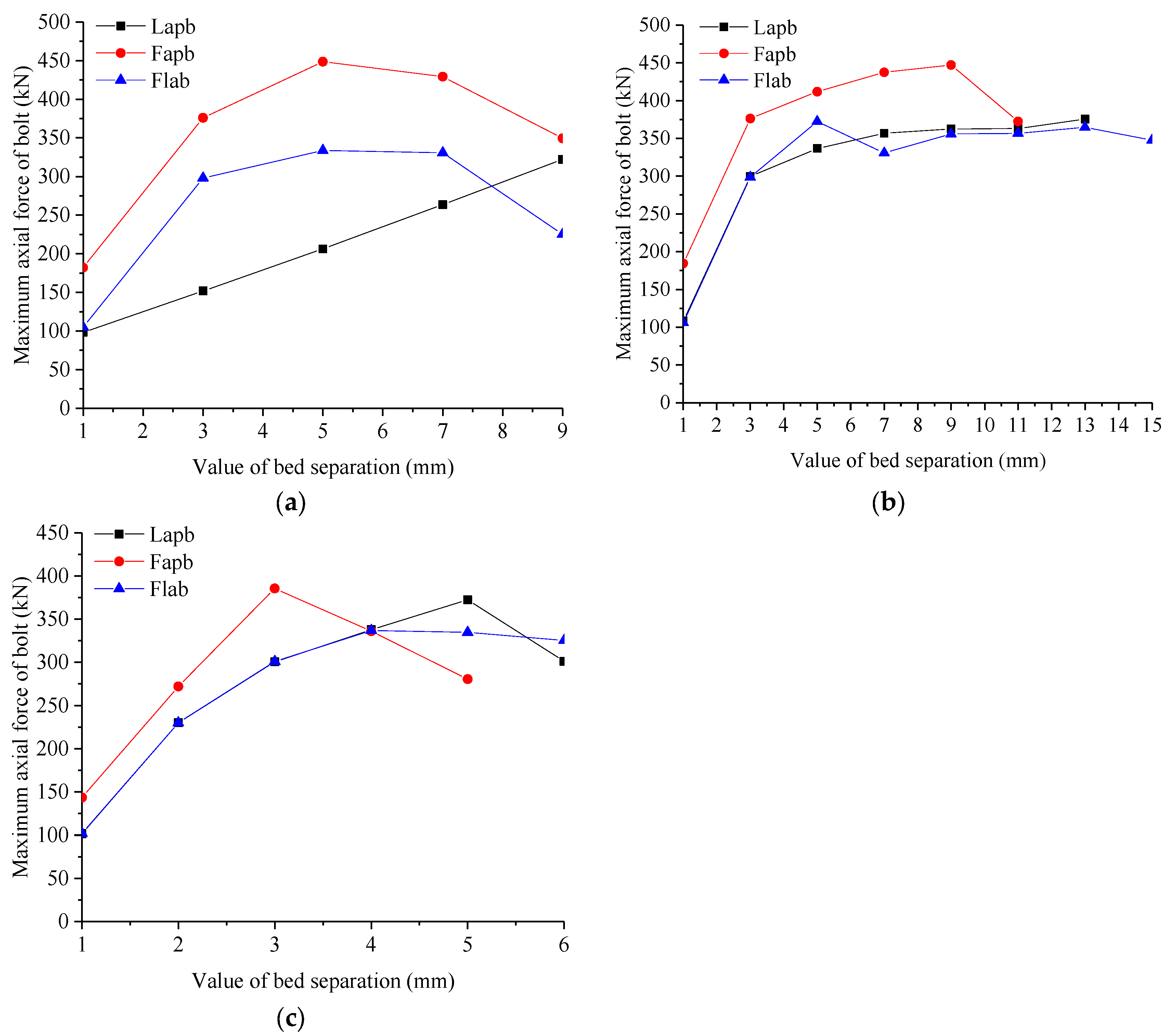
6.2. Sensitivity Analysis of Perceived Crack Opening
In order to compare and analyse the control effect of the three typical bolts on the bed separation, the variation rule of the peak axial force of bolts at the bed separation was studied. The sensitivity index of the three typical bolts to perceive rock separation was proposed, which could be measured by the slope of the curve of peak axial force and the bed separation value.
It can be seen from
Figure 16 that (1) under the left bed separation condition, with a relatively small bed separation value (≤3 mm), the curve slope of the full-length anchored pre-stressed bolt and the full-length anchored bolt was basically equal, about 4 times that of the curve slope of the lengthened anchored pre-stressed bolt. When the bed separation value was between 3 and 5 mm, the curve slope of the full-length anchored pre-stressed bolt was the largest, followed by that of the lengthened anchored pre-stressed bolt, and that of the full-length anchored bolt was the smallest. When the bed separation value was between 5 and 9 mm, the left side of the two types of full-length anchored bolts was close to sliding failure, and the slope of the curve of the lengthened anchored pre-stressed bolt remained unchanged. (2) Under the middle bed separation condition, with a relatively small bed separation value (≤3 mm), the curve slope of the three typical bolts was basically equal. When the bed separation value was between 3 and 5 mm, the curve slope of the two types of pre-stressed bolts was basically equal, which was about 0.5 times that of the full-length anchored bolt. When the bed separation value was between 5 and 7 mm, the curve slope of the two types of pre-stressed bolts was basically equal, and the peak axial force of the full-length anchored bolt decreased. When the bed separation value was between 7 and 9 mm, the curve slope of the full-length anchored bolt was the largest, followed by the full-length anchored pre-stressed bolt, and the curve slope of the lengthened anchored pre-stressed bolt was the smallest. When the bed separation value was between 9 and 11 mm, the right side of the full-length anchored pre-stressed bolt was close to sliding failure, and the curve slope of the lengthened anchored pre-stressed bolt and the full-length anchored bolt was basically the same. When the bed separation value was between 11 and 13 mm, the curve slope of the lengthened anchored pre-stressed bolt and the full-length anchored bolt was basically the same, and the right side of the lengthened anchored pre-stressed bolt was close to sliding failure. (3) Under the right bed separation condition, with a relatively small bed separation value (≤2 mm), the curve slope of the three typical bolts was basically equal. When the bed separation value was between 2 and 3 mm, the curve slope of the lengthened pre-stressed bolt and the full-length anchored bolt was basically the same, about 0.6 times that of the full-length anchored pre-stressed bolt. When the bed separation value was between 3 and 4 mm, the curve slope of the lengthened anchored pre-stressed bolt and the full-length anchored bolt was basically the same, and the peak axial force of the full-length anchored pre-stressed bolt began to decrease. When the bed separation value was between 4 and 5 mm, the curve slope of the lengthened anchored pre-stressed bolt was the largest. When the bed separation value was between 5 and 6 mm, the full-length anchored pre-stressed bolt slipped and failed, while the lengthened anchored pre-stressed bolt and the full-length anchored bolt were close to sliding failure.
7. Limitations and Further Research Direction
(1) The effect of bed separation on the bolt was relatively complicated, and some bolts may be subjected to shear or eccentric tension. The numerical model established in this paper only considered the case that the bed separation was perpendicular to the bolt.
(2) This paper focused on the mechanical characteristics of the three typical bolts under the action of bed separation. To reduce the influence of the deformation of the surrounding rock, the simulated block of the surrounding rock adopted a higher elastic modulus. In addition, in this paper, the relative deformation of the block was used to simulate the bed separation, and the bed separation force was much larger than that of the actual project. In order to better reveal the change law of the axial force of the bolt and the shear stress at the anchorage interface under the bed separation, the values of the mechanical parameters of the bolt were larger than that of the actual project.
The above limitations can be further discussed and studied in the next work, especially considering the comparison of the support performance of the three typical bolts under the shear action, which will be of more guiding significance to the project.
8. Conclusions
(1) In the initial state of the bolts, the full-length anchor bolt had no active supporting effect on the surrounding rock. The preload of the full-length anchored pre-stressed bolt was more widely distributed on the bolt body than that of the lengthened anchored pre-stressed bolt, and the bolt body materials were more fully utilised. When there is a separation layer, the mechanical characteristics of the three typical bolts change significantly. The peak axial force of the full-length anchored pre-stressed bolt was the highest under the different preloads.
(2) The adaptability of the three typical bolts to the bed separation was strong under different conditions. In addition to the free section of the lengthened anchored pre-stressed bolt, the stress characteristics of the three typical bolts at the bed separation basically followed the same change law: the peak axial force at the bed separation was proportional to the crack opening displacement before appearing de-anchoring elements, and the shear stress reached the peak value at the crack position, but the symbol was opposite. The axial force of the bolt kept the maximum value at the de-anchoring section, and the shear stress reached the peak value on both sides of the de-anchoring range, and the direction of shear stress on both sides of the de-anchoring range was opposite. Due to the lack of anchorage force, the lengthened anchored pre-stressed bolt had a poor mechanical response to the left bed separation. The mechanical response of the full-length anchored pre-stressed bolt to the right bed separation was poor, and the risk of de-anchoring was the greatest.
(3) The initial preload transmission range of the full-length anchored pre-stressed bolt was larger, and the initial constraint effect on the surrounding rock was more obvious. When being the left bed separation, the sensitivity of the two types of full-length anchored bolts was higher than that of the lengthened anchored pre-stressed bolt due to no anchoring strength on the free section of the lengthened anchored pre-stressed bolt. When being the middle and right bed separation, there is little difference in sensitivity between the three typical bolts due to that the anchoring agent drove the bolt to increase resistance rapidly when the bed separation occurred.
(4) If the bed separation mainly occurred in the shallow surface, or there were multiple potential bed separation risks in the shallow surface and deep, the full-length anchored pre-stressed bolt should be selected. If the bed separation occurred at a deep depth, it was appropriate to choose the lengthened anchored pre-stressed bolt, which was less difficult to construct than the full-length anchored pre-stressed bolt. If the surrounding rock was stable and the bed separation risk was low, the full-length anchored bolt should be selected.
Author Contributions
Conceptualization, F.S., Z.Z. and X.W.; data curation, Z.L. and H.M.; formal analysis, H.M., M.D. and P.Z.; methodology, F.S. and Z.L.; project administration, Z.Z. and X.W.; resources, P.Z.; software, F.S. and Z.L.; supervision, Z.Z.; validation, H.M. and M.D.; writing–original draft, F.S. and Z.L.; writing–review and editing, F.S., Z.L. and X.W. All authors have read and agreed to the published version of the manuscript.
Funding
This research was funded by the Open-end Research Fund of State Key Laboratory for Geomechanics and Deep Underground Engineering [SKLGDUEK2024], the National Natural Science Foundation of China [52108371] and the National Natural Science Foundation of China [42177167], and the APC was funded by the National Natural Science Foundation of China [52108371].
Data Availability Statement
All relevant data are within the paper.
Conflicts of Interest
The authors declare no conflict of interest.
References
- Jalalifar, H.; Aziz, N. Analytical Behaviour of Bolt-joint Intersection under Lateral Loading Conditions. Rock Mech. Rock Eng. 2010, 43, 89–94. [Google Scholar] [CrossRef]
- Chen, M.; Zhang, Y.L.; Zang, C.W. Experimental Investigation on Pressure Relief Mechanism of Specimens with Prefabricated Reaming Boreholes. Rock Mech. Rock Eng. 2023, 56, 2949–2966. [Google Scholar] [CrossRef]
- Chen, M.; Zhang, Y.L.; Zhang, G.C. Discrete Element Study on Mechanical Response and Pressure Relief Effect of Rock Containing Variable Hole. Theor. Appl. Fract. Mech. 2023, 127, 103976. [Google Scholar] [CrossRef]
- Liu, Z.H.; Liu, K.; Chen, X.G. Deep-sea Rock Mechanics and Mining Technology: State of the Art and Perspectives. Int. J. Min. Sci. Technol. 2023, 33, 1083–1115. [Google Scholar] [CrossRef]
- He, F.L.; Shi, W.; Wu, J.K. Pre-stressed Anchor Extended Anchorage Stress Distribution Analysis. J. Coal Mine Saf. 2016, 47, 212–215. [Google Scholar]
- Wang, G.H.; Wang, X.Y.; Yang, J.X. Pre-stressed Anchor Solid Control Joints and the Mechanism of the Surrounding Rock Deformation Analysis. J. China Univ. Min. 2021, 50, 60–68. [Google Scholar]
- Hou, Z.J. Effective Way of Surrounding Rock Control in Deep Roadway. J. China Univ. Min. Technol. 2017, 46, 467–473. [Google Scholar]
- Teng, J.Y.; Zhang, Y.N.; Tang, J.X. Anchoring Way on the Experimental Study of Joint Rock Shear Performance Impact. Rock Soil Mech. 2017, 38, 2279–2285. [Google Scholar]
- Gu, S.C.; Ding, X. The Analysis of End Anchoring-grouting Pre-stressed Anchor Loading and Support Design with Bed-separation Considered. J. Min. Saf. Eng. 2015, 32, 760–764. [Google Scholar]
- Gu, S.C.; Ding, X. Elastic Analysis on Roadway Roof Bed-separation Affected to Bolt Loading. Coal Sci. Technol. 2012, 40, 33–36. [Google Scholar]
- Wang, B. Numerical Simulation Research on the Reinforcing Action of Anchor Length of Roadway Surrounding Rock. Ph.D. Thesis, Anhui University of Science and Technology, Huainan, China, 2015. [Google Scholar]
- Yang, R.S.; Li, Y.L.; Wang, M.S. Experimental Study of Shear Mechanical Properties of Pre-stressed Cable Bolts. J. China Univ. Min. Technol. 2018, 47, 1166–1174. [Google Scholar]
- Wang, H.T.; Wang, Q.; Wang, F.Q. Mechanical Effect Analysis of Bolts in Roadway under Different Anchoring Lengths and Its Application. J. China Coal Soc. 2015, 40, 509–515. [Google Scholar]
- Chen, K.; Yang, Z.J.; Wang, F.H. Study on Stress Characteristics of Anchorage Section under Different Anchorage Lengths. J. Coal Technol. 2022, 41, 89–92. [Google Scholar]
- Xiao, T.Q.; Li, H.M.; Li, H.Y. Under Different Anchorage Length of Anchoring Bolt Drawing Characteristic Study. J. Min. Saf. Eng. 2017, 34, 1075–1080. [Google Scholar]
- Zhao, X.J.; Yang, Z.B.; Zhang, B. Crushed Surrounding Rock of Deep High Extended Anchor Pretightening Supporting Technology Research. J. Coal Technol. 2022, 41, 8–12. [Google Scholar]
- Gu, S.C.; Chen, X.; Ye, G.F. Stress Distribution of Anchorage Section of Pre-stressed Rock Bolt Considering the Shearing Slip effect of Grout-rock Interface. Min. Res. Dev. 2010, 30, 34–36. [Google Scholar]
- Gu, S.C.; Ding, X. Elastoplastic analysis of effect of bed separation on anchored mass loading in rock mass. Rock Soil Mech. 2013, 34, 2649–2654. [Google Scholar]
- Kang, H.P. Development and prospects of support and reinforcement materials for coal mine roadways. Coal Sci. Tech. 2021, 49, 1–11. [Google Scholar]
- Ding, X.; Gu, S.C.; He, H.; Zhang, Y. Force Characteristic Analysis of Bolt under Single and Multiple Bed-separation. Rock Soil Mech. 2019, 40, 4299–4305. [Google Scholar]
- Shang, F.; Wang, X.; Zhu, Z.; Zhang, P.; Du, M.; Yu, K.; Yuan, C.; Guan, X. Law of Mechanical Properties of Full-Length Bonded Pre-stressed Bolts Influenced by Design Parameters. Processes 2023, 11, 1221. [Google Scholar] [CrossRef]
- Zhu, Z.; Shang, F.; Gao, Y.; Lu, Z.; Zhang, P.; Du, M.; Guan, X.; Wang, X. Mechanical Properties of Full-Grouted Pre-stressed Anchor Bolts under Typical Bed-Separation Conditions. Processes 2023, 11, 1716. [Google Scholar] [CrossRef]
- Wang, X.Q.; Yang, J.H.; Li, J.Z. Analysis of Mechanical Properties of Fully-grouted Bolts Considering De-bonding under Typical Conditions. J. Coal 2020, 45, 599–608. [Google Scholar]
- Wang, Q.Z.; Li, N.; Ye, H.W. Study on Failure Characteristics and Load Law of Single Free-face Anchor under Unidirectional Solid Loading. J. Min. Saf. Eng. 2020, 37, 665–673. [Google Scholar]
Figure 1.
Basic structure of lengthened anchored pre-stressed bolt.
Figure 1.
Basic structure of lengthened anchored pre-stressed bolt.
Figure 2.
Basic structure of full-length anchored bolt.
Figure 2.
Basic structure of full-length anchored bolt.
Figure 3.
Basic structure of full-length anchored pre-stressed bolt.
Figure 3.
Basic structure of full-length anchored pre-stressed bolt.
Figure 4.
Numerical model.
Figure 4.
Numerical model.
Figure 5.
Comparison results of the lengthened anchored pre-stressed bolt. (a) Axial force; (b) shearing stress.
Figure 5.
Comparison results of the lengthened anchored pre-stressed bolt. (a) Axial force; (b) shearing stress.
Figure 6.
Comparison results of the full-length anchored bolt. (a) Axial force; (b) shearing stress.
Figure 6.
Comparison results of the full-length anchored bolt. (a) Axial force; (b) shearing stress.
Figure 7.
Comparison results of the full-length anchored pre-stressed bolt. (a) Axial force; (b) shearing stress.
Figure 7.
Comparison results of the full-length anchored pre-stressed bolt. (a) Axial force; (b) shearing stress.
Figure 8.
Simulation results of different preload values. (a) Axial force; (b) shearing stress.
Figure 8.
Simulation results of different preload values. (a) Axial force; (b) shearing stress.
Figure 9.
Simulation results of different preload values (with bed separation of 3 mm). (a) Axial force; (b) shearing stress.
Figure 9.
Simulation results of different preload values (with bed separation of 3 mm). (a) Axial force; (b) shearing stress.
Figure 10.
Simulation results of different bed separation values. (a) Axial force; (b) shearing stress.
Figure 10.
Simulation results of different bed separation values. (a) Axial force; (b) shearing stress.
Figure 11.
Simulation results of different bed separation numbers. (a) Axial force; (b) shearing stress.
Figure 11.
Simulation results of different bed separation numbers. (a) Axial force; (b) shearing stress.
Figure 12.
Simulation results of different bed separation positions. (a) Axial force; (b) shearing stress.
Figure 12.
Simulation results of different bed separation positions. (a) Axial force; (b) shearing stress.
Figure 13.
Displacement in the x direction of surrounding rock under the action of 30 kN preload. (a) Fapb; (b) Lapb.
Figure 13.
Displacement in the x direction of surrounding rock under the action of 30 kN preload. (a) Fapb; (b) Lapb.
Figure 14.
Displacement in the x direction of surrounding rock under the action of 50 kN preload. (a) Fapb; (b) Lapb.
Figure 14.
Displacement in the x direction of surrounding rock under the action of 50 kN preload. (a) Fapb; (b) Lapb.
Figure 15.
Displacement in the x direction of surrounding rock under the action of 80 kN preload. (a) Fapb; (b) Lapb.
Figure 15.
Displacement in the x direction of surrounding rock under the action of 80 kN preload. (a) Fapb; (b) Lapb.
Figure 16.
Maximum axial force of bolt under different bed separation values. (a) x0 = 1.0 m; (b) x0 = 2 m; and (c) x0 = 3 m.
Figure 16.
Maximum axial force of bolt under different bed separation values. (a) x0 = 1.0 m; (b) x0 = 2 m; and (c) x0 = 3 m.
Table 1.
Model parameters (bolt).
Table 1.
Model parameters (bolt).
| Bolt Parameter | Lengthened Anchored
Pre-Stressed Bolt | Full-Length
Anchored Bolt | Full-Length Anchored
Pre-Stressed Bolt |
|---|
| Bolt length/m | 3.8 | 3.8 | 3.8 |
| Anchorage length/m | 2.8 | 3.8 | 3.8 |
| Pre-stressing or not | Yes | No | Yes |
| Initial bonding section length/m | - | - | 1.0 |
| Modulus of elasticity/GPa | 200 | 200 | 200 |
| Bonding force/(106 N·m−1) | 1.0 | 1.0 | 1.0 |
| Bond stiffness/GPa | 1.0 | 1.0 | 1.0 |
| Tensile strength/kN | 500 | 500 | 500 |
| Angle of internal friction/° | 30 | 30 | 30 |
| Diameter/mm | 20 | 20 | 20 |
Table 2.
Model parameters (block and tray).
Table 2.
Model parameters (block and tray).
| Object | Parameters | Value |
|---|
| Block | Constitutive model | Elastic |
| Elasticity modulus/GPa | 50 |
| Poisson’s ratio | 0.2 |
| Density/(kg·m−3) | 2500 |
| Tray | Elasticity modulus/GPa | 25 |
| Poisson’s ratio | 0.15 |
| Disclaimer/Publisher’s Note: The statements, opinions and data contained in all publications are solely those of the individual author(s) and contributor(s) and not of MDPI and/or the editor(s). MDPI and/or the editor(s) disclaim responsibility for any injury to people or property resulting from any ideas, methods, instructions or products referred to in the content. |
© 2023 by the authors. Licensee MDPI, Basel, Switzerland. This article is an open access article distributed under the terms and conditions of the Creative Commons Attribution (CC BY) license (https://creativecommons.org/licenses/by/4.0/).


 ,
, 


