
The Review of the Application of the Heat Pipe on Enhancing Performance of the Air-Conditioning System in Buildings


Abstract
:1. Introduction
1.1. Application of Natural Cold Sources
1.2. Application of Dehumidification Heat Recovery Systems
1.3. Application of the High Efficiency Terminals
2. HP Type Applied in the ACS
2.1. THP
2.2. LHP
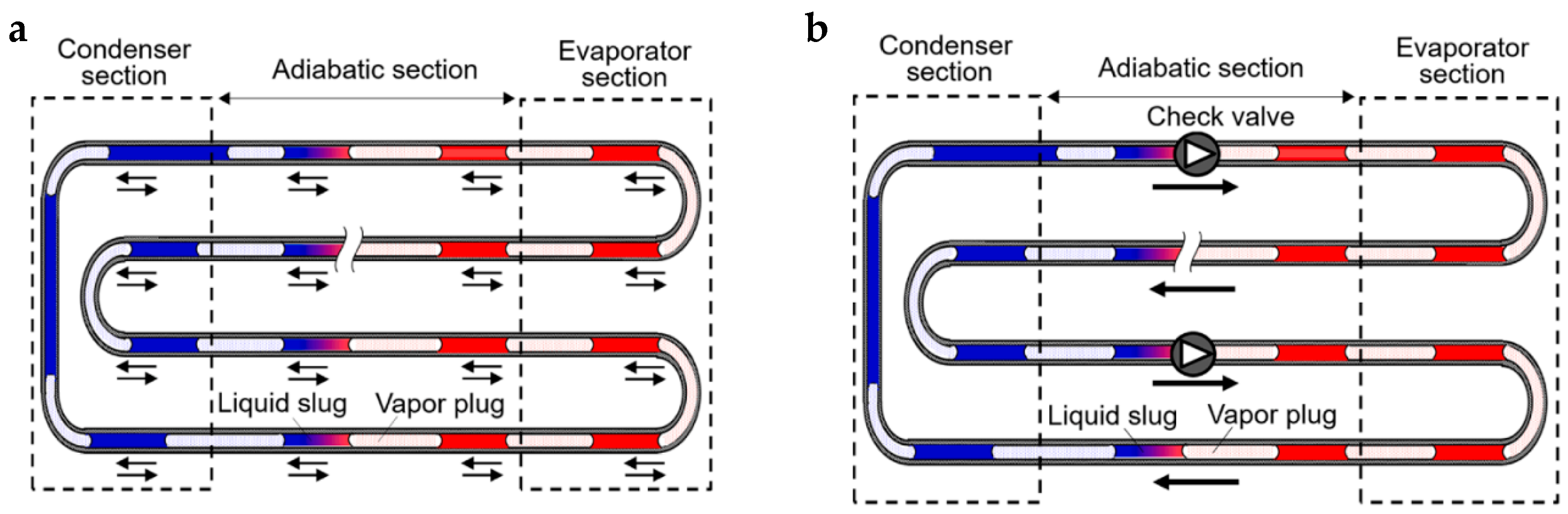
2.3. PHP
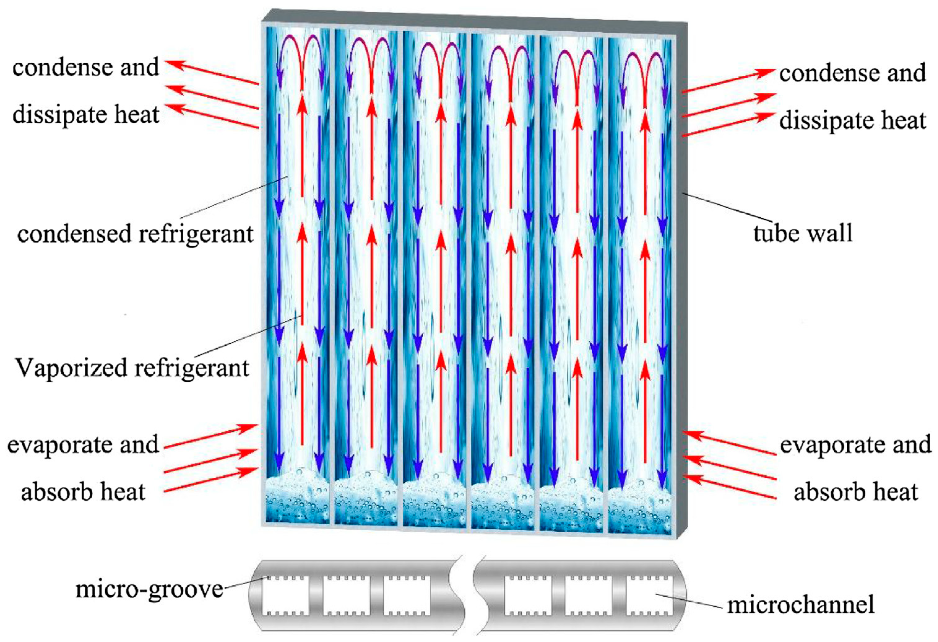
2.4. FHP
3. Overview and Discussion of the Application of HP Applied in the ACS
3.1. Natural Cooling System Integrated with HP
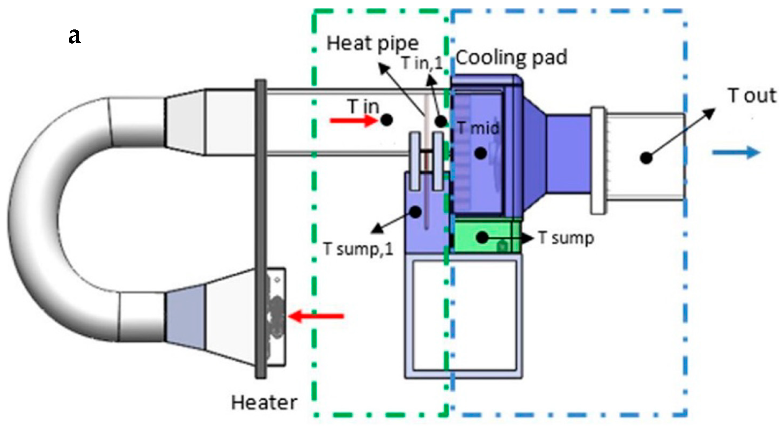
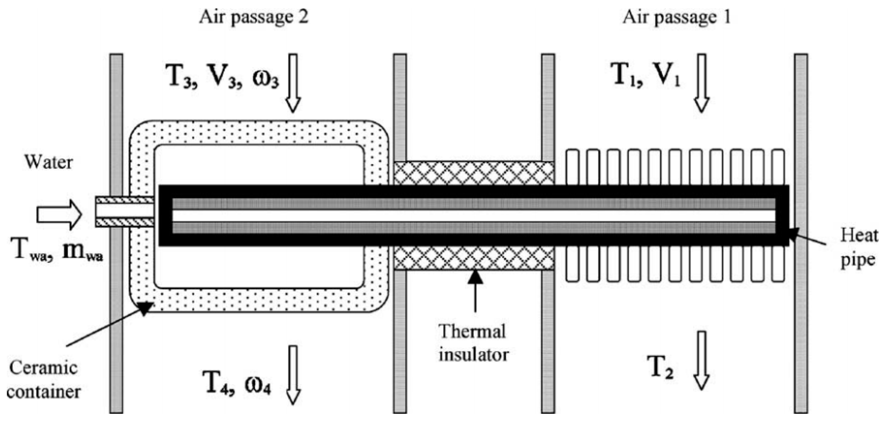
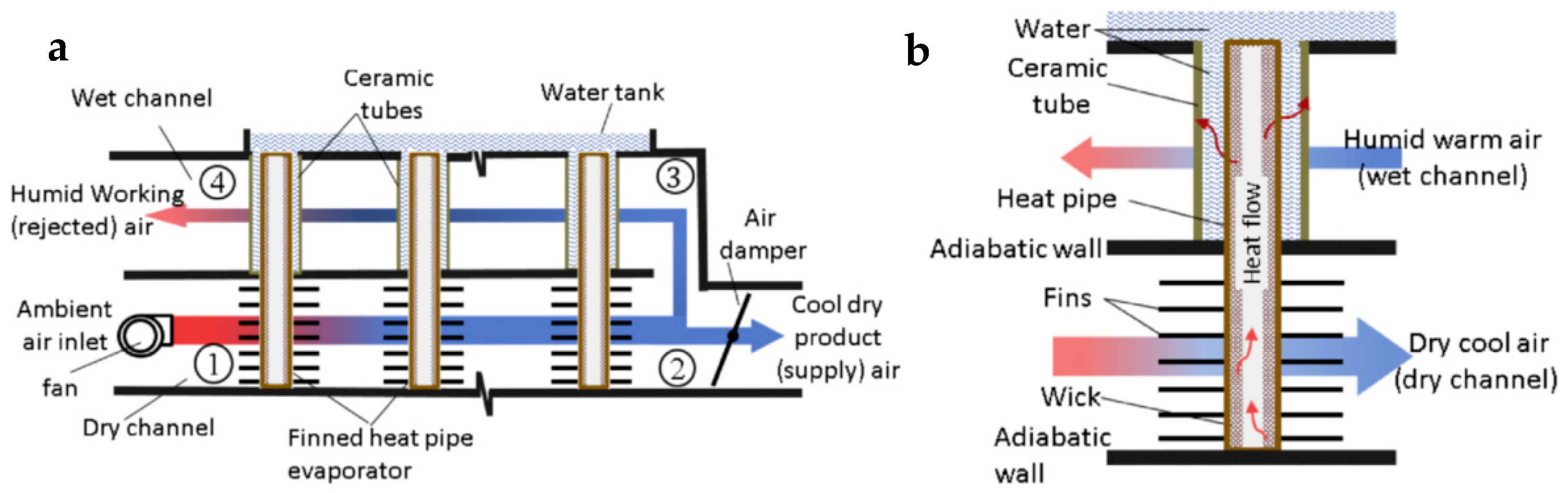
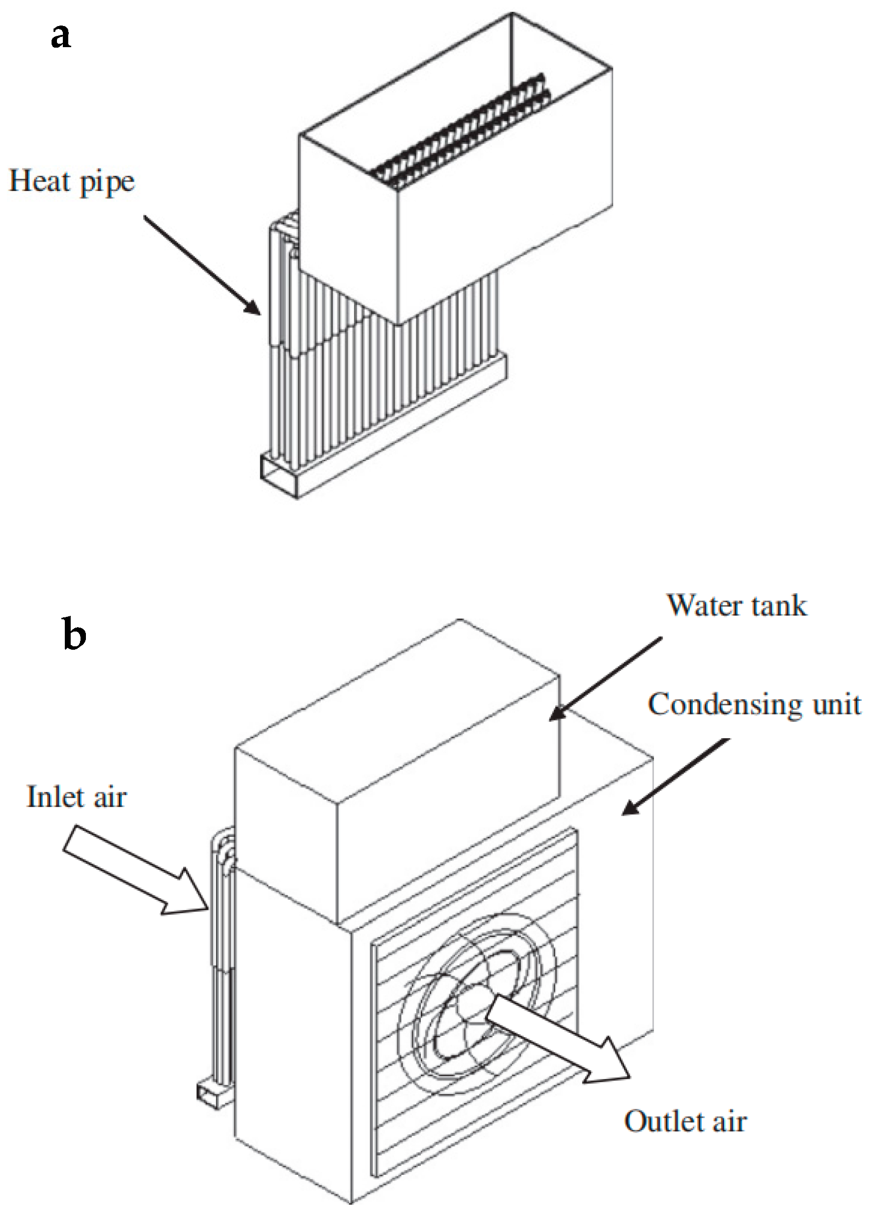
3.2. Evaporative Cooling System Integrated with HP
3.3. Split Air Conditioner Integrated with HP
3.4. Centralized ACSs Integrated with HP
3.4.1. Dehumidification Based on the HPHE
3.4.2. Exhaust Heat Recovery System Based on HPHE
3.4.3. Dehumidification and Heat Recovery Systems Based on the Multi-HPHE
3.5. Cooling Radiator Integrated with HP
4. Conclusions and Future Works
Author Contributions
Funding
Data Availability Statement
Conflicts of Interest
References
- IEA. Energy Technology Perspective 2017; Catalysing Energy Technology Transformations: Paris, France, 2017. [Google Scholar]
- Casals, X.G. Analysis of building energy regulation and certification in Europe: Their role, limitations and differences. Energy Build. 2006, 38, 381–392. [Google Scholar] [CrossRef]
- Liu, Z.; Liu, Y.; He, B.-J.; Xu, W.; Jin, G.; Zhang, X. Application and suitability analysis of the key technologies in nearly zero energy buildings in China. Renew. Sustain. Energy Rev. 2019, 101, 329–345. [Google Scholar] [CrossRef]
- Al-Shargabi, A.A.; Almhafdy, A.; Ibrahim, D.M.; Alghieth, M.; Chiclana, F. Buildings’ energy consumption prediction models based on buildings’ characteristics: Research trends, taxonomy, and performance measures. J. Build. Eng. 2022, 54, 104577. [Google Scholar] [CrossRef]
- Yuan, T.; Ding, Y.; Zhang, Q.; Zhu, N.; Yang, K.; He, Q. Thermodynamic and economic analysis for ground-source heat pump system coupled with borehole free cooling. Energy Build. 2017, 155, 185–197. [Google Scholar] [CrossRef]
- Solano, J.; Caamaño-Martín, E.; Olivieri, L.; Almeida-Galárraga, D. HVAC systems and thermal comfort in buildings climate control: An experimental case study. Energy Rep. 2021, 7, 269–277. [Google Scholar] [CrossRef]
- Zhang, Z.; Zhang, Y.; Khan, A. Thermal comfort of people in a super high-rise building with central air-conditioning system in the hot-humid area of China. Energy Build. 2020, 209, 109727. [Google Scholar] [CrossRef]
- Kokogiannakis, G.; Daly, D.; McDowell, C.; Roth, J.; Tibbs, M.; Cooper, P. In-situ comparison between the energy performance of an in-slab gas heating system and a split system air conditioning in classrooms. Energy Build. 2023, 279, 112713. [Google Scholar] [CrossRef]
- Yang, H.; Pei, N.; Liu, L.; Fan, M.; Qin, Y. Experimental study on the effect of condensate water on the performance of split air conditioning system. Energy Rep. 2021, 7, 840–851. [Google Scholar] [CrossRef]
- Yau, Y.; Pean, H. The performance study of a split type air conditioning system in the tropics, as affected by weather. Energy Build. 2014, 72, 1–7. [Google Scholar] [CrossRef]
- Deng, X.; Shen, Y.; Yang, S.; Feng, J.; Wang, S.; Li, D.; Li, Y. Feasibility of condensate water recycle of split air handling unit in Chinese University buildings. Energy Built Environ. 2022, 5, 309–315. [Google Scholar] [CrossRef]
- Li, X.; Zhang, C.; Zhao, T.; Han, Z. Adaptive predictive control method for improving control stability of air-conditioning terminal in public buildings. Energy Build. 2021, 249, 111261. [Google Scholar] [CrossRef]
- Zhou, F.; Liu, Y.; Zhao, Y.; Ma, G. Dehumidifying characteristics of air conditioner with reheating coil under mild and humid conditions. Appl. Therm. Eng. 2021, 196, 117338. [Google Scholar] [CrossRef]
- Shafieian, A.; Khiadani, M. A multipurpose desalination, cooling, and air-conditioning system powered by waste heat recovery from diesel exhaust fumes and cooling water. Case Stud. Therm. Eng. 2020, 21, 100702. [Google Scholar] [CrossRef]
- Filipsson, P.; Trüschel, A.; Gräslund, J.; Dalenbäck, J.-O. Performance evaluation of a direct ground-coupled self-regulating active chilled beam system. Energy Build. 2020, 209, 109691. [Google Scholar] [CrossRef]
- Arumugam, P.; Ramalingam, V.; Vellaichamy, P. Effective PCM, insulation, natural and/or night ventilation techniques to enhance the thermal performance of buildings located in various climates—A review. Energy Build. 2022, 258, 111840. [Google Scholar] [CrossRef]
- Vidrih, B.; Arkar, C.; Medved, S. Generalized model-based predictive weather control for the control of free cooling by enhanced night-time ventilation. Appl. Energy 2016, 168, 482–492. [Google Scholar] [CrossRef]
- Aili, A.; Zhao, D.; Lu, J.; Zhai, Y.; Yin, X.; Tan, G.; Yang, R. A kW-scale, 24-hour continuously operational, radiative sky cooling system: Experimental demonstration and predictive modeling. Energy Convers. Manag. 2019, 186, 586–596. [Google Scholar] [CrossRef]
- Jia, L.; Lu, L.; Chen, J.; Han, J. A novel radiative sky cooling-assisted ground-coupled heat exchanger system to improve thermal and energy efficiency for buildings in hot and humid regions. Appl. Energy 2022, 322, 119422. [Google Scholar] [CrossRef]
- Gratia, E.; Bruyere, I.; De Herde, A. How to use natural ventilation to cool narrow office buildings. Build. Environ. 2004, 39, 1157–1170. [Google Scholar] [CrossRef]
- Nwaji, G.; Okoronkwo, C.; Ogueke, N.; Anyanwu, E. Hybrid solar water heating/nocturnal radiation cooling system I: A review of the progress, prospects and challenges. Energy Build. 2019, 198, 412–430. [Google Scholar] [CrossRef]
- Delgado, M.G.; Ramos, J.S.; Domínguez, S. Using the sky as heat sink: Climatic applicability of night-sky based natural cooling techniques in Europe. Energy Convers. Manag. 2020, 225, 113424. [Google Scholar] [CrossRef]
- Shuxue, X.; Jianhui, N.; Hongxia, M.; Guoyuan, M. Cooling and dehumidification performance study of a new air conditioning system with double evaporation temperature. Energy Build. 2023, 295, 113294. [Google Scholar] [CrossRef]
- Ahmadzadehtalatapeh, M.; Yau, Y. The application of heat pipe heat exchangers to improve the air quality and reduce the energy consumption of the air conditioning system in a hospital ward—A full year model simulation. Energy Build. 2011, 43, 2344–2355. [Google Scholar] [CrossRef]
- Korpela, T.; Kuosa, M.; Sarvelainen, H.; Tuliniemi, E.; Kiviranta, P.; Tallinen, K.; Koponen, H.K. Waste heat recovery potential in residential apartment buildings in Finland’s Kymenlaakso region by using mechanical exhaust air ventilation and heat pumps. Int. J. Thermofluids 2022, 13, 100127. [Google Scholar] [CrossRef]
- Hesaraki, A.; Huda, N. A comparative review on the application of radiant low-temperature heating and high-temperature cooling for energy, thermal comfort, indoor air quality, design and control. Sustain. Energy Technol. Assess. 2022, 49, 101661. [Google Scholar] [CrossRef]
- Liao, W.; Luo, Y.; Peng, J.; Wang, D.; Yuan, C.; Yin, R.; Li, N. Experimental study on energy consumption and thermal environment of radiant ceiling heating system for different types of rooms. Energy 2022, 244, 122555. [Google Scholar] [CrossRef]
- González-Cruz, E.M.; Krüger, E.L. Experimental study on a low energy radiant-capacitive heating and cooling system. Energy Build. 2022, 255, 111674. [Google Scholar] [CrossRef]
- Chen, Y.; Wang, D.; Liu, Y.; Wang, Y.; Liu, Y. Experimental investigation on the thermal performance of an enhanced convection-radiant heating wall panel with orifices. Int. J. Therm. Sci. 2022, 181, 107704. [Google Scholar] [CrossRef]
- Anand, R.; Jawahar, C.; Solomon, A.B.; Bellos, E. A review of experimental studies on cylindrical two-phase closed thermosyphon using refrigerant for low-temperature applications. Int. J. Refrig. 2020, 120, 296–313. [Google Scholar] [CrossRef]
- Qian, N.; Marengo, M.; Chen, J.; Fu, Y.; Zhang, J.; Xu, J. Heat transfer and temperature characteristics of single-loop oscillating heat pipe under axial-rotation conditions. Int. J. Heat Mass Transf. 2022, 197, 123308. [Google Scholar] [CrossRef]
- Xu, Q.; Yang, G.; Wang, C.; Liu, Z.; Zhang, X.; Li, Z.; Lohani, S.P.; Zhao, Y.; Xiong, Y.; Ding, Y. Experimental study on the reinforcement of a gravity heat pipe based on a latent thermal functionally fluid. Energy 2023, 278, 127782. [Google Scholar] [CrossRef]
- Maydanik, Y.F. Loop heat pipes. Appl. Therm. Eng. 2005, 25, 635–657. [Google Scholar] [CrossRef]
- Zhao, Y.H.; Zhang, K.R.; Diao, Y.H. Heat Pipe with Micro-Pore Tubes Array and Making Method Thereof and Heat Exchanging System. U.S. Patent, US20110203777 A1, 25 August 2011. [Google Scholar]
- Jouhara, H.; Bertrand, D.; Axcell, B.; Montorsi, L.; Venturelli, M.; Almahmoud, S.; Milani, M.; Ahmad, L.; Chauhan, A. Investigation on a full-scale heat pipe heat exchanger in the ceramics industry for waste heat recovery. Energy 2021, 223, 120037. [Google Scholar] [CrossRef]
- Deng, Z.; Zheng, Y.; Liu, X.; Zhu, B.; Chen, Y. Experimental study on thermal performance of an anti-gravity pulsating heat pipe and its application on heat recovery utilization. Appl. Therm. Eng. 2017, 125, 1368–1378. [Google Scholar] [CrossRef]
- Liu, X.; Han, X.; Wang, Z.; Hao, G.; Zhang, Z.; Chen, Y. Application of an anti-gravity oscillating heat pipe on enhancement of waste heat recovery. Energy Convers. Manag. 2020, 205, 112404. [Google Scholar] [CrossRef]
- Abdelkareem, M.A.; Maghrabie, H.M.; Sayed, E.T.; Kais, E.-C.A.; Abo-Khalil, A.G.; Al Radi, M.; Baroutaji, A.; Olabi, A. Heat pipe-based waste heat recovery systems: Background and applications. Therm. Sci. Eng. Prog. 2022, 29, 101221. [Google Scholar] [CrossRef]
- Veerasamy, A.; Balakrishnan, K.; Razack, S.A. Performance of heat pipe with nanorefrigerant in electronic cooling applications. Mater. Today Proc. 2022, 65, 375–379. [Google Scholar] [CrossRef]
- Chen, A.; Jiang, F.; Dong, J.; Chen, J.; Zhu, Y. Design, fabrication and thermal performance of a novel ultra-thin loop heat pipe with printed wick structure for mobile electronics cooling. Appl. Therm. Eng. 2022, 200, 117683. [Google Scholar] [CrossRef]
- Phan, N.; Nagano, H. Novel hybrid structures to improve performance of miniature flat evaporator loop heat pipes for electronics cooling. Int. J. Heat Mass Transf. 2022, 195, 123187. [Google Scholar] [CrossRef]
- Gudeta, M.S.; Atnaw, S.M.; Shibeshi, M.; Gardie, E. Performance analysis of solar water heater system with heat pipe evacuated tube collector on Moha soft drink industries in Ethiopia. Case Stud. Therm. Eng. 2022, 36, 102211. [Google Scholar] [CrossRef]
- Li, H.; Liu, H.; Li, M. Review on heat pipe based solar collectors: Classifications, performance evaluation and optimization, and effectiveness improvements. Energy 2022, 244, 122582. [Google Scholar] [CrossRef]
- Tamuli, B.R.; Nath, S.; Bhanja, D. Performance enhancement of a dual heat pipe array based evacuated tube solar water heater for north eastern India climatic condition: A numerical approach. Appl. Therm. Eng. 2022, 213, 118597. [Google Scholar] [CrossRef]
- Wang, Z.; Diao, Y.; Liang, L.; Zhao, Y.; Zhu, T.; Bai, F. Experimental study on an integrated collector storage solar air heater based on flat micro-heat pipe arrays. Energy Build. 2017, 152, 615–628. [Google Scholar] [CrossRef]
- Li, H.; Sun, Y. Operational performance study on a photovoltaic loop heat pipe/solar assisted heat pump water heating system. Energy Build. 2018, 158, 861–872. [Google Scholar] [CrossRef]
- Wang, G.; Yang, Y.; Yu, W.; Wang, T.; Zhu, T. Performance of an air-cooled photovoltaic/thermal system using micro heat pipe array. Appl. Therm. Eng. 2022, 217, 119184. [Google Scholar] [CrossRef]
- Song, Z.; Ji, J.; Li, Z. Comparison analyses of three photovoltaic solar-assisted heat pumps based on different concentrators. Energy Build. 2021, 251, 111348. [Google Scholar] [CrossRef]
- Zhao, Y.; Fan, Y.; Li, W.; Li, Y.; Ge, M.; Xie, L. Experimental investigation of heat pipe thermoelectric generator. Energy Convers. Manag. 2022, 252, 115123. [Google Scholar] [CrossRef]
- Sun, X.; Ling, L.; Liao, S.; Chu, Y.; Fan, S.; Mo, Y. A thermoelectric cooler coupled with a gravity-assisted heat pipe: An analysis from heat pipe perspective. Energy Convers. Manag. 2018, 155, 230–242. [Google Scholar] [CrossRef]
- Liu, Z.; Cheng, K.; Wang, Z.; Wang, Y.; Ha, C.; Qin, J. Performance analysis of the heat pipe-based thermoelectric generator (HP-TEG) energy system using in-situ resource for heat storage applied to the early-period lunar base. Appl. Therm. Eng. 2023, 218, 119303. [Google Scholar] [CrossRef]
- Wang, X.; Wen, Q.; Yang, J.; Xiang, J.; Wang, Z.; Weng, C.; Chen, F.; Zheng, S. A review on data centre cooling system using heat pipe technology. Sustain. Comput. Informatics Syst. 2022, 35, 100774. [Google Scholar] [CrossRef]
- Sun, Y.; Wang, T.; Yang, L.; Hu, L.; Zeng, X. Research of an integrated cooling system consisted of compression refrigeration and pump-driven heat pipe for data centers. Energy Build. 2019, 187, 16–23. [Google Scholar] [CrossRef]
- He, Z.; Xi, H.; Ding, T.; Wang, J.; Li, Z. Energy efficiency optimization of an integrated heat pipe cooling system in data center based on genetic algorithm. Appl. Therm. Eng. 2021, 182, 115800. [Google Scholar] [CrossRef]
- Chaudhry, H.N.; Hughes, B.R.; Ghani, S.A. A review of heat pipe systems for heat recovery and renewable energy applications. Renew. Sustain. Energy Rev. 2012, 16, 2249–2259. [Google Scholar] [CrossRef]
- Eidan, A.A.; Alshukri, M.J.; Al-Fahham, M.; AlSahlani, A.; Abdulridha, D.M. Optimizing the performance of the air conditioning system using an innovative heat pipe heat exchanger. Case Stud. Therm. Eng. 2021, 26, 101075. [Google Scholar] [CrossRef]
- Guo, Z.; Shao, J.; Li, X.; Liu, R.; Wang, W.; Tian, X. Application of pump-assisted separate heat pipe on dehumidifying enhancement in air conditioning system. Appl. Therm. Eng. 2016, 98, 374–379. [Google Scholar] [CrossRef]
- Wang, Y.; Wang, X.; Wang, J.; Liu, Y.; Chen, J. Heat transfer performance of a two-phase closed thermosyphon with different inclination angles based on the core-tube monitoring. Case Stud. Therm. Eng. 2023, 42, 102738. [Google Scholar] [CrossRef]
- Kafeel, K.; Turan, A. Simulation of the response of a thermosyphon under pulsed heat input conditions. Int. J. Therm. Sci. 2014, 80, 33–40. [Google Scholar] [CrossRef]
- Jose, J.; Hotta, T.K. A comprehensive review of heat pipe: Its types, incorporation techniques, methods of analysis and applications. Therm. Sci. Eng. Prog. 2023, 42, 101860. [Google Scholar] [CrossRef]
- Zhang, J.; Song, G.; Qiu, Z.; Li, H. Thermal analysis and effects study of evaporator exit vapor quality in a separate heat pipe. Appl. Therm. Eng. 2020, 181, 115716. [Google Scholar] [CrossRef]
- Deng, W.; Wang, X.; Ye, Q.; Zhao, H.; Xu, J. Development of the double two-phase thermosyphon loops used in low temperature Stirling refrigerator. Int. J. Refrig. 2023, 155, 173–183. [Google Scholar] [CrossRef]
- Li, C.; Liu, Z.; Zhang, X. Steady-state operating characteristics analysis of loop heat pipes with flat-plate evaporator. Therm. Sci. Eng. Prog. 2022, 28, 101070. [Google Scholar] [CrossRef]
- Bai, L.; Guo, J.; Lin, G.; He, J.; Wen, D. Steady-state modeling and analysis of a loop heat pipe under gravity-assisted operation. Appl. Therm. Eng. 2015, 83, 88–97. [Google Scholar] [CrossRef]
- Akachi, H. Structure of a Heat Pipe. U.S. Patent 4,921,041, 1 May 1990. [Google Scholar]
- Feng, C.; Wan, Z.; Mo, H.; Tang, H.; Lu, L.; Tang, Y. Heat transfer characteristics of a novel closed-loop pulsating heat pipe with a check valve. Appl. Therm. Eng. 2018, 141, 558–564. [Google Scholar] [CrossRef]
- Ando, M.; Okamoto, A.; Nagai, H. Start-up and heat transfer characteristics of oscillating heat pipe with different check valve layouts. Appl. Therm. Eng. 2021, 196, 117286. [Google Scholar] [CrossRef]
- Sun, H.; Wu, Y.; Lin, B.; Duan, M.; Lin, Z.; Li, H. Experimental investigation on the thermal performance of a novel radiant heating and cooling terminal integrated with a flat heat pipe. Energy Build. 2020, 208, 109646. [Google Scholar] [CrossRef]
- Saw, L.; Yew, M.; Chong, W.; Poon, H.; Liew, W.; Yeo, W. Development of the closed loop pulsating heat pipe cool roof system for residential buildings. Case Stud. Therm. Eng. 2021, 28, 101487. [Google Scholar] [CrossRef]
- Li, Z.; Zhang, Z. Dynamic heat transfer characteristics of wall implanted with heat pipes in summer. Energy Build. 2018, 170, 40–46. [Google Scholar] [CrossRef]
- Turnpenny, J.; Etheridge, D.; Reay, D. Novel ventilation cooling system for reducing air conditioning in buildings.: Part I: Testing and theoretical modelling. Appl. Therm. Eng. 2000, 20, 1019–1037. [Google Scholar] [CrossRef]
- Singh, R.; Mochizuki, M.; Mashiko, K.; Nguyen, T. Heat pipe based cold energy storage systems for datacenter energy conservation. Energy 2011, 36, 2802–2811. [Google Scholar] [CrossRef]
- Yan, C.; Shi, W.; Li, X.; Wang, S. A seasonal cold storage system based on separate type heat pipe for sustainable building cooling. Renew. Energy 2016, 85, 880–889. [Google Scholar] [CrossRef]
- Chotivisarut, N.; Nuntaphan, A.; Kiatsiriroat, T. Seasonal cooling load reduction of building by thermosyphon heat pipe radiator in different climate areas. Renew. Energy 2012, 38, 188–194. [Google Scholar] [CrossRef]
- Chotivisarut, N.; Kiatsiriroat, T. Cooling load reduction of building by seasonal nocturnal cooling water from thermosyphon heat pipe radiator. Int. J. Energy Res. 2009, 33, 1089–1098. [Google Scholar] [CrossRef]
- He, W.; Yu, C.; Yang, J.; Yu, B.; Hu, Z.; Shen, D.; Liu, X.; Qin, M.; Chen, H. Experimental study on the performance of a novel RC-PCM-wall. Energy Build. 2019, 199, 297–310. [Google Scholar] [CrossRef]
- Yu, C.; Shen, D.; He, W.; Hu, Z.; Zhang, S.; Chu, W. Parametric analysis of the phase change material wall combining with micro-channel heat pipe and sky radiative cooling technology. Renew. Energy 2021, 178, 1057–1069. [Google Scholar] [CrossRef]
- Yu, C.; Shen, D.; Wang, W.; Song, X.; Xin, J.; Cai, L.; Tu, J. Numerical study on the thermal performance of phase change materials wall by radiative cooling. Appl. Therm. Eng. 2022, 215, 119013. [Google Scholar] [CrossRef]
- Shen, D.; Yu, C.; Wang, W. Investigation on the thermal performance of the novel phase change materials wall with radiative cooling. Appl. Therm. Eng. 2020, 176, 115479. [Google Scholar] [CrossRef]
- Yan, T.; Li, J.; Gao, J.; Xu, X.; Yu, J. Model validation and application of the coupled system of pipe-encapsulated PCM wall and nocturnal sky radiator. Appl. Therm. Eng. 2021, 194, 117057. [Google Scholar] [CrossRef]
- Yan, T.; Zhou, X.; Xu, X.; Yu, J.; Li, X. Parametric analysis on performances of the pipe-encapsulated PCM (PenPCM) wall system coupled with gravity heat-pipe and nocturnal radiant cooler. Renew. Energy 2022, 196, 161–180. [Google Scholar] [CrossRef]
- Yan, T.; Luo, Y.; Xu, T.; Wu, H.; Xu, X.; Li, J. Experimental study of the coupled wall system of pipe-encapsulated PCM wall and nocturnal sky radiator for self-activated heat removal. Energy Build. 2021, 241, 110964. [Google Scholar] [CrossRef]
- Yan, T.; Sun, Z.; Gao, J.; Xu, X.; Yu, J.; Gang, W. Simulation study of a pipe-encapsulated PCM wall system with self-activated heat removal by nocturnal sky radiation. Renew. Energy 2020, 146, 1451–1464. [Google Scholar] [CrossRef]
- Yan, T.; Gao, J.; Xu, X.; Xu, T.; Ling, Z.; Yu, J. Dynamic simplified PCM models for the pipe-encapsulated PCM wall system for self-activated heat removal. Int. J. Therm. Sci. 2019, 144, 27–41. [Google Scholar] [CrossRef]
- Amer, O.; Boukhanouf, R.; Ibrahim, H.G. A review of evaporative cooling technologies. Int. J. Environ. Sci. Dev. 2015, 6, 111–117. [Google Scholar] [CrossRef]
- Abdullah, S.; Zubir, M.N.B.M.; Bin Muhamad, M.R.; Newaz, K.M.S.; Öztop, H.F.; Alam, S.; Shaikh, K. Technological development of evaporative cooling systems and its integration with air dehumidification processes: A review. Energy Build. 2023, 283, 112805. [Google Scholar] [CrossRef]
- Fikri, B.; Putra NS, D.; Winarta, A.; AAbdullah, N.; Ariantara, B. Experimental investigation of modified direct evaporative cooler using heat pipe. J. Adv. Res. Fluid Mech. Therm. Sci. 2019, 55, 209–217. [Google Scholar]
- Fikri, B.; Sofia, E.; Putra, N. Experimental analysis of a multistage direct-indirect evaporative cooler using a straight heat pipe. Appl. Therm. Eng. 2020, 171, 115133. [Google Scholar] [CrossRef]
- Riffat, S.; Zhu, J. Mathematical model of indirect evaporative cooler using porous ceramic and heat pipe. Appl. Therm. Eng. 2004, 24, 457–470. [Google Scholar] [CrossRef]
- Riffat, S.; Zhu, J. Experimental Investigation of an Indirect Evaporative Cooler Consisting of a Heat Pipe Embedded in Porous Ceramic. J. Eng. Res. 2004, 1, 46–52. [Google Scholar] [CrossRef]
- Amer, O. A Heat Pipe and Porous Ceramic Based Sub Wet-Bulb Temperature Evaporative Cooler: A Theoretical and Experimental Study. Ph.D. Thesis, University of Nottingham, Nottingham, UK, 2017. [Google Scholar]
- Boukhanouf, R.; Amer, O.; Ibrahim, H.; Calautit, J. Design and performance analysis of a regenerative evaporative cooler for cooling of buildings in arid climates. J. Affect. Disord. 2018, 142, 1–10. [Google Scholar] [CrossRef]
- Rajski, K.; Danielewicz, J.; Brychcy, E. Performance Evaluation of a Gravity-Assisted Heat Pipe-Based Indirect Evaporative Cooler. Energies 2020, 13, 200. [Google Scholar] [CrossRef]
- Alharbi, A.; Almaneea, A.; Boukhanouf, R. Integrated hollow porous ceramic cuboids-finned heat pipes evaporative cooling system: Numerical modelling and experimental validation. Energy Build. 2019, 196, 61–70. [Google Scholar] [CrossRef]
- Naphon, P. On the performance of air conditioner with heat pipe for cooling air in the condenser. Energy Convers. Manag. 2010, 51, 2362–2366. [Google Scholar] [CrossRef]
- Alklaibi, A. Evaluating the possible configurations of incorporating the loop heat pipe into the air-conditioning systems. Int. J. Refrig. 2008, 31, 807–815. [Google Scholar] [CrossRef]
- Nethaji, N.; Mohideen, S.T. Energy conservation studies on a split air conditioner using loop heat pipes. Energy Build. 2017, 155, 215–224. [Google Scholar] [CrossRef]
- Xia, G.; Zhuang, D.; Ding, G. Thermal management solution for enclosed controller used in inverter air conditioner based on heat pipe heat sink. Int. J. Refrig. 2019, 99, 69–79. [Google Scholar] [CrossRef]
- Nakkaew, S.; Chitipalungsri, T.; Ahn, H.S.; Jerng, D.-W.; Asirvatham, L.G.; Dalkılıç, A.S.; Mahian, O.; Wongwises, S. Application of the heat pipe to enhance the performance of the vapor compression refrigeration system. Case Stud. Therm. Eng. 2019, 15, 100531. [Google Scholar] [CrossRef]
- Wu, X.P.; Johnson, P.; Akbarzadeh, A. Application of heat pipe heat exchangers to humidity control in air-conditioning systems. Appl. Therm. Eng. 1997, 17, 561–568. [Google Scholar] [CrossRef]
- Jouhara, H.; Meskimmon, R. An investigation into the use of water as a working fluid in wraparound loop heat pipe heat exchanger for applications in energy efficient HVAC systems. Energy 2018, 156, 597–605. [Google Scholar] [CrossRef]
- Barrak, A.S.; Saleh, A.A.; Naji, Z.H. An experimental study of using water, methanol, and binary fluids in oscillating heat pipe heat exchanger. Eng. Sci. Technol. Int. J. 2020, 23, 357–364. [Google Scholar] [CrossRef]
- Firouzfar, E.; Soltanieh, M.; Noie, S.H.; Saidi, M.H. Investigation of heat pipe heat exchanger effectiveness and energy saving in air conditioning systems using silver nanofluid. Int. J. Environ. Sci. Technol. 2012, 9, 587–594. [Google Scholar] [CrossRef]
- Yau, Y.H. Application of a heat pipe heat exchanger to dehumidification enhancement in a HVAC system for tropical climates—A baseline performance characteristics study. Int. J. Therm. Sci. 2007, 46, 164–171. [Google Scholar] [CrossRef]
- Yau, Y. Experimental thermal performance study of an inclined heat pipe heat exchanger operating in high humid tropical HVAC systems. Int. J. Refrig. 2007, 30, 1143–1152. [Google Scholar] [CrossRef]
- Yau, Y.; Ahmadzadehtalatapeh, M. A review on the application of horizontal heat pipe heat exchangers in air conditioning systems in the tropics. Appl. Therm. Eng. 2010, 30, 77–84. [Google Scholar] [CrossRef]
- Yau, Y.H.; Ahmadzadehtalatapeh, M. Predicting yearly energy recovery and dehumidification enhancement with a heat pipe heat exchanger using typical meteorological year data in the tropics. J. Mech. Sci. Technol. 2011, 25, 847–853. [Google Scholar] [CrossRef]
- Wan, J.; Zhang, J.; Zhang, W. The effect of heat-pipe air-handling coil on energy consumption in central air-conditioning system. Energy Build. 2007, 39, 1035–1040. [Google Scholar] [CrossRef]
- Supirattanakul, P.; Rittidech, S.; Bubphachot, B. Application of a closed-loop oscillating heat pipe with check valves (CLOHP/CV) on performance enhancement in air conditioning system. Energy Build. 2011, 43, 1531–1535. [Google Scholar] [CrossRef]
- Kusumah, A.S.; Hakim, I.I.; Sukarno, R.; Rachman, F.F.; Putra, N. The Application of U-shape Heat Pipe Heat Exchanger to Reduce Relative Humidity for Energy Conservation in Heating, Ventilation, and Air Conditioning (HVAC) Systems. Int. J. Technol. 2019, 10, 1202–1210. [Google Scholar] [CrossRef]
- Hakim, I.I.; Sukarno, R.; Putra, N. Utilization of U-shaped finned heat pipe heat exchanger in energy-efficient HVAC systems. Therm. Sci. Eng. Prog. 2021, 25, 100984. [Google Scholar] [CrossRef]
- Jouhara, H.; Meskimmon, R. Experimental investigation of wraparound loop heat pipe heat exchanger used in energy efficient air handling units. Energy 2010, 35, 4592–4599. [Google Scholar] [CrossRef]
- Li, M.; Ju, Y. Experimental investigation on the thermal performance of wraparound loop heat pipe heat exchanger for heat recovery in air handling units. Heat Transf. Res. 2017, 48, 1313–1326. [Google Scholar] [CrossRef]
- Sarkar, M. On Climatic Control of Wrap-Around Heat Pipe (WAHP) Enhanced Dehumidifier in Outdoor Air Systems. Int. J. Air-Cond. Refrig. 2019, 27, 1950013. [Google Scholar] [CrossRef]
- Noie-Baghban, S.H.; Majideian, G.R. Waste heat recovery using heat pipe heat exchanger (HPHE) for surgery rooms in hospitals. Appl. Therm. Eng. 2000, 20, 1271–1282. [Google Scholar] [CrossRef]
- Jadhav, T.; Lele, M. Theoretical energy saving analysis of air conditioning system using heat pipe heat exchanger for Indian climatic zones. Eng. Sci. Technol. Int. J. 2015, 18, 669–673. [Google Scholar] [CrossRef]
- Danielewicz, J.; Sayegh, M.; Śniechowska, B.; Szulgowska-Zgrzywa, M.; Jouhara, H. Experimental and analytical performance investigation of air to air two phase closed thermosyphon based heat exchangers. Energy 2014, 77, 82–87. [Google Scholar] [CrossRef]
- Putra, N.S.D.; Anggoro, T.; Winarta, A. Experimental Study of Heat Pipe Heat Exchanger in Hospital HVAC System for Energy Conservation. Int. J. Adv. Sci. Eng. Inf. Technol. 2017, 7, 871. [Google Scholar] [CrossRef]
- Muhammaddiyah, S.; Winarta, A.; Putra, N. Experimental Study of Heat Pipe Heat Exchanger Multi Fin for Energy Efficiency Effort in Operating Room Air System. Int. J. Technol. 2018, 9, 422–429. [Google Scholar] [CrossRef]
- Sukarno, R.; Putra, N.; Hakim, I.I.; Rachman, F.F.; Mahlia, T.M.I. Utilizing heat pipe heat exchanger to reduce the energy consumption of airborne infection isolation hospital room HVAC system. J. Build. Eng. 2021, 35, 102116. [Google Scholar] [CrossRef]
- Sukarno, R.; Putra, N.; Hakim, I.I.; Rachman, F.F.; Mahlia, T.M.I. Multi-stage heat-pipe heat exchanger for improving energy efficiency of the HVAC system in a hospital operating room 1. Int. J. Low-Carbon Technol. 2021, 16, 259–267. [Google Scholar] [CrossRef]
- Sukarno, R.; Putra, N.; Hakim, I.I. Non-dimensional analysis for heat pipe characteristics in the heat pipe heat exchanger as energy recovery device in the HVAC systems. Therm. Sci. Eng. Prog. 2021, 26, 101122. [Google Scholar] [CrossRef]
- Abd El-Baky, M.A.; Mohamed, M.M. Heat pipe heat exchanger for heat recovery in air conditioning. Appl. Therm. Eng. 2007, 27, 795–801. [Google Scholar] [CrossRef]
- Abdelaziz, G.B.; Abdelbaky, M.; Halim, M.; Omara, M.; Elkhaldy, I.; Abdullah, A.; Omara, Z.; Essa, F.; Ali, A.; Sharshir, S.W.; et al. Energy saving via Heat Pipe Heat Exchanger in air conditioning applications “experimental study and economic analysis”. J. Build. Eng. 2021, 35, 102053. [Google Scholar] [CrossRef]
- Mahajan, G.; Thompson, S.M.; Cho, H. Experimental characterization of an n-pentane oscillating heat pipe for waste heat recovery in ventilation systems. Heliyon 2018, 4, e00922. [Google Scholar] [CrossRef] [PubMed]
- Mahajan, G.; Thompson, S.M.; Cho, H. Energy and cost savings potential of oscillating heat pipes for waste heat recovery ventilation. Energy Rep. 2017, 3, 46–53. [Google Scholar] [CrossRef]
- Yang, H.; Wang, J.; Wang, N.; Yang, F. Experimental study on a pulsating heat pipe heat exchanger for energy saving in air-conditioning system in summer. Energy Build. 2019, 197, 1–6. [Google Scholar] [CrossRef]
- Shen, C.; Zhang, B.; Zhang, D.; Zhang, Y.; Wei, S.; Yang, S. Experimental study on the parallel-flow heat pipe heat exchanger for energy saving in air conditioning. J. Build. Eng. 2023, 75, 106842. [Google Scholar] [CrossRef]
- Liu, D.; Tang, G.-F.; Zhao, F.-Y.; Wang, H.-Q. Modeling and experimental investigation of looped separate heat pipe as waste heat recovery facility. Appl. Therm. Eng. 2006, 26, 2433–2441. [Google Scholar] [CrossRef]
- Xue, L.; Ma, G.; Zhou, F.; Wang, L. Operation characteristics of air–air heat pipe inserted plate heat exchanger for heat recovery. Energy Build. 2019, 185, 66–75. [Google Scholar] [CrossRef]
- Zhou, F.; Duan, W.; Ma, G. Thermal performance of a pump-driven loop heat pipe as an air-to-air energy recovery device. Energy Build. 2017, 151, 206–216. [Google Scholar] [CrossRef]
- Zhou, F.; Duan, W.; Ma, G. Thermal performance of a multi-loop pump-driven heat pipe as an energy recovery ventilator for buildings. Appl. Therm. Eng. 2018, 138, 648–656. [Google Scholar] [CrossRef]
- Liu, S.; Ma, G.; Xu, S.; Jia, X.; Wu, G. Experimental study of ventilation system with heat recovery integrated by pump-driven loop heat pipe and heat pump. J. Build. Eng. 2022, 52, 104404. [Google Scholar] [CrossRef]
- Shuailing, L.; Guoyuan, M.; Xiaoya, J.; Shuxue, X.; Guoqiang, W. Performance of a mechanically-driven loop heat pipe heat recovery system. Appl. Therm. Eng. 2022, 207, 118066. [Google Scholar] [CrossRef]
- Ahmadzadehtalatapeh, M.; Yat Huang, Y. Fully fresh air air-conditioning system equipped with double heat pipe based heat recovery technology. Int. J. Eng. 2013, 26, 51–57. [Google Scholar] [CrossRef]
- Yau, Y. The use of a double heat pipe heat exchanger system for reducing energy consumption of treating ventilation air in an operating theatre—A full year energy consumption model simulation. Energy Build. 2008, 40, 917–925. [Google Scholar] [CrossRef]
- Martinez, F.J.R.; Plasencia, M.A.-G.; Gómez, E.V.; Diez, F.V.; Martin, R.H. Design and experimental study of a mixed energy recovery system, heat pipes and indirect evaporative equipment for air conditioning. Energy Build. 2003, 35, 1021–1030. [Google Scholar] [CrossRef]
- Wang, H.; Zhou, S.; Wei, Z.; Wang, R. A study of secondary heat recovery efficiency of a heat pipe heat exchanger air conditioning system. Energy Build. 2016, 133, 206–216. [Google Scholar] [CrossRef]
- Wu, Y.; Sun, H.; Duan, M.; Lin, B.; Zhao, H. Dehumidification-adjustable cooling of radiant cooling terminals based on a flat heat pipe. J. Affect. Disord. 2021, 194, 107716. [Google Scholar] [CrossRef]
- Zhao, H.; Wu, Y.; Lin, B.; Sun, H. Experimental investigation on the improvement of cooling and dehumidification of a direct-expansion terminal integrated with flat heat pipe. Energy Build. 2022, 260, 111922. [Google Scholar] [CrossRef]


| References | Research Methods | Purpose | HP Types | Installation Direction | HP Working Fluid | Filling Ratio /Volume | Fins | Wick Structure | Core Conclusions |
|---|---|---|---|---|---|---|---|---|---|
| Saw et al. [69] | Experiment | Design an active cool roof system | PHP | Horizontal | Methanol | 80% | N | N | The PHP cool roof system could effectively decrease the attic temperature with a reduction of nearly 12.9%. |
| Li and Zhang [70] | Experiment and simulation | Utilizing air energy and sky radiation energy for cooling | GHP | Vertical | - | 28% | N | N | The heat transfer capacity of the WIHP was 50.7 kW/m2. The average temperature of the inner surface of the north WIHP was about 2 °C lower than that of the conventional wall. |
| Turnpenny et al. [71] | Experiment and simulation | Utilizing air energy for cooling storage | Wicked HP | Horizontal | Methanol | - | Y | Y | The heat transfer rate of the PCM unit was about 40 W during the melt period. |
| Singh et al. [72] | Experiment and simulation | Utilizing air energy for cooling storage | GHP | Vertical | R134a | - | Y | N | The proposed cooling system could handle 60% of the heat load for the datacenter every year. Its payback period was about 3.5 years. |
| Yan et al. [73] | Experiment and simulation | Utilizing air energy for cooling storage | SHP | Vertical | R22 | 100% | Y | N | The proposed system had an annual cooling storage capacity of approximately 31,500 kW and a cooling release capacity of approximately 28,350 kW. The payback period of the seasonal cold storage system was about 8–10 years. |
| Chotivisarut et al. [74,75] | Experiment and simulation | Utilizing sky radiation energy for cooling storage | GHP | Vertical | R134a | 60% | N | N | The proposed system had a great potential in reducing cooling load in low temperature and humidity areas. |
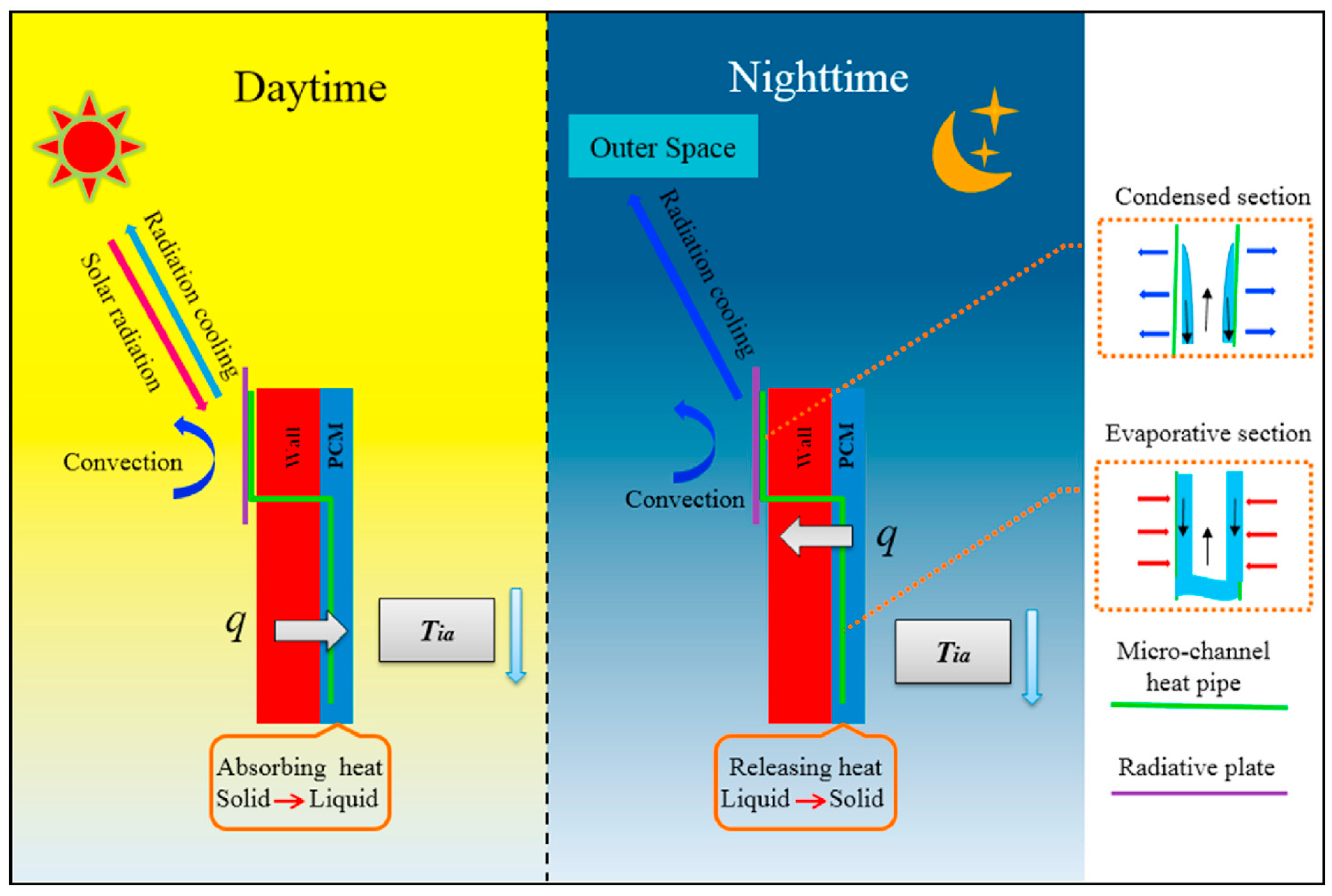
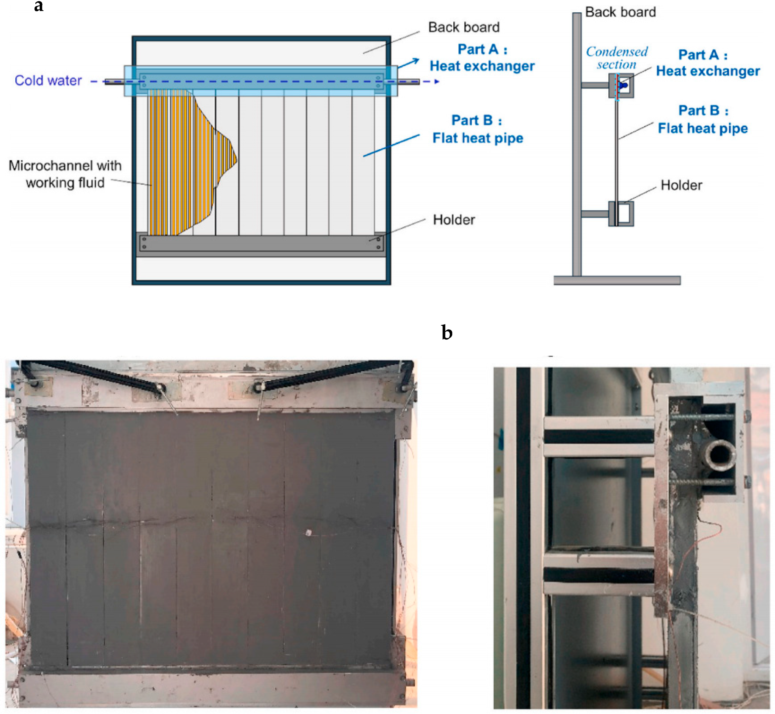
| He et al. [76] | Experiment and simulation | Utilizing sky radiation energy for cooling storage | FHP | Vertical | - | - | N | N | The peak inner surface temperature reduction of the MHP-RC-PCM wall was about 8 °C compared with that of the traditional brick wall. The average time lag of the traditional brick wall, the PCM wall and the MHP-RC-PCM was about 3.1, 4.1 and 4.5 h, respectively. |
| Yu et al. [77,78] | Experiment and simulation | Utilizing sky radiation energy for cooling storage | FHP | Vertical | - | - | N | N | The cooling load and the energy saving efficiency of the MHP-RC-PCM wall were about 22–28% and 18%, respectively, compared with that of the traditional brick wall. |
| Shen et al. [79] | Experiment and simulation | Utilizing sky radiation energy for cooling storage | FHP | Vertical | - | - | N | N | The cooling loads of the south wall were decreased by over 40% under some conditions compared to the traditional brick wall. The low wind speeds favored a lower cooling load, while reducing the emissivity of the radiative plate exhibited the opposite trend. |
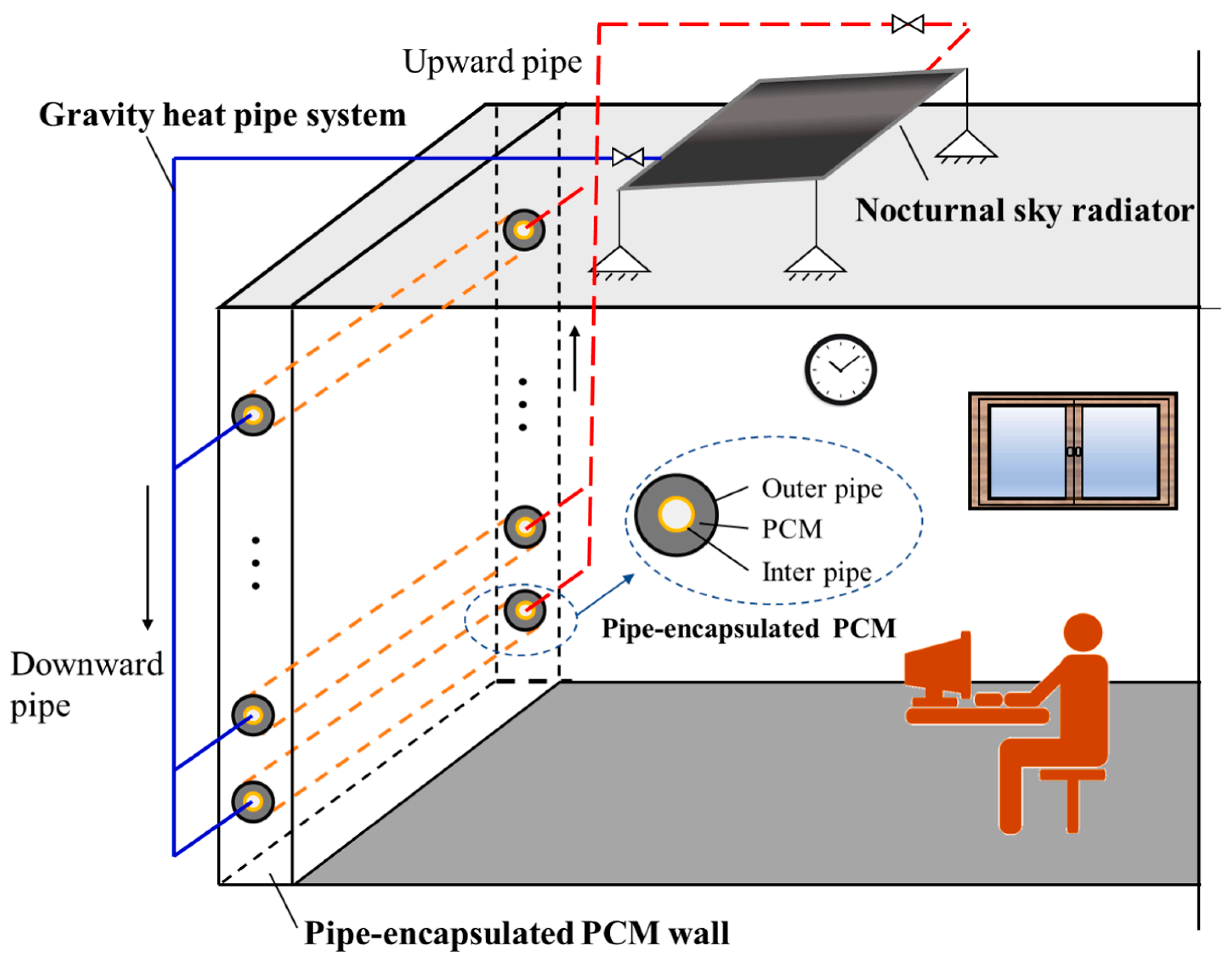
| Yan et al. [80,81,82,83,84] | Experiment and simulation | Utilizing sky radiation energy for cooling storage | GHP | Vertical | R245fa | 20% | N | N | The pipe encapsulated PCM wall system could improve the thermal insulation effect of the wall in the daytime and remove a lot of the indoor heat gain during the nighttime. The cooling loads of buildings with the proposed system in Hong Kong, Wuhan, Beijing, Harbin and Kunming could be reduced by 11.7, 16.1, 21.1, 28.6 and 44.2%, respectively, compared to that of the traditional wall. |
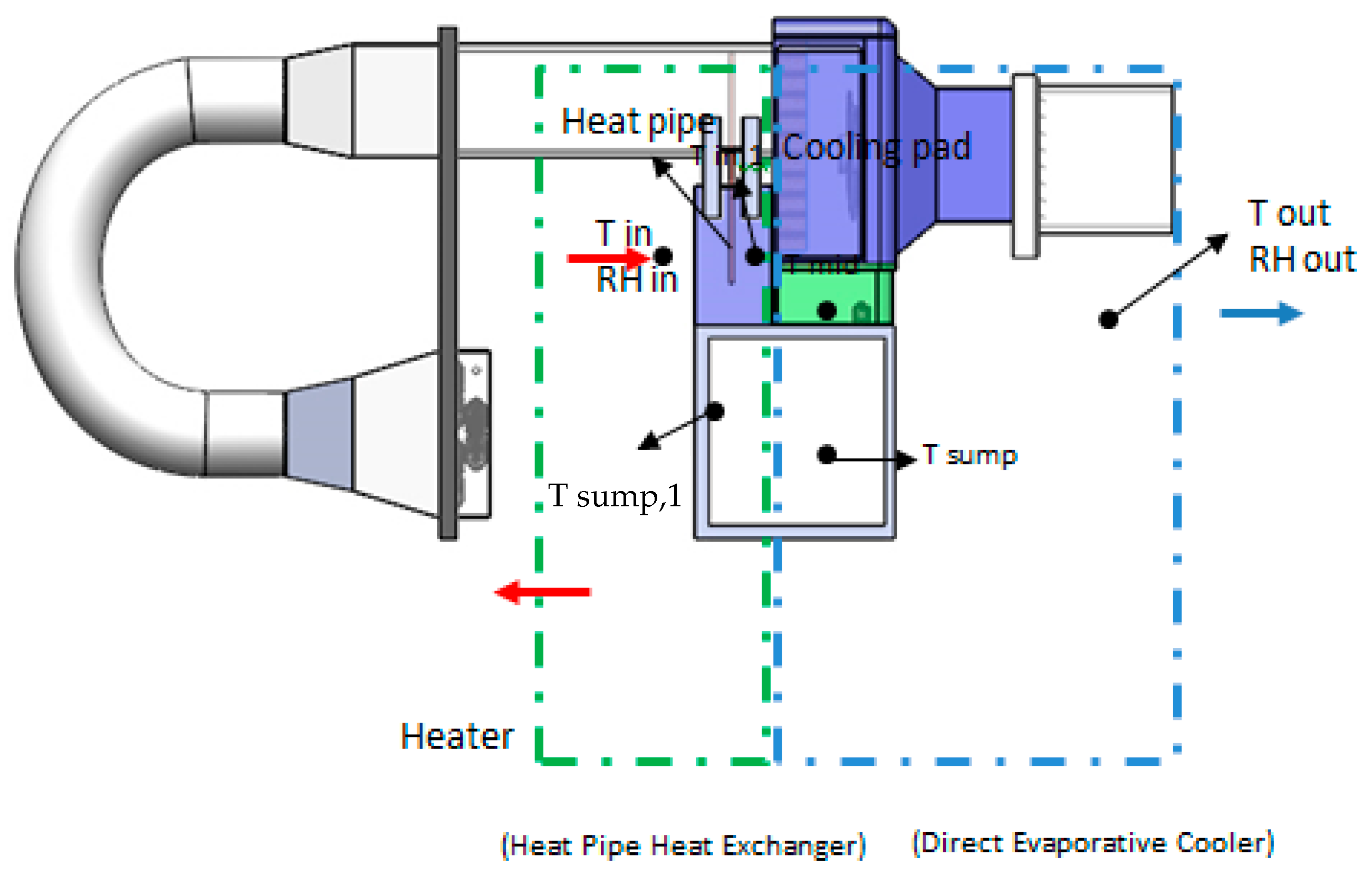
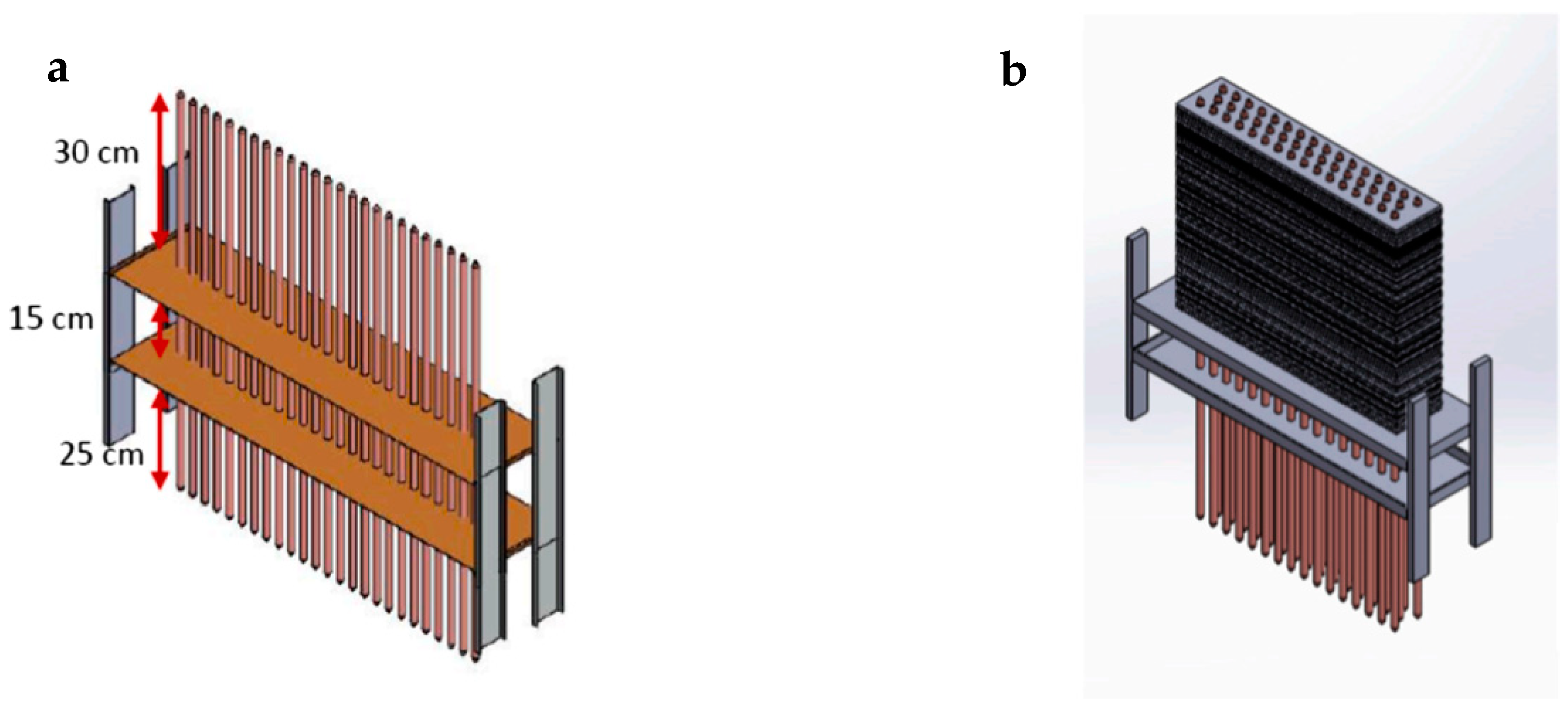
| Fikri et al. [87,88] | Experiment | Enhancing the evaporative cooling performance | GHP | Vertical | Water | 50% | [87]: N [88]: Y | N | The saturation efficiency of the proposed direct-indirect evaporative cooler increased with the increase of the inlet temperature but decreased with the increase of the relative humidity and air velocity. The three-stage combined evaporative cooler provided a suitable relative humidity. |
| Riffat and Zhu [89,90] | Experiment and simulation | Enhancing the evaporative cooling performance | Wicked HP | Horizontal | [89]: - [90]: Distilled water | - | Y | Y | The cooling capacity of the IEC increased as the outdoor air velocity increased. However, it decreased as the outdoor air humidity increased. The indoor air temperature reduction was 3.8 °C per square meter of ceramic surface area for the room equipped with a chilled ceiling using the horizontal IEC. |
| Amer [91] | Experiment and simulation | Enhancing the evaporative cooling performance | Wicked HP | Vertical | Deionised water | - | Y | Y | The cooling capacity of the proposed IEC decreased with the decrease in the inlet air flowrate. In contrast, the wet bulb effectiveness and COP increased as the inlet air flowrate decreased. |
| Boukhanouf et al. [92] | Experiment and simulation | Enhancing the evaporative cooling performance | Wicked HP | Vertical | Deionised water | - | Y | Y | When the inlet air flowrate was 150 m3/s, the wet bulb effectiveness of the proposed system increased from 0.7 to 0.84 with the inlet air temperature increasing from 30 to 40 °C, meanwhile the in- and out-let temperature difference of the supply air increased from about 7.5 to 10.7 °C. An increase in relative humidity would also cause an increase in wet bulb efficiency, but the cooling capacity would be reduced. |
| Rajski et al. [93] | Simulation | Enhancing the evaporative cooling performance | GHP | Vertical | Deionised water | - | Y | N | The wet bulb effectiveness increased as the inlet air temperature and relative humidity increased. The pressure loss increased as the inlet air velocity increased. |
| Alharbi et al. [94] | Experiment and simulation | Enhancing the evaporative cooling performance | Wicked HP | Vertical | Deionised water | - | Y | Y | The cooling capacity increased as the inlet air temperature increased. However, it decreased with an increase in relative humidity. |
| Naphon [95] | Experiment | Enhancing the performance of the SAC | GHP | Vertical | R134a | 50% | N | N | Compared with a conventional SAC, the proposed SAC coupling with the HP cooling device provided the highest COP and energy efficiency ratio (EER) with an increase of 6.4 and 17.5%, respectively. |
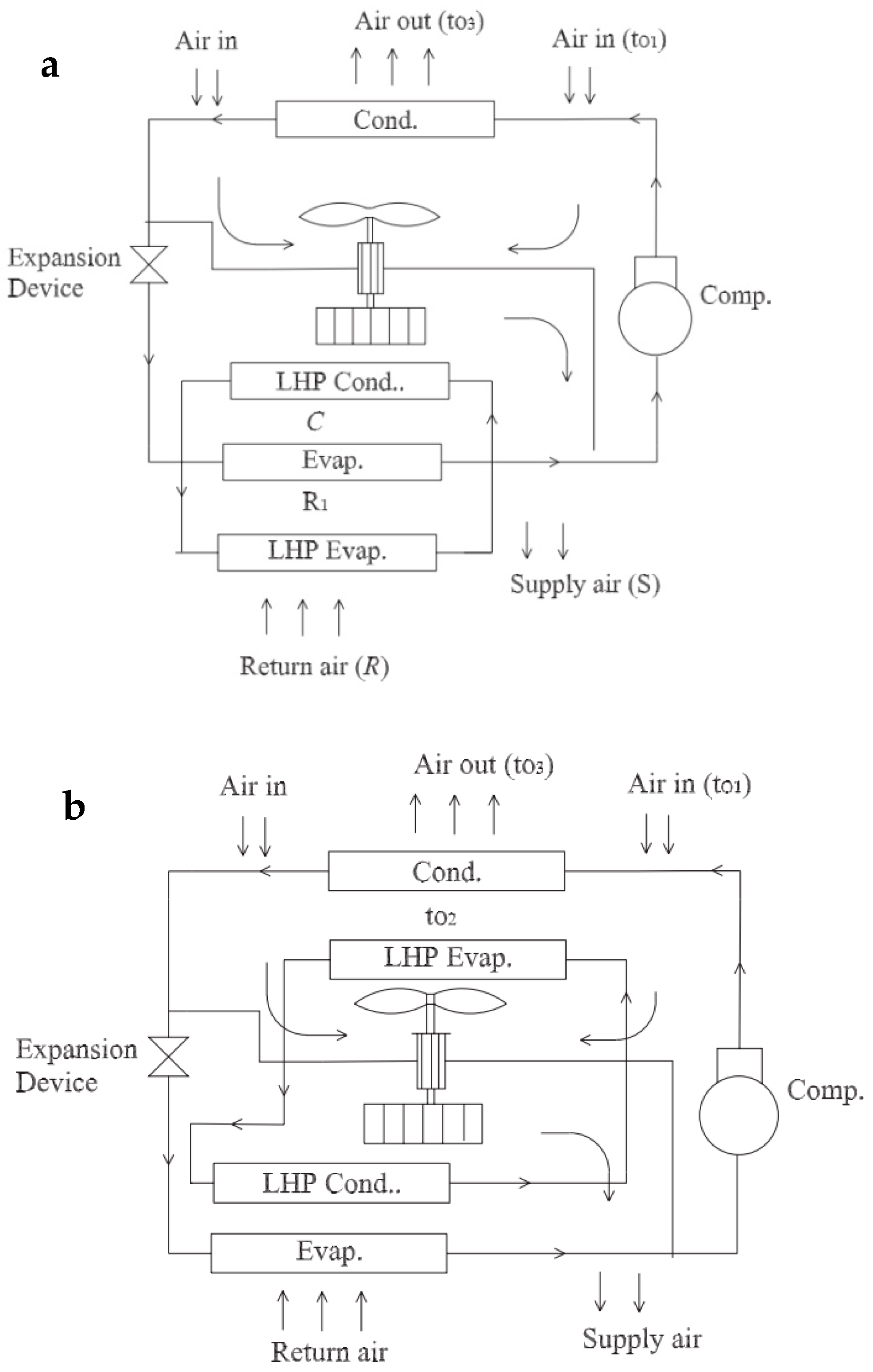
| Alklaibi [95] | Simulation | Enhancing the performance of the SAC | LHP | - | - | - | - | - | Both configurations had the same COP, and the COP could be improved by reducing the compressor energy demand when LHP was used instead of the heating component under a low sensible heat coefficient working condition. |
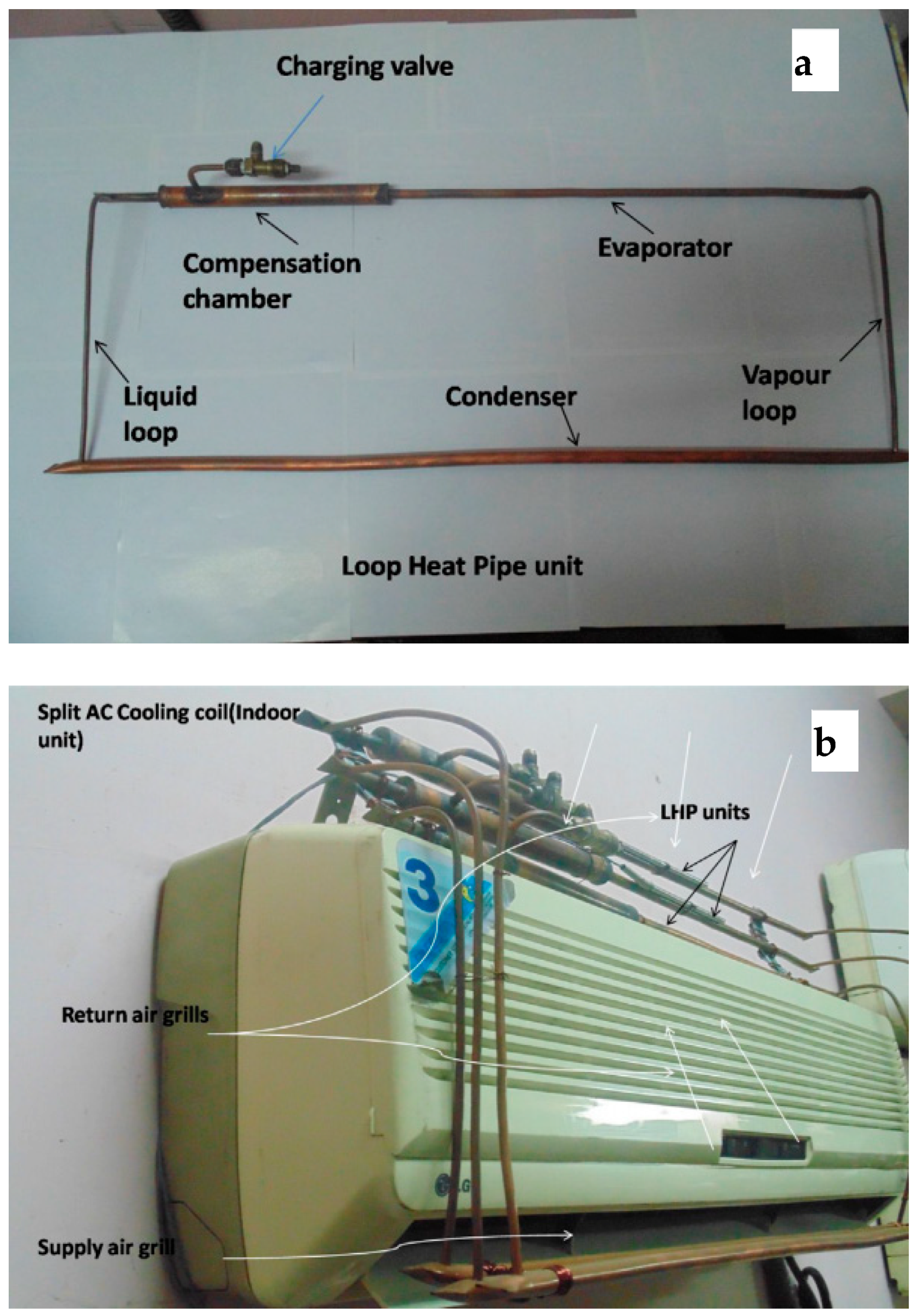
| Nethaji and Tharves Mohideen [97] | Experiment | Enhancing the performance of the SAC | LHP | Horizontal | Ethanol | 51% | N | - | Under the indoor temperature of 22–26 °C and relative humidity of 50%, they found that the COP of the SAC improved by 18–20%. The dehumidification capability was enhanced by 30%. The latent heat recovery was 482 W. |
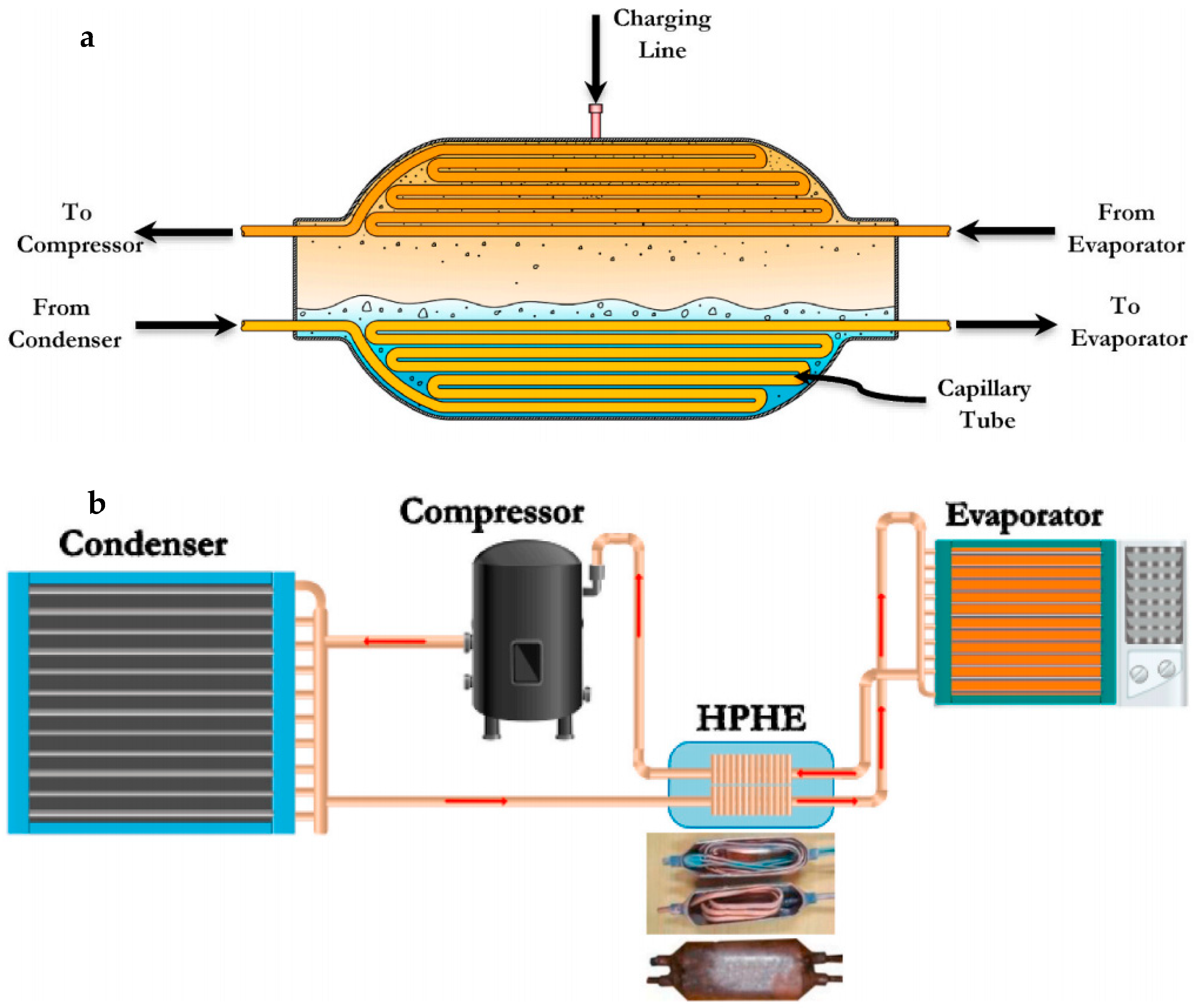
| Eidan et al. [56] | Experiment | Enhancing the performance of the SAC | GHP | Vertical | Distilled water, acetone and R134a | 50–100% | N | Y | The refrigeration effect was enhanced by 3.5, 6.03 and 3.97% for a 100% filling ratio of R134a, acetone, and water, compared to the window-type air conditioner without the HPHE. The consumed power saving of the window-type air conditioner with the HPHE were 2.01, 2.195 and 1.33% for water, acetone and R134a, respectively. |
| Xia et al. [98] | Experiment and simulation | Enhancing the performance of the SAC | - | Vertical | Water | - | Y | - | L-type HPHS was more advantageous in terms of thermal management and had average temperature reductions of 10.0 °C and 5.9 °C for small power chips and large power chips, respectively. |
| Nakkaew et al. [99] | Experiment | Enhancing the performance of the SAC | Wicked HP | Horizontal | Deionized water | 1.21–1.31 cc | Y | Y | The maximum heat transfer rate obtained from the HPHE was about 240 W. The EER of the proposed SAC increased by about 3% and was fractionally higher than that of the traditional SAC. |
| Wu et al. [100] | Experiment | Air supply dehumidification | GHP | Vertical | R22 | 60% | Y | - | The relative humidity of the air stream passing through the condenser of the HPHE could be reduced to 70–74% from 92–100%. The heat recovery of 1920–2504.5 kJ/h was obtained. A cooling capability improvement by 20–32.7% was also discovered for the CC. |
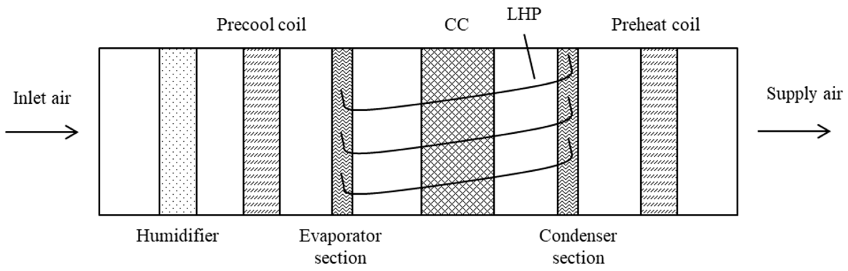
| Jouhara and Meskimmon [101,112] | Experiment | Air supply dehumidification | LHP | Horizontal | Water and R134a | - | Y | Y | The effectiveness of the HP decreased with the increase of the supply air velocity. The performance of the water HP was better than that of the R134a HP with an increase of about 18%. |
| Barrak et al. [102] | Experiment | Air supply dehumidification | PHP | Vertical | Distilled water, methanol and mixture fluid | 50% | Y | N | The total energy saving was increased with the increase in the air velocity. The maximum total energy saving reached 1645, 1849 and 1932 W for water, mixture fluid and methanol, respectively. The inlet relative humidity had a more significant effect on the sensible heat ratio |
| Firouzfar et al. [103] | Experiment | Air supply dehumidification | GHP | Vertical | Methanol, methanol-silver nanofluid | 50% | Y | N | HPHE using methanol-silver nanofluid had a better performance than that of using pure methanol. |
| Sarkar [114] | Simulation | Air supply dehumidification | - | Horizontal | - | - | - | - | Annual cooling energy savings of the proposed system were 1.5–19% for the six climate zones. The indoor temperature and relative humidity unmet hours were below 300. |
| Yau [104,105] | Experiment | Air supply dehumidification | GHP | Vertical | - | - | Y | N | The influence of the inlet dry bulb temperature on the sensible heat ratio was not so significant compared to the inlet relative humidity. |
| Ahmadzadehtalatapeh and Yau [24] | Experiment and simulation | Air supply dehumidification | - | Horizontal | - | - | Y | - | Performances of the ACS integrated with the HPHE were improved, and a considerable amount of energy and power was saved when the 8-row HPHE was used. |
| Yau and Ahmadzadehtalatapeh [107] | Experiment and simulation | Air supply dehumidification | Wicked HP | Horizontal | R134a | 110% | Y | Y | The dehumidification of the CC coupled with the HPHE was improved by 6%. The payback period for the proposed system was about 1.9 years. |
| Wan et al. [108] | Experiment | Air supply dehumidification | LHP | - | - | - | - | - | The cooling and total energy savings were 23.5–25.7% and 38.1–40.9%, respectively, in the room design temperature of 22–26.8 °C and relative humidity of 50% for the case office building. |
| Guo et al. [57] | Experiment | Air supply dehumidification | LHP | - | R134a | - | Y | - | The energy saving and the dehumidification capacity improvement were obvious for the ACS coupled with the PASHP. |
| Supirattanakul et al. [109] | Experiment | Air supply dehumidification | PHP | Vertical | R134a, R22 and R502 | - | N | N | The highest peak value of the COP and EER of the proposed ACS were increased by 14.9% and 17.6%, respectively. |
| Kusumah et al. [110] | Experiment | Air supply dehumidification | Wicked HP | Vertical | Water | - | N | Y | HPHE performed best when a maximum number of HPs was achieved. The energy saving and the maximum effectiveness of the HPHE were 608.45 W and 7.64%, respectively. |
| Hakim et al. [111] | Experiment | Air supply dehumidification | Wicked HP | Vertical | Water | 50% | Y | Y | The highest effectiveness of the two-row HPHE reached 12.4% under conditions of the inlet air speed of 1.5 m/s and inlet air temperature of 35 °C. |
| Li and Ju [113] | Experiment and simulation | Air supply dehumidification | LHP | Horizontal | R22 | 52–97% | Y | - | The sensible and total effectiveness increased with the increasing inlet air temperature and filling rate. However, these values would decrease when the inlet air temperature and filling rate exceeded 38 °C and 88%, respectively. |
| Noie-Baghban and Majideian [115] | Experiment and simulation | Waste heat recovery | Wicked HP | Vertical | Methanol, acetone and water | - | N | Y | Methanol had the larger merit compared to water and acetone. The maximum effectiveness of the HPHE was 0.16. |
| Jadhav and Lele [116] | Simulation | Waste heat recovery | - | - | - | - | - | - | The maximum energy saving potential was for hot and dry, warm and humid, and composite Indian climatic zones. |
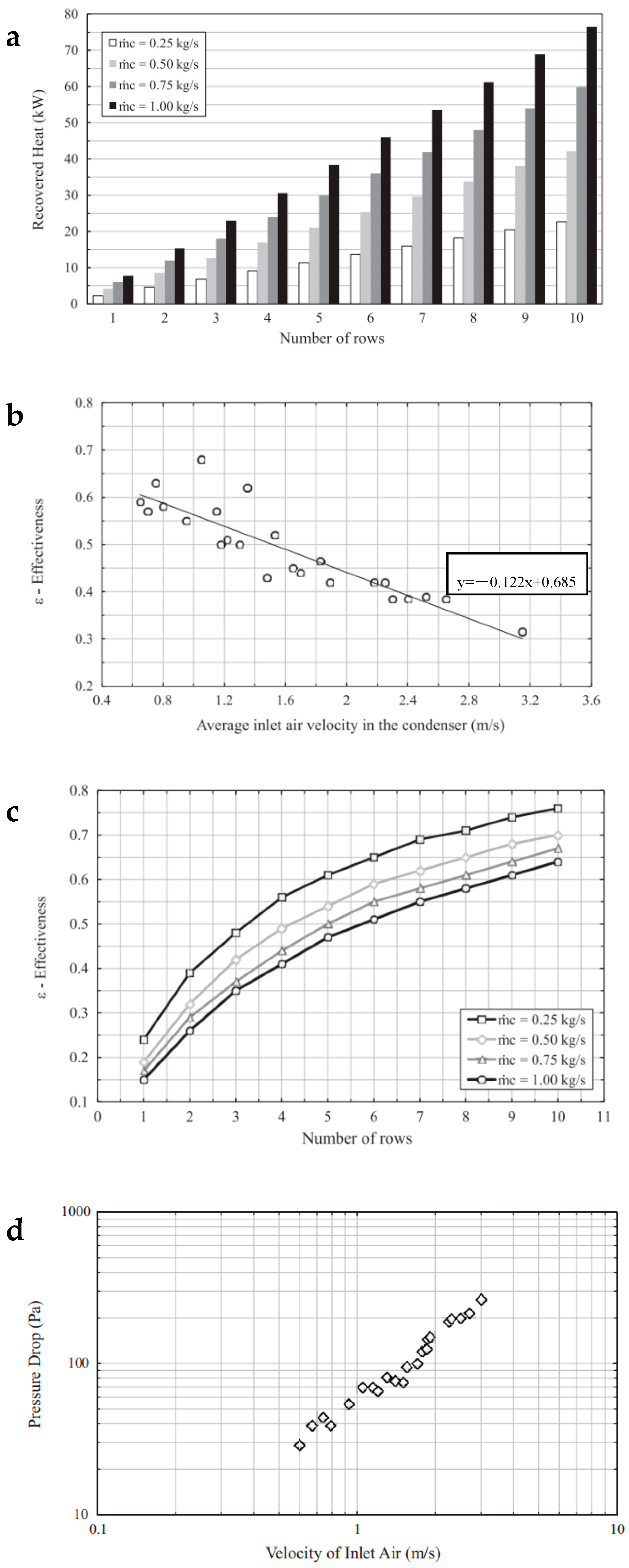
| Danielewicz et al. [117] | Experiment and simulation | Waste heat recovery | GHP | Vertical | Methanol | - | Y | N | The effectiveness and heat recovery of the HPHE increased with an increasing number of rows. The pressure loss of the HPHE increased with the increase in the inlet air speed. The effectiveness decreased with the increase in the inlet air speed. |
| Putra et al. [118] | Experiment | Waste heat recovery | THP | Vertical | Water | 50% | Y | - | When the inlet air temperature and velocity were 45 °C and 2 m/s, the maximum heat recovery capacity of HPHE was 1404.29 kJ/h. |
| Muhammaddiyah et al. [119] | Experiment | Waste heat recovery | Wicked HP | Vertical | Water | 50% | Y | Y | The maximum effectiveness was approximately 54% under the conditions of minimum air speed and maximum air temperature. |
| Sukarno et al. [120,121,122] | Experiment | Waste heat recovery | Wicked HP | Vertical | Water | 50% | Y | Y | The maximum effectiveness was over 60% under the conditions of air speed of 2 m/s and maximum air temperature. When the Reynold number increased, the Sp number increased. However, when the effectiveness increased, the Sp number had the opposite variation tendency. |
| Abd El-Baky and Mohamed [123] | Experiment | Waste heat recovery | Wicked HP | Horizontal | R134a | - | Y | Y | The effect of airflow rate on effectiveness had a little positive correlation for the evaporator section and a largely negative correlation for the condenser section. The maximum effectiveness and the enthalpy ratio were about 48 and 85%, respectively. |
| Abdelaziz et al. [124] | Experiment | Waste heat recovery | GHP | Horizontal | R123 | - | Y | N | The energy consumption reduced by approximately 30% for the ACS coupled with the HPHE. The payback period of the proposed system was approximately 3 years. |
| Mahajan et al. [125] | Experiment | Waste heat recovery | PHP | Vertical | n-pentane | 0–70% | N | N | The effectiveness of 0.05 and the effective thermal resistance of 0.11 °C/W were obtained at a filling ratio of 70%. |
| Mahajan et al. [126] | Simulation | Waste heat recovery | PHP | Vertical | Acetone | - | Y | N | The effectiveness of the PHPHE reached 0.48. The total average annual energy consumption and running cost could be reduced by 16% and USD 700 for the proposed system in the commercial building. |
| Yang et al. [127] | Experiment | Waste heat recovery | PHP | Vertical | R134a | 50% | N | N | An installation angle of 60 degree was a maximum value for the PHPHE. The recovery effectiveness of the PHPHE increased with the increasing inlet air temperature. However, it decreased with the increasing wind velocity. |
| Shen et al. [128] | Experiment | Waste heat recovery | FHP | Vertical | R600A | 26% | Y | N | The heat transfer efficiency of the parallel-flow HPHE increased with the increasing airflow rate, while the thermal resistance decreased. |
| Liu et al. [129] | Experiment and simulation | Waste heat recovery | LHP | Horizontal | Water and methanol | - | Y | N | The length of the evaporator had almost no impact on the upper boundary but had a significant effect on the lower boundary. The operation ranges of the LHP varied with the working fluids. |
| Xue et al. [130] | Experiment | Waste heat recovery | LHP | Horizontal | R32 and R134a | 40% | Y | N | The highest temperature effectiveness was 62 and 70% for winter and summer working conditions, respectively. |
| Zhou et al. [131,132] | Experiment | Waste heat recovery | LHP | Horizontal | R32, R22 and R152a | - | Y | N | The heat transfer capacity and COP of the PLHP heat recovery system increased with the indoor-outdoor temperature difference. However, the temperature effectiveness showed an opposite trend. PLHP performed better with R32 as the working fluid than with R22 and R152a. |
| Liu et al. [133,134] | Experiment | Waste heat recovery | LHP | Horizontal | R32 | - | Y | N | The CLHP heat recovery system performed better than that of PLHP and BLHP when the ambient temperature exceeded about 35 °C or was below 8 °C. |
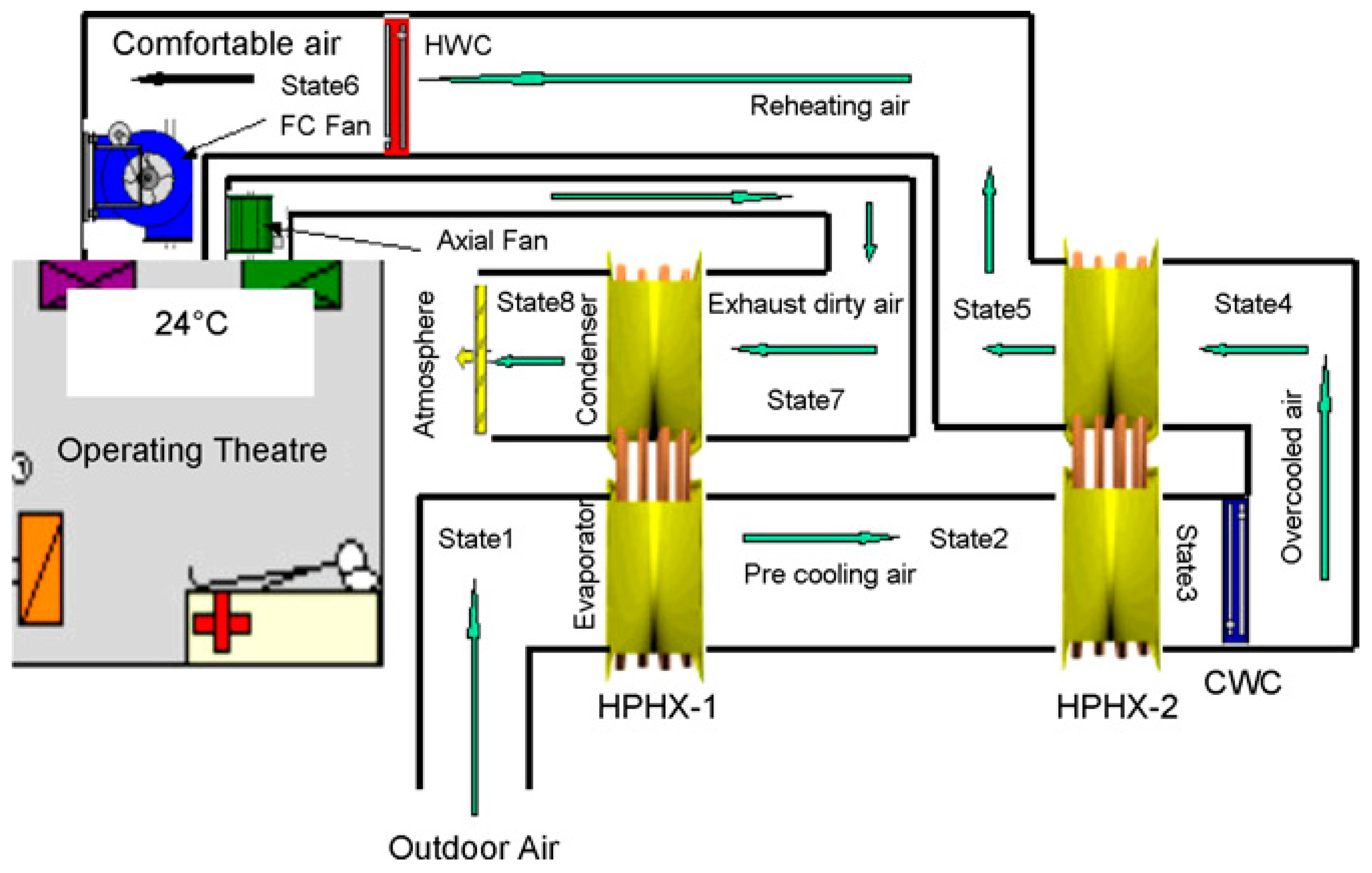
| Ahmadzadehtalatapeh and Yau [135], Yau [136] | Experiment and simulation | Air supply dehumidification and waste heat recovery | GHP | Vertical | - | - | Y | N | When the ACS was integrated with HPHE, the annual energy saving could reach to 27.48 MWh. The payback period of the ACS coupled with the HPHE was about 4 years. |
| Martínez et al. [137] | Experiment | Air supply dehumidification and waste heat recovery | Wicked HP | Horizontal | Ammonia | 3.04 g | Y | Y | The heat recovery efficiency had a linear relationship with the outdoor temperature and airflow factors, and an extreme COP value 9.83 of the study system was obtained. |
| Wang et al. [138] | Experiment and simulation | Air supply dehumidification and waste heat recovery | Wicked HP | Horizontal | Ammonia | - | Y | Y | The average heat recovery efficiency of the proposed system was 21.08% and 39.2% in winter and summer, respectively. The energy saving advantage of the novel system was outstanding compared to the common heat recovery system. |
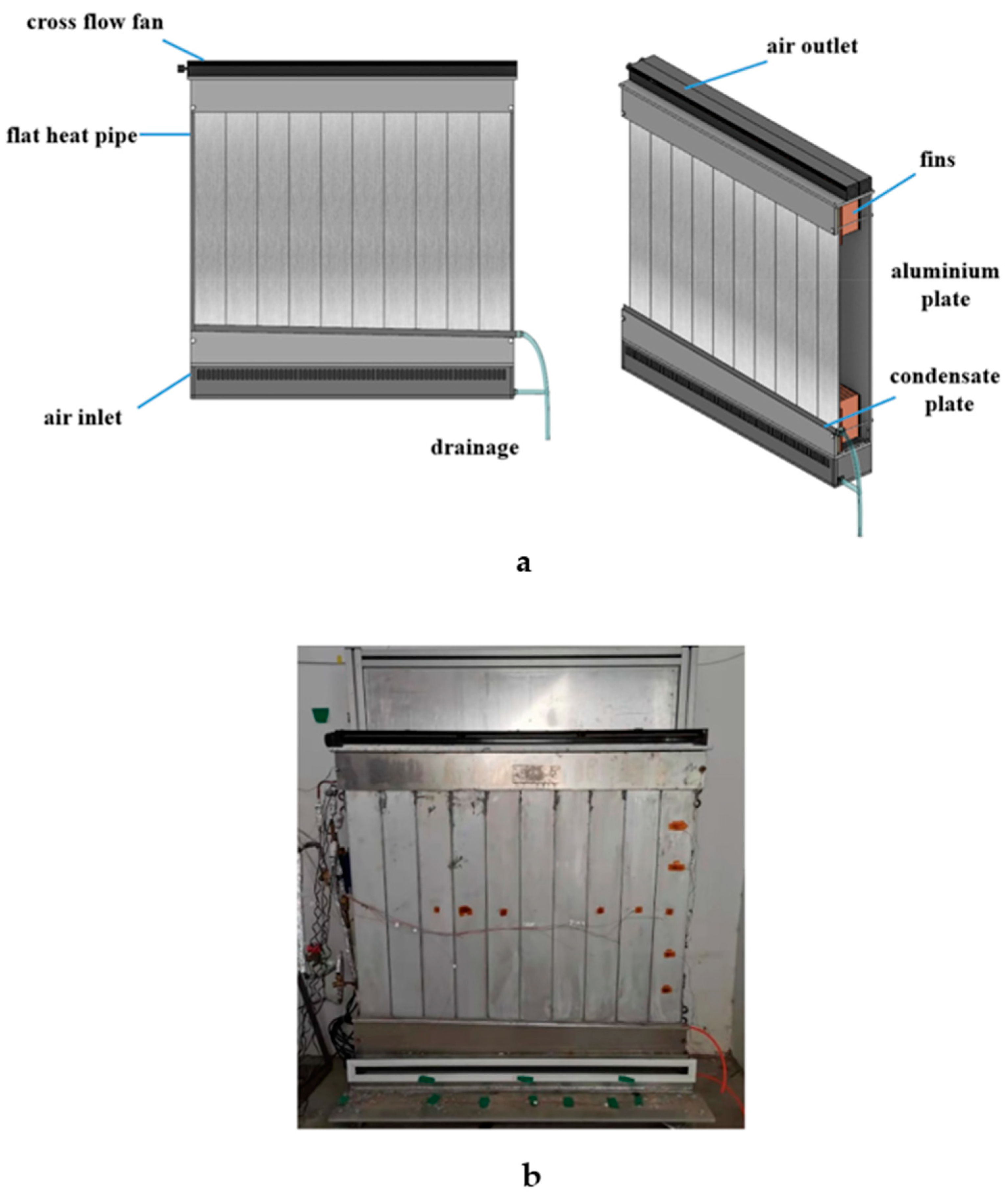
| Sun et al. [68] | Experiment | Design a cooling radiator | FHP | Vertical | Acetone | 15% | Y | N | The FHP radiator had a speed start-up time with a value of 245–385 s. The cooling capacity of the FHP radiator varied from 40.1 W/m2 to 75.8 W/m2. Cold source temperature had an important impact on the thermal performance of the FHP radiator. |
| Wu et al. [139] | Experiment | Design a cooling radiator | FHP | Vertical | Acetone | 20% | Y | N | The cooling radiator had a uniform surface temperature and a faster thermal response time with a value of about 360 s. The surface temperature and cooling capacity of the FHP simultaneously increased by 4–6 °C and 75.7%, respectively, under the force convection running strategy. |
| Zhao et al. [140] | Experiment | Design a cooling radiator | FHP | Vertical | Acetone | 20% | Y | N | When the cross flow fan was open and ran at the highest velocity, the cooling capacity was 2.24 times that of pure radiation mode. The indoor relative humidity could be controlled quickly. |
Disclaimer/Publisher’s Note: The statements, opinions and data contained in all publications are solely those of the individual author(s) and contributor(s) and not of MDPI and/or the editor(s). MDPI and/or the editor(s) disclaim responsibility for any injury to people or property resulting from any ideas, methods, instructions or products referred to in the content. |
© 2023 by the authors. Licensee MDPI, Basel, Switzerland. This article is an open access article distributed under the terms and conditions of the Creative Commons Attribution (CC BY) license (https://creativecommons.org/licenses/by/4.0/).
Share and Cite
Yuan, T.; Liu, Z.; Zhang, L.; Dong, S.; Zhang, J. The Review of the Application of the Heat Pipe on Enhancing Performance of the Air-Conditioning System in Buildings. Processes 2023, 11, 3081. https://doi.org/10.3390/pr11113081
Yuan T, Liu Z, Zhang L, Dong S, Zhang J. The Review of the Application of the Heat Pipe on Enhancing Performance of the Air-Conditioning System in Buildings. Processes. 2023; 11(11):3081. https://doi.org/10.3390/pr11113081
Chicago/Turabian StyleYuan, Tianhao, Zeyu Liu, Linlin Zhang, Suiju Dong, and Jilong Zhang. 2023. "The Review of the Application of the Heat Pipe on Enhancing Performance of the Air-Conditioning System in Buildings" Processes 11, no. 11: 3081. https://doi.org/10.3390/pr11113081
APA StyleYuan, T., Liu, Z., Zhang, L., Dong, S., & Zhang, J. (2023). The Review of the Application of the Heat Pipe on Enhancing Performance of the Air-Conditioning System in Buildings. Processes, 11(11), 3081. https://doi.org/10.3390/pr11113081