Article

Optimization of Hydraulic Fine Blanking Press Control System Based on System Identification

1
Hubei Key Laboratory of Advanced Technology for Automotive Components, Wuhan University of Technology, Wuhan 430070, China
2
Hubei Collaborative Innovation Center for Automotive Components Technology, Wuhan University of Technology, Wuhan 430070, China
*
Authors to whom correspondence should be addressed.
Processes 2023, 11(1), 59; https://doi.org/10.3390/pr11010059
Submission received: 17 October 2022 / Revised: 12 November 2022 / Accepted: 21 November 2022 / Published: 27 December 2022
(This article belongs to the Special Issue Modeling, Simulation and Control of Flexible Manufacturing Systems)

Abstract

:
Fine-blanking is a molding process based on the common blanking process, which obtains hydrostatic stress through blank holder reverse jacking, in order to increase material plasticity. It requires special equipment, namely a fine-blanking press, to complete the fine-blanking process. In this paper, the problem of the speed of the slide block fluctuation found in the actual use of a 12,000 kN hydraulic fine-blanking press after multi-stage pressure source optimization is studied. Firstly, the mathematical model of the motion of the slide block in the blanking stage of the hydraulic fine blanking press is established, and the accurate mathematical model in the blanking stage of the hydraulic fine-blanking press is obtained through the least square method system identification experiment. Aiming at the complex working situation of the fine-blanking press, a phased PID control strategy is creatively proposed. The optimal PID control parameters are obtained by a genetic algorithm, and established a fuzzy PID controller for the blanking stage to accurately control the movement speed of the slide block. The results show that the new control strategy is very effective in improving the movement accuracy of the slide block, effectively improving the machining accuracy and reducing the impact vibration of the hydraulic system.

Graphical Abstract

1. Introduction

As an advanced plastic forming process, the fine-blanking (FB) process has been widely used in industry because of its high efficiency and high part quality [1,2]. Many sheet metal components (thickness from 2 mm to 20 mm) with a complex shape and high dimensional accuracy can be processed at one time through the FB process. The fine-blanking press (FBP) is a special press machine designed and manufactured to complete the FB process. It is a kind of high-end manufacturing equipment. In contrast to ordinary presses, the FBP needs to be able to provide blanking force, blank holder force and counter punch force at the same time [3], and requires high stiffness and machining accuracy to meet the process requirements of FB [4].
In the process of FB, the press needs to provide three main movements: the movement of the slide block, counter punch movement and blank holder movement. Among them, the main movement includes the following stages: the first is the fast approaching (FA) stage. Under the action of the oil cylinder, the slide block begins to move rapidly upward from the bottom dead center and quickly approaches the sheet metal. When the slide block moves close to the sheet metal, it enters the detection (DT) stage. The movement speed of the slide block slows down to detect whether there is waste residue on the die surface. If waste residue is present, the slide block returns to the bottom dead center and stops the machine; if not, the slide block continues to rise to enter the next stage. When the slide block moves to the blanking point, it enters the blanking (BL) stage. The slide block is driven by the fast subsystem oil cylinder, and is altered to be driven by the main blanking subsystem oil cylinder with high pressure and large flow rate in order to complete the blanking and forming process of parts at a low speed. After the BL stage, it enters the fast returning (FR) stage, and the fast subsystem cylinder drives the slider to return to the bottom dead center, quickly, from the upper dead center.
The hydraulic valve control system is widely used in traditional hydraulic FBPs due to its good control performance, fast response and simple operation [5]. However, the large tonnage hydraulic FBP uses a fixed value high-pressure source to drive the load, resulting in a serious mismatch between the system output power and multiple load requirements, which cause the energy efficiency of the system to be very low. In order to solve the problem of the mismatch between the system output power and load power, our research group proposed a novel multi-stage pressure source drive system. For the 12,000 kN hydraulic FBP, a five-stage pressure source was used to replace the high-pressure source of the original equipment [6]. By using the multi-stage pressure source system, the energy loss of the high-pressure circuit of the equipment in one cycle was reduced by 34.86%. For the fast circuit, the servo motor is used to drive the quantitative pump to realize the supply-demand matching of fast circuit pressure and flow, and the energy loss of the medium press circuit can be reduced by 50.32%.
Although the multi-stage pressure source system has a remarkable energy-saving effect, the resistance of the system is greatly reduced. During the actual using process, the motion speed fluctuation of the slide block became larger, and the motion accuracy decreased, which cannot meet the precision requirements of the FB process. Therefore, how to improve the motion accuracy of the slide block and reduce the speed fluctuation of slide block have become new problems.
Scholars have conducted extensive research on the speed control and motion accuracy of the hydraulic system. Hua et al. studied and analyzed the speed fluctuation and vibration of forging machine tools [7]. Yang et al. designed a hydraulic speed control system of the crane anti-rolling device and studied the parameter matching of the main components, such as the hydraulic motor and hydraulic pump in the speed control system [8]. Fang et al. analyzed the fluid transmission features of the hydraulic control system for the press machine and designed the hydraulic control system [9]. The results show that the control system can effectively control the movement of the press. Wei et al. proposed an adaptive fuzzy sliding mode controller based on the Pi-sigma fuzzy neural network in combination with the Pade approximation, which is itself based on the common pressure rail system for hydraulic transformers [10]; the result shows that it has strong robustness. Neha et al. presents an optimization technique method for the particle swarm optimization (PSO) algorithm for tuning the proportional-integral-derivative (PID) controller parameters for the electro-hydraulic servo system [11]. Tanasak Samakwong et al. considered the optimization technique of Genetic Algorithm (GA) for tuning the PID controller parameter for the electro-hydraulic servo system [12]; the results show that it has a good closed-loop performance. Liu et al. put forward a compound algorithm of proportional integral and speed feed forward displacement feedback [13], the research finds that the proposed position scheme is effective in increasing the position precision. Bing et al. designed and analyzed the speed control system of the variable voltage variable frequency (VVVF) hydraulic elevator with the pressure accumulator [14]. They carried out a comparison of the experimental research of energy-saving for the speed control of the VVVF hydraulic elevator, with and without the pressure accumulator. The experimental results show that the VVVF hydraulic elevator with the pressure accumulator has higher efficiency compared with the VVVF hydraulic elevator without the pressure accumulator. Jiang et al. took a servo motor quantitative pump hydraulic cylinder load as the main dynamic line [15]. They studied the multiparameter characteristics of the system under the electromechanical-hydraulic coupling conditions and provided a theoretical basis and guidance for the high-performance control of the system. Zhang et al. proposed a flow-limited rate control scheme for the master-slave hydraulic manipulators [16]. They developed the variable velocity mapping by adjusting the velocities to meet the pump and valves’ flow limits and designed an adaptive robust rate controller of hydraulic manipulators. In addition, they introduced an adaptive boundary estimator to estimate the hydraulic manipulator acceleration boundaries, and a variable structure controller is used to plan the velocities to meet the dynamic limits. The results showed that the control scheme reduced the velocity error and avoided the manipulator vibration; thus, the performance of the hydraulic manipulator was improved. In order to solve the problems of slow response, poor precision, and the weak anti-interference ability in the hydraulic servo position controls, Guo et al. designed a Kalman genetic optimization PID controller [17]. The designed Kalman genetic optimization PID controller can be better applied to the position control of the hydraulic servo system. The Kalman filter is a good solution for the amplitude fluctuations caused by GA-optimized PID that reduces the influence of external disturbances on the hydraulic servo system. Although there has been a lot of research on the speed control of the hydraulic system, no research has been conducted on the combined control of the hydraulic valve and pump. Most of the existing research on speed control and speed fluctuation suppression of the hydraulic system focus on algorithms, and the applications are simple systems. However, for complex systems, such as complex the hydraulic system of FBP, due to the dynamic system being difficult to analyze, it has proven challenging to design effective controllers; therefore, there has been very little research on this topic. For complex systems, the system identification method is generally used to obtain their transfer functions. Researchers have conducted extensive research on the system identification of the hydraulic system. Maier et al. put forward nonlinear parameter identification for hydraulic servo-systems with switching properties [18], which provided an optional idea for the system identification of the hydraulic system. Aiming at the modeling and control problems of the hydraulic turbine system, Jiang et al. proposed a hydraulic turbine system identification and predictive control based on the genetic algorithm-simulate anneal and back propagation neural network (GASA-BPNN) [19]. Compared with the output response of the traditional control of the hydraulic turbine governing system, the neural network predictive controller used by Jiang has better effect and stronger robustness, solves the problem of poor generalization ability and identification accuracy of the turbine system under variable conditions, and achieves a better control effect. This method provides a good guiding effect for hydraulic system identification. Tian et al. presented an improved whale optimization algorithm (IWOA) and its application in the parameter identification of hydraulic turbine at no-load [20]. Furthermore, in the identification process, the adaptive modification method is developed to solve the estimated parameter range uncertainty problem. The results show that IWOA has fast convergence and high precision. In order to improve the tracking accuracy of a hydraulic system, Feng et al. proposed an improved ant colony optimization algorithm (IACO) to optimize the values of the proportional-integral-derivative (PID) controller [21]. In addition, Feng presents an experimental study on the parameters identification to deduce accurate numerical values of the hydraulic system, which also determines the relationship between the control signal and output displacement. All the above research provides a good solution for hydraulic system identification. At the same time, they provide a theoretical basis for the establishment of the hydraulic control system.
In this paper, our group studied the problems of large velocity fluctuation and low motion accuracy of the slide block of the multi-stage pressure source FBP. In Section 2, the hydraulic system of FBP is introduced, and the mathematical model of the valve-controlled hydraulic cylinder is established. In Section 3, through the method of system identification, the transfer function of the key stage is obtained; that is, the BL stage. In Section 4, we proposed a multi-stage closed-loop control for the complex working process of the FBP using a genetic algorithm to find the best control parameters. For the BL stage with changing load, we established a fuzzy PID controller, so that it can meet various complex working requirements. The results show that the mathematical model obtained by this method has high accuracy, and the designed controller can effectively improve the motion accuracy of the slide block and reduce the speed fluctuation.

2. Materials and Methods

2.1. Hydraulic System of FBP and Its Modeling

2.1.1. Hydraulic System of Multi-Stage Pressure Source FBP

The hydraulic multi-stage pressure source FBP researched in this paper, with the capacity of 12,000 kN, was jointly designed and manufactured by our research group and company Wuhan Huaxia Fine-blanking Co., Ltd from Wuhan, China. Its hydraulic system includes the following subsystems: pressure source subsystem, fast subsystem, main blanking subsystem, counter punch subsystem, blank holder subsystem, die locking subsystem, upper die raceway subsystem, standby pressure subsystem front and rear clamping subsystem, waste scissors subsystem, etc. [22]. The material (metal plate) is transported to the hydraulic press through the upper die raceway subsystem, and the material is initially fixed through the die locking system. The FB processing process is completed in the FBP, and then the die locking system is opened, the processed parts and waste materials are collected, and the surplus materials are cut by the rear clamping subsystem. This paper will focus on the pressure source subsystem, fast subsystem and main blanking subsystem, as shown in Figure 1, which have a great impact on the machining accuracy, speed of slide block and machine performance. Before the FB process, the pressure source subsystem starts to work, and a pressure building process is carried out. The pressure source subsystem is mainly composed of motor, pump (P3, P4), switch cartridge valve and its cover plate (YV6–YV10), accumulator, pressure building cartridge valve and its cover plate (YV1–YV5). This subsystem is used to provide the required energy and pressure to the main blanking subsystem. During the working process, the motor pump continuously fills the accumulator with liquid to build pressure and store energy and pressure. When the accumulator reaches the set pressure, the proportional valve (YV1–YV5) in the cartridge valve cover plate controls the opening of the pressure building cartridge valve and the oil flows back to the oil tank through the pressure building cartridge valve. When the pressure source needs to supply flow to the outside, the pressure building cartridge valve is closed, the proportional valve (YV6–YV10) in the cartridge valve cover plate controls the opening of the switch cartridge valve, and the motor pump and accumulator jointly supply high-pressure oil to the corresponding external subsystems. The fast subsystem is composed of motor, pump (P1), switch cartridge valve and its cover plate (YV11), one-way valve, electromagnetic reversing valve (YV12), fast oil cylinder, etc. When the switch cartridge valve is opened, the oil flows into the lower or upper chamber of the oil cylinder through the servo valve and an electromagnetic reversing valve. The direction and speed of the piston rod movement are determined by the input signals of the electromagnetic reversing valve and the servo valve. The main blanking subsystem is composed of the switch cartridge valve and its cover plate (YV13), the speed regulation module, the charging valve and its control valve (YV15), the main oil cylinder, etc. Among them, the speed control module is composed of a pressure compensation valve and a servo valve (YB1) in series, which can ensure that the oil flow through is not affected by the pressure difference between the two sides and remains constant. The charging valve and its control valve mainly play the role of oil suction and drainage when the slide block quickly approaches and moves away from the workpiece. When the slide block quickly approaches the workpiece, the slide block drives the main piston to rise rapidly under the push of the fast piston rod, and the main oil cylinder automatically absorbs oil from the oil tank through the charging valve. In the blanking processing, the charging valve is closed to prevent the high-pressure oil from flowing back to the oil tank. When the slide block quickly moves away from the workpiece, the charging valve controls the pressurization of the oil port to open the valve, and a large amount of oil in the main cylinder flows back to the oil tank. The unloading cartridge valve is used for the quick unloading of the main cylinder at the end of blanking. When the blanking process is in progress, the fast subsystem works first, and the slide block is driven by the cylinder piston of the fast subsystem to quickly approach the materials to be processed. When it is close to the materials to be processed, the fast subsystem stops working. At this time, the main blanking subsystem works. The pressure source subsystem transfers the high-pressure oil to the oil cylinder of the main blanking subsystem, so that the slide block can process the necessary materials under the condition of high pressure and low speed. At the same time, the blank holder subsystem works to clamp the materials. After finishing the processing, the fast subsystem works to move the slide block away from the material by the oil cylinder of the fast subsystem. The counter punch subsystem works to completely separate the parts from the processing materials. For this system, the manipulated variables are the input electrical signals of each proportional servo valve and the motor of the fast subsystem. The controlled variables are the displacement and velocity of the slider. The disturbance variables are the resistance of the servo valve, the resistance of the system components, such as pipes, and the viscosity of the oil. The measurement process variable is the movement of the slider (displacement, velocity, acceleration, etc.). There are some improvements and optimizations between the FBP hydraulic system we use and the traditional FBP hydraulic system. For the fast subsystem, the servo motor is used to drive the quantitative pump to realize the supply-demand matching of the fast circuit pressure and flow. It is necessary to remove the accumulator and pressure building valve to allow the system can provide the required flow according to the slide block speed. The two position four-way reversing cartridge valve with smaller hydraulic resistance is used to replace the servo reversing valve with larger hydraulic resistance in the traditional system. For the pressure source subsystem, a five-stage pressure source is adopted, which is composed of five pressure units with different pressure levels in series. The motor pump fills the pressure units at all levels, from high pressure to low pressure, to form the corresponding pressure. The pre-charge pressure of the five accumulators is 35 bar, 65 bar, 95 bar, 125 bar and 155 bar, respectively. The supply pressure of the system can be automatically switched, according to the load pressure, to achieve the purpose of pressure and power supply on demand, in order to save energy. Due to the system resistance of this system being greatly reduced, the traditional open-loop control makes the rigidity of the servo motor and servo valve too high when switching working conditions of multi-stage pressure source FBP, and it cannot match the changing load. As a result, the motion accuracy of the slide block decreases, the speed fluctuation becomes larger, and the system vibration is serious.

2.1.2. Modeling of Valve Controlled Cylinder Electro-Hydraulic Position Servo System

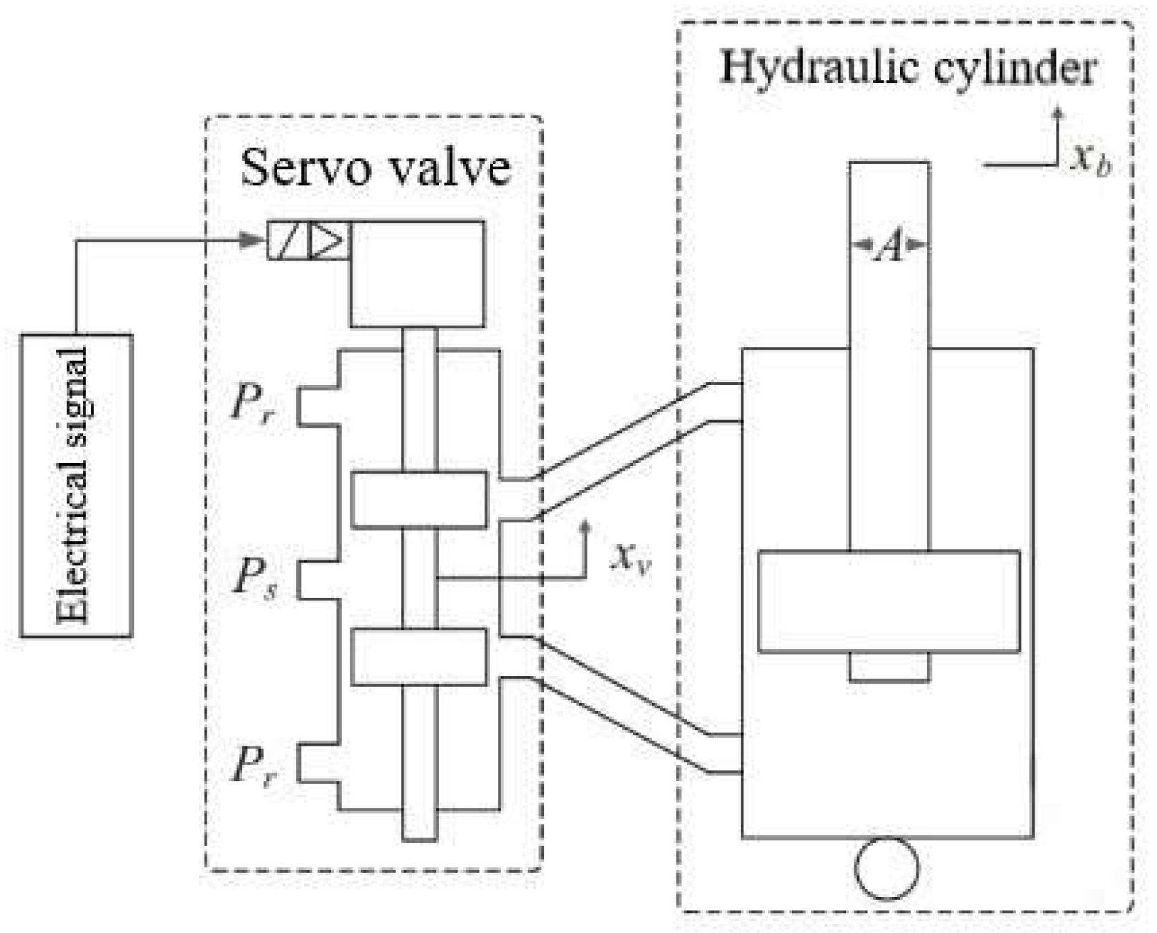
In this paper, the system mathematical model of the blanking stage of the FB press is obtained by means of system identification. Therefore, firstly, the valve-controlled cylinder system in the BL stage is theoretically modeled to roughly determine its model class, in order to lay a good foundation for the next system identification. The dynamic characteristics of the valve-controlled hydraulic cylinder depend on the characteristics of the valve and hydraulic cylinder and are related to the load. The differential equation describing the power components is nonlinear. The physical model of the valve-controlled cylinder system model used in this experiment is shown in Figure 2 [23]. In this figure, x v stands for the servo valve spool displacement; P r is the oil pressure returning to the system; P s is the system working pressure; A is the rod diameter of the hydraulic cylinder; x b stands for the hydraulic cylinder piston displacement.

2.1.3. Characteristic Analysis of Electro-Hydraulic Servo Valve

The electro-hydraulic servo valve is the core component of the hydraulic control system due to the pressure flow characteristic of the valve, the dead zone characteristic caused by Coulomb friction and the positive overlap of the valve, the nonlinear gain caused by the shape of the control window of the servo valve, the wind resistance nonlinearity and saturation nonlinearity caused by many factors such as transmission clearance, etc. Therefore, the hydraulic servo system is essentially a nonlinear control system. The servo valve usually takes current Δ i (mA) as the input parameter and no-load flow Q 0 = K Q x v (m3/s) as the output flow, where K Q is the flow gain of the servo valve. In most electro-hydraulic servo systems, the dynamic response of the servo valve is often higher than that of the power components. In order to simplify the system’s transfer function, it is generally expressed by the second-order oscillation link. At this time, the transfer function of the servo valve can be expressed as [24]:
Q 0 Δ I = K s v s 2 ω s v 2 + 2 ζ s v ω s v s + 1
where ω s v (Hz) is the natural frequency of the servo valve. The bandwidth of the servo valve usually takes the frequency corresponding to the amplitude ratio of—3 dB as the amplitude bandwidth and the frequency corresponding to the phase lag of 90° as the phase bandwidth, which can be selected according to the needs of control. ζ s v is the damping ratio of the servo valve; K s v is the flow gain of the servo valve; s is a complex parameter in the Laplace transform.
According to the phase frequency characteristic equation of the second-order link:
φ ( ω ) = arctg 2 ζ s v ω ω s v 1 ω ω s v 2
The value of ζ s v corresponding to each phase angle φ (rad) is calculated from the frequency characteristic curve, and then the average value is taken.
In most electro-hydraulic servo systems, the dynamic response of the servo valve is usually higher than that of the power components. Therefore, the transfer function of the servo valve can be further simplified and can generally be represented by a second-order oscillating link. If the natural frequency of the second order link of the servo valve is higher than the natural frequency of the power element, the transfer function of the servo valve can also be represented by the first-order inertial link. When the natural frequency of the servo valve is far greater than the natural frequency of the power element, the servo valve can be regarded as a proportional link. The first-order inertia link can be estimated by the following equation:
Q 0 Δ I = K s v s ω s v + 1
where ω s v (Hz) is the turning frequency of the servo valve, which is generally the frequency corresponding to the 45° phase lag on the frequency characteristic curve.

2.1.4. Dynamic Characteristic Equation of Valve Controlled Cylinder Electro-Hydraulic Position Servo System

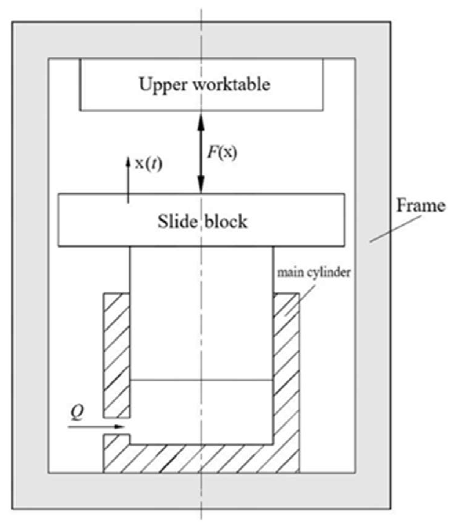
The hydraulic cylinder that controls the slide block movement in the BL stage in this paper is shown in Figure 3. After the oil, with p h (MPa) output pressure from the high-pressure source passing through the speed regulation module, the output flow Q (m3/s) is sent to the main blanking subsystem oil cylinder to drive the main piston to complete the corresponding FB process. With the increase in the slide block stroke, the total FB force increases. In addition to driving the piston movement, a part of the oil input to the main blanking subsystem cylinder needs to be used to compensate for the oil compression and elastic deformation of the frame, oil cylinder and pipeline [25]. Due to the large blanking tonnage and wide variation range of the blanking force, the above factors cannot be ignored for the kinematic analysis of the slide block.
Suppose that the starting point of the slide block stroke at the beginning of blanking is x = 0 , and after time t (s), the rising stroke of the slide block is x ( t ) (m). When the time increment is d t , the oil volume increment of the cylinder is:
d V = q d t
This oil volume is mainly used in the following four aspects:
  • First item, the volume of oil used to drive the main piston is:
    d V 1 = A d x
    where A (m2) is the effective working area of cylinder and d s (m) is the stroke increment of the movement of slide block.
  • Second item, the oil volume used to compensate for the elastic compression of the oil is:
    d V 2 = V 0 + A x F x d x E y
    where V 0 (m3) represents the initial volume of the cylinder when the slide block is at the starting point of the blanking stroke, and E y (Pa) represents the elastic modulus of the oil.
  • Third item, when the oil volume used to compensate the elastic deformation of the frame is F ( x ) , the frame will be elastically deformed and further elongated, increasing the volume of the upper chamber of the working cylinder by d V 3 , which must be supplemented by additional oil.
    d V 3 = d F ( x ) K j A
    where d F ( x ) is the increment of the total FB force with the stroke, and K j (N/m) represents the longitudinal stiffness of the frame.
  • Fourth item, used to compensate the elastic expansion deformation of the main blanking subsystem oil cylinder:
d V 4 = 2 π r 0 F ( x ) x K g d x
where r 0 (m) represents the initial radius of the cylinder and K g (N/m) represents the radial stiffness of the cylinder.
According to simultaneous Equations (4)–(8) and d v = d v 1 + d v 2 + d v 3 + d v 4 , the running speed of the slide block is:
v = d x d t = q A + ( V 0 + A x E y A + A K j + 2 π r 0 x K g ) F ( x )
It can be seen from Equation (9) that in the blanking stage, the movement speed of the slide block mainly depends on the oil supply q of the speed regulation module, and q is determined by the input electrical signal of the servo valve Δ i .

2.2. System Identification in BL Stage of FBP

For the complex hydraulic system, the accurate mathematical model of the object can be obtained more accurately by using the method of system identification [26,27]. In this paper, the system identification experiment is used to obtain the accurate system transfer function in the BL stage, which lays a good foundation for the subsequent controller design.
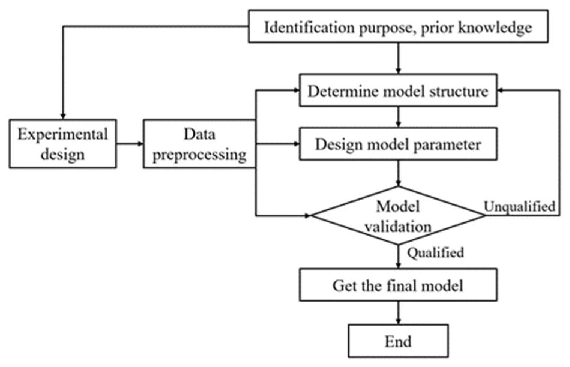
The theory and method of establishing the mathematical model of the system according to the input and output data of the system is called system identification. The basic steps are shown in Figure 4.
System identification is based on the acquisition of the output response of the research object under the action of human made input. The acquired data need to be processed. Finally, the estimation of the object mathematical model must be realize. There are three elements of system identification:
  • Input and output data: Data is the basis of system identification
  • Model class: Find the scope of the model and determine the structure of the model
  • Equivalence criterion: It is the optimization objective of identification and is used to measure the proximity between the model and the actual system.

2.2.1. Design of Identification Experiment

The design of the identification experiment includes the selection of the input signal and the determination of the sampling time and experimental time. Through the experimental design, the internal characteristic information of the system should be included in the collected input and output data, as much as possible, in order to carry out accurate system model identification.
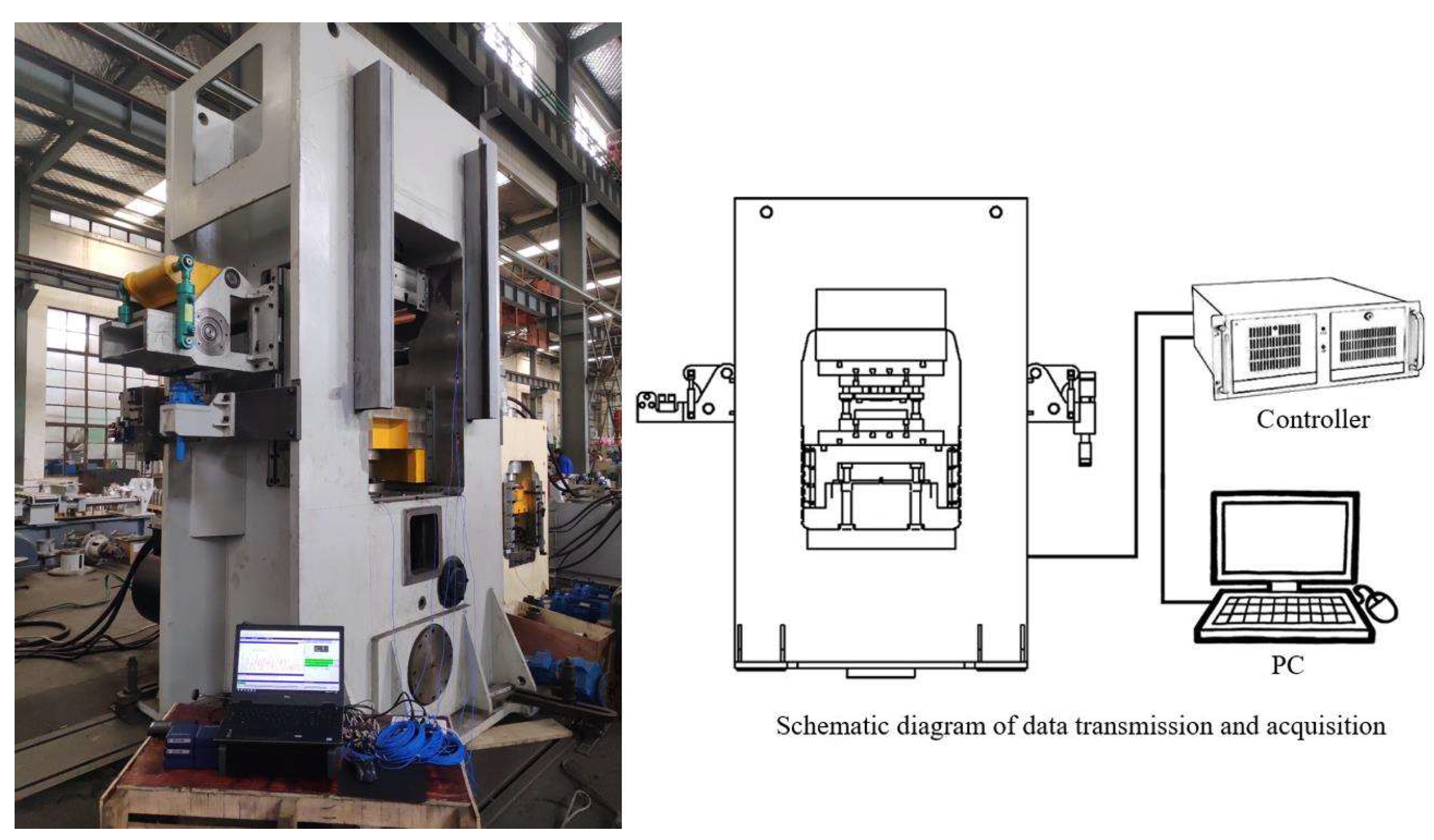
The multi-stage pressure source FBP is equipped with a Balluff displacement sensor, IFM pressure sensor and Advantech industrial computer. The displacement sensor collects the displacement of the slide block, and the pressure sensor collects the pressure of the fast subsystem oil cylinder, main oil cylinder, counter punch oil cylinder and blank holder oil cylinder. The collected data transmit to the industrial control computer in real time. The industrial control computer is equipped with the Siemens PLC program control system, which can store the data of one operation cycle of the system. The stored data can be downloaded through the PLC programming software Siemens step 7. The main hardware models are shown in Table 1. The system uses Siemens touch screen KTP1200 based on Windows CE to design the operation interface. The FB production line and data acquisition site are shown in Figure 5.
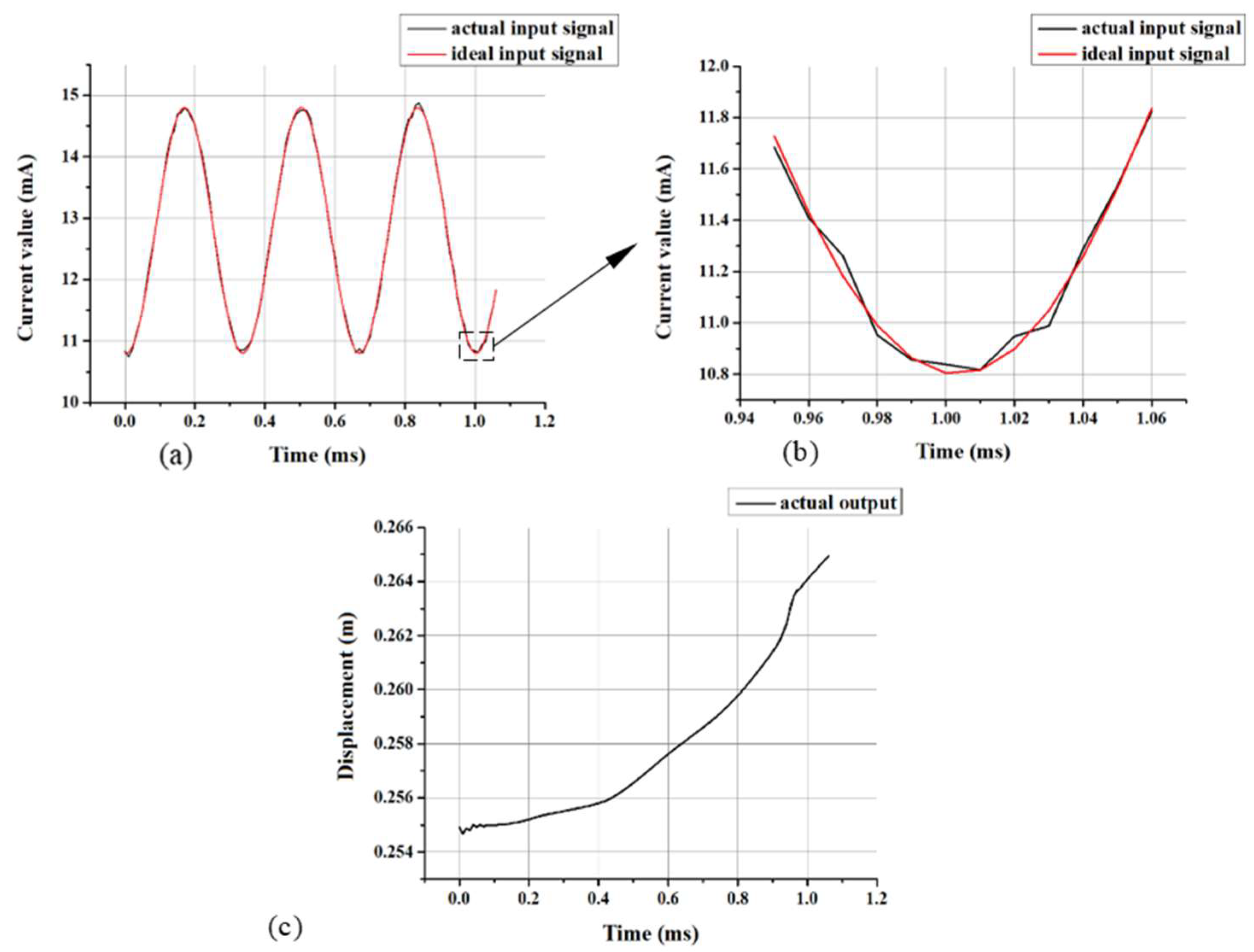
In this experiment, the signal generator is used to apply the input signal to the system, change the input current signal of valve YB1, and adjust the spool opening by changing the input current signal of the valve. Further, the signal generator is also used to change the flow characteristics of the main oil circuit in the blanking stage, then change the speed of slide block, and measure the displacement of slide block as the output signal. The servo valve used in this experimental equipment can accept an input electrical signal of 0–40 mA. When the input electrical signal is 40 mA, the valve port is opened to the maximum, and when the input electrical signal is 0 mA, the valve port is closed. In actual use, when the valve opening reaches 1/4 of the maximum value, the hydraulic oil flow rate will not be too high due to the small valve opening, which will not lead to abnormal operation of the equipment. Generally, when the FBP works normally, the electrical signal of the servo valve port is generally 10–15 mA. As system identification requires an input signal to fully stimulate all working states of the experimental object within a certain range, sinusoidal signal sweep input is often used. Moreover, as the response time of the servo valve is generally 0.1 s, it is most reasonable to select a sinusoidal signal with a frequency smaller than 10 Hz as the input signal. A sine input signal with an average input of 12.8 mA, positive and negative 2 mA, and a frequency of 3 Hz is designed. As the hydraulic multi-stage pressure source FBP is a typical perturbation system, in the experiment, the equipment is operated, without load, one minute before, and the input electrical signal of hydraulic valve YB1 and the displacement of the slide block output signal in the BL stage are collected one minute later. Measuring multiple groups of valid data after the system runs stably, two groups of data are extracted as identification data. One group is used as the identification data set, and the other group is used as the verification data set. The experimental ideal input signal (designed sine input signal) and the actual input signal are shown in Figure 6a,b. The actual input signal fluctuates sharply, which is caused by the unavoidable error caused by the surrounding environment during use. The measured actual output is shown in Figure 6c.

2.2.2. Selection of System Model

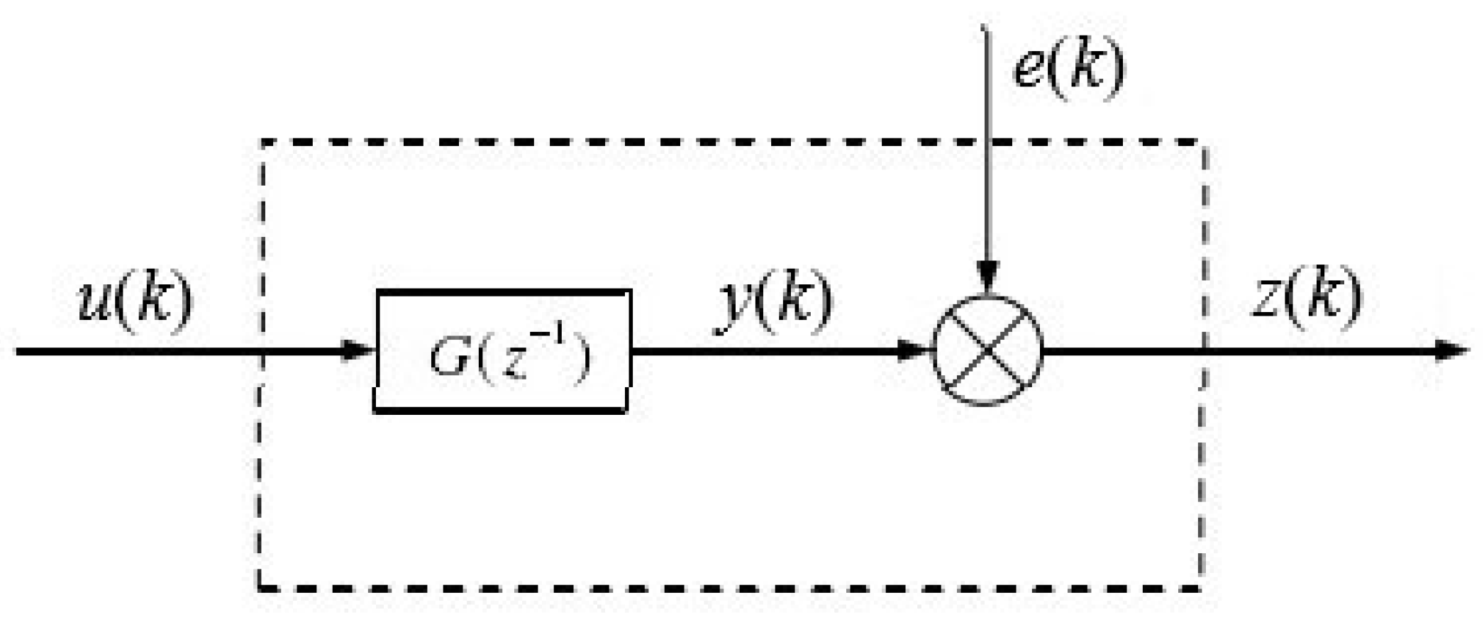
In this experiment, the output data is generated by applying the input signal to the system, so the system model contains the control quantity; therefore, the autoregressive exogenous (ARX) model with the control quantity is selected [28]. The ARX model considers all inputs before a specific time and the current white noise. This model has a simple algorithm and strong robustness. If the noise in the system is large, the model order can be appropriately improved to obtain higher identification accuracy. The hydraulic system used in this experiment is often accompanied by substantial noise interference due to the working environment of FBP equipment, so it is more suitable to use the ARX model. As shown in Figure 7, this model is excited by the input signal u ( k ) and superimposed with the noise signal e ( k ) . It can be expressed by the following equation:
A z 1 z k = z d B z 1 u k + e k

2.2.3. Determination of Model Order of System Parameters

If the order of the system model is not appropriate, it may cause serious problems in the design of the control system. There are many methods to determine the order of the model, such as the F-test, Akaike information criterion (AIC) [29], final prediction error (FPE), Hankel matrix order determination, etc. AIC encourages the goodness of data fitting but tries to avoid overfitting. Therefore, the priority model should be the one with the lowest AIC value. The method of AIC is to find the model that can best explain the data but contains the least free parameters. FPE is the final prediction error, the parameter n that minimizes FPE (n) is called the estimation of the order p of AR (p) model. This method is the so-called improved residual variance graph method, proposed by Akaike in 1969. Therefore, order determination based on this criterion is in line with the practical purpose. It has the advantage of high calculation efficiency and is very suitable for the error calculation of hydraulic system identification. Therefore, in this paper, the AIC method and the FPE method are used:
E σ ^ z 2 = L + n a + n b L n a + n b E σ ^ ε 2
The above equation is the expression of the final prediction error criterion, which is recorded as F P E n a , n b :
F P E n a , n b = E σ ^ z ˜ 2 = L + n a + n b L n a + n b E σ ^ ε 2 = L + n a + n b L n a + n b × 1 L ε T ε = L + n a + n b L n a + n b × J n a + n b L
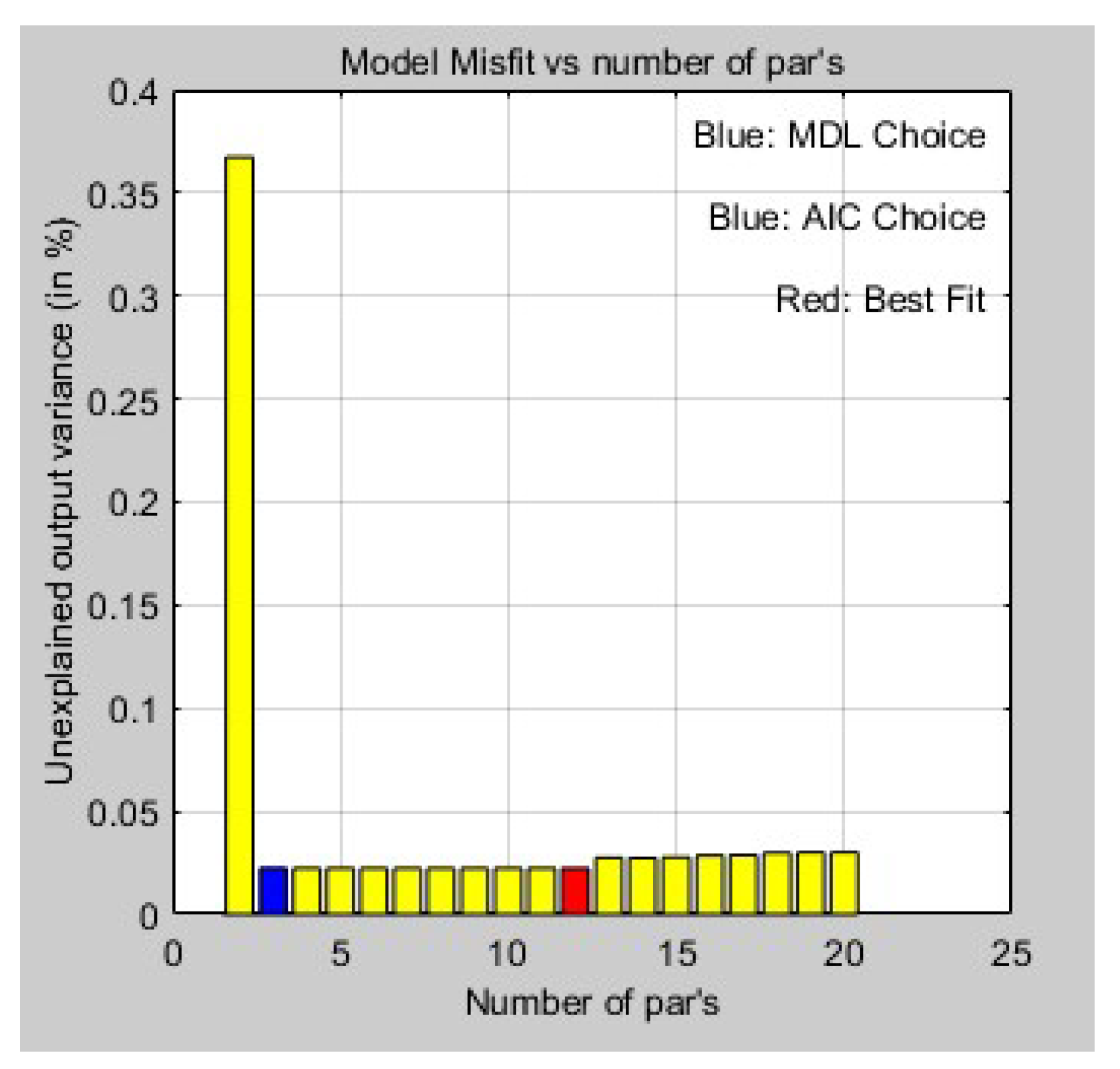
Take the data length of L and the order is taken as n a = 1 , n b = 1 , i = The least square estimation is carried out one by one to obtain the sum of squares of residuals, that is, the loss function J n a + n b . Find the n ^ a and n ^ b corresponding to the minimum F P E n a , n b according to the above equation, that is, the model order required for identification. The data processing results of this experiment are shown in Figure 8. The ordinate is the output variance, and the abscissa is the number of pars. Among them, blue is the best AIC selection, and red is the highest fitting AIC; select the best model order as n a = 2 , n b = 1 , and its misfit value is 0.022515.

2.2.4. Selection of Identification Criterion Function

The criterion function generally selects the sum of squares of the error function, and the error function can be output error, input error or generalized error. Therefore, the error criterion function is divided into output error criterion and input error criterion. Due to the high uncertainty of the complex hydraulic system, the error analysis using generalized error has high accuracy. In this paper, the generalized error criterion is used [30,31], and its error is defined as:
ε ( k ) = S 2 1 [ z ( k ) ] S 1 [ u ( k ) ]
where s 1 , s 2 1 is a generalized model and model s 2 is reversible. This error is defined as generalized error, of which the most commonly used is equation error. For difference equations, s 1 is B q 1 = b 1 z 1 + b 2 z 2 + + b m z m , s 2 1 is A z 1 = 1 + a 1 z 1 + + a n z n . Then the equation error is:
ε ( k ) = A z 1 z ( k ) B z 1 u ( k )
Then error criterion function of the equation can be obtained as:
J ( θ ) = k = 1 N [ A z 1 z ( k ) B z 1 u ( k ) ] 2

2.2.5. Least Squares Identification

The least squares estimation method is a standard method to obtain approximate solutions by regression analysis for over determined systems; that is, there are more equations than unknowns. In this entire solution, the least squares method is calculated as the result of each equation, minimizing the sum of the squares of the residuals.
The mathematical model of time invariant single input single output dynamic process is:
A z 1 z ( k ) = B z 1 u ( k ) + e ( k )
Then, consider the identification problem of model Equation (16), that is, the parameter estimation of θ . As can be seen from the previous section, the selected criterion function is:
J ( θ ) = k = 1 L [ e ( k ) ] 2 = k = 1 L [ z ( k ) h T ( k ) θ ] 2 = z L H L θ T z L H L θ
The method of obtaining the parameter estimate θ ^ L S by minimization Equation (17) is called the least squares method, and θ ^ L S is called the least squares estimate [32].
The experimental data are estimated by the least square method. The result shows that the coincidence between the identified results and the actual values is 72.76%, the FPE value is 2.72343 × 10⁻⁸, and the identified transfer function is:
T F = 0.00159 s + 0.01146 s 2 + 0.01215 s + 9.143
According to the analysis in Section 2, the transfer function of this system is a typical second-order system, which is consistent with the system order established by the mathematical model of the hydraulic system in Section 2; therefore, it meets the expectations of system identification. The transfer function obtained by this method can more accurately represent the actual situation of the system in the actual work, and establish a good foundation for the subsequent establishment of the control system and the determination of the control system parameters.

2.3. Optimization of Closed Loop Servo Control of FBP

At present, the hydraulic multi-stage pressure source FBP, as is the case with most hydraulic machines, adopts the open-loop control mode based on position detection of the slide block. However, the open-loop control only considers the simple corresponding relationship between output and input, but does not consider the influence of system dynamic characteristics and external interference. Therefore, once the output deviation occurs, it cannot be compensated, and the control accuracy cannot meet the operation requirements of the multi-stage pressure source FBP.

2.3.1. Multi-Stage PID Control Technology

As the slide block of the 12,000 kN multi-stage pressure source FBP’s work is divided into different stages, the system characteristics of each operation stage are quite different, and the stage division is strictly determined by the slide block position and the displacement of the slide block is not a strict time function. In industrial process control, the control system is controlled according to the proportion, integral and differential of the error caused by the comparison between the real-time data collected from the controlled object and the given value, which is referred to as the PID (Proportional Integral Derivative) control system. PID control has the advantages of having a simple principle, strong robustness and a wide range of applications. It is a mature technology and the most widely used control system. For the hydraulic system to be controlled in this experiment, the control variable is the input electrical signal of the servo proportional valve, and the measurement process variable is the motion of the slide block, so PID control is very suitable for this hydraulic control system with feedback. Moreover, the hydraulic control system belongs to the valve pump joint control, in which the fast loop is controlled by hydraulic pump which is controlled by the servo motor. The main blanking loop is controlled by the servo valve, they have different system characteristics. Therefore, the conventional PID control is not fully suitable for the operation control of the hydraulic FBP. Based on the operation characteristics of the hydraulic FBP, a multi-stage PID control strategy is proposed in this paper.
In order to accurately describe the different stages of the multi-stage pressure source FBP operation, first define the stage eigenvector Ks = [kFA, kDT, kBL, kFR]: assuming SN = FA, DT, BL, FR (the same below), kSN = 1 indicates that it is in the SN stage, and kSN = 0 indicates that it is in the non-SN stage. The values of the vector Ks in different stages are shown in Table 2.
The multi-stage PID control strategy of the electro-hydraulic system of the large tonnage hydraulic multi-stage pressure source FBP is shown in Figure 9.

2.3.2. Establishment of Simulation Model and PID Parameter Tuning

In Simcenter AMESim, a simulation model of a multi-stage PID control is built according to the control strategy shown in Figure 9, by using the signal library components. Among them, the value of the stage eigenvector is built by Statechart tool. The multi-stage PID control simulation model is shown in Figure 10.
The core problem of the PID controller design is how to adjust the PID parameters; that is, determine the size of K p , K i and K d according to the system characteristics of the controlled object.
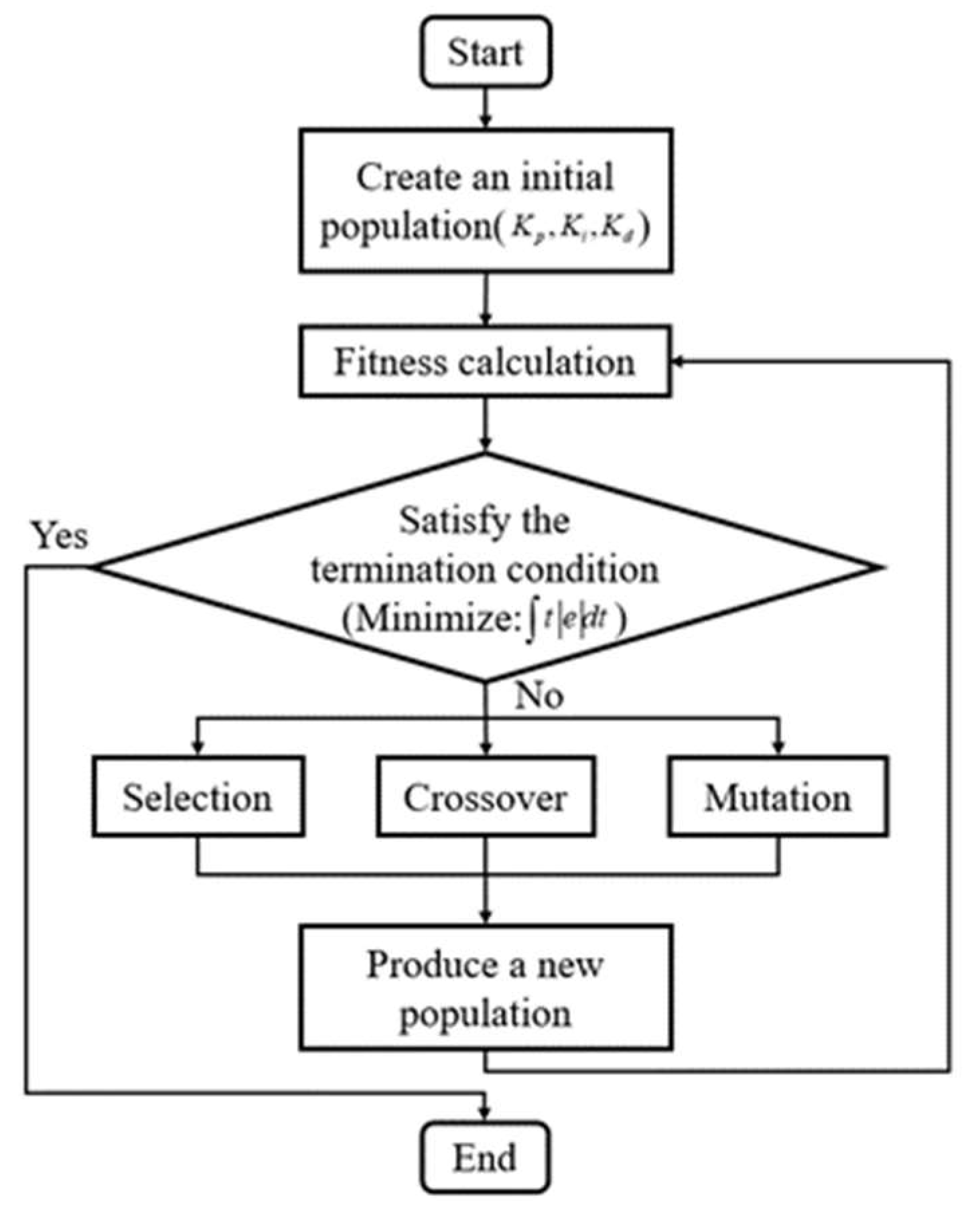
In this paper, the genetic algorithm (Figure 11) is used to realize the PID parameter tuning [33]. To obtain the optimal K p , K i and K d using the genetic algorithm, first set the value range of K p , K i and K d . Then, set the desired optimization goal, that is, to minimize the slider motion deviation, in order to make the slider motion as consistent as possible with the expected. Before genetic algorithm parameter optimization, set the initial K p , K i and K d value as the first generation, and then perform the genetic algorithm optimization calculation. Crossover, selection, and mutation are performed for each generation, and the optimal K p , K i and K d of every generation are obtained repeatedly in this optimization process. First, define the optimization problem:
Find :                                                                 K p ,       K i ,       K d Minimize :                                           t e d t S . T .                                                                   K p L K p K p H ,       K i L K i K i H ,     K d L K d K d H
where K p L and K p H , K i L and K i H , K d L and K d H are the upper and lower limits of K p , K i and K d . Then, the genetic algorithm tool of AMESim is used to solve the above optimization problems, and the PID parameter tuning can be realized.
The above processes are applied to the PID parameter tuning in the FA, DT, BL and FR stages, respectively. In the process of parameter optimization, the engineering setting of the empirical equation is carried out for the PID parameters, and the possible value range of the best PID parameters is determined accordingly. The upper and lower limits of the PID control parameters in the four stages are selected, as shown in the Table 3.
The optimal PID parameters in each stage are obtained after optimization through the genetic algorithm, as shown in the Table 4.

3. Results

3.1. Results and Analysis of Multi-Stage PID Control

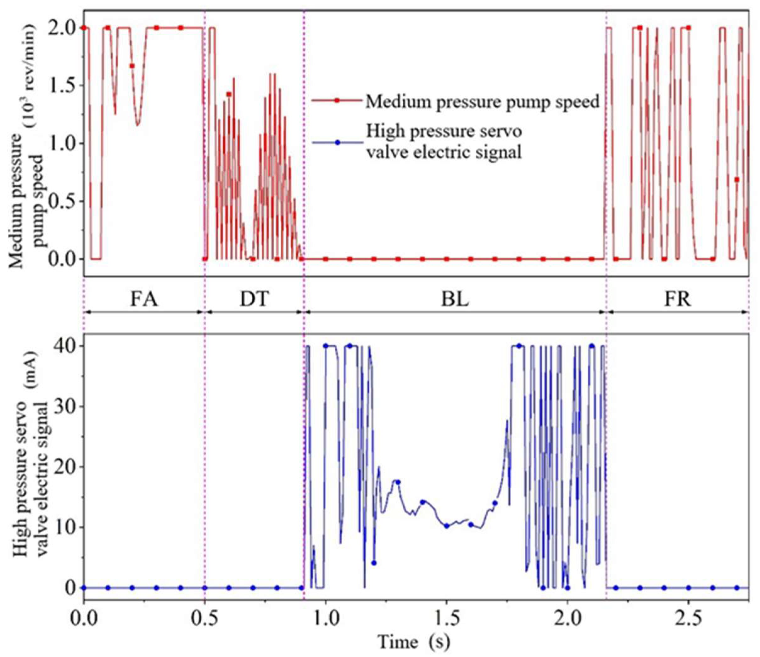
When the multi-stage PID closed-loop servo control is adopted, the speed of the medium pressure pump (P1 in Figure 1) and the input electrical signal of the high-pressure servo valve (YB1 in Figure 1) are shown in Figure 12. The control system regulates the speed of the medium pressure pump in the FA, DT and FR stages, and the speed of the medium pressure pump in the BL stage is 0. The high-pressure servo valve opens and regulates the system only in the BL stage.
The response characteristics of the PID control in the FA stage are shown in Figure 13. As can be seen from the transient response characteristics in Figure 13a, the transient response setting time is 0.13 s and the overshoot is 4.83%, indicating that the transient characteristics of the control system are good. From the steady-state response characteristics in Figure 13b, it can be seen that the steady-state error is basically maintained between −0.5% and 0.1%, indicating that the control system has excellent steady-state characteristics.
The response characteristics of the PID control in the DT stage are shown in the Figure 14. The transient response setting time is 0.05 s and there is no overshoot in the transient process. The system response is rapid and stable, and the steady-state error is basically maintained within ±0.3%. The control system has good steady-state characteristics.
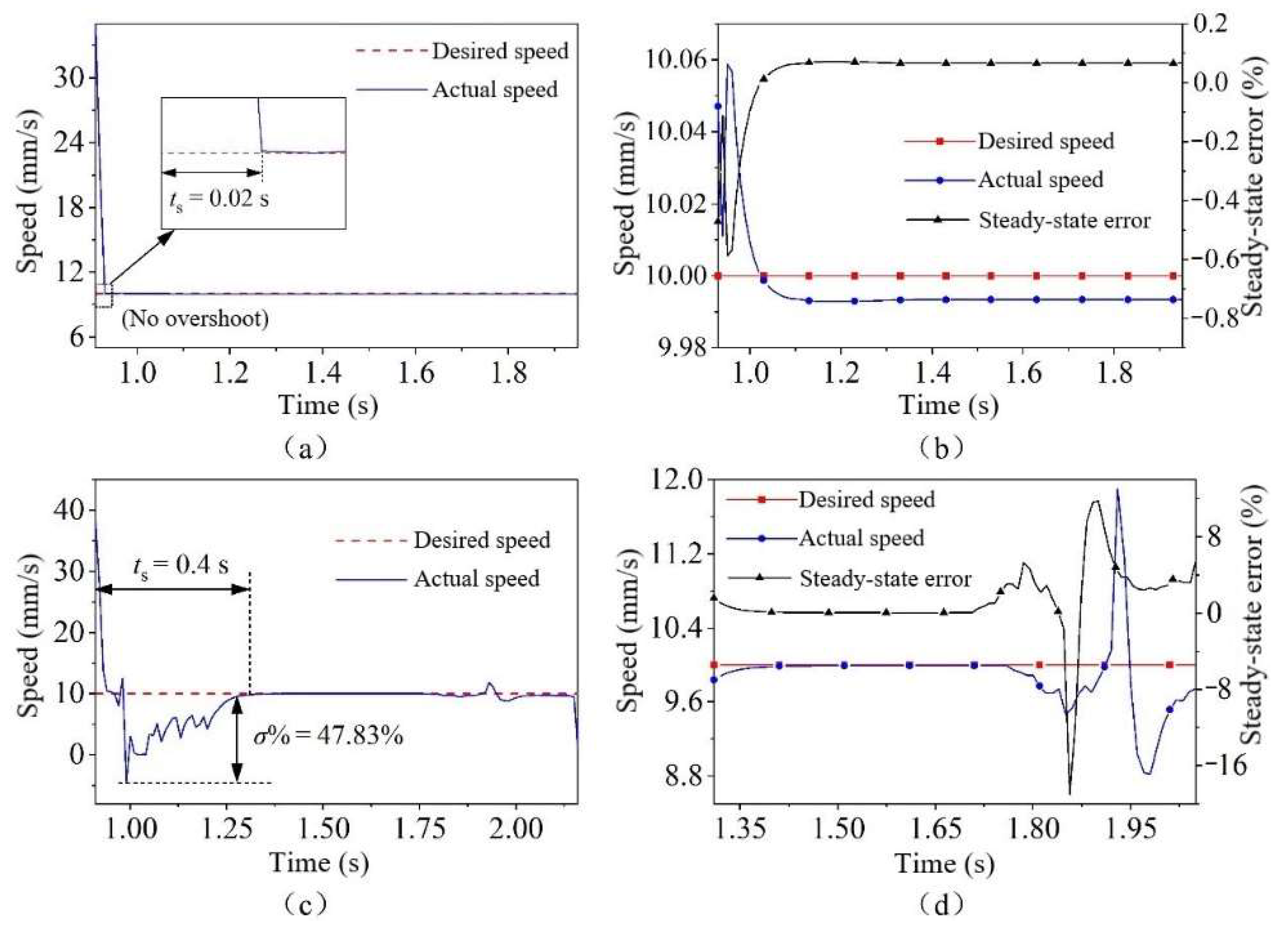
The response characteristics of the PID control in the BL stage are shown in Figure 15. Under the no-load condition, the transient response should be adjusted for only 0.02 s, without overshoot. After reaching the steady state, the steady-state error is maintained within 0.1%. The control system has very good transient response and steady-state response characteristics. However, under the condition of blanking, due to the sudden increase and drastic change in load at the initial stage of the BL, the setting time of the transient response is extended to 0.4 s, and the overshoot reaches 47.83%. After reaching the steady state, the sudden change in load caused by blanking unloading, ejector, unloading and other factors leads to a large speed fluctuation of the slide block within 1.85 s to 2 s [34], so the steady-state error exceeds ±5%. At the maximum, it reaches −18.99% (t = 1.93 s). Therefore, although the control parameters have been optimized, the response characteristics of the PID control in the BL stage need to be further improved under the condition of FB load force.
The response characteristics of the PID control in the FR stage are shown in Figure 16. The transient response setting time is 0.15 s and the response is rapid. However, the overshoot is large (61.95%), which is caused by the small oil pressure in the lower chamber of the fast subsystem oil cylinder at the early stage of the FR stage. The backpressure has not been established, and the slide block falls rapidly under the action of gravity, resulting in a large overshoot. After the system response enters the steady state, the steady-state error is maintained within ±0.1%. However, from t = 2.45 s, due to the influence of the movement of the work piece ejected by the reverse piston, the speed of the slide block fluctuates, and the error reaches the maximum of −6.56% at t = 2.49 s, and the error returns to and remains within ±2% until t = 2.52 s.
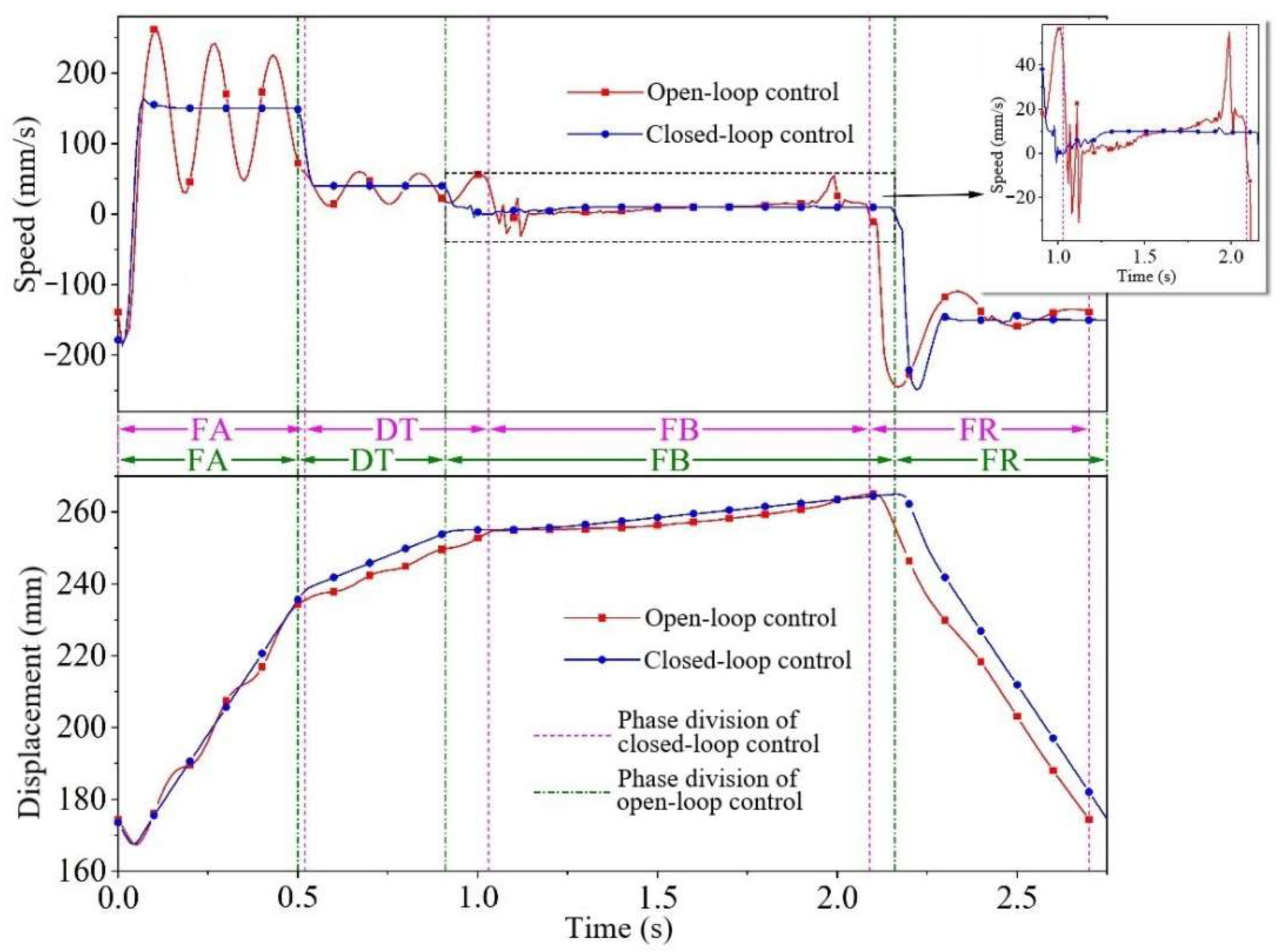
Figure 17 shows the comparison of the simulation results between the open-loop control and multi-stage PID closed-loop servo control. In the FA, DT and FR stages, the speed of the slide block significantly fluctuates when the using open-loop control, and cannot be stable. When using the closed-loop control, the speed of the slide block can quickly reach a stable state. In the BL stage, when the open-loop control is adopted, the speed of the slide block fluctuates significantly. Under the influence of oil hydraulic shrinkage, the speed of the slide block shows a change trend from small to large. The speed suddenly increases during the final unloading. When the closed-loop control is adopted, the blanking speed is relatively stable and can better track the ideal speed curve. It can also be seen from the displacement comparison curve that the displacement curve of the slide block fluctuates greatly in the open-loop control, while the displacement curve of the slide block is stable in the closed-loop control.
To summarize, for the system after energy-saving transformation, if the traditional open-loop control is adopted, the slide block movement speed and displacement fluctuate greatly, which cannot meet the requirements of the FB process. Using the multi-stage PID control method proposed in this paper, the slide block can better track the ideal speed curve and move smoothly. At the same time, in the case of FB load force interference, the response characteristics of the PID control in the BL stage need to be further improved.

3.2. Research on Fuzzy Adaptive PID Control in Blanking Stage

In the BL stage, the FB forming force is large and changes violently, and the load curves are quite different when machining different parts, so it is difficult to control the motion of the slide block. Under no-load and load conditions, the PID control effect of the BL stage is completely different.
For the BL stage with complex working conditions and time-varying system, the motion control of the slide block is difficult and requires high precision. Therefore, when designing the electro-hydraulic control system of the hydraulic FB, it is necessary to further optimize the motion control of the slide block in the BL stage.

3.2.1. Design of Fuzzy Adaptive PID Controller in Blanking Stage

Figure 18 shows the principle of the fuzzy adaptive PID control. It can be seen that this control mode is the combination of fuzzy control and traditional PID control. In essence, it is still PID control, and the fuzzy controller is used to adaptively transform the traditional PID control and realize the real-time adaptive adjustment of the PID control parameters [35].
For fuzzy adaptive PID control, the PID control law is:
u ( t ) = ( K p 0 + Δ K p ) e ( t ) + ( K i 0 + Δ K i ) 0 t e ( t ) d t + ( K d 0 + Δ K d ) d e ( t ) d t
The key to the design of the fuzzy adaptive PID controller lies in the selection of the fuzzy controller, the definition of the input-output fuzzy set and universe, the equation of the fuzzy control rules, the selection of the fuzzy reasoning method and the selection of the membership function.
This paper adopts the double input and three output fuzzy controller; that is, the error e and error change e c are selected as the input variables of the fuzzy controller, and the control quantities Δ K P , Δ K i and Δ K d are selected as the output variables of the fuzzy controller.
The fuzzy language variables of e , e c , Δ K P , Δ K i and Δ K d are {NB, NM, NS, ZE, PS, PM and PB}, which belong to fuzzy sets {negative large, negative medium, negative small, zero, positive small, positive medium and positive large}. According to the mathematical model of the BL stage obtained by system identification (Equation (18)) and the fuzzy PID engineering setting method, the fuzzy subset domains of e , e c , Δ K P , Δ K i and Δ K d are shown in Table 5.
The fuzzy control rules of Δ K P , Δ K i , Δ K d are shown in Table 6, Table 7 and Table 8.
The Mamdani fuzzy reasoning method is selected for fuzzy reasoning in this paper [36]. In addition, the triangular membership function and the center of gravity method are used for inverse fuzzification.

3.2.2. Simulation Analysis of Fuzzy Adaptive PID Control in BL Stage

The models of the controlled system (i.e., the mechanical hydraulic system of the hydraulic multi-stage pressure source FBP) and the PID control are built in Simcenter AMESim, and the fuzzy controller is built in Simulink. The model adaptive PID control simulation in the BL stage is completed in a joint way. The joint simulation model is shown in Figure 19.
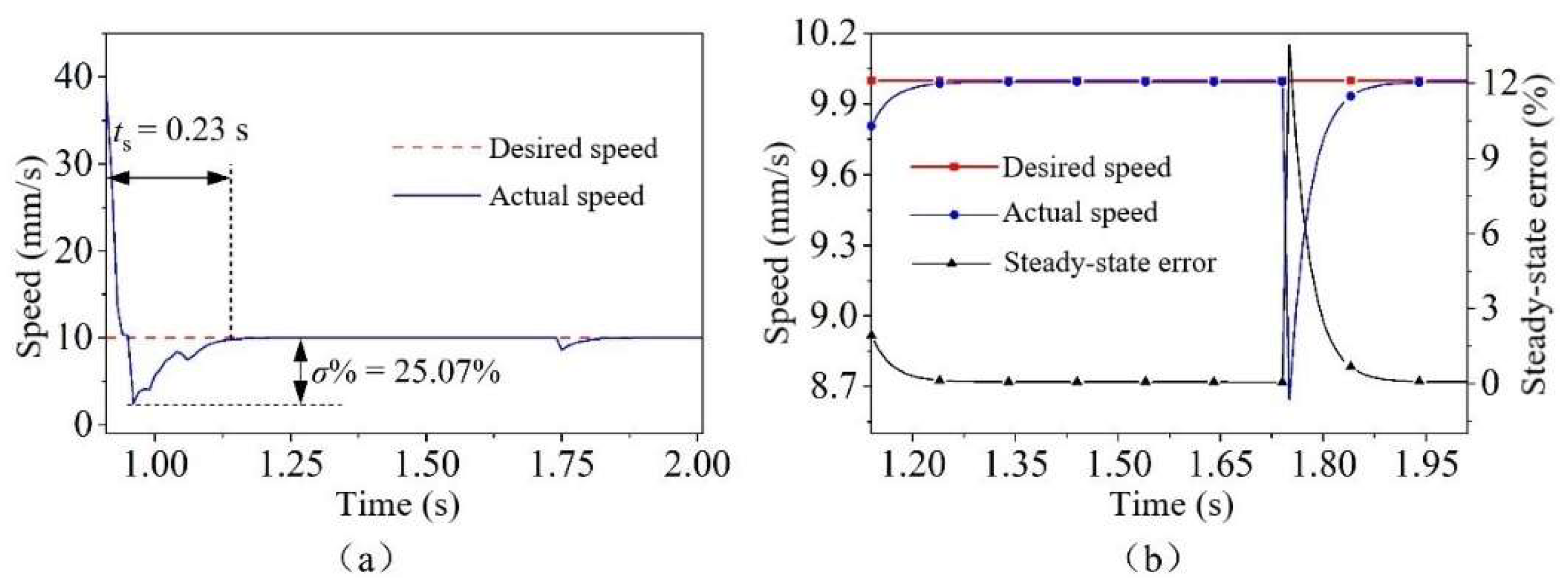
After adopting the fuzzy adaptive PID control, the response characteristics of the BL stage are shown in Figure 20. It can be seen from the transient response characteristics in Figure 20a that the setting time of the transient response is 0.23 s, which is 42.5% less than that of the transient response in the ordinary PID control (0.4 s). The maximum overshoot is 25.07%, which is 47.31% less than the maximum overshoot (47.83%) controlled by the ordinary PID. As can be seen from Figure 20b, the steady-state response characteristics of the fuzzy PID control are also improved compared with the ordinary PID control.

4. Discussion

The control effects of the different stages and control methods are shown in the Table 9. The control results show that the slide block motion accuracy of FBP is higher, and the control effect is very obvious after using the multi-stage PID control. This effectively reduces the stability time, overshoot and steady-state error of each stage. At the same time, for the BL stage with variable load conditions, the fuzzy PID control is also very effective in improving the stability and dynamic performance of the system. Therefore, the control mode proposed in this paper is feasible.

5. Conclusions

In this paper, the problems of slide block speed fluctuation, low motion accuracy and serious system vibration of the multi-stage pressure source FBP are studied. The conclusions are as follows:
(1)
The hydraulic system of the multi-stage pressure source FBP is introduced, and the mathematical model for the valve-controlled cylinder system is established.
(2)
The system identification experiment method, using the least square method, is proposed, and the more accurate transfer function of the valve control cylinder system in the BL stage of the hydraulic multi-stage pressure source FBP is obtained.
(3)
A multi-stage PID control method is proposed, and the fuzzy PID control method is used alone in the BL stage to effectively improve the motion accuracy of the slide block. The speed fluctuation of the slide block and the impact vibration of the hydraulic system are effectively reduced. The machining accuracy of the multi-stage pressure source FBP is improved, and its service wear is reduced.

Author Contributions

Put forward ideas and conducted 80% of the tests, Y.S.; Provide experimental equipment and conducted 20% of the tests, Y.L.; Established the controller and simulated, X.Z.; Conducted experiments, Z.X. and M.C. All authors have read and agreed to the published version of the manuscript.

Funding

This research was funded by the National Key R&D Program of China (No. 2020YFA0714900) and the National Natural Science Foundation of China (No. 52275371).

Data Availability Statement

The data presented in this study are available on request from the corresponding author.

Acknowledgments

The authors are grateful for the financial supports from the National Key R&D Program of China (No. 2020YFA0714900) and the National Natural Science Foundation of China (No. 52275371).

Conflicts of Interest

The authors declare no conflict of interest. The sponsors had no role in the design, execution, interpretation, or writing of the study.

References

  1. Aravind, U.; Chakkingal, U.; Venugopal, P. A Review of Fine Blanking: Influence of Die Design and Process Parameters on Edge Quality. J. Mater. Eng. Perform. 2020, 30, 1–32. [Google Scholar] [CrossRef]
  2. Daeizadeh, V.; Elyasi, M. Research on influence of material properties and blank geometry on forming force in fine blanking process. Mater. Res. Innov. 2011, 15, S370–S372. [Google Scholar] [CrossRef]
  3. Fan, W.F.; Li, F. Study on Blanking Force of Fine-blanking with Negative Clearance and Common Blanking for AISI-1045 through Simulation and Experiment Methods. Mater. Sci. Forum 2012, 704, 1175. [Google Scholar] [CrossRef]
  4. Thipprakmas, S. Improving wear resistance of sprocket parts using a fine-blanking process. Wear 2011, 271, 2396–2401. [Google Scholar] [CrossRef]
  5. Xu, B.; Shen, J.; Liu, S.H.; Su, Q.; Zhang, J.H. Research and Development of Electro-hydraulic Control Valves Oriented to Industry 4.0: A Review. Chin. J. Mech. Eng. 2020, 33, 29. [Google Scholar] [CrossRef] [Green Version]
  6. Zhao, X. System Design, Analysis and Optimization of Heavy-Load Hydraulic Fine-Blanking Press. Ph.D. Thesis, Wuhan University of Technology, Wuhan, China, 2021. [Google Scholar]
  7. Gu, Z.Q.; Chen, M.Z.; Wang, C.Y.; Zhuang, W.H. Static and Dynamic Analysis of a 6300 KN Cold Orbital Forging Machine. Processes 2021, 9, 7. [Google Scholar] [CrossRef]
  8. Ji, Y.; Wang, H.; Chen, H.Q.; Guo, M.X. Research on Hydraulic Speed Control System of Ship Crane Anti-Rolling Device. IOP Conf. Ser. Earth Environ. Sci. 2019, 295, 042130. [Google Scholar] [CrossRef]
  9. Zhang, F. Design of Hydraulic Control System for Press Machine and Analysis on Its Fluid Transmission Features. Int. J. Heat Technol. 2021, 39, 161–169. [Google Scholar] [CrossRef]
  10. Shen, W.; Wang, J.H. A robust controller design for networked hydraulic pressure control system based on CPR. Peer Peer Netw. Appl. 2019, 12, 1651–1661. [Google Scholar] [CrossRef]
  11. Neha, T.; Kuldeep, K.S. Tuning of PID Controller using PSO and ITS Performances on Electro-Hydraulic Servo System. Int. J. Mod. Trends Eng. Res. 2015, 2, 233–235. [Google Scholar]
  12. Samakwong, T.; Assawinchaichote, W. PID Controller Design for Electro-hydraulic Servo Valve System with Genetic Algorithm. Procedia Comput. Sci. 2016, 86, 91–94. [Google Scholar] [CrossRef]
  13. Liu, Z.; Gao, Q.; Niu, H. The Position Control of the Hydraulic Cylinder Controlled by the High-Speed On-off Valve. Sens. Transducers 2013, 160, 590–601. [Google Scholar]
  14. Bing, X.; Jian, Y.; Yang, H.Y. Comparison of energy-saving on the speed control of the VVVF hydraulic elevator with and without the pressure accumulator. Mechatronics 2005, 15, 1159–1174. [Google Scholar] [CrossRef]
  15. Jiang, W.G.; Zhang, C.; Jia, P.S.; Yan, G.S.; Ma, R.; Chen, G.X.; Ai, C.; Zhang, T.G. A Study on the Electro-Hydraulic Coupling Characteristics of an Electro-Hydraulic Servo Pump Control System. Processes 2022, 10, 1539. [Google Scholar] [CrossRef]
  16. Zhang, F.; Zhang, J.H.; Cheng, M.; Xu, B. A Flow-Limited Rate Control Scheme for the Master-Slave Hydraulic Manipulator. IEEE Trans. Ind. Electron. 2022, 69, 4988–4998. [Google Scholar] [CrossRef]
  17. Guo, Y.Q.; Zha, X.M.; Shen, Y.Y.; Wang, Y.N.; Chen, G. Research on PID Position Control of a Hydraulic Servo System Based on Kalman Genetic Optimization. Actuators 2022, 11, 162. [Google Scholar] [CrossRef]
  18. Maier, C.C.; Schroders, S.; Ebner, W.; Koster, M.; Fidlin, A.; Hametner, C. Modeling and nonlinear parameter identification for hydraulic servo-systems with switching properties. Mechatronics 2019, 61, 83–95. [Google Scholar] [CrossRef]
  19. Jiang, X.P.; Wang, Z.T.; Zhu, H.; Wang, W.S. Hydraulic turbine system identification and predictive control based on GASA-BPNN. Int. J. Miner. Metall. Mater. 2021, 28, 1240–1247. [Google Scholar] [CrossRef]
  20. Tian, T.; Zhao, W.; Zhen, W.X.; Liu, C.Y. Application of Improved Whale Optimization Algorithm in Parameter Identification of Hydraulic Turbine at No-Load. Arab. J. Sci. Eng. 2020, 45, 9913–9924. [Google Scholar] [CrossRef]
  21. Feng, H.; Yin, C.B.; Ma, W.; Yu, H.F.; Cao, D.H. Parameters identification and trajectory control for a hydraulic system. ISA Trans. 2019, 92, 228–240. [Google Scholar] [CrossRef]
  22. Wang, J.P.; Huang, G.M.; Lee, H.D.; Chen, C.C.; Chen, T.T.; Chen, C.L. Optimization of Fine Hydro-Blanking. Steel Res. Int. 2013, 84, 777–783. [Google Scholar] [CrossRef]
  23. Sun, J.W.; Zhao, K. Adaptive neural network sliding mode control for active suspension systems with electrohydraulic actuator dynamics. Int. J. Adv. Robot. Syst. 2020, 17, 1729881420941986. [Google Scholar] [CrossRef]
  24. Grosschmidt, G.; Harf, M. Multi-pole modeling and simulation of an electro-hydraulic servo-system in an intelligent programming environment. Int. J. Fluid Power 2016, 17, 1–13. [Google Scholar] [CrossRef]
  25. Paszota, Z. Mathematical Model Defining Volumetric Losses of Hydraulic Oil Compression in a Variable Capacity Displacement Pump. Pol. Marit. Res. 2014, 21, 90–99. [Google Scholar] [CrossRef] [Green Version]
  26. Bellman, R.; Kagiwada, H.; Kalaba, R. Quasilinearization, system identification and prediction. Int. J. Eng. Sci. 1965, 3, 327–334. [Google Scholar] [CrossRef]
  27. Li, W.F.; Liao, Q.; Xu, M.J.; Li, X.H.; Liu, S.W. Prestressed Tension Hydraulic System Identification Using Linear Programming Support Vector Regression. In Proceedings of the 2016 International Congress on Computation Algorithms in Engineering, Bangkok, Thailand, 19–21 October 2016; pp. 188–192. [Google Scholar]
  28. Stojanovic, V.; Nedic, N.; Prsic, D.; Dubonjic, L. Optimal experiment design for identification of ARX models with constrained output in non-Gaussian noise. Appl. Math. Model. 2016, 40, 6676–6689. [Google Scholar] [CrossRef]
  29. Arnold, T.W. Uninformative Parameters and Model Selection Using Akaike’s Information Criterion. J. Wildl. Manag. 2010, 74, 1175–1178. [Google Scholar] [CrossRef]
  30. Inatsu, Y.; Imori, S. Model selection criterion based on the prediction mean squared error in generalized estimating equations. Hiroshima Math. J. 2018, 48, 307–334. [Google Scholar] [CrossRef]
  31. Michael, P.J.A. Test for Comparing Estimators under the Generalized Mean Square Error Criterion. J. R. Stat. Soc. Ser. B Methodol. 1984, 46, 284–295. [Google Scholar] [CrossRef]
  32. Zinger, A.A.; Kagan, A.M. A Least Squares Estimate, Nonquadratic Losses, and Gaussian Distributions. Theory Probab. Its Appl. 2006, 36, 115–123. [Google Scholar] [CrossRef]
  33. Shao, L.; Liu, N.; Zuo, H. The Research on Temperature Control System of Heat Transfer Station Based on Genetic Algorithm PID Control. Appl. Mech. Mater. 2013, 2635, 433–436. [Google Scholar] [CrossRef]
  34. Mao, H.J.; Zhou, F.; Liu, Y.X.; Hua, L. Numerical and experimental investigation of the discontinuous dot indenter in the fine-blanking process. J. Manuf. Process. 2017, 24, 90–99. [Google Scholar] [CrossRef]
  35. Xia, C.G.; Cao, C. Tuning of PID Parameters and Fuzzy Adaptive PID Control of the Hydrostatic Driving System. Adv. Mater. Res. 2012, 403, 5112–5116. [Google Scholar] [CrossRef]
  36. Pourjavad, E.; Mayorga, R.V. A comparative study and measuring performance of manufacturing systems with Mamdani fuzzy inference system. J. Intell. Manuf. 2019, 30, 1085–1097. [Google Scholar] [CrossRef]
Figure 1. The physical simulation model of the main system of 12,000 kN hydraulic multi-stage pressure source FBP.
Processes 11 00059 g001
Figure 2. Valve controlled cylinder system model.
Processes 11 00059 g002
Figure 3. The hydraulic cylinder controls the slide block movement in the BL stage.
Processes 11 00059 g003
Figure 4. Basic steps of system identification.
Processes 11 00059 g004
Figure 5. FB production line and data acquisition.
Processes 11 00059 g005
Figure 6. Input and output signals of system identification experiment: (a) ideal input signal; (b) actual input signal; (c) actual output.
Processes 11 00059 g006
Figure 7. Black box structure of SISO process ARX model.
Processes 11 00059 g007
Figure 8. Experimental results of order selection of system model.
Processes 11 00059 g008
Figure 9. Multi-stage PID control strategy for electro-hydraulic system of multi-stage pressure source FBP.
Processes 11 00059 g009
Figure 10. Multi-stage PID control simulation model of 12,000 kN multi-stage pressure source FBP.
Processes 11 00059 g010
Figure 11. Flowchart of the genetic algorithm.
Processes 11 00059 g011
Figure 12. The multi-stage PID controls the speed of the medium pressure pump and the electric signal of the high-pressure servo valve.
Processes 11 00059 g012
Figure 13. Response characteristics of PID control in FA stage: (a) Transient response characteristics; (b) Steady state response characteristics.
Processes 11 00059 g013
Figure 14. Response characteristics of PID control in DT stage: (a) Transient response characteristics; (b) Steady state response characteristics.
Processes 11 00059 g014
Figure 15. Response characteristics of PID control in BL stage: (a) Transient response characteristics under no-load; (b) Steady state response characteristics at no load; (c) Transient response characteristics during BL; (d) Steady state response characteristics during BL.
Processes 11 00059 g015
Figure 16. Response characteristics of PID control in FR stage: (a) Transient response characteristics; (b) Steady state response characteristics.
Processes 11 00059 g016
Figure 17. Comparison of motion (velocity and displacement) curves between open-loop control and closed-loop control.
Processes 11 00059 g017
Figure 18. Fuzzy adaptive PID control principle.
Processes 11 00059 g018
Figure 19. Joint simulation modeling of fuzzy PID control in BL stage.
Processes 11 00059 g019
Figure 20. Response characteristics of fuzzy adaptive PID control in BL stage: (a) Transient response characteristics; (b) Steady state response characteristics.
Processes 11 00059 g020
Table 1. Hardware models of the system.
Hardware NameSpecification
PLCS7-1200
HMI human-machine interactionKTP1200
Proportional servo valve4WRL16V1-120M-3X/G24Z4/M
Pressure sensorHUBA511.943003742
Displacement sensorBTL7-V50T
Table 2. Value of stage eigenvector Ks.
FADTBLFR
kFA1000
kDT0100
kBL0010
kFR0001
Table 3. Four stage PID parameter optimization value range.
FADTBLFR
[KpL, KpH][0, 2000][0, 2000][0, 2000][0, 5000]
[KiL, KiH][0, 500][0, 200][0, 200][0, 200]
[KdL, KdH][0, 50][0, 100][0, 50][0, 400]
Table 4. PID parameters adjusted by genetic algorithm.
FADTBLFR
K p 555.901673.301770.9071.47
K i 116.2176.600.0160.27
K d 29.0824.3249.8390.59
Table 5. Fuzzy subset domains of fuzzy variables.
NBNMNSZEPSPMPB
e −0.6−0.4−0.200.20.40.6
e c −0.3−0.2−0.100.10.20.3
Δ K P −60−40−200204060
Δ K i −0.006−0.004−0.00200.0020.0040.006
Δ K d −6−4−20246
Table 6. The fuzzy control rules of Δ K P .
Δ K P e c
NBNMNSZEPSPMPB
e NBPBPBPMPMPSZEZE
NMPBPBPMPSPSZENS
NSPMPMPMPSZENSNS
ZEPMPMPSZENSNMNM
PSPSPSZENSNSNMNM
PMPSZENSNMNMNMNB
PBZEZENMNMNMNBNB
Table 7. The fuzzy control rules of Δ K i .
Δ K i
e c
NBNMNSZEPSPMPB
e NBNBNBNMNMNSZEZE
NMNBNBNMNSNSZEZE
NSNBNMNSNSZEPSPS
ZENMNMNSZEPSPMPM
PSNMNSZEPSPSPMPB
PMZEZEPSPSPMPBPB
PBZEZEPSPMPMPBPB
Table 8. The fuzzy control rules of Δ K d .
Δ K d
e c
NBNMNSZEPSPMPB
e NBPSNSNBNBNBNMPS
NMPSNSNBNMNMNSZE
NSZENSNMNMNSNSZE
ZEZENSNSNSNSNSZE
PSZEZEZEZEZEZEZE
PMPBNSPSPSPSPSPB
PBPBPMPMPMPSPSPB
Table 9. Control results at different stages.
Phase (Control Method)Transient Response Setting Time (s)Overshoot (%)Steady-State Error (%)
FA (PID)0.134.83%−0.5%~0.1%
DT (PID)0.050±0.3%
BL no-load condition (PID)0.020<0.1%
BL blanking condition (PID)0.447.83%−18.99%
BL (fuzzy adaptive PID)0.2325.07%<0.1%
FR (PID)0.1561.95%±2%
Disclaimer/Publisher’s Note: The statements, opinions and data contained in all publications are solely those of the individual author(s) and contributor(s) and not of MDPI and/or the editor(s). MDPI and/or the editor(s) disclaim responsibility for any injury to people or property resulting from any ideas, methods, instructions or products referred to in the content.