Abstract
Bearings and other revolute pairs in gear drives will form clearances due to wear after working for a long time, which will aggravate the vibration and noise of the gear. Therefore, taking the gear drives with revolute pair clearance as the research object, the calculation formulas of the backlash and contact ratio is derived, and the time-varying mesh stiffness model considering the clearance is presented in this work. Then, a nonlinear dynamic model for the gear drives with revolute pair clearance is proposed by combining the backlash, contact ratio and the time-varying mesh stiffness. The effects of the clearance on the meshing stiffness, load sharing factor and nonlinear behavior are investigated. Results indicate that the revolute pair clearance weakens the meshing stiffness and increases working hours in single teeth contact area, thereby increasing the risk of premature failure of the gear drive. In addition, the revolute pair clearance has negligible effect on the nonlinear behavior of gear pair in low-speed running, but it can obviously change the bifurcation behavior and aggravate the vibration of the gear drive.
1. Introduction
Gears are one of the most important power transmission elements in the aerospace, automotive, robotic, agricultural machinery and other fields. Gear drives are mainly used to transfer torque and speed. As a result, they become the main source of vibration and noise for a lot of equipment. After working for a long time, the bearing in the gear drive will form clearance due to wear, which causes the increase in gear vibration and noise. With the rapid development of new energy vehicles and electric agricultural machinery, the working speed of gear transmission has risen significantly, and the effect of the revolute pair clearance on gear vibration and noise will be more significant. Therefore, it is necessary to investigate the effect of the clearance in rotating pairs on the nonlinear dynamics of gear drives.
Gear dynamics has been studied for about 100 years. In the early stage, the research focused on gear strength and dynamic load. In 1950, Tuplin [1] proposed the mass-spring model for gear meshing. Since then, the research of gear dynamics has changed from impact analysis to vibration analysis. Through the efforts of scholars for more than 30 years, the gear dynamic model has undergone the transformation from linear time-invariant and linear time-varying to nonlinear time-varying dynamic model. As early as in 1985, Mitchell and David [2] discovered that gear transmission is a nonlinear system. However, it was not until the nonlinear dynamics model established by Ozguven et al. [3] and Kahraman et al. [4] based on tooth side clearance was compared and consistent with the experimental results tested by Munro [5] that the gear nonlinear dynamics research entered the stage of rapid development.
Many efforts have been made to study the nonlinear dynamics of gear drives, and the research results were reviewed by Wang et al. [6]. In the early stage, the gear dynamic response is mainly predicted by the single degree of freedom (DOF) dynamics model. Based on the single-DOF gear dynamics model, Vaishya and Singh studied the nonlinear behavior of the gear system by introducing nonlinear friction [7] and periodically varying gear mesh parameters [8]. Tamminana et al. [9] studied the correlation between dynamic load coefficient and dynamic transmission error (DTE) based on the single-DOF dynamic model. Xiao et al. [10] investigated the effects of oil film stiffness and damping on spur gear dynamics based on the single-DOF gear dynamics model. In 1975, Mitchell and Mellen [11] discovered the bending-torsional coupling vibration in high-speed gear transmission, and the demand of multi-directional vibration analysis is becoming more and more obvious. Therefore, the study of gear dynamics is transitioned from single-DOF dynamic model to multi-DOF dynamic model. Walha et al. [12] applied the multi-DOF dynamic model to analyze the dynamic response of a two-stage gear transmission. Gou et al. [13] deduced the expression of meshing stiffness as a function of tooth surface flash temperature based on Hertz contact theory, and studied the influence of tooth surface temperature on gear dynamic behavior. Liu et al. [14] studied the effect of bearing thermal deformation on nonlinear dynamic characteristics of an electric drive helical gear system. Fu et al. [15] established a multi-DOF dynamic model for a two-stage gear transmission and studied the dynamic response in the normal and fault states.
With the higher precision requirement of mechanical equipment, the influence of various errors on the dynamic response of gear has been considered gradually in gear dynamic models. Cao et al. [16] investigated the influence of gear eccentricity caused by manufacturing errors on dynamic performance of a planetary gear train. Then, Wang et al. [17] studied the effect of gear eccentricity and varying load on gear time-varying backlash, and predicted the gear DTE without backlash and with constant backlash and time-varying backlash. Chen et al. [18] acquired the static transmission error of the gear drives by an experiment and analyzed its effect on a crowned gear pair. Pan et al. [19] analyzed the effect of random excitations on gear dynamic response based on a 10-DOF dynamic model. Oğuz and Fatih [20] established a four-DOF dynamic model of gear drives with symmetric and asymmetric tooth profiles, and predicted the DTE of the gear pair. Li and Peng [21] employed the fractal theory to reliably estimate the gear backlash and bearing clearance, and studied the effect of these factors on gear dynamic characteristics. Chao et al. [22] investigated the effect of random tooth profile errors on the dynamic behaviors of gear drives. Zhang et al. [23] investigated the dynamic similarity of gear drives by considering the machining error distortion in theory and experiment. Chen and Tang [24] established the dynamic model of a double-helical gear set with staggering and pitch errors, and studied the effect of these errors on the dynamic response. Tian et al. [25] presented a nonlinear collision model with time-varying contact stiffness/damping for analyzing the effect of bearing collision behaviors.
The above literatures mainly focus on the influence of initial errors such as gear eccentricity, tooth shape error and pitch error on the dynamic performance of gear transmission system. The accumulated errors formed during gear operation will gradually increase the gear vibration and accelerate the failure of the gear transmission system. In view of this topic, researchers paid more attention to the influence of cracks in the early stage, and focused on the mesh stiffness reduction due to tooth root crack [26,27,28,29]. Shao and Chen [30] discovered that the tooth root crack also caused tooth plastic inclination and studied its effect on the displacement excitation, mesh stiffness and load sharing factor in mesh. Jiang et al. [31] established a multi-DOF gear dynamic model and analyzed the effect of tooth profile error caused by spalling defect on the dynamic characteristics of helical gear with friction excitation. Liu et al. [32] studied the interaction between toot surface wear accumulation and gear dynamic performance. Li and Anisetti [33] analyzed the relationship between gear tribo-dynamic response and pitting crack nucleation.
The above literatures mainly focus on the influence of cumulative amounts such as tooth surface wear, pitting erosion and root crack on the dynamic performance of gear pairs. However, bearings and other rotating pairs will form a clearance due to wear after working for a long time, thereby increasing the center distance and backlash and reducing the contact ratio of the gear pair. Few literatures comprehensively analyze the influence of these parameters on gear meshing characteristics and dynamic performance. Therefore, this work aims to establish a dynamic model for the gear drive with revolute pair clearance and reveal the mechanism of the influence of clearance on gear nonlinear dynamics.
The difference from the published papers is that our work considers the following specific interactions: (1) the effect of revolute pair clearance on gear TVMS and load sharing factor; (2) the effect of revolute pair clearance on meshing angle, backlash and contact ratio of the gear pair.
2. Model
The center distance of gear pairs will be changed with the increase in the wear of bearings, which affects the gear meshing stiffness, load sharing factor, meshing angle and backlash. The change of these parameters will lead to different nonlinear dynamic behaviors of gear drives.
2.1. Mesh Stiffness Model
The center distance will increase in the gear pairs with revolute pair clearance. To investigate the effect of the wear clearance of revolute pair on gear dynamics, the error of center distance caused by the manufacturing and assembly is not included, and that caused by the revolute pair clearance is only considered in this work. Thus, the error of center distance is numerically equivalent to the revolute pair clearance, as shown in Figure 1. The meshing angle will be changed, and it can be expressed as:
where, and refer to the base radius of the pinion and gear, respectively. m represents the modules of gear; is the revolute pair clearance; and are the number of teeth of the pinion and gear, respectively. In Figure 1, Oi and ωi represent the rotational center and the angular speed; ri refers to the radius of the reference circle; P refers to the pitch point; Ni represents the intersection of the base circle and LOA; Bi represents the intersection of the addendum circle and LOA; Subscript 1 and 2 represent the pinion and the gear, respectively.
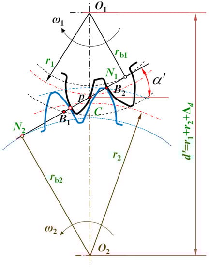
Figure 1.
Schematic diagram of the mesh theory of involute gear pair.
With the increase of the meshing angle, the length of line-of-action also changes, and it can be written as:
where, and are the pressure angle at addendum circle of the pinion and gear, respectively. When the center distance of the gear pair increases, the contact ratio can be obtained by
In addition, backlash will become large with the increase in the center distance of the gear pair. The half of backlash can be written as
where, b0 is the initial half of backlash of the gear pair.
Figure 2 shows the geometrical profile and force diagram of the involute spur gear. AB is the addendum circle. Curve BC is the involute, and Curve CD is the transition curve at tooth root. rf represents the radius of the dedendum circle, and point i refers to the point at which the load is applied; F is the applied load; x and y represent the x-value and y-value of the point of tooth profile, respectively. τ is the angle between x-axis and the line between the rotational center and the tangent point in base circle. ϑ is the angle between x-axis and the line between the rotational center and point C. We can use the potential energy method to calculate the time-varying meshing stiffness (TVMS). The tooth can be equivalent to the cantilever beam consolidated in the tooth root circle [34]. When the teeth loaded a force of F, it will produce contact deformation, bending deformation, shear deformation and compression deformation. In addition, the gear body will also contribute to the tooth deflections [35].
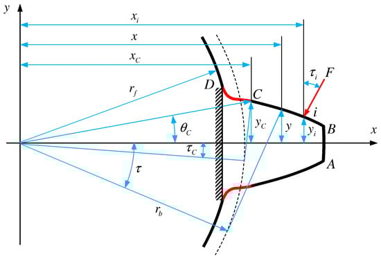
Figure 2.
Geometrical profile and force diagram of the involute spur gear.
The total potential energy of a meshing tooth pair consists of the potential energy caused by contact deformation, bending deformation, shear deformation and compression deformation of tooth and the deformation of fillet-foundation, and it can be written as
where, subscript i = 1,2 represents the pinion and the gear, respectively. Uh, Ua, Ub, Us and Uf are the potential energy caused by contact deformation, compression deformation, bending deformation and shear deformation of tooth and the deformation of fillet-foundation, respectively. is a correction coefficient of the fillet-foundation stiffness, and it can be determined by the finite element method [36]. These potential energy can be presented as
In Equation (6), the contact stiffness kh and the fillet-foundation stiffness kf can be written as
where, E and υ are the elastic modulus and Poisson’s ratio of gear material. B refers to the tooth width. τi is defined as the angle between the force and the y-axis. The parameters u, Sf, L*, M*, P*, Q* is applied to calculate the fillet-foundation stiffness, and they can be referred to Ref. [35]. In Equation (5), the potential energy yields by compression deformation, bending deformation and shear deformation can be expressed as
In Equation (9), and . Fx and Fy represent the component of the force F along the x and y directions, respectively. G is the shear modulus of the gear material. Thus, Equation (9) can be rewritten as
where, ka, kb and ks represent the compression stiffness, bending stiffness and shear stiffness of the toot pair, respectively.
y1 and y2 in the formulas of the area Ax and cross sectional moment of inertia Ix can be seen in Ref. [37]. Combining the Equations (4) and (5), the mesh stiffness of a single tooth pair can be written as
There are single tooth and double teeth mesh areas in the spur gear pair with the contact ratio between one and two. Thus, the time-varying mesh stiffness and load sharing factor of the gear pair can be written as
2.2. Nonlinear Dynamic Model
The gear contact model can be equivalent to the contact between two base cylinders connected by a spring-damping system. The nonlinear dynamic model with six DOF is illustrated in Figure 3. Therefore, the generalized coordinate vector of this system is . Where, xi, yi and ϑi are the displacement in the direction x, y and rotation; kxi and kyi are the bearing stiffness along the direction x and y, respectively; cxi and cyi are the bearing damping along the direction x and y, respectively; Ji is the moment of inertia, and Ti is the torque. rbi is the radius of the base circle, and b represents the half of the backlash. km and cm are the TVMS and the mesh damping, respectively. d is the center distance of the gear pair, and e is the transmission error, respectively. DTE of gear drives reflects the ability of gear to resist deformation along LOA direction. DTE is an important parameters to evaluate the vibration performance of gear drives, and it can be defined as:
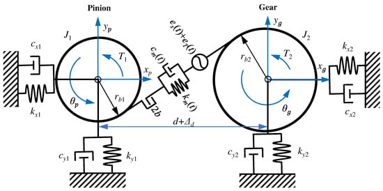
Figure 3.
The nonlinear dynamic model of the gear pair with the center distance error.
The static transmission error is often introduced into gear dynamic models to assess the effect of manufacturing and installation errors [38,39], and it can be defined as:
where, fm represents mesh frequency, and fs is the rotation frequency of the axis. e1 and e2 refer to the amplitudes of the error with the mesh frequency and the error with the rotation frequency of the axis, respectively. φ1 and φ2 represent the corresponding phase angle. Thus, the deformation of the gear pair can be expressed as
Taking the backlash and static transmission error into account, the contact force between the meshing tooth can be written ass
where, cm is the mesh damping between the meshing tooth. The sign functions γm0 and γm1 can be expressed as
Including the gear backlash and center error, the nonlinear dynamic model of the spur gear can be written as the following matrices.
where,
3. Results and Discussion
The basic parameters of the spur gear pair are provided in Table 1. According to the proposed model, the time-varying mesh stiffness, load sharing coefficient and nonlinear behaviors of this gear pair are obtained. To analyze the effect of the clearance in revolute pair on the dynamic characteristics of gear pair, the predicted results with the clearances of 0.3 mm and 0.6 mm are compared with that without clearance.

Table 1.
Basic parameters of the gear pair.
3.1. Mesh Stiffness and Load Sharing Factor
Due to the existence of the clearance in the revolute pair, there are various changes in the meshing angle and the contact ration of the gear pair, which has a considerable effect on the TVMS of the gear pair, as shown in Figure 4a. The length of the LOA of the gear pair decreases with the increase of the clearance in the revolute pair, thereby greatly reducing the contact ratio of the gear pair. When the clearance in the revolute pair becomes large, the TVMS of the gear pair decreases in the single teeth contact area and double tooth contact area. The RMS value of the TVMS in a mesh cycle decreased from 399.4 N/μm to 384.5 N/μm.
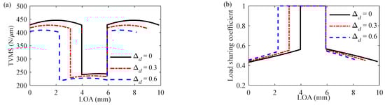
Figure 4.
TVMS and Load sharing factor: (a) TVMS and (b) Load sharing coefficient.
In addition, with the increase of the clearance in the revolute pair, the position of the lowest point of the single teeth contact area moves down obviously, and the single teeth contact area increases. The contact stress and root bending stress of spur gear pairs are large in the single teeth contact area. When the clearance in the revolute pair increases to 0.6 mm, the proportion of time loading high stress (i.e., in the single teeth contact area) increased from 32.9% to 61.8%. This phenomenon will reduce the service life of the gear drive. With the increase in the clearance to 0.6 mm, the load sharing factor close to the root of the pinion increases slightly, as shown in Figure 4b. The comparison results illustrate that the clearance in the revolute pair reduces the contact ratio and weakens the TVMS of the spur gear pair.
3.2. Nonlinear Behaviors
To study the influence of different clearances in the revolute pair on the gear nonlinear behaviors, the bifurcation behavior of a gear transmission system has been investigated in the acceleration process. The bifurcation behavior versus the rotation speed of the gear transmission system without the clearance and with the clearance of 0.3 mm and 0.6 mm are illustrated in the following Figures. The gear transmission system without the clearance remains a T-periodic motion until the pinion speed reaches from 300 rpm to 17,040 rpm, as shown in Figure 5.
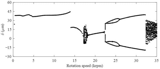
Figure 5.
The bifurcation behavior of the gear transmission without clearance.
Figure 6a illustrates the orbit, Poincaré and FFT plots at 17,040 rpm. A single closed curve in the orbit plot and a single point in Poincaré plot are observed, and the FFT plot shows a single synchronous frequency. These results indicate the gear system is a T-periodic motion at 17,040 rpm. However, a jump phenomenon appear in the gear system at 13,900 rpm. Then, the T-periodic motion transfers the chaotic motion, when the pinion speed increases to 17,214 rpm. Figure 6b illustrates the orbit, Poincaré and FFT plots at 17,214 rpm. Many curves and tangled points are observed in the orbit and Poincaré plots in Figure 6b, respectively. In addition, a continuous frequency spectrum appears in the FFT plot at 17,214 rpm. This result indicates that the gear system entered a chaotic motion. The chaotic motion continues until 18,435 rpm, then the chaos transforms to a T-periodic motion again.
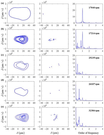
Figure 6.
The orbit, Poincaré and FFT plots at different speeds (a–e).
When the pinion speed increases to 22,445 rpm, the gear transmission system bifurcates to 4 T-periodic motion across a quasi-periodic motion in a short time. Four points are observed in the Poincaré plot at 25,235 rpm, and a quarter mesh frequency appears in the FFT plot, which indicates a 4 T-periodic motion, as shown in Figure 6c. The 4 T-periodic motion keeps up to 25,933 rpm, then transforms to a 2 T-periodic motion at 26,107 rpm. As shown in Figure 6d, two points are observed in the Poincaré plot at 26,107 rpm, and a half mesh frequency appears in the FFT plot, which indicates a 2 T-periodic motion. The gear system moves at 2 T-periodic motion until 32,210 rpm, and then transforms a chaotic motion again at 32,384 rpm, as shown in Figure 6e.
In the acceleration process, the bifurcation behavior of a gear transmission system with the clearance of 0.3 mm is illustrated in Figure 7. Comparing the bifurcation behavior of a gear transmission system without the clearance, the chaotic motion within the speed of 17,214–18,435 rpm disappears in the gear transmission system with the clearance of 0.3 mm. In gear drives, nonlinear dynamic behaviors are caused by the backlash and nonlinear mesh stiffness. When there is a clearance of 0.3 mm in the gear system, the change of backlash and mesh stiffness caused by revolute pair clearance induces the chaotic motion to disappear. As a result, the system with the clearance of 0.3 mm remains the T-period motion from 300 rpm to 23,849 rpm. Due to the existence of the clearance, the pinion speed at which the T-period motion transforms to the quasi-period motion is delayed from 22,445 rpm to 24,015 rpm. Then, the quasi-period motion directly transforms to a 2 T-period motion instead of the 4 T-period motion. However, the chaotic motion at the high-speed of the gear transmission system with a clearance of 0.3 mm is advanced to 29,594 rpm, and then bifurcates again into a 2 T-period motion at 32,384 rpm. The system remains the 2 T-period motion until it transforms to a T-period motion at 34,477 rpm.
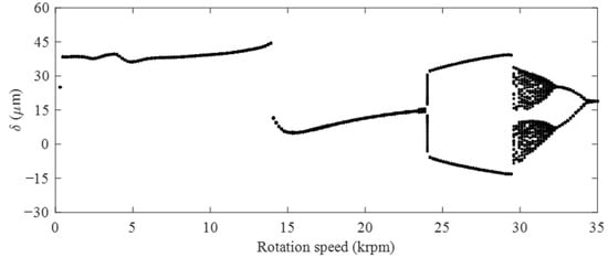
Figure 7.
The bifurcation behavior of the gear transmission with a clearance of 0.3 mm.
With the increase of the clearance from 0.3 mm to 0.6 mm, a chaotic motion is observed again in the medium-speed zone, but the corresponding speed range of the chaotic motion changed to 15,296–17,214 rpm, as shown in Figure 8. Compared with the case without clearance, the speed corresponding to quasi-periodic motion is still delayed, but it is advanced compared with the case with clearance of 0.3 mm. Compared with the case with 0.3 mm clearance, the speed corresponding to chaotic, 2 T-period and T-period in the high speed are advanced by a certain amount. These comparison results show the nonlinear behavior in the low speed of the gear system is insensitive to the clearance in revolute pair. But it will cause the appearance and disappearance of some nonlinear behaviors in the middle-speed and high-speed area, or change the speed corresponding to the nonlinear behavior of the gear transmission system.
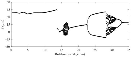
Figure 8.
The bifurcation behavior of the gear transmission with a clearance of 0.6 mm.
3.3. Vibration Response
RMS of the DTE of the gear pair with different clearances is predicted in acceleration process, as shown in Figure 9. With the increase in the clearance of the revolute pair, the RMS of the DTE becomes large, especially in the middle and high speed area. The RMS of the DTE drops suddenly in regions I and II, and the clearance in the revolute pair causes the sudden drop phenomenon in advance. This is because the clearance in revolute pair causes the speed corresponding to the nonlinear behavior to change.
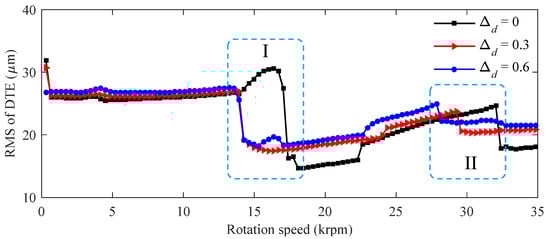
Figure 9.
RMS of the DTE of the gear pair in acceleration process.
To quantitatively study the influence of the clearance in revolute pairs on gear dynamics at different speeds, the DTE in time domain of the gear system with a clearance of 0.3 mm and 0.6 mm at low speed, medium speed and high speed are compared with the case without clearance, as shown in Figure 10. Where, the data of two mesh cycles are captured. With the increase of the clearance in the revolute pair, the amplitude of the DTE of the gear pair becomes large. The clearance has a slight effect on the DTE in the low-speed area (Figure 10a), but a considerable effect on the DTE in the medium-speed and high-speed area, as shown in Figure 10b,c.
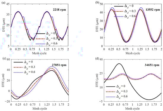
Figure 10.
The DTE of the gear pair at different speeds in time domain (a–d).
When the speed rises to 27,851 rpm, the DTE curve in Figure 10c illustrated one cycle. This result indicates that the clearance changes the nonlinear behavior and causes a 2 T-period motion for the gear system at the speed of 27,851 rpm. The gear system without clearance is in the chaotic motion at 34,651 rpm, while the system with clearance is in the T-period motion. If the clearance in the revolute pair causes the change of gear nonlinear behaviors, the amplitude of the DTE will not be positively correlated with the increase of the clearance, as shown in Figure 10d.
4. Conclusions
In this work, we presented a TVMS model of the gear drives with different clearances in the revolute pair. Then, a nonlinear dynamic model including the comprehensive influence of the contact ration, TVMS and backlash was proposed. According to the proposed dynamic model, the influence of the clearance in the revolute on TVMS, nonlinear behavior and vibration response were investigated, and the following conclusions are drawn.
(1) The clearance in the revolute pair will reduce the contact ration and weaken the TVMS of the spur gear pair. In further, the clearance will increase the working hours in single teeth contact area, thereby increasing the risk of premature failure of the gear drive.
(2) The gear nonlinear behavior in the low-speed area is insensitive to the clearance in revolute pair. However, it will cause the appearance and disappearance of some nonlinear behaviors in the middle-speed and high-speed area. The clearance can change the rotation speed corresponding to the nonlinear behavior, but the changed amplitude is not positively correlated with the clearance.
(3) The clearance in the revolute pair will aggravate the vibration the spur gear drive, especially in the medium-speed and high-speed area. In addition, the clearance will change the phase of gear vibration in the high-speed area. The change of backlash and mesh stiffness caused by the revolute pair clearance is the major reason enhanced gear vibration and sound.
The proposed model can be used to predict the dynamic behaviors of the gear drives with revolute pair clearance. Although it’s very difficult to test nonlinear behavior of gear drives at such high speeds, we hope that scholars with good experimental conditions can participate in the validation of the proposed dynamic model.
Author Contributions
Conceptualization, J.H., B.H., S.S. and H.W.; Methodology, J.H. and B.H.; Software, J.H., B.H. and H.W.; Validation, B.H. and S.S.; Formal analysis, J.H. and B.H.; Investigation, B.H. and M.X.; Resources, J.H., B.H. and S.S.; Data curation, J.H., B.H., C.P. and H.W.; Writing—original draft, J.H. and C.P.; Writing—review & editing, B.H. and S.S.; Visualization, B.H. and M.X.; Project administration, J.H., B.H. and S.S.; Funding acquisition, J.H. and S.S. All authors have read and agreed to the published version of the manuscript.
Funding
This research was funded by the National Natural Science Foundation of China (Grant No. 52005051 and 52175003), the Key Research and Development Program of Hunan Province (Grant No. 2018NK2061), the Key Research and Development Program of Guangdong Province (Grant No. 2020B0202010007), Natural Science Foundation of Hunan Province (Grant No. 2021JJ40580, 2021JJ30726 and 2021JJ40259). Excellent Youth Program of Hunan Education Department (Grant No. 20B307 and 20B017).
Data Availability Statement
No new data were created or analyzed in this study. Data sharing is not applicable to this article.
Conflicts of Interest
The authors declare no conflict of interest.
References
- Tuplin, W.A. Gear tooth stresses at high speed. Proc. Inst. Mech. Eng. 1950, 16, 162–167. [Google Scholar] [CrossRef]
- Mitchell, L.D.; David, J.W. Proposed Solution Methodology for the Dynamically Coupled Nonlinear Geared Rotor Mechanics Equations. J. Vib. Acoust. Stress Reliab. Des. 1985, 107, 112–116. [Google Scholar] [CrossRef]
- Özgüven, H.N.; Houser, D.R. Dynamic analysis of high speed gears by using loaded static transmission error. J. Sound Vib. 1988, 125, 71–83. [Google Scholar] [CrossRef]
- Kahraman, A.; Singh, R. Non-linear dynamics of a spur gear pair. J. Sound Vib. 1990, 142, 49–75. [Google Scholar] [CrossRef]
- Munro, R.G. The Dynamic Behaviour of Spur Gears; Cambridge University: Cambridge, UK, 1962. [Google Scholar]
- Wang, J.; Li, R.; Peng, X. Survey of nonlinear vibration of gear transmission systems. Appl. Mech. Rev. 2003, 56, 222–227. [Google Scholar] [CrossRef]
- Vaishya, M.; Singh, R. Sliding friction-induced non-linearity and parametric effects in gear dynamics. J. Sound Vib. 2001, 248, 671–694. [Google Scholar] [CrossRef]
- Vaishya, M.; Singh, R. Analysis of periodically varying gear mesh systems with coulomb friction using floquet theory. J. Sound Vib. 2001, 243, 525–545. [Google Scholar] [CrossRef]
- Tamminana, V.K.; Kahraman, A.; Vijayakar, S. A Study of the Relationship Between the Dynamic Factor and the Dynamic Transmission Error of Spur Gear Pairs. In Proceedings of the ASME 2005 International Design Engineering Technical Conferences & Computers and Information in Engineering Conference, Long Beach, CA, USA, 24–28 September 2005; pp. 75–84. [Google Scholar]
- Xiao, Z.; Zhou, C.; Chen, S.; Li, Z. Effects of oil film stiffness and damping on spur gear dynamics. Nonlinear Dyn. 2019, 96, 145–159. [Google Scholar] [CrossRef]
- Mitchell, L.D.; Mellen, D.M. Torsional-Lateral Coupling in a Geared, High Speed Rotor System. J. Mech. Eng. 1975, 97, 95. [Google Scholar]
- Walha, L.; Fakhfakh, T.; Haddar, M. Nonlinear dynamics of a two-stage gear system with mesh stiffness fluctuation, bearing flexibility and backlash. Mech. Mach. Theory 2009, 44, 1058–1069. [Google Scholar] [CrossRef]
- Gou, X.; Zhu, L.; Qi, C. Nonlinear dynamic model of a gear-rotor-bearing system considering the flash temperature. J. Sound Vib. 2017, 410, 187–208. [Google Scholar] [CrossRef]
- Liu, X.; Liu, D.; Hu, X. Influence of the Bearing Thermal Deformation on Nonlinear Dynamic Characteristics of an Electric Drive Helical Gear System. Sensors 2021, 21, 309. [Google Scholar] [CrossRef]
- Fu, D.; Gao, S.; Liu, H. Study on Dynamics of a Two-Stage Gear Transmission System with and without Tooth Breakage. Processes 2021, 9, 2141. [Google Scholar] [CrossRef]
- Cao, Z.; Shao, Y.; Rao, M.; Yu, W. Effects of the gear eccentricities on the dynamic performance of a planetary gear set. Nonlinear Dyn. 2018, 91, 1–15. [Google Scholar] [CrossRef]
- Wang, G.; Chen, L.; Yu, L.; Zou, S. Research on the dynamic transmission error of a spur gear pair with eccentricities by finite element method. Mech. Mach. Theory 2017, 109, 1–13. [Google Scholar] [CrossRef]
- Chen, S.; Tang, J.; Wu, L. Dynamics analysis of a crowned gear transmission system with impact damping: Based on experimental transmission error. Mech. Mach. Theory 2014, 74, 354–369. [Google Scholar] [CrossRef]
- Pan, W.; Li, X.; Wang, L.; Yang, Z. Nonlinear response analysis of gear-shaft-bearing system considering tooth contact temperature and random excitations. Appl. Math. Model. 2019, 68, 113–136. [Google Scholar] [CrossRef]
- Doğan, O.; Karpat, F. Crack detection for spur gears with asymmetric teeth based on the dynamic transmission error. Mech. Mach. Theory 2019, 133, 417–431. [Google Scholar] [CrossRef]
- Li, Z.; Peng, Z. Nonlinear dynamic response of a multi-degree of freedom gear system dynamic model coupled with tooth surface characters: A case study on coal cutters. Nonlinear Dyn. 2016, 84, 271–286. [Google Scholar] [CrossRef]
- Xun, C.; Long, X.; Hua, H. Effects of random tooth profile errors on the dynamic behaviors of planetary gears. J. Sound Vib. 2018, 415, 91–110. [Google Scholar] [CrossRef]
- Zhang, C.; Wei, J.; Peng, B.; Cao, M.; Hou, S.; Lim, T.C. Investigation of dynamic similarity of gear transmission system considering machining error distortion: Theoretical analysis and experiments. Mech. Mach. Theory 2022, 172, 104803. [Google Scholar] [CrossRef]
- Chen, S.; Tang, J. Effects of staggering and pitch error on the dynamic response of a double-helical gear set. J. Vib. Control. 2015, 46, 55–57. [Google Scholar]
- Tian, G.; Gao, Z.H.; Liu, P.; Bian, Y.S. Dynamic Modeling and Stability Analysis for a Spur Gear System Considering Gear Backlash and Bearing Clearance. Machines 2022, 10, 439. [Google Scholar] [CrossRef]
- Chaari, F.; Fakhfakh, T.; Haddar, M. Analytical modelling of spur gear tooth crack and influence on gearmesh stiffness. Eur. J. Mech. A Solids 2009, 28, 461–468. [Google Scholar] [CrossRef]
- Chen, Z.; Shao, Y. Mesh stiffness calculation of a spur gear pair with tooth profile modification and tooth root crack. Mech. Mach. Theory 2013, 62, 63–74. [Google Scholar] [CrossRef]
- Ma, H.; Pang, X.; Feng, R.; Zeng, J.; Wen, B. Improved time-varying mesh stiffness model of cracked spur gears. Eng. Fail. Anal. 2015, 55, 271–287. [Google Scholar] [CrossRef]
- Chen, K.; Huangfu, Y.; Ma, H.; Xu, Z.; Li, X.; Wen, B. Calculation of mesh stiffness of spur gears considering complex foundation types and crack propagation paths. Mech. Syst. Signal Process. 2019, 130, 273–292. [Google Scholar] [CrossRef]
- Shao, Y.; Chen, Z. Dynamic features of planetary gear set with tooth plastic inclination deformation due to tooth root crack. Nonlinear Dyn. 2013, 74, 1253–1266. [Google Scholar] [CrossRef]
- Jiang, H.; Shao, Y.; Mechefske, C.K. Dynamic characteristics of helical gears under sliding friction with spalling defect. Eng. Fail. Anal. 2014, 39, 92–107. [Google Scholar] [CrossRef]
- Liu, X.; Yang, Y.; Zhang, J. Investigation on coupling effects between surface wear and dynamics in a spur gear system. Tribol. Int. 2016, 101, 383–394. [Google Scholar] [CrossRef]
- Li, S.; Anisetti, A. The Effect of Spur Gear Tribo-Dynamic Response on Pitting Crack Nucleation. In Proceedings of the ASME International Power Transmission and Gearing Conference, Cleveland, OH, USA, 6–9 August 2017; p. V010T011A001. [Google Scholar]
- Ma, H.; Song, R.; Pang, X.; Wen, B. Time-varying mesh stiffness calculation of cracked spur gears. Eng. Fail. Anal. 2014, 44, 179–194. [Google Scholar] [CrossRef]
- Sainsot, P.; Velex, P.; Duverger, O. Contribution of Gear Body to Tooth Deflections—A New Bidimensional Analytical Formula. J. Mech. Des. 2004, 126, 748–752. [Google Scholar] [CrossRef]
- Ma, H.; Zeng, J.; Feng, R.; Pang, X.; Wen, B. An improved analytical method for mesh stiffness calculation of spur gears with tip relief. Mech. Mach. Theory 2016, 98, 64–80. [Google Scholar] [CrossRef]
- Zhou, C.; Hu, B.; Qian, X.; Han, X. A novel prediction method for gear friction coefficients based on a computational inverse technique. Tribol. Int. 2018, 127, 200–208. [Google Scholar] [CrossRef]
- Hu, Z.; Tang, J.; Zhong, J.; Chen, S.; Yan, H. Effects of tooth profile modification on dynamic responses of a high speed gear-rotor-bearing system. Mech. Syst. Signal Process. 2016, 76–77, 294–318. [Google Scholar] [CrossRef]
- Hu, B.; Zhou, C.; Wang, H.; Chen, S. Nonlinear tribo-dynamic model and experimental verification of a spur gear drive under loss-of-lubrication condition. Mech. Syst. Signal Process. 2021, 153, 107509. [Google Scholar] [CrossRef]
Disclaimer/Publisher’s Note: The statements, opinions and data contained in all publications are solely those of the individual author(s) and contributor(s) and not of MDPI and/or the editor(s). MDPI and/or the editor(s) disclaim responsibility for any injury to people or property resulting from any ideas, methods, instructions or products referred to in the content. |
© 2023 by the authors. Licensee MDPI, Basel, Switzerland. This article is an open access article distributed under the terms and conditions of the Creative Commons Attribution (CC BY) license (https://creativecommons.org/licenses/by/4.0/).