Abstract
Producing highly efficient electric motors remains a challenge nowadays. Given that the legislation in the field requires the transition to the production of engines with increased efficiency, for manufacturing companies, switching from one generation of engines to another can be a difficult task. This paper analyzes ways to adapt the assembly of engines of the IE4 generation starting from the assembly lines of the engines of the previous generation, IE3. The analysis of the assembly process covers both the operator training part and the actual assembly part. Ten possible variants for the assembly line and specific decisional variables have been defined. The decision to choose the optimal assembly configuration was made using as management tools the matrix of consequences and utilities. The validation of the theoretical model of the assembly line was carried out through a case study built for two classes of electric motors, namely G90 and G180. For a total production of IE4 electric motors of 20,000 parts/month, the analyzed variants, respectively, the two sizes (G90 and G100) represent 35% (7000 parts/month) of the G90 size and 22% (4400 parts/month) the G100 size. The aim is to provide a new modular assembly concept, which depending on the orders, can use, as given in the conclusion of this article.
1. Introduction
Asynchronous electric motors play a major role in the current human civilization. The transformation of electrical energy into the rotary motion of a shaft is the basis of the operation of a multitude of machines and equipment [1,2,3]. As the main actuation element, the efficiency of converting electrical energy into mechanical energy is an ongoing concern. In this sense, efficiency standards have been developed [2,4]. The International Electrotechnical Commission (IEC) developed 5 efficiency standards, IE1÷IE5, but for now, the industry assimilates the IE4 standard [1,2,4].
In the activity of designing new types of engines, the following aspects are taken into account:
- reduction of losses (in the stator winding, in the stator core, but also for slip losses in the rotor);
- according to [5,6], solutions will be sought such as the copper windings will have a higher profile (deeper notches in the stator or rotor core), thinner (below 0.5 mm), and steel sheets will be used better for the core (Fe + C + Si alloy sheets obtained by more special laminations);
- at the same time, the gap will be reduced, and the induced reaction (inherently increased by reducing the distance between the stator and the rotor) will be improved by specific methods (providing damping bars for rotors with visible poles or designing pole pieces for those with buried poles, or through other more innovative methods) [7];
- special attention will be paid to self-ventilation through redesign and simulation with specialized software [8];
- better-performing bearings will be used for the motor shaft, both to increase mechanical efficiency in order to improve reliability and constructive solutions for easy maintenance [9,10,11,12].
If the IE1÷IE5 asynchronous electric motors are compared with each other, it is found that in most cases, they contain almost the same features, the differences being the motor mounting, the motor size, etc. [13]. From the point of view of efficiency, the standards regulate the following classification [1]:
- IE1 (standard efficiency);
- IE2 (high efficiency);
- IE3 (premium efficiency);
- IE4 (super premium efficiency);
- IE5 (ultra-premium efficiency—still little documentation).
Accepting the finding made previously, it follows that the design of the assembly technological flow could be based on the existing one. Depending on the demand, in most cases, the assembly of electric motors is done on an assembly line with a discrete (discontinuous) cycle [14,15,16].
The transition to the assembly of IE4 asynchronous motors on existing assembly lines (where IE3 asynchronous motors are assembled) involves the development of an assembly strategy [17].
This paper is structured as follows: The aforementioned challenges towards successfully manufacturing superior engines in terms of energy efficiency, starting from the manufacturing lines of engines with the lower efficiency class, motivated the proposed research.
In this research, a model of a modular assembly system is constructed. The modeling process and optimization process are balanced online. The proposed method greatly improves the optimization accuracy and efficiency of complex assembly processes compared to other existing methods. Moreover, because the proposed method is implemented online without interrupting the production line, it greatly decreases the manufacturing cost.
The proposed algorithms will advance the state-of-the-art technology to the course of optimal manufacturing process performance.
2. Materials and Methods
The case study results from a 2-year collaboration with Company Beta. In the three-phase asynchronous electric motor market, there is an increase in demand for motors with sizes G90 and G100. This finding makes it opportune to move the two sizes from the IE3 standard to the IE4 standard. After design and approval, the two sizes in the IE4 standard will be assimilated into the series production of existing assembly lines. In order to harmonize with the assembly of motors in the IE3 standard, it is necessary to develop a strategy from the design phase of the assembly [18].
2.1. Design Strategy for the Assembly Technological Flow
In order to create a complete assembly documentation that is simple, easy to understand and to apply, regardless of the standard of the motors, the following steps can be taken:
- (a)
- Grouping of engines by size (in most cases, it is done);
- (b)
- Analysis of the drawings by dimensions and numbering, with the same digit, of the common parts (as a rule, this aspect is neglected);
- (c)
- Identifying the parts that are used for several dimensions (it is necessary to establish the production capacity or to purchase them);
- (d)
- Elaboration of the detailed assembly operation plan at the operation level (the part number from the engine drawing will be indicated), phases, handling and movements; explanations will be given with photos (necessary for training);
- (e)
- During the control operation, all activities will be highlighted in logical and temporal order with the quantitative indication of the parameters to be measured (as a rule, it is not given the needed importance);
- (f)
- Identifying assembly operations where mistakes can be made (e.g., the order of colored wires in the terminal box is practiced) and establishing preventive measures.
- (g)
- Identifying solutions to prevent the incorrect order of the wires (e.g., a dot of colored paint next to the terminal), an operation that will be included in the operations plan.
2.2. Analysis of the Possibility of Assembling IE4 Electric Motors on IE3 Three-Phase Asynchronous Motor Assembly Lines
To see if it is possible to mount the IE4 engines on the assembly lines of the IE3 engines, it is necessary to go through the following steps [19,20,21]:
- Establishing the number of electric motors and their power (the size of the electric motor depends on the desired power) to be carried out monthly. For this purpose, the number of IE3 electric motors assembled at least three months ago (if data is given, preferably 6 months) is analyzed, identifying the trend of increasing or decreasing demand. At the same time, the sizes with the most orders will be identified;
- Assimilation of assembly operations and operating times from IE3 electric motors to IE4 electric motors;
- Based on the operational times, the current production capacity will be determined (a single shift will be considered) for each operation, and it will be compared with the number of IE4 electric motors proposed to be assembled each month;
- If it is found that it is not enough to work in one shift, an analysis of the production capacity will be made for two and three shifts;
- In order to establish the strategy of development, the predominant manufacturing series will be determined.
2.3. Case Study on the Possibility of Assembling IE4 Three-Phase Asynchronous Electric Motors on IE3 Motor Assembly Lines
Enterprise Beta has to assimilate in manufacturing the three-phase asynchronous electric motors in the IE4 efficiency standard. After design and homologation, based on the first step in Section 2.2, it was decided to produce monthly 20,000 three-phase asynchronous electric motors IE4 of various sizes. The technological process of assembling IE3 engines was extrapolated for IE4 engines.
Further, based on the first step from Section 2.2 a division by dimensions was carried out similar to the data in Figure 1, where it can be seen, for 3 months, the assembled number of electric motors from the IE3 standard.
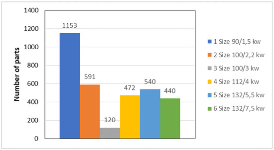
Figure 1.
Assembled motors in 3 months.
From Figure 1, it can be seen that 3316 engines were produced, with an average of 1105 engines per month. The largest share is held by the electric motor G90/1.5 kw (≈35%), followed by the electric motors G100/2.2 kw and 3 kw (≈22%), which explains the start of the design of new engines in the IE4 standard with these two models. At the same time, it can be noted the diversity of the orders and the fact that the engines of larger size, even if individually they were produced in a smaller series, three sizes, added up, slightly exceeding the production of engines in the IE3 standard, size 90.
Diversity is the main characteristic that objectively determines ways to achieve a flexible assembly.
The current assembly, on long linear lines, must be analyzed from the flexibility point of view, which implies the identification of solutions for making it more flexible.
For the case study, the two sizes (G90 and G100) that will be produced will be analyzed. Out of the total of 20,000 IE4 motors/month, 35% G90 size and 22% G100 size, i.e., 7000 motors/month G90 and 4400 motors/month G100.
In Table 1, without detailing the phases and very close to reality, the operative production times are given for each assembly operation (step 2 from Section 2.2). The assembly of the stator is also included in the technological assembly process. Accordingly, the term assembly-mounting will be used [20,21,22,23].

Table 1.
Operating times for each assembly-mounting operation.
To determine the production capacity for each assembly-mounting operation (step 3 from Section 2.2), it is necessary to calculate the annual effective time fund. Considering Zc as the number of calendaristic days, Z1—number of working days, Ks—shifts coefficient, and h—number of working hours per day, Table 2 shows the determination of the annual and monthly effective time fund for one shift.
Table 2.
Determination of the annual and monthly effective time fund for one shift.
The production capacity for each operation monthly is determined with the relation (1).
where:
- Cp—production capacity;
- Ks—shifts coefficient (Ks = 1; Ks = 2; Ks = 3);
- top [min]—operational production time.
Table 3 summarizes the production capacity, at each operation, of an assembly-mounting line when working in one, two or three shifts, compared to the monthly production plan.
Table 3.
The production capacity for each assembly-mounting operation.
The assembly-mounting process consists of the following operations: 010—stator assembly (on the specialized machine, outside the assembly line); 020—drilling–riveting; 030—assembling “terminal box”; 040—motor mounting; 050—control; 060—assembling; 070—engine completion (mounting label, etc.).
Based on the data in Table 3 allow, the following conclusions are drawn:
- Assembly of the IE4 G90 electric motor at Nmonthly = 7000 pieces can only be done if the assembly-mounting line works in 2 shifts;
- The assembly of the electric motor IE4 G100 at Nmonthly = 4400 pieces can only be done if the assembly-mounting line works in 2 shifts, but by adopting the organizational measures for operation 030;
- If desired to assemble 20,000 pieces/month of the G90 size, one more assembly-mounting line is needed, and both lines must work in 3 shifts;
- To synchronize assembly-mounting operations, especially since the assembly conveyor is used, the operator from operation 020 will be trained to carry out operation 030 as well;
- Organizational measures will be adopted so that an operator can perform operations 050, 060 and 070;
- The transition to two and three shifts requires the hiring of new operators, which implies their training.
3. Results
In order to be able to identify the organizational measures needed to assemble the IE4 electric motors on the assembly lines of IE3 motors, it is necessary to determine the length of the assembling lines with the identification of the active area [24,25,26]. At the same time, in order to establish the assembly-mounting strategy, it is useful to determine the manufacturing series [27].
3.1. Analysis of Assembly-Mounting Lines of IE3 Three-Phase Asynchronous Motors
Enterprise Beta performs the assembly operations of the IE3 asynchronous electric motors on two assembly lines (Figure 2). The dimensions in the figure are not real ones but are very close to reality.
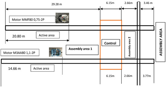
Figure 2.
Determining the length of the assembly conveyors on which the IE4 asynchronous motors will be mounted.
The lengths of the active zones for two types of IE3 engines of G80 size were identified. A passive area is found between operations 040 and 050, where electricity is consumed unnecessarily.
Obviously, the dimensions of the assembly conveyors have been established for assembling the IE3 electric motor of the largest size, size which also has the longest length, in which case the length of the passive area of the conveyor is minimal. The above observation highlights the rigidity of the assembly lines in the case of medium series production [28,29,30].
3.2. Identifying the Way to Train the New Employed Operators
The transition to the assembly-mounting of electric motors in 2 or 3 shifts, as mentioned in Section 3, requires the training of the newly hired operators. Currently, the training is carried out directly on the assembly line through the observation method (Figure 3a) and then the operator is put to work on the assembly line (Figure 3b).
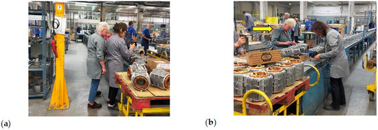
Figure 3.
(a) Training through the method of observation; (b) The new operator working on the assembly conveyor.
The method used has advantages and disadvantages.
Advantages: the observation is made directly on the assembly line; the operator contributes directly to the assembly; minimal cost for training.
Disadvantages: the operator can lead to wrong assembles; assembly time slows down due to lack of dexterity; the risk of injury also increases due to the lack of dexterity.
In conclusion, the productivity of the assembly line will decrease due to the previously stated reasons.
3.3. The Possibility of Optimization of the Assemblymounting in the Variant of Using Assembly Conveyors
If the demand changes, the cadence of the assembly line changes as well. If line flexibility is low during peak periods, the assembly line may not be able to fulfill the demand, and if the demand drops, the assembly line will operate below capacity.
According to [23,31,32,33], typically, the average production potential of an assembly system is given by the assembly time of a product (t/pc) multiplied by the number of products to be assembled in a period of time. As this potential usually exceeds the possibilities of a workplace, it is necessary to split it. The split can be made both vertically and horizontally.
When mounting the IE4 three-phase asynchronous electric motors, all three variants can be considered, given the surplus surface intended for assembly.
Regardless of the adopted system, compared to the initial situation, it is necessary to change the number of operators but also to supplement the technical means, especially if the work plan is 3 shifts of 8 h each.
When assembling electric motors, splitting the assembly is preferred when the production plan is various and the electric motors are easy to handle.
If the electric motors are large sized, their maneuverability is difficult, and as a result, an operator performs several assembly operations at the same workplace (concentration of assembly operations); therefore, the assembly is not cost-effective to be carried out on assembly conveyors.
When it is necessary to increase the assembled number of electric motors in the same time interval, adaptation options can be developed. Figure 4 shows an example of adaptation to the initial situation The variant (Figure 4a) of the assembly line a can be split vertically. Two new variants of configurations are described in Figure 4b,c.
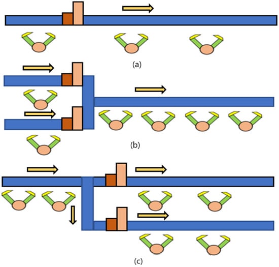
Figure 4.
Variants of adapting the assembly compared to the initial situation (a) to the increase of the assembly cadence (b,c).
Due to the fluctuating market of electric motors, there may be a situation when the cadence of assembly decreases, and as a consequence, compared to the initial situation, (Figure 5a) adaptation options can be developed (Figure 5b,c).
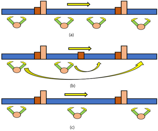
Figure 5.
Variants to adapt the assembly compared to the initial situation (a) to the decrease in the assembly cadence (b,c).
The previous solutions regarding the increase (Figure 4) or decrease (Figure 5) of the assembly cadence do not remove the lack of flexibility of the assembly. In order to adopt an effective solution, it is necessary to determine the production system and, depending on it, to develop radical optimization solutions. The specialized literature [23] presents two methods with the widest use in determining the production system (type), namely, the method of global indices and the method of constancy indices.
For the assembly-mounting of electric motors, it is recommended to use the method of constancy indices that establishes the production system (type) at the part-operation level in order to identify the degree of homogeneity and stability over time of the operations at each workplace.
3.4. A New Way of Assembly-Mounting and Training—Case Study
Variants of Training Cells
As highlighted in the previous chapters, it is possible to assemble the new IE4 electric motors on the current assembly lines. At the same time, it was pointed out that the demand is diverse, which leads to the improper use of assembly conveyors. The transition to the electric motors assembling in 2 and 3 shifts requires the training of new employees. The training on assembling conveyors by the observation method has substantial disadvantages with consequences for production.
A solution that is practiced in other enterprises in the electrotechnical industry, but not only, is the creation of training cells where the operators will be trained to assemble, by themselves, the entire electric motor. From the training cell, they will be promoted to work on the assembly conveyors.
Because the assembly conveyor is characterized by productivity but also by rigidity when changing the type of electric motor, for the Company Beta, it is proposed to create modular training cells, which can easily be configured as an assembly conveyor.
Starting from the assembly-mounting operations presented in Table 1, it is proposed to create training cells composed of 4 training modules. At a training module, all assembly-mounting operations will be performed, except operation 010, which requires a specialized machine.
The operator training cells required for the assembly of IE4 three-phase motors will be designed with a dual role, namely, that of training but also that of assembly of electric motors of large size or that are produced in small series. At the same time, they can also be used for future electric motors in the IE5 standard, mounting both 1 piece for assimilations and the zero series for approvals.
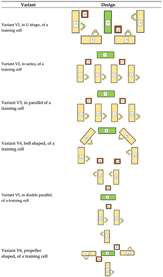
Figure 6.
V1–V6 training configuration, where: 1, 2, 3, 4—Work modules; 5—Control module; 6—Mobile transport modules to the control module.
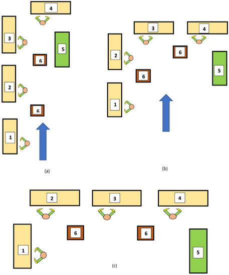
Figure 7.
Right angle configuration (a–c). Variant 2, in series, of a training cell (a); Right angle configuration, V8 variant (b); Right angle configuration, V9 variant (c). The modules are: 1, 2, 3, 4—Work modules; 5—Control module; 6—Mobile transport modules to the control module.
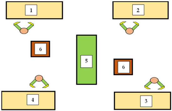
Figure 8.
Back-to-back configuration, V10 variant, where: 1, 2, 3, 4—Work modules; 5—Control module; 6—Mobile transport modules to the control module.
The determination of the training station number in a cell (4 stations) was based on the current assembly technological process, presented in Table 1, as well as on the possibility of transforming a training cell into an assembly cell or even an assembly line. Module 5, the control, is not considered a permanent training position. In this module, after finishing the assembly, each operator comes for verification. On this occasion, he is trained in the control operation.
The configuration in Figure 7, in right angle, has 3 subvariants, depending on the way the training modules and the control module are placed.
If desired to transform a training cell into an assembly cell, it is found, based on Figure 8, that operation 020 and operation 030 can be performed on a single assembly module, and after the Control operation, the engine will be transported to the packaging and storage, in this way resulting in the need for 5 specialized tables. Assembly operation 010, requiring specialized equipment, and being at the beginning, will be carried out separately from the training-assembly cell.
When designing any equipment and machinery used by workers, it is necessary to respect the principles of ergonomics. The main element of the training cell is the work module. If the assembly tables will be designed in a modular mobile system and if it is desired that a training cell be transformed into an assembly cell for small and unique series, the training cell must be completed with mobile storage for parts.
For the training cell, a working module will be created that must meet the following requirements:
- The work surface must be consistent with the largest size of the electric motor to be assembled;
- The electric motor will be placed on a table on which there is a rubber surface;
- The tabletop, on which the electric motor is placed, will be made mobile so that it can be easily rotated but also moved on rollers on the work table;
- The work on the module will be done in an orthostatic position (standing) so that the operator will get used to and integrate easily into assembly on the conveyor belt;
- The work table will be placed on a mobile platform, resulting in a working module and thus, the desired configuration can be achieved;
- The total height of the work module (including the mobile platform) will comply with ergonomic principles;
- The coupling of the modules must be quick, easy and safe.
3.5. Choosing the Optimal Variant for the Training Cell for the Assembly of IE4 Electric Motors
3.5.1. Theoretical Aspects Regarding Decisions under Conditions of Certainty—Global Utility Method
To choose the optimal variant for the training cell, the global utility method will be applied. After stating the decision problem, the matrix of consequences is created.
The characterization of the decision-making process is carried out considering:
- the set of variants (Vi), where i ϵ {1, 2, … m};
- the set of criteria for evaluating the variants (Cj), where j ϵ {1, 2, … n};
- importance coefficients for criteria (kj), where k ϵ {1, … n};
- matrix of consequences C = (cij)—consequences where, i ϵ {1, 2, … m}, j ϵ {1, 2, … n}.
After creating the matrix of consequences, the matrix of utilities will be created. Utilities have values between 0 and 1. They are calculated according to the relation:
where:
- c1j—the most favorable consequence;
- c0j—the most unfavorable consequence;
- cij—current consequence.
The decision based on the utility matrix will generate as the optimal variant the one for which the relation (2) is fulfilled.
If the consequences k(1) = k(2) = …. k(j) ……… = k(n), then the optimal variant Vopt will be the one that fulfills the relation (3).
3.5.2. Choosing the Optimal Variant by the Global Utility Method—Case Study
In order to create the matrix of consequences and the matrix of utilities, it is necessary to establish the assessment criteria and the importance of each criterion for all variants of training cells [23,26]. In the case of training cells, in order to assemble IE4 engines, the evaluation criteria can be the following:
- C1—Training cell surface;
- C2—Maximum distance to control table;
- C3—The shape of the surface occupied by the training cell (ratio L/l);
- C4—The degree of universality of the cell (it can turn easy, medium or difficult into an assembly cell).
The importance coefficient of each criterion can be:
- Training cell surface, k1 = 0.25;
- Maximum distance to control table, k2 = 0.15;
- The shape of the surface occupied by the training cell (ratio L/l), k3 = 0.2;
- The degree of universality of the cell (it can turn easy, medium or difficult into an assembly cell), k4 = 0.4.
In order to determine the surface occupied by each variant, it is necessary to measure the component elements taking into account the ergonomic principles.
- Training module surface SM = 1.2 mp;
- Surface of the control and labeling module SCL = 1.2 mp;
- Transport module surface STR = 0.64 mp;
- Distance between training modules DM = 1000 mm;
- Distance between training module, control module and access path or walls DAP = 1000 mm.
The above data are simulated data; they will change according to the maximum size of the new generation of engines and respecting the ergonomic elements.
The matrix of consequences for the 10 variants of training cells can be seen in Table 4.
Table 4.
Matrix of consequences.
With the help of the matrix of consequences, the matrix of utilities is created (Table 5).
Table 5.
Utility and decision matrix for training cells and, if necessary, conversion to serial assembly cell.
On column 1 utility 1, the most favorable consequence is c41 = 20 sq m, and this will receive utility u(4, 1) = 1. The most unfavorable consequence in column 1 is c31 = 30.8 sq m, and this will receive utility u(3, 1) = 0. The difference between the two consequences is c41 − c31 = 10.8 sq m. The other utilities in the first column will be determined with the relation presented previously.
Table 5 shows that the optimal variant of the training cell and if desired, its transformation into a serial assembly cell (modules are connected in the order of assembly operations) is V2.
However, if the cell is only for training, criterion 4 will be dropped, and the decision will be made according to Table 6.
Table 6.
Utility and decision matrix for training cells only.
Table 6 shows that the optimal cell variant only for training is V6.
If it is desired to assemble several electric motors in parallel (e.g., a series of 5 pieces) where the operator will do the complete assembling, then the matrix of consequences will undergo changes to the fourth assessment criterion (Table 7), and the matrix of utilities and decision is shown in Table 8.
Table 7.
The matrix of consequences when the training cell is configurable for the complete assembly of the electric motor by an operator.
Table 8.
Utility and decision matrix when the training cell can be configured for complete assembly of the electric motor by an operator.
Another way of carrying out the assembly is proposed, namely the mixed one, where all the motor frames of the future electric motors are placed on a long bench, and the operator, after completing the entire assembly of an electric motor, will move to the next motor frame where will assemble completely another electric motor.
4. Discussion
In order to improve the assembly activity for assimilating the new IE4 three-phase motors, it is proposed to establish cells for the training of new operators and also for the training of experienced operators when a new product is assimilated. The novelty of the proposals consists of the following:
- A training module must allow the translation and rotation movement of the electric motor in various assembly phases to continue the assembly to another module when it is carried out in series (assembly conveyor);
- It is proposed to create mobile transport modules;
- If the training cell is also intended for assembly if needed, it is necessary to create modular storage for parts that can be easily supplied and, at the same time, easily moved;
- Observance of ergonomic elements is indispensable for minimizing operator fatigue during both training and assembly;
- A training module will have three levels: the first level is at the base of the module for mobility; the second level is the body of the module; the third level is the assembling table to allow the movements necessary to move and rotate the electric motor;
- 10 variants of training cells are developed and analyzed;
- To identify the optimal option according to the assessment criteria, the global utility method is used for decision-making, which reduces subjectivity to a minimum;
- Depending on the desired assessment criteria, it is found that the optimal option for the implementation of the training cell may be different;
- If the training cell is intended only for the training of new operators, then the V6 configuration is the optimal one;
- If the cell will be used both for training and, if necessary, for series or parallel assembly, the optimal variant is V2, which allows very easy configuration for the transition from training to series or parallel assembly;
- The matrix of consequences and utilities allows the decision to be made even when restrictions appear (e.g., the available space has the necessary area but is square-shaped), and in that situation the optimal option might be different.
The research implications of the assembly line proposal are highlighted by the applicability of such a model. Our focus was only on certain IE4 electrical motors production. Other approaches that are not included in this study may be integrated into the proposed method.
5. Conclusions
The developed research can lead to a new concept of assembly of electric motors at a specific enterprise, namely, the modular assembly concept, which depending on the orders, can use the optimal assembly configuration.
The training cells should be made modular so that the desired configuration can easily be mad and can be easily transformed into a serial assembly cell (assembly line). The assembly cell can be easily transformed into an assembly cell in the unique production (the electric motor will be completely assembled by the same operator).
It is proposed to create mobile training modules that, if necessary, can be arranged into any configuration.
As a limitation of the present work, it is noted that the customization of the assembly problem, in particular, aims at the transition from the production of IE4 engines by adapting the existing manufacturing lines for the engines of the IE3 efficiency class. As a future direction of research, the authors aim to generalize this solution.
Author Contributions
Conceptualization, A.L.P., R.D. and G.O.; methodology, A.L.P. and G.O.; software, R.D. and M.V.D.; validation, A.L.P., R.D. and M.R.; formal analysis, G.O.; investigation, M.V.D. and G.O.; resources, A.L.P. and M.R.; writing—original draft preparation, M.V.D.; writing—review and editing, G.O.; supervision, G.O.; project administration, A.L.P.; funding acquisition, M.R. All authors have read and agreed to the published version of the manuscript.
Funding
This research was funded by Ministerul Cercetării, Inovării și Digitalizării prin Programul Operational Competitivitate, Romania (Ministry of Research, Innovation, and Digitalization through the Operational Program Competitively, Romania) project “Cresterea competitivitatii Eletroprecizia Electrical Motors prin dezvoltarea in parteneriat cu Universitatea Transilvania a unei noi familii de motoare electrice, cu eficienta energetica de clasa superpremium (IE4) (Increasing the competitiveness of Electroprecizia Electrical Motors by developing in partnership with Transilvania University a new electrical motors family with super-premium energetically class (IE4))/121228/POC/163/1/3” (translation from Romanian).
Conflicts of Interest
The authors declare no conflict of interest.
References
- Commission Regulation (EU) 2021/341 of 23 February 2021 with Regard to Ecodesign Requirements for Servers and Data Storage Products, Electric Motors and Variable Speed Drives, Refrigerating Appliances, Light Sources and Separate Control Gears, Electronic Displays, Household Dishwashers, Household Washing Machines and Household Washer-Dryers and Refrigerating Appliances with a Direct Sales Function. Available online: https://eur-lex.europa.eu/legal-content/EN/TXT/PDF/?uri=CELEX:32021R0341&from=EN (accessed on 20 May 2022).
- Commission Regulation (EU) 2019/1781 of 1 October 2019 Laying down Ecodesign Requirements for Electric Motors and Variable Speed Drives Pursuant to Directive 2009/125/EC of the European Parliament and of the Council, Amending Regulation (EC) No 641/2009 with Regard to Ecodesign Requirements for Glandless Standalone Circulators and Glandless Circulators Integrated in Products and Repealing Commission Regulation (EC) No 640/2009. Available online: https://op.europa.eu/en/publication-detail/-/publication/218c6599-f734-11e9-8c1f-01aa75ed71a1 (accessed on 20 May 2022).
- Super-Efficient Equipment and Appliance. Deployment (SEAD) Initiative. Available online: https://www.cleanenergyministerial.org/content/uploads/2022/11/sead-briefing-live-nov22-1.pdf (accessed on 16 January 2022).
- IEC 60034-30-1:2014. Rotating Electrical Machines–Part 30-1: Efficiency Classes of Line Operated AC Motors (IE Code). Available online: https://webstore.iec.ch/publication/136 (accessed on 20 May 2022).
- Zhang, Q.; Zhao, J.; Yan, S.; Xiong, Y.; Ma, Y.; Chen, H. Virtual Voltage Vector-Based Model Predictive Current Control for Five-Phase Induction Motor. Processes 2022, 10, 1925. [Google Scholar] [CrossRef]
- Wang, F.; Zhang, Z.; Mei, X.; Rodríguez, J.; Kennel, R. Advanced Control Strategies of Induction Machine: Field Oriented Control, Direct Torque Control and Model Predictive Control. Energies 2018, 11, 120. [Google Scholar] [CrossRef]
- Kodkin, V.L.; Baldenkov, A.A. Experimental Studies of the Processes of Stepped Torque Loads Parrying by Asynchronous Electric Drives and Interpretation of Experimental Results by Nonlinear Transfer Functions of Drives. Processes 2022, 10, 1204. [Google Scholar] [CrossRef]
- Kodkin, V.; Anikin, A. Experimental Studies of Nonlinear Dynamics of Asynchronous Electric Drives with Variable Load. Processes 2022, 10, 1068. [Google Scholar] [CrossRef]
- Waide, P.; Brunner, C.U. Energy-Efficiency Policy Opportunities for Electric Motordriven Systems; Working paper; International Energy Agency; OECD Publishing: Paris, France, 2011. [Google Scholar]
- Fleiter, T.; Eichhammer, W. Energy Efficiency in Electric Motor Systems: Technology, Saving Potentials and Policy Options for Developing Countries; Working Paper; UNIDO United Nations Industrial Development Organization: Vienna, Austria, 2012. [Google Scholar]
- EIA. Energy Efficiency 2018—Market Report Series; U.S. Energy Information Administration (EIA): Washington, DC, USA, 2018; Available online: https://www.iea.org/reports/energy-efficiency-2018 (accessed on 20 April 2022).
- DOE. Premium Efficiency Motor Selection and Application Guide: A Handbook for Industry; Department of Energy: Washington, DC, USA, 2014. Available online: https://www.osti.gov/biblio/1220835 (accessed on 20 April 2022).
- Bortoni, E.C. Are my motors oversized? Energy Convers. Manag. 2009, 50, 2282. [Google Scholar] [CrossRef]
- Kalaiselvan, A.S.V.; Subramaniam, U.; Shanmugam, P.; Hanigovszki, N. A comprehensive review on energy efficiency enhancement initiatives in centrifugal pumping system. Appl. Energy 2016, 181, 495–513. [Google Scholar] [CrossRef]
- Gavrila, H.; Manescu, V.; Paltanea, G.; Scutaru, G.; Peter, I. New trends in energy efficiency electrical machines. Procedia Eng. 2017, 181, 74. [Google Scholar] [CrossRef]
- De Almeida, A.T.; Ferreira, F.J.T.E.; Fong, J. Standards for efficiency of electric motors. IEEE Ind. Appl. Mag. 2011, 17, 9. [Google Scholar] [CrossRef]
- Pedra, J. Estimation of typical squirrel-cage induction motor parameters for dynamic performance simulation. Proc. IEEE Gener. Transm. Distrib. 2006, 153, 137. [Google Scholar] [CrossRef]
- Haque, M.H. Determination of NEMA design induction motor parameter from manufacturer data. IEEE Trans. Energy Convers 2008, 23, 997. [Google Scholar] [CrossRef]
- Alger, P.L. The Nature of Polyphase Induction Machines; John Willey and Sons, Inc.: New York, NY, USA, 1951. [Google Scholar]
- Bortoni, E.; Nogueira, L.; Cardoso, R.; Haddad, J.; Souza, E.; Dias, M.; Yamachita, R. Assessment of the achieved savings from induction motors energy efficiency labeling in Brazil. Energy Convers. Manag. 2013, 75, 40. [Google Scholar] [CrossRef]
- Guimarães, J.M.C.; Bernardes, J.V.; Hermeto, A.E.; Bortoni, E.C. Parameter determination of asynchronous machines from manufacturer data sheet. IEEE Trans. Energy Convers. 2014, 29, 689. [Google Scholar] [CrossRef]
- Kostenko, M.; Piotrovsky, L. Electrical Machines—Part 2; Mir Pub: Moscow, Russia, 1977. [Google Scholar]
- Chang, K.-H. Chapter 16—Decisions in Engineering Design. In e-Design; Chang, K.-H., Ed.; Academic Press: Cambridge, MA, USA, 2015; pp. 847–905. [Google Scholar] [CrossRef]
- Li, Y.; Liu, M.; Lau, J.; Zhang, B. A novel method to determine the motor efficiency under variable speed operations and partial load conditions. Appl. Energy 2015, 144, 234. [Google Scholar] [CrossRef]
- Pedra, J.; Córcoles, F. Estimation of induction motor double-cage model parameters from manufacturer data. IEEE Trans. Energy Convers. 2004, 19, 317. [Google Scholar] [CrossRef]
- De Almeida, A.T.; Ferreira, F.J.T.E.; Duarte, A. Technical and economic considerations on super high-efficiency three-phase motors. IEEE Trans. Ind. Appl. 2014, 50, 1274. [Google Scholar] [CrossRef]
- De Almeida, A.T.; Ferreira, F.J.T.E.; Baoming, G. Beyond induction motors technology trends to move up efficiency. IEEE Trans. Ind. Appl. 2014, 50, 2103. [Google Scholar] [CrossRef]
- Giraud, R.; Plasse, C. Technology to support Circular Economy: Will standardization limits the outstanding benefits of new motor technology with or without drive and the use of raw material content of electric motors. In Proceedings of the 10th International Conference on Energy Efficiency in Motor Driven Systems (EEMODS’2017), Rome, Italy, 6–8 September 2017. [Google Scholar]
- Son, J.C.; Yi, K.P.; Lim, D.K. Multi-Variable Multi-Objective Optimization Algorithm for Optimal Design of PMa-SynRM for Electric Bicycle Traction Motor. Processes 2021, 9, 1901. [Google Scholar] [CrossRef]
- Wang, H.; Tian, H. A fast and faithful collocation method with efficient matrix assembly for a two-dimensional nonlocal diffusion model. Comput. Methods Appl. Mech. Eng. 2014, 273, 19. [Google Scholar] [CrossRef]
- Chen, H.; Cheng, H. Online performance optimization for complex robotic assembly processes. J. Manuf. Process. 2021, 72, 544–552. [Google Scholar] [CrossRef]
- Bramerdorfer, G.; Cavagnino, A.; Vaschetto, S. Cost-optimal machine designs fulfilling efficiency requirements: A comparison of IMs and PMSMs. In Proceedings of the IEEE International Electric Machines and Drives Conference (IEMDC), Miami, FL, USA, 21–24 May 2017. [Google Scholar] [CrossRef]
- Sala, R.; Pirola, F.; Pezzotta, G.; Cavalieri, S. Data-Driven Decision Making in Maintenance Service Delivery Process: A Case Study. Appl. Sci. 2022, 12, 7395. [Google Scholar] [CrossRef]
Disclaimer/Publisher’s Note: The statements, opinions and data contained in all publications are solely those of the individual author(s) and contributor(s) and not of MDPI and/or the editor(s). MDPI and/or the editor(s) disclaim responsibility for any injury to people or property resulting from any ideas, methods, instructions or products referred to in the content. |
© 2023 by the authors. Licensee MDPI, Basel, Switzerland. This article is an open access article distributed under the terms and conditions of the Creative Commons Attribution (CC BY) license (https://creativecommons.org/licenses/by/4.0/).