Abstract
Sn-Pd electrocatalysts with a constant atomic ratio of 60 at.% Sn-40 at.% Pd suitable for potential application in direct ethanol fuel cells were synthesized using a novel two-step electrodeposition method. First, Sn was electrodeposited in various forms of dendrites, from spear-like and needle-like to individual fern-like dendrites to a network of intertwined fern-like dendrites, by varying the cathodic potential and then performing electrodeposition of Pd at a constant current density in the second step. A morphological and elemental analysis of Sn and Sn-Pd electrocatalysts was performed using scanning electron microscopy (SEM), energy-dispersive X-ray spectroscopy (EDS) and X-ray photoelectron spectroscopy (XPS) techniques, while the size of Sn dendrites was analyzed using the particle size distribution (PSD) method. Cyclic voltammetry (CV) and chronoamperometry were applied in order to study the catalytic behavior of Sn-Pd electrocatalysts in the ethanol oxidation reaction (EOR), while CO stripping was used to estimate the antipoisoning capability of the electrocatalysts. The Sn surface morphology of the sub-layer was highly correlated with the electrocatalytic activity of the examined Sn-Pd electrocatalysts. The high activity it presented towards the EOR showed the suitability of the Sn-Pd electrocatalyst constructed from individual fern-like Sn dendrites as a sub-layer. Compared to Pd alone, this Sn-Pd catalyst showed more than 3 times higher activity and improved EOR kinetics. This enhancement in the catalytic activity of the Sn-Pd electrocatalysts is attributed to both the morphological characteristics of Sn as a sub-layer and the bifunctional effect.
Keywords:
electrodeposition; tin; dendrites; Sn-Pd electrocatalysts; SEM; EDS; PSD; XPS; ethanol oxidation reaction 1. Introduction
Direct alcohol fuel cells (DAFCs) represent a category of environmentally friendly energy resources suitable for the development and design of devices that turn the chemical energy of fuel into electrical energy via electrochemical oxidation [1,2,3,4,5]. Among various DAFCs, direct ethanol fuel cells (DEFCs) are regarded as promising candidates for both mobile and stationary applications [1,6,7,8]. DEFCs have received attention because of their low toxicity, high energy conversion efficiency, high power density and easy storage and handling.
Pd displays an initial high activity for the ethanol oxidation reaction (EOR) and can be used instead of Pt in DEFCs [1,2,4]. However, Pd deactivation has been subject to catalyst surface poisoning by carbonaceous and other species. Optimization of the activity and stability of the catalyst is of crucial interest. A common strategy for enhancing the electrochemical performances of Pd-based catalysts is the addition of a second metal, such as Au [9,10], Ag [11], Pt [12], Ni [13], Zn [14], Nb [15] or metal oxides [16,17]. Among the various bimetallic materials, PdSn catalysts have been shown to be a good choice of material to promote the oxidation of ethanol as they are more efficient, stable and less expensive [18,19,20,21]. Pinheiro et al. [19] prepared PdSn nanoparticles via the chemical reduction method using sodium borohydride and evaluated their electrocatalytic activity for the EOR. Sn-containing catalysts with reduced noble metal loading showed an enhanced EOR mass activity three times greater than that of Pd/C. The improvement of PdSn catalysts is associated with the presence of oxophilic Sn species and appropriate electrocatalyst structures with a high number of vacancies and defects [19]. A series of carbon-supported PdSn binary alloyed catalysts synthetized using a modified polyol method were tested in the EOR, revealing that the optimum Sn content in PdSn is 14% [21]. Cao et al. presented a facile one-step oil bath method to synthesize alloyed PdSn nanoparticles with a mass activity more than 2 times higher than that of pure Pd nanoparticles concerning the EOR [18]. PdSn nanocatalysts supported on carbon prepared using a chemical reduction method with the aid of ethylene glycol as a reductant showed higher electrochemical activity and better stability during the EOR in an alkaline environment than the commercial Pd/C (JM) nanocatalyst, demonstrating the PdSn nanostructures’ potential as electrocatalysts for practical applications [20].
The benefit of Sn- or Pd-based electrocatalysts for the EOR is described to be due to the presence of oxophilic Sn, which promotes water activation at lower potentials than Pd, providing oxygen-containing species (OHad), so that the action of Sn is discussed in terms of the bifunctional mechanism [20,21,22,23]. When the alloy structure is formed, the influence of Sn in bimetallic catalysts is explained through the electronic effect since Sn modifies and enhances Pd’s electronic structure by donating an electron to Pd sites and subsequently weakening the adsorption of carbonaceous species [21,23,24].
The morphologies of nanomaterials have a key role in the improvement in the electrocatalytic properties. A number of Pd-based nanocatalysts with different morphologies have been synthesized in previous studies, such as nanoparticles [19,25] nanorods [26], nanowires [27] and nanodots [28]. Synthesis of nanocatalysts with branched structures demonstrates an effort to improve their electrochemical performances during the EOR. By controlling the number and distribution of branches in PdSn alloy nanodendrites, it was possible to create octopod-like catalysts such as Pd72Sn28, which exhibited 6.7 times higher specific activity than the commercial Pd/C [29]. The influence of Sn’s morphology on the electrochemical behavior of PdSn catalysts in the EOR have barely been studied [30]. The branched SnO2 nanowire electrodes were applied as support for Pd deposition, thus creating Pd catalyst layers over the SnO2 nanowire surface. The obtained branched bimetallic electrocatalyst showed improved electrochemical ethanol oxidation reaction kinetics compared to the normal one due to the increase in the electroactive surface area.
Electrodeposition is a popular approach to electrocatalyst synthesis [31,32,33]. By means of electrochemical deposition, particles of various shapes grow directly from the substrate without the need for further treatment. The morphologies of metal or alloy deposits can be easily regulated by the choice of parameters and regimes of the electrodeposition [31,34]. In our previous work, it was shown that Sn’s morphology and structure depends on the electrolysis conditions, which can produce Sn dendrites of various shapes and degrees of ramification [35]. In addition, all types of Sn dendritic particles had nanostructural characteristics [35].
The present work aimed to investigate the activity of Sn-Pd catalysts with a constant atomic ratio of 60% Sn–40% Pd for the EOR. Sn nanostructured deposits in the form of various dendrites obtained by applying different cathodic potentials were modified with Pd with the intention of explaining the importance of Sn’s morphology as a sub-layer in creating Sn-Pd electrocatalysts for the EOR. The electrochemical behavior of Sn-Pd electrocatalysts was compared to that of Pd alone.
2. Materials and Methods
All electrochemical measurements were conducted in a standard three-electrode cell using BioLogic SP 200 potentiostat/galvanostat. Sn-Pd electrocatalysts were prepared using a two-step electrodeposition process. In the first step, Sn was electrodeposited potentiostatically on cylindrical electrodes of Cu, with a surface area of 0.25 cm2, from an electrolyte containing 20 g/L SnCl2 × 2H2O in 250 g/L NaOH, using the following cathodic potentials: −1183, −1200, −1400, −1600 and −1800 mV vs. Ag/AgCl/3.5 M KCl (the type of reference electrode is omitted in the remainder of the paper, being denoted as Ag/AgCl in figures). In the second step, Sn electrodes prepared under these electrodeposition conditions served as electrodes for Pd electrodeposition. The electrodeposition of Pd was performed galvanostatically with an electrolyte containing 1 M NH4Cl and 0.01 M PdCl2 at a current density of −5 mA cm−2 [13]. Additionally, Pd was electrodeposited on the cylindrical Cu electrode at the same current density.
The electrodeposition of Sn and Pd was performed with 400 mC and 267 mC of electricity, respectively. All electrodepositions were performed at room temperature. A platinum electrode served as the counter electrode, and, as already stated, Ag/AgCl/3.5 M KCl was used as the reference electrode.
The activity of working electrodes was investigated in an electrolyte containing 1 M NaOH with 1 M ethanol. The electrolytes were prepared with high-purity water (Millipore 18MΩ cm resistivity) and the analytical-grade chemicals provided by Merck. The ethanol oxidation reaction (EOR) was examined using cycling voltammetry (CV) by scanning the potential starting from −800 to 200 mV at a rate of 50 mV s–1. The third cycle for all the electrodes was presented. In chronoamperometric measurements, the potential was increased from −800 to −400 mV. COads stripping voltammetry was used for determination of the electrochemically active surface area (ECSA). The electrode was placed into the cell, and pure CO was bubbled through the electrolyte for 15 min while keeping the electrode potential at −0.90 V. Then, the electrolyte was purged by N2 for 30 min to eliminate dissolved CO. After that, COads was oxidized in an anodic scan at 50 mV s−1. The electrochemically active surface area of Pd was calculated assuming 0.420 mC cm−2 for the COads monolayer [29]. The current recorded in electrochemical tests was normalized to the mass amount of Pd metal in catalysts (0.146 mg). In the case of Cu and Sn, the results are given as the current. Before the electrochemical measurements, the electrolyte was de-oxygenated by bubbling N2 for 20 min.
The morphology and elemental analysis of Sn and Sn-Pd electrodeposits were examined by the scanning electron microscopy (SEM) technique using models JEOL JSM-6610LV and JOEL JSM-IT300LV, equipped with an energy-dispersive X-ray spectroscopy (EDS) Oxford Instruments X-MAXN attached to the scanning electron microscope and AZtec version 3.1 software. The specifications of SEM and EDS analysis were acceleration voltage 20 keV, spot size 60, probe current 2 nA, WD 10 mm, in high vacuum mode using a back-scattered electron and secondary detector and elemental mapping analysis.
The particle size distribution (PSD) of Sn particles obtained after removing Sn dendrites from Cu electrodes after the completion of the electrodeposition processes was determined using the MALVERN Instruments MASTERSIZER 2000 device.
Chemical bonds and atomic percentages were obtained by X-ray photoelectron spectroscopy (XPS) using SPECS Systems with an XP50M X-ray source and PHOIBOS 100/150 analyzer. The X-ray source was AlKα (1486.74 eV) at 12.5 kV and 32 mA, with the chamber pressure kept at 9 × 10⁻⁹ mbar. Peak positions were referred to as C1s at 284.5 eV and analyzed with CasaXPS software.
3. Results
3.1. Characterization of Sn, and Sn-Pd Electrodeposits
Figure 1 shows the morphologies and the corresponding EDS spectra of Sn deposits electrodeposited at various cathodic potentials (E) with 400 mC: −1200 mV (Figure 1a,b), −1400 mV (Figure 1c,d), −1600 mV (Figure 1e,f) and −1800 mV (Figure 1g,h) of electricity. Depending on the cathodic potential applied, various forms of dendrites were obtained, including: spear-like and needle-like (E = −1200 mV; Figure 1a), individual fern-like (E = −1400 mV; Figure 1c), and a network of intertwined highly branched dendrites of the fern-like shape (E = −1600 mV and E = −1800 mV; Figure 1e and Figure 1g, respectively). The Sn needles were oriented by placing the tips towards the bulk of the electrolyte, while the other types of dendrites were positioned parallel and very close to the cathode surface area.

Figure 1.
The secondary electron image (SEI) of morphologies and the corresponding EDS spectra of Sn deposits electrodeposited at cathodic potentials of (a,b) −1200 mV, (c,d) −1400 mV, (e,f) −1600 mV and (g,h) −1800 mV.
In spite of the various shapes and degrees of ramification of the produced dendrites, all dendritic forms were formed under the conditions of a diffusion-controlled electrodeposition process. The general theory of disperse deposit formation [36] established by Diggle, Despić and Bockris [37] and later upgraded by Popov et al. [36,38] can successfully explain the formation of all dendrites shown in Figure 1. The basis of these theories is the formation of the spherical diffusion layer, a type of local diffusion field, around the tip of the surface irregularity formed in the initial stage of electrodeposition. These surface irregularities represent dendrite precursors whose growth, depending on the cathodic potential applied, results in the formation of various dendrite shapes. The tips of precursors as well as the dendrites formed from them grow under the activation control, while the electrodeposition process occurs simultaneously on the rest of the cathode surface area under the diffusion control. A detailed analysis of the formation of all demonstrated shapes of dendrites under different electrodeposition conditions is given in our previous investigation [35].
EDS analysis confirmed electrodeposition of Sn on Cu electrodes (Figure 1b,d,f,h).
Figure 2 shows the particle size distribution (PSD) curves obtained for the Sn particles (dendrites) produced at the various cathodic potentials.

Figure 2.
The particle size distribution (PSD) curves obtained for the Sn dendrites of various shapes electrodeposited at cathodic potentials of −1200, −1400, −1600 and −1800 mV.
The relatively uniform distribution of particle size was obtained for the particles produced at cathodic potentials of −1400, −1600 and −1800 mV, at which the individual fern-like dendrites (Figure 1c) and the intertwined network highly branched dendrites (Figure 1e,g) were obtained. The relatively non-uniform distribution of the particles obtained at a cathodic potential of −1200 mV can be attributed to the formation of two types of dendritic particles at this cathodic potential: the needle-like and the spear-like dendrites [35]. It can be seen from Figure 2 that particle size decreased with increasing cathodic potential, which is in accordance with the basic nucleation law. According to this law, the nucleation rate depends on the cathodic potential, as follows [38]:
where J is the nucleation rate, K1 and K2 are constant independent of the cathodic potential applied, and E is the cathodic potential. Following Equation (1), it is clear that the nucleation rate increases with an increase in the cathodic potential, causing the formation of a larger number of smaller particles at larger cathodic potentials.
In our case, this means that the number of dendrite precursors formed in the initial stage of electrodeposition increased with increasing cathodic potential. As a result of this, a larger number of the smaller fern-like dendrites were formed at −1800 and −1600 mV than at −1400 mV, simultaneously increasing the probability of their networking at higher cathodic potentials. Hence, it follows that the number of dendrite precursors, and hence, the number of dendrites, decreased in the order −1800 > −1600 > −1400 > −1200 mV, while the size of dendrites had opposite trend. The influence of the applied cathodic potential on the dendrite shape and size is enhanced by the growth of a dendrite from one nucleation center in more directions at −1600 and −1800 mV [35], and this characteristic of dendritic growth strongly contributes to the formation of intertwined dendritic networks at these cathodic potentials.
In the next step, the Sn dendrites obtained under various cathodic potentials were used as cathodes for the electrodeposition of Pd. This was achieved by obtaining bimetallic Sn-Pd electrocatalysts suitable for the electrochemical oxidation of ethanol. Figure 3 shows the morphologies and corresponding EDS spectra obtained by Pd electrodeposition at a current density of −5 mA cm−2 with 267 mC of electricity on the Sn dendrites shown in Figure 1. At first sight, it could be noticed that Sn dendrites were only partially covered by electrodeposited Pd. This partial coverage can be explained by the current density distribution effect [38] occurring during the Pd electrodeposition process. Namely, the Sn electrodes with dendritic morphology can be denoted as the electrodes with a very developed surface area. During the Pd electrodeposition process, due to the current density distribution effect, current lines are concentrated at the higher parts of the electrode surface, causing electrodeposition of Pd primarily on the dendrites rather than on the rest of the electrode surface. Regarding the fact that only partial coverage of the Sn dendrites was achieved, it is clear that the electrodeposited islands of Pd on Sn represent microelectrodes situated on the Sn macroelectrode.
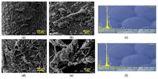

Figure 3.
The secondary electron image (SEI) of morphologies and the corresponding EDS spectra of Sn-Pd electrocatalysts obtained by electrodeposition of Pd on the Sn dendrites electrodeposited at the cathodic potentials of (a–c) −1200 mV, (d–f) −1400 mV, (g–i) −1600 mV and (j–l) −1800 mV. Pd was electrodeposited at a current density of −5 mA cm−2.
EDS analysis of the obtained deposits confirmed electrodeposition of Pd on Sn electrodes (Figure 3c,f,i,l).
To prove the partial coverage of Sn by electrodeposited Pd, mapping of all elements of the Sn-Pd electrocatalysts was performed, and the obtained results are shown in Figure 4.
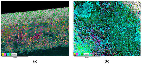

Figure 4.
Element mapping by EDS showing the spatial distribution of Sn-Pd electrocatalysts obtained by electrodeposition of Pd on the Sn dendrites electrodeposited at cathodic potentials of (a) −1200 mV, (b) −1400 mV, (c) −1600 mV, and (d) −1800 mV. Pd was electrodeposited at a current density of −5 mA cm−2.
3.2. Effect of Morphology of Sn Dendrite used as a Sub-Layer on Electrocatalytic Activity of Sn-Pd Electrocatalysts
The electrocatalysts synthesized via the electrodeposition route through two steps are denoted as Sn1-Pd, Sn2-Pd, Sn3-Pd and Sn4-Pd for Sn electrodeposited at −1200 mV, −1400 mV, −1600 mV and −1800 mV, respectively. The bimetallic composition with an atomic ratio of 60 at. % Sn–40 at. % Pd was constant, and the prepared electrocatalysts were tested for the EOR, as was presented in Figure 5a.

Figure 5.
(a) CVs of Sn1-Pd, Sn2-Pd, Sn3-Pd and Sn4-Pd catalysts in 1 M NaOH +1 M C2H5OH solution recorded at v = 50 mV s−1, and (b) CO stripping on Sn1-Pd, Sn2-Pd, Sn3-Pd and Sn4-Pd catalysts in 1 M NaOH solution recorded at v = 50 mV s−1.
All investigated Sn-Pd catalysts showed two anodic peaks for the EOR at ~−200 mV in the forward scan and at −350 mV in the backward scan. The peak observed in the forward scan can be ascribed to the oxidation of chemisorbed species coming from ethanol adsorption on the surface of the catalyst in the presence of adsorbed OH− species [9,13,15]. At more positive potentials, the reaction current drops because of Pd oxidation and a diminution of the number of surface active sites [39]. The peak in the backward scan is a consequence of the oxidation of carbonaceous species that are not completely oxidized in the forward scan.
Among the CVs at the investigated Sn-Pd catalysts for the EOR, the most active one was found to be Sn2-Pd produced by Sn electrodeposition at −1400 mV, with the current densities of the forward peak being 1.9, 2 and 2.5 times higher than those for Sn3-Pd, Sn4-Pd and Sn1-Pd, respectively (Figure 5a). The ratio of the forward peak current density (jf) and the backward peak current density (jb), jf/jb, serves to establish the poisoning tolerance of Pd catalysts to carbonaceous species [24,40] in terms of the efficiency of the oxidation of the EOR achieved at the higher ratio of jf/jb. The obtained values for jf/jb are 1.8, 1.6, 1.5, 1.2 for Sn2-Pd, Sn3-Pd, Sn4-Pd and Sn1-Pd, respectively. Among the investigated Sn-Pd catalysts, the most poison-tolerant was Sn2-Pd. At the same time, a negatively shifted onset potential of ∼50 mV was observed on Sn2-Pd in comparison to the other Sn-Pd catalysts, indicating that Sn2-Pd is more favorable for use in the EOR. CO stripping was used to evaluate the antipoisoning capability of the electrocatalyst surfaces, and the obtained results are presented in Figure 5b. According to CO stripping measurements, Sn2-Pd exhibited the lowest onset potential and current peak potential, indicating the highest antipoisoning capability among all investigated bimetallic electrocatalysts.
In order to investigate the stability of Sn-Pd electrocatalysts during the EOR, chronoamperometric measurements were performed at E = −400 mV, as shown in Figure 6. The dependencies of the current density with time decreased rapidly at the very beginning due to the accumulation of strongly adsorbed reaction intermediates on the surface active sites [39]. Subsequently, the current density gradually declined with time and reached a pseudosteady state. After 20 min, the activity of the EOR in terms of the current density followed the order Sn2-Pd > Sn3-Pd > Sn4-Pd > Sn1-Pd, which is in agreement with the results obtained for the CV measurements (Figure 5a). In particular, the Sn2-Pd electrocatalyst had a ~2 times higher current density than the other investigated Sn-Pd electrodes after the 20 min reaction. Comparing the initial and final states of the electrocatalysts in terms of chronoamperometric measurements (Figure 6), the current lost for the Sn1-Pd, Sn2-Pd, Sn3-Pd and Sn4-Pd electrocatalysts was 5.3, 4.4, 4.9 and 5.1 times, respectively. It was shown that Sn2-Pd still exhibited the slowest decay and consequently the highest stability among the investigated catalysts.

Figure 6.
Chronoamperograms of Sn1-Pd, Sn2-Pd, Sn3-Pd and Sn4-Pd electrocatalysts in 1 M NaOH +1 M C2H5OH solution recorded at E = −400 mV.
Among the Sn-Pd electrocatalysts with the constant atomic ratio of 60 at.% Sn-40 at.% Pd that were the subject of this investigation, Sn2-Pd was selected for the surface chemical composition and the oxidation state of elements analyses by X-ray photoelectron spectroscopy (XPS). Figure 7a shows the XPS survey spectrum of Sn2-Pd obtained for binding energies between 1000 and 0 eV. As expected, it shows the presence of Cu and O as substrate constituents and Sn, Pd and O resulting from the electrodeposition process. Additionally, traces of C originating from the adsorbed carbon impurities and Cl originating most likely from the electrodepositing solutions were identified. Atomic percentages obtained from the survey spectrum clearly indicated that the surface composition of Sn and Pd has a 60:40 ratio. Figure 7b shows the high-resolution XPS spectrum of Sn 3d, with a characteristic doublet originating from Sn 3d 3/2 and Sn 3d 5/2, each deconvoluted into two peaks. Peaks located at 495.3 eV and 486.8 eV can be assigned to Sn4+, originating from the SnO2 oxide, while the two peaks located at 493.7 eV and 485.2 eV are attributed to metallic Sn0. Sn is mostly oxidized by atmospheric air, with a small amount remaining in the metallic state [18,20,27,41,42,43]. Figure 7c shows the high-resolution spectrum of Pd 3d. A characteristic doublet consisting of Pd 3d 3/2 and Pd 3d 5/2 lines, each deconvoluted into two components, can be seen. Components at 340.8 eV and 335.5 eV are assigned to Pd0, while the other two at 341.5 eV and 336.5 eV correspond to Pd2+ and can be attributed to PdO, originating from Pd oxidized in the air. All Pd 3d peaks show an upshift of approximately 0.5 eV, which indicates that the presence of Sn affects the electronic state of Pd by reducing the adsorption strength of the reaction intermediates on Pd, which has a positive effect on its electrocatalytic activity during the EOR [18,20,27,41,42,43].

Figure 7.
The XPS spectra of the Sn2-Pd electrocatalyst: (a) the survey spectrum, (b) high-resolution spectrum of Sn 3d and (c) high-resolution spectrum of Pd 3d.
4. Discussion
From Figure 5a, it is obvious that the surface morphology of Sn, when used as a sub-layer, correlates with the electrocatalytic activity of the examined Sn-Pd electrocatalysts. The highest activity during the EOR showed the Sn-Pd electrocatalyst was obtained by Pd electrodeposition on Sn dendrites produced at a cathodic potential of −1400 mV (Sn2-Pd; Figure 5a), at which individual fern-like dendrites were formed. The higher activity of this electrocatalyst relative to all other electrocatalysts (Sn1-Pd, Sn3-Pd and Sn4-Pd) can be explained by morphological analysis of Sn dendrites produced at various cathodic potentials. The individual non-branching dendrites with spear-like and needle-like shapes were formed at a cathodic potential of −1200 mV, and no significant increase in the initial electrode surface area was seen. On the other hand, the high nucleation rate and dendritic growth from one nucleation center in more directions led to networking of the dendrites during electrodeposition at the cathodic potentials of −1600 and −1800 mV; thus, the appearance of the produced Sn electrodes approached that of compact massive Sn.
To prove this statement, the obtained Sn-Pd electrocatalysts were compared with that obtained by Sn electrodeposition at a cathodic potential of −1183 mV, corresponding to the very beginning of the electrodeposition process [35]. The granular non-dendritic electrodeposit was obtained at this cathodic potential (Figure 8a,b). EDS analysis confirmed the formation of pure Sn by this electrodeposition process (Figure 8c). The morphology and corresponding EDS spectrum of the Sn-Pd electrocatalyst obtained by Pd electrodeposition on an as-prepared Sn electrode are shown in Figure 8d–f, while the mapping of elements of this electrocatalyst is shown in Figure 8g. Similar to the electrodeposition processes at the higher cathodic potentials, the partial coverage of Sn by electrodeposited Pd was achieved. Please note that the compact Pd islands, which were very similar to each other, were obtained by the electrodeposition processes at −1183 and −1800 mV.
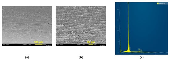

Figure 8.
The secondary electron image (SEI) of morphologies and EDS spectra of Sn and Sn-Pd deposits obtained by the electrodeposition processes: (a–c) Sn; E = −1183 mV; (d–f) Sn-Pd; (g) element mapping with spatial distribution of elements obtained for SEI image of Sn-Pd deposit. Pd was electrodeposited at a current density of −5 mA cm−2 on the Sn electrode shown under (a,b).
The bimetallic Sn-Pd electrocatalyst formed by the two-step electrochemical method with Sn electrodeposited at −1183mV is denoted as Sn5-Pd and was also examined in the EOR, as shown in Figure 9a. CO stripping for this electrocatalyst was also carried out, and the obtained result is shown in Figure 9b. For the sake of comparison, the Sn2-Pd electrocatalyst with the highest electrocatalytic activity is also included in Figure 9.

Figure 9.
(a) CVs of Sn2-Pd and Sn5-Pd electrocatalyst in 1 M NaOH +1 M C2H5OH solution recorded at v = 50 mV s−1, and (b) CO stripping on Sn2-Pd and Sn5-Pd electrocatalysts in 1 M NaOH solution recorded at v = 50 mV s−1.
Comparing the CVs from Figure 5a and Figure 9a, it is obvious that the electrocatalyst constructed from the granular non-dendritic Sn deposit (Sn5-Pd) showed the lowest electrocatalytic activity. This clearly proves that the morphology of Sn as a sub-layer has a crucial role in the electrocatalytic performances of Sn-Pd electrocatalysts. The individual fern-like dendrites produced at −1400 mV (Sn2-Pd) probably provide more Pd active sites accessible to the EOR than the Sn dendrites produced at the other cathodic potentials. In this way, better utilization of Pd on the Sn2-Pd electrocatalyst than on any of the other types of electrocatalysts is enabled. In order to measure the intrinsic activities of the investigated electrocatalysts, a CO stripping test (Figure 5b and Figure 9b) was used to evaluate the electrochemically active surface area (ECSA). The calculated ECSA for Sn1-Pd, Sn2-Pd, Sn3-Pd, Sn4-Pd and Sn5-Pd was 41.4 m2 gPd−1, 65.2 m2 gPd−1, 46 m2 gPd−1, 44.6 m2 gPd−1 and 34.5 m2 gPd−1, respectively, which indicates that the Sn2-Pd catalyst exhibited the highest ECSA among the synthesized catalysts. The normalized forward peak current densities by ECSAs for Sn1-Pd, Sn2-Pd, Sn3-Pd, Sn4-Pd and Sn5-Pd were found to be 0.17 mA cm−2, 0.27 mA cm−2, 0.20 mA cm−2, 0.18 mA cm−2 and 0.155 mA cm−2, respectively. Sn2-Pd still exhibited the highest specific current density.
In previously published papers [20,21,29], the content of Sn in Pd-Sn electrocatalysts was varied and discussed in view of the surface activity in the EOR, showing better electrocatalytic performances with higher contents of Pd in bimetallic catalysts. For the first time, in this study, an influence of the surface morphology of Sn as a sub-layer in the Sn-Pd system was examined, and correlations among Sn surface morphology, utilization of Pd and the electrocatalytic activities of bimetallic Sn-Pd electrocatalysts in the EOR have been established. Nevertheless, in the examined bimetallic catalysts, Pd (40%) covered Sn (60%) and the content of Pd was reduced, thereby lowering the cost of electrocatalysts, which is important for possible practical application.
The electrochemical behavior concerning the EOR obtained for the Sn2-Pd electrocatalyst was also compared with Pd electrocatalysts obtained by electrodeposition of Pd on the Cu substrate (Figure 10a). The completely different shapes of the CVs can be seen in Figure 10a. The presence of Sn in the electrocatalyst resulted in a shift in the onset potential to more negative potentials of approximately 200 mV compared to Pd, improving the kinetics of the EOR. The current maximum of Sn2-Pd is 3.5 times higher than that of Pd alone, and it appears at a lower potential for more than 100 mV, indicating higher oxidation efficiency for intermediate species adsorbed on the bimetallic catalyst.

Figure 10.
(a) CVs of Sn2-Pd and Pd in 1 M NaOH +1 M C2H5OH solution, and (b) CVs of Pd and Sn (in inset) in 1 M NaOH +1 M C2H5OH solution and Cu in 1 M NaOH. All CVs were recorded at v = 50 mV s−1.
Additionally, it is clear that the features of CV for the EOR are strongly influenced by the Cu substrate used as a catalyst support. In order to explain the obtained features of CV for the EOR on a Pd electrode, additional experiments were performed and are presented in Figure 10b. The CV of the Cu electrode in the solution without ethanol overlapped with the CV of the Pd electrode in the presence of ethanol in the solution, showing that the Cu substrate affected Pd activity, and as a consequence, during the forward scan, one broad oxidation peak can be seen, while in the backward scan, no oxidation current is observed. Instead, two reduction peaks at −300 mV and −420 mV are formed due to the reduction in carbon containing-species, facilitated by the Cu surface oxides [44]. Electrodeposited Sn is inactive for the EOR in the investigated potential region, as shown in the inset of Figure 10b. Therefore, metallic Sn does not contribute individually to the EOR. Nevertheless, in Sn-Pd electrocatalysts, Sn promotes the formation of OHad and enhances the EOR activity by removing the carbonaceous intermediates adsorbed on Pd sites [19,20]. Therefore, the enhancement in the catalytic activity of the Sn-Pd electrocatalysts compared to that of Pd alone can be attributed to Sn’s morphological characteristics and bifunctional effect.
The activity achieved for Sn2-Pd in the EOR is higher than that seen for commercial Pd1-Sn0.5/C [41] but comparable to that obtained on hierarchical PdSn alloy nanosheet dendrites [45], followed by Pd-impregnated normal SnO2 nanowire [30] and a PdSn electrocatalyst supported on activated biocarbon [46]. In addition, a comparison of the EOR performances obtained on deposited Sn-Pd electrocatalysts with other literature data, such as those for commercial Pd/C [3,19,28] or synthesized Pd nanocatalysts [18,20,47] and PdSn nanocatalysts [24,25,26,29,41], depicted lower activity. For that reason, some improvement should be considered, such as the fabrication of Pd nanoparticles over Sn or the addition of metal oxides.
5. Conclusions
This work provides a novel procedure for the preparation of Sn-Pd electrocatalysts by a two-step electrodeposition processes. Electrodeposition of Sn at different cathodic potentials was followed by electrodeposition of Pd at a constant current density, keeping the constant atomic ratio of 60 at. % Sn–40 at. % Pd. Depending on the applied cathodic potential, various forms of Sn dendrites were formed, including: needle-like, spear-like and fern-like dendrites and a network of intertwined dendrites of the fern-like shape. Partial coverage of the Sn dendrites was achieved by Pd electrodeposition.
A strong correlation between the morphology of the Sn dendrites as a sub-layer and the electrocatalytic activity of Sn-Pd electrocatalysts towards the ethanol oxidation reaction (EOR) was established. The largest electrocatalytic activity was shown by the Sn-Pd electrocatalyst constructed from the individual fern-like Sn dendrites, clearly indicating that the type of dendrite and degree of its branching also play important roles in the electrocatalytic activity of the electrocatalysts. Additionally, this dendrite type provided the largest electrochemical active surface area of Pd. This conclusion was derived by a comparison of the electrocatalytic activity of the electrocatalysts with those obtained on Pd electrodeposited on the Cu electrode without Sn as a sub-layer and Sn-Pd electrocatalysts synthesized by electrodeposition of Pd on a non-dendritic granular Sn deposit. Aside from the morphological contribution of Sn as a sub-layer to the electrocatalytic activity, the improvement in the electrocatalytic performances of Sn-Pd electrocatalysts is also attributed to the bifunctional effect.
Author Contributions
Conceptualization, N.D.N. and J.D.L. methodology, N.D.N. and J.D.L.; validation, N.D.N., J.D.L. and N.L.I.; investigation, N.D.N., J.D.L., S.E.P., S.B.D., L.Z.R. and N.L.I.; resources, N.D.N., L.Z.R. and J.D.L.; writing—original draft preparation, N.D.N., L.Z.R. and J.D.L.; writing—review and editing, N.D.N., J.D.L. and N.L.I.; visualization, N.D.N.; supervision, N.D.N.; funding acquisition, N.D.N. All authors have read and agreed to the published version of the manuscript.
Funding
This work was supported by the Ministry of Science, Technological Development and Innovation of the Republic of Serbia (RS) (Grant No. 451-03-68/2022-14/200026, 451-03-68/2022-14/200175 and 451-03-68/2022-14/200052) and the Science Fund of RS (Grant No. AdCatFC: 7739802).
Data Availability Statement
The data presented in this study are available on request from the corresponding author or co-authors. The data are not publicly available.
Acknowledgments
This work was supported by the Ministry of Science, Technological Development and Innovation of the Republic of Serbia (RS) and Science Fund of RS.
Conflicts of Interest
The authors declare no conflict of interest.
References
- Bianchini, C.; Shen, P.K. Palladium-Based Electrocatalysts for Alcohol Oxidation in Half Cells and in Direct Alcohol Fuel Cells. Chem. Rev. 2009, 109, 4183–4206. [Google Scholar] [CrossRef]
- Halim, E.M.; Chemchoub, S.; El Attar, A.; Salih, F.E.; Oularbi, L.; El Rhazi, M. Recent Advances in Anode Metallic Catalysts Supported on Conducting Polymer-Based Materials for Direct Alcohol Fuel Cells. Front. Energy Res. 2022, 10, 843736. [Google Scholar] [CrossRef]
- Selepe, C.T.; Gwebu, S.S.; Matthews, T.; Mashola, T.A.; Sikeyi, L.L.; Zikhali, M.; Maxakato, N.W. Effect of Sn Doping on Pd Electro-Catalysts for Enhanced Electro-Catalytic Activity towards Methanol and Ethanol Electro-Oxidation in Direct Alcohol Fuel Cells. Nanomaterials 2021, 11, 2725. [Google Scholar] [CrossRef] [PubMed]
- Elsaid, K.; Abdelfatah, S.; Elabsir, A.M.A.; Hassiba, R.J.; Ghouri, Z.K.; Vechota, L. Direct alcohol fuel cells: Assessment of the fuel’s safety and health aspects. Int. J. Hydrogen Energy 2021, 46, 30658–30668. [Google Scholar] [CrossRef]
- Zhao, G.; Fang, C.; Hu, J.; Zhang, D. Platinum-Based Electrocatalysts for Direct Alcohol Fuel Cells: Enhanced Performances toward Alcohol Oxidation Reactions. ChemPlusChem 2021, 86, 574–586. [Google Scholar] [CrossRef] [PubMed]
- Antolini, E.; Gonzales, E.R. Alkaline direct alcohol fuel cells. J. Power Sources 2010, 195, 3431–3450. [Google Scholar] [CrossRef]
- Pech-Rodríguez, W.J.; González-Quijano, D.; Vargas-Gutiérrez, G.; Morais, C.; Napporn, T.W.; Rodríguez-Varela, F.J. Electrochemical and in situ FTIR study of the ethanol oxidation reaction on PtMo/C nanomaterials in alkaline media. Appl. Catal. B-Environ. 2017, 203, 654–662. [Google Scholar] [CrossRef]
- Liang, Z.; Song, L.; Deng, S.; Zhu, Y.; Stavitski, E.; Adzic, R.R.; Chen, J.; Wang, J.X. Direct 12-electron oxidation of ethanol on a ternary Au(core)-PtIr (Shell) electrocatalyst. J. Am. Chem. Soc. 2019, 141, 9629–9636. [Google Scholar] [CrossRef]
- Dutta, A.; Mondal, A.; Broekmann, P.; Datta, J. Optimal level of Au nanoparticles on Pd nanostructures providing remarkable electro-catalysis in direct ethanol fuel cell. J. Power Sources 2017, 361, 276–284. [Google Scholar] [CrossRef]
- Paiva, V.M.; Assis, K.L.D.S.C.; Archanjo, B.S.; Ferreira, D.R.; Senna, C.A.; Ribeiro, E.S.; Achete, C.A.; D’Elia, E. Electrochemical Analysis of Free Glycerol in Biodiesel Using Reduced Graphene Oxide and Gold/Palladium Core-Shell Nanoparticles Modified Glassy Carbon Electrode. Processes 2021, 9, 1389. [Google Scholar] [CrossRef]
- Lovic, J.D.; Elezovic, N.R.; Jovic, B.M.; Zabinski, P.; Gajic-Krstajic, L.j.; Jovic, V.D. Electrodeposited AgPd alloy coatings as efficient catalysts for the ethanol oxidation reaction. Int. J. Hydrogen Energy 2018, 43, 18498–18508. [Google Scholar] [CrossRef]
- Jadali, S.; Kamyabi, M.A.; Solla-Gullón, J.; Herrero, E. Effect of Pd on the electrocatalytic activity of Pt towards oxidation of ethanol in alkaline solutions. Appl. Sci. 2021, 11, 1315. [Google Scholar] [CrossRef]
- Lovic, J.D.; Jovic, V.D. Electrodeposited Pd and PdNi coatings as electrodes for the electrochemical oxidation of ethanol in alkaline media. J. Solid State Electrochem. 2017, 21, 2433–2441. [Google Scholar] [CrossRef]
- Yun, Q.; Lu, Q.; Li, C.; Chen, B.; Zhang, Q.; He, Q.; Hu, Z.; Zhang, Z.; Ge, Y.; Yang, N. Synthesis of PdM (M = Zn, Cd, ZnCd) nanosheets with an unconventional face-centered tetragonal phase as highly efficient electrocatalysts for ethanol oxidation. ACS Nano 2019, 13, 14329–14336. [Google Scholar] [CrossRef] [PubMed]
- Moura Souza, F.; Nandenha, J.; Batista, B.L.; Oliveira, V.H.A.; Pinheiro, V.S.L.; Parreira, S.; Neto, A.O.; Santos, M.C. PdxNby electrocatalysts for DEFC in alkaline medium: Stability, selectivity and mechanism for EOR. Int. J. Hydrogen Energy 2018, 43, 4505–4516. [Google Scholar] [CrossRef]
- Xu, C.; Shen, P.K.; Liu, Y. Ethanol electrooxidation on Pt/C and Pd/C catalysts promoted with oxide. J. Power Sources 2007, 164, 527–531. [Google Scholar] [CrossRef]
- Abdel Hammed, R.M. Facile preparation of Pd-metal oxide/C electrocatalysts and their application in the electrocatalytic oxidation of ethanol. Appl. Surf. Sci. 2017, 411, 91–104. [Google Scholar] [CrossRef]
- Cao, Z.; Liu, X.; Meng, X.; Cai, L.; Chen, J.; Guo, P. Synthesis of bimetallic PdSn nanoparticle assembly as highly efficient electrocatalyst for ethanol oxidation. Colloids Surf. A 2021, 621, 126577. [Google Scholar] [CrossRef]
- Pinheiro, V.S.; Souza, F.M.; Gentil, T.C.; Nascimento, A.N.; Bohnstedt, P.; Parreira, L.S.; Paz, E.C.; Hammer, P.; Sairre, M.I.; Batista, B.L.; et al. Sn-containing electrocatalysts with a reduced amount of palladium for alkaline direct ethanol fuel cell applications. Renew. Energy 2020, 158, 49–63. [Google Scholar] [CrossRef]
- Makin Adam, A.M.; Zhu, A.; Ning, L.; Deng, M.; Zhang, Q.; Liu, Q. Carbon supported PdSn nanocatalysts with enhanced performance for ethanol electrooxidation in alkaline medium. Int. J. Hydrogen Energy 2019, 44, 20368–20378. [Google Scholar] [CrossRef]
- Du, W.; Mackenzie, K.E.; Milano, D.F.; Aaron Deskins, N.; Su, D.; Teng, X. Palladium−Tin Alloyed Catalysts for the Ethanol Oxidation Reaction in an Alkaline Medium. ACS Catal. 2012, 2, 287–297. [Google Scholar] [CrossRef]
- Zhang, Y.; Yi, Q.; · Deng, Z.; Zhou, X.; Nie, H. Excellent electroactivity of ternary Pd–Ag–Sn nanocatalysts for ethanol oxidation. Catal. Lett. 2018, 148, 1190–1201. [Google Scholar] [CrossRef]
- Mao, H.; Wang, L.; Zhu, P.; Xu, Q.; Li, Q. Carbon-supported PdSn-SnO2 catalyst for ethanol electro-oxidation in alkaline media. Int. J. Hydrogen Energy 2014, 39, 17583–17588. [Google Scholar] [CrossRef]
- Ning, L.; Liu, X.; Deng, M.; Huang, Z.; Zhu, A.; Zhang, Q.; Liu, Q. Palladium-based nanocatalysts anchored on CNT with high activity and durability for ethanol electro-oxidation. Electrochim. Acta 2019, 297, 206–214. [Google Scholar] [CrossRef]
- Zhang, B.; Zhang, X.; Yan, J.; Cao, Z.; Pang, M.; Chen, J.; Zang, L.; Guo, P. Synthesis of free-standing alloyed PdSn nanoparticles with enhanced catalytic performance for ethanol electrooxidation. ChemElectroChem 2021, 8, 4509–4514. [Google Scholar] [CrossRef]
- Zhou, M.; Liu, J.; Ling, C.; Ge, Y.; Chen, B.; Tan, C.; Fan, Z.; Huang, J.; Chen, J.; Liu, Z.; et al. Synthesis of Pd3Sn and PdCuSn Nanorods with L12 Phase for Highly Efficient Electrocatalytic Ethanol Oxidation. Adv. Mater. 2022, 34, 2106115. [Google Scholar] [CrossRef]
- You, H.; Gao, F.; Wang, C.; Li, J.; Zhang, K.; Zhang, Y.; Du, Y. Rich grain boundaries endow networked PdSn nanowires with superior catalytic properties for alcohol oxidation. Nanoscale 2021, 13, 17939–17944. [Google Scholar] [CrossRef]
- Song, T.; Gao, F.; Zhang, Y.; Yu, P.; Wang, C.; Shiraishi, Y.; Li, S.; Wang, C.; Guo, J.; Du, Y. Shape-controlled PdSn alloy as superior electrocatalysts for alcohol oxidation reactions. J. Taiwan Inst. Chem. Eng. 2019, 101, 167–176. [Google Scholar] [CrossRef]
- Huang, J.; Ji, L.; Li, X.; Wu, X.; Qian, N.; Li, J.; Yan, Y.; Yang, D.; Zhang, H. Facile synthesis of PdSn alloy octopods through the Stranski–Krastanov growth mechanism as electrocatalysts towards the ethanol oxidation reaction. CrystEngComm 2022, 24, 3230–3238. [Google Scholar] [CrossRef]
- Ho Lee, S.; Jo, Y.-R.; Noh, Y.; Kim, B.-J.; Bae Kim, W. Fabrication of hierarchically branched SnO2 nanowires by two-step deposition method and their applications to electrocatalyst support and Li ion electrode. J. Power Sources 2017, 367, 1–7. [Google Scholar] [CrossRef]
- Liu, S.; Wang, L. Controlled Preparation of Different Proportions of Metal Fe-Mn from Waste Mn Ferrite by Molten Salt Electrolysis. Processes 2020, 8, 1647. [Google Scholar] [CrossRef]
- Qi, Y.; He, C.; Zhang, R.; Wang, W. Analysis of Fe(II)-Ni(II) Electrochemical Reduction Process and Electrodeposition of FeNi Films. Processes 2022, 10, 198. [Google Scholar] [CrossRef]
- Lv, S.; Shang, W.; Chi, Y.; Wang, H.; Chu, X.; Geng, P.; Wang, C.; Yang, J.; Cheng, Z.; Yang, X. Hierarchical Design of Co(OH)2/Ni3S2 Heterostructure on Nickel Foam for Energy Storage. Processes 2022, 10, 1255. [Google Scholar] [CrossRef]
- El Sayed, M.A.; Ibrahim, M.A.M.; Elazab, N.T.; Gassoumi, M. Electrochemical Synthesis of Nanocrystalline CuAg Coatings on Stainless Steel from Cyanide-Free Electrolyte. Processes 2022, 10, 2134. [Google Scholar] [CrossRef]
- Nikolić, N.D.; Lović, J.D.; Maksimović, V.M.; Živković, P.M. Morphology and structure of electrolytically synthesized tin dendritic nanostructures. Metals 2022, 12, 1201. [Google Scholar] [CrossRef]
- Popov, K.I.; Nikolić, N.D. General Theory of Disperse Metal Electrodeposits Formation. In Electrochemical Production of Metal Powders (Ser. Mod. Asp. Electrochem.); Djokić, S.S., Ed.; Springer International Publishing: New York, NY, USA, 2012; pp. 1–62. [Google Scholar]
- Diggle, J.W.; Despic, A.R.; Bockris, J.M. The Mechanism of the Dendritic Electrocrystallization of Zinc. J. Electrochem. Soc. 1969, 116, 1503–1514. [Google Scholar] [CrossRef]
- Popov, K.I.; Djokić, S.S.; Nikolić, N.D.; Jović, V.D. Morphology of Electrochemically and Chemically Deposited Metals; Springer: New York, NY, USA, 2016; pp. 1–368. [Google Scholar] [CrossRef]
- Hasan, M.; Khunsin, W.; Mavrokefalos, C.K.; Maier, S.A.; Rohan, J.F.; Foord, J.S. Facile electrochemical synthesis of Pd nanoparticles with enhanced electrocatalytic properties from surfactant-free electrolyte. ChemElectroChem 2018, 5, 619–629. [Google Scholar] [CrossRef]
- Lee, Y.-W.; Han, S.-B.; Park, K.-W. Electrochemical properties of Pd nanostructures in alkaline solution. Electrochem. Commun. 2009, 11, 1968–1971. [Google Scholar] [CrossRef]
- Liu, X.; Wang, X.; Wu, J.; Zhu, A.; Zhang, Q.; Liu, Q. Synergy effects between Sn and SiO2 on enhancing the anti-poison ability to CO for ethanol electrooxidation. Electrochim. Acta 2019, 302, 145–152. [Google Scholar] [CrossRef]
- Ye, N.; Zhao, P.; Qi, X.; Jiang, Z.; Fang, T. Ethanol electro-oxidation on the PdSn-TaN/C catalyst in alkaline media: Making TaN capable of splitting C-C bond. Appl. Catal. B-Environ. 2022, 314, 121473. [Google Scholar] [CrossRef]
- Gao, K.; Mou, T.; Liu, S.; Johnson, G.; Han, X.; Yan, Z.; Ji, M.; He, Q.; Zhang, S.; Xin, H.; et al. Monodisperse PdSn/SnOx core/shell nanoparticles with superior electrocatalytic ethanol oxidation performance. J. Mater. Chem. A 2020, 8, 20931. [Google Scholar] [CrossRef]
- Prabhuram, J.; Manoharan, R.; Vasan, H.N. Effects of incorporation of Cu and Ag in Pd on electrochemical oxidation of methanol in alkaline solution. J. Appl. Electrochem. 1998, 28, 935–941. [Google Scholar] [CrossRef]
- Ding, L.-X.; Wang, A.-W.; Ou, Y.-N.; Li, Q.; Guo, R.; Zhao, W.-X.; Tong, Y.-X.; Li, G.-R. Hierarchical Pd-Sn alloy nanosheet dendrites: An economical and highly active catalyst for ethanol electrooxidation. Sci. Rep. 2013, 3, 1181. [Google Scholar] [CrossRef]
- da Silva, E.L.; Cuna, A.; Cadorin, M.; Marcuzzo, J.S.; Radtke, C.; Baldan, M.R.; Rodrigues-Siqueli, A.C.; de Fraga Malfatti, C. Influence of the support and SnO2 content on the electrocatalytic properties of PdSn/C electrocatalysts for EOR in alkaline medium. Waste Biomass Valorization 2022, 13, 1705–1716. [Google Scholar] [CrossRef]
- Li, S.; Shu, J.; Ma, S.; Yang, H.; Jin, J.; Zhang, X.; Jin, R. Engineering three-dimensional nitrogen-doped carbon black embed-ding nitrogen-doped graphene anchoring ultrafine surface-clean Pd nanoparticles as efficient ethanol oxidation electrocatalyst. Appl. Catal. B-Environ. 2021, 280, 119464. [Google Scholar] [CrossRef]
Disclaimer/Publisher’s Note: The statements, opinions and data contained in all publications are solely those of the individual author(s) and contributor(s) and not of MDPI and/or the editor(s). MDPI and/or the editor(s) disclaim responsibility for any injury to people or property resulting from any ideas, methods, instructions or products referred to in the content. |
© 2023 by the authors. Licensee MDPI, Basel, Switzerland. This article is an open access article distributed under the terms and conditions of the Creative Commons Attribution (CC BY) license (https://creativecommons.org/licenses/by/4.0/).