Abstract
Due to the opaqueness of rock and the limitation of detection technology, it is impossible to accurately describe the crack growth process and determine the law of rock breakage. Based on smoothed particle hydrodynamics and the finite element method (SPH-FEM), a numerical model for high-speed water jet breaking was established in this work to simulate the fragmentation process of rock impacted by a high-speed water jet, and to study the effects of different jet angles on the propagation of microscopic cracks inside the rock. Additionally, we further analyzed the jet impact angle on the microscopic crack propagation trend of the rock by applying confining pressure to the rock. Theoretical and experimental analyses showed that the inclination angle of the jet determined the direction of axial crack propagation in the tension-type center. When the inclination angle of the jet exceeded 20°, the ability of water jet erosion was insufficient, and the efficiency of rock fragmentation was low. However, in the range of 15° to 20°, the capacity of erosion was strong, lamellar crack propagation was obvious, and rock chip block spalling was easily produced. The impact of the water jet on the rock at varying angles under rock confining pressure will make the crack propagation direction deviate from the direction without confining pressure and gradually become parallel to the rock plane, thereby promoting unilateral crack propagation in the direction of water jet impact, making the rock more likely to produce unilateral rock chip spalling.
1. Introduction
In recent years, high-pressure water jet technology has been widely used in deep drilling, coal mining, urban underground engineering, and other fields as a non-contact rock-breaking method with many advantages, such as high efficiency, a lack of dust, no vibrations, and no electrical sparks [1,2,3]. Rock fragmentation under the action of high-speed water jet impacts is a nonlinear impact dynamics problem involving a variety of complex factors. The characteristics of an instantaneous strong-value dynamic load, large deformation, and high strain rate make it difficult to explain rock impact fragmentation behavior [4]. Therefore, it is of great engineering value and scientific significance to study the impact of crack propagation on rock fragmentation under the impact of high-speed water jets.
Jiang et al. [5] used a numerical method combining the finite element method and smooth particle hydrodynamics to study rock fragmentation under water jet impact loading and its influencing factors, revealing that rock impact fragmentation under the action of a water jet is the result of the joint action of tensile and shear damage. Yu et al. [6] studied the effect of water jet incidence parameters on the dynamic responses and damage behavior of concrete materials based on the effects of water jet incidence parameters on the dynamic responses and damage behaviors of concrete materials; the critical velocity of a constant diameter jet necessary to produce lateral cracks inside concrete was also determined. Li et al. [7] used scanning electron microscopy to observe the fracture morphology of water jet cut rocks, analyzed the microscopic damage mechanism of rocks under the action of ultra-high-pressure jets, and established a bridge between the microscopic damage mechanisms of rocks and macroscopic fracture analysis. Wu et al. [8] used the Voronoi subdivision technique to simulate the mechanical interaction between particles and the fracture processes of rocks and investigated the microstructural and mesomechanical properties of rocks under the impact of water jets on fracture performance. Oh et al. [9] studied the fracture characteristics of granite by changing different geometric parameters of water jets in a high-pressure water jet system. Sheng et al. [10] used scanning electron microscopy and three-dimensional reconstruction with computed tomography images to carry out water jet erosion-breaking experiments under submerged conditions, and analyzed the macroscopic damage processes and microscopic damage morphological characteristics of rocks. Xue et al. [11,12] simulated the propagation of stress waves in rocks under the action of pulsed water jets based on the numerical model of SPH, and the study showed that the stress propagation law and fracture characteristics are the keys to revealing the mechanism of water jet impact rock fragmentation.
The above-mentioned research has advanced the development of water jet rock-breaking theory. However, the opaqueness of rocks and the anisotropy of their internal structures make rock fragmentation laws complex and variable. Under the action of a water jet, the crack propagates slowly in rock. The purpose of this paper is to study the incremental fragmentation process within rock under the impact of high-speed water jets based on coupled FEM-SPH algorithm modeling, analyze the trend of fracture propagation in rock penetrated by jets at different angles, and further explore the propagation trend of cracking in rock under confining pressure. The study’s results will provide a sufficient theoretical basis for further revealing the mechanism underlying incremental crack breakage in rock under water jet impact loading.
2. Fluid-Solid Coupling Algorithm
The incremental fracture of rocks by high-speed water jets is a high-speed impact dynamics problem involving many factors, including both the high-speed flow impact of water jets and the stress wave response generated by the rock under this effect. Considering the difficulty of calculating large deformation problems via FEM, SPH has the inherent defects of tensile instability, difficulty in imposing boundary conditions, and low computational efficiency [13]. Therefore, the coupled SPH-FEM algorithm is used here to simulate the rock fracture fragmentation process due to the advantages of large deformation under SPH and high computational accuracy and efficiency under FEM, enabling us not only to obtain more accurate rock damage characteristics but also to better simulate the large instantaneous deformation and high strain rate in the impact process.
2.1. SPH Algorithm
The SPH method is a Lagrange particle method without meshing, which discretizes the computational domain into a series of particles interacting through kernel functions. By introducing the concepts of field and kernel functions, the nodes and cells of the mesh are replaced by smooth discrete particles; each SPH particle carries several physical quantities, which include velocity, mass, density, acceleration, etc. The SPH method is widely used in computational fluid and solid mechanics and offers great advantages in solving large deformation and collision problems [14]. The field function and its differential form at particle i are approximated as [15]:
where mj, ρi are the mass and density of particle j; is the value of the kernel function of particle j with respect to particle i; h is the smoothing length; and N is the total number of particles.
By discretizing the Navier–Stokes equation, the equation of fluid conservation under the SPH method becomes as follows [16]:
Conservation of mass:
Conservation of momentum:
Conservation of energy:
where and are the stress and strain tensor of particle i, respectively; p is the fluid pressure; is the coordinate of particle i in the direction of β; is the relative velocity between two particles in the direction of β; α, β stands for different axes; and μ is the viscosity coefficient of fluid.
2.2. SPH-FEM Coupling Contact Force Generation
The SPH-FEM contact coupling algorithm uses the potential contact gradient to define the contact force between the SPH particle and the finite element and relies on point and surface contact to achieve the calculations. In this paper, the point-surface contact algorithm is used to define the coupling between the water jet and the rock interface. The SPH particle are used as the slave nodes, and the control parameters are the node number, spatial position, and mass; the rock element of the finite element description is defined as the main surface. The implementation of the contact force between the SPH particle and the finite element reflects the idea of the meshless contact algorithm [17]; Figure 1 illustrates the implementation of the contact force between the SPH particle and the finite element form, where the smaller dashed circles represent the background particles at each finite element node, and the small solid circles represent SPH particles. The larger dashed circles represent the support domain range of SPH particle i, where the background particles out of the finite element nodes have only the properties of SPH particles passively searched by the actual SPH particles. By passing the information on the position, velocity, stress, and mass at the finite element nodes to the corresponding background particles, the SPH particles then search the adjacent finite element nodes in the same way as the background particles to further calculate the contact force applied on the SPH particles. A contact force is generated only when the distance between the SPH particles and the finite element nodes is twice the smooth length.
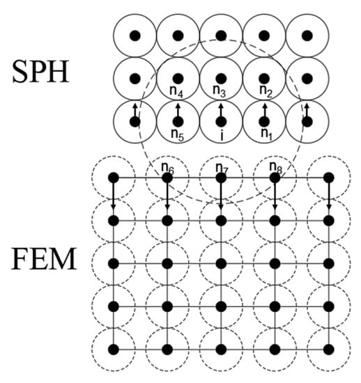
Figure 1.
SPH particles in contact with finite elements.
3. Computational Modeling and Validation
3.1. Water Jet Material Model
The water jet model for high-speed water jet impact rock breaking is described by the Grüneisen equation of state, and the expression for the pressure in the high-pressure water jet intrusion state is
where ρ0 is the initial density of water, and C and θ are the speed of the sound and volume strain, respectively; ; γ0 is the Grüneisen coefficient; a is the first-order volume correction to γ0; S1, S2 and S3 are the material constants of water; and E is the initial internal energy.
The parameters of the intrinsic model of water are shown in Table 1:

Table 1.
Parameters in the Grüneisen equation of state for water.
3.2. Rock Material Model
Under the high-speed impact load of a water jet, there will be a high-stress zone inside the rock, and plastic compression and shear failure caused by the closure of the original microcrack. To better describe the damage process of rock breakage, in this paper, the Johnson–Holmquist model II (JH-2) constitutive model of brittle materials is used to characterize the nonlinear impact dynamics of rock subjected to water jet penetration.
Herein, the polynomial equation of state (EOS) presents the relationship between hydrostatic pressure P and volumetric strain μ. Figure 2a, illustrates the pure elastic stage and a plastic damage stage [18]. The expressions are given by:
where K1, K2 and K3 are constants (K1 is the bulk modulus), ΔP is the increase in pressure over hydrostatic pressure, and μ is the volumetric strain.
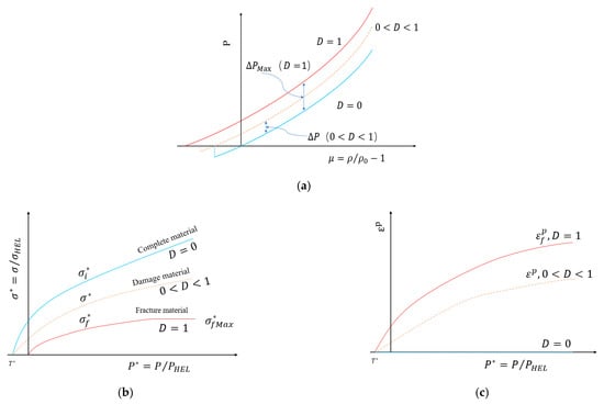
Figure 2.
(a) Material pressure model; (b) material strength model; (c) material damage model.
Figure 2b describes the strength curves of brittle materials based on three forms: intact state, damaged state, and fracture state. The three different forms have corresponding strength equations with normalized equivalent stress as:
When the rock damage factor is D = 0, the normalized equivalent stress is:
The normalized fracture equivalent stress when the rock damage factor is D = 1 is:
where is the normalized complete equivalent stress, is the normalized fracture stress, D is the damage factor (0 ≤ D ≤ 1), is the equivalent stress at the Hugoniot elastic limit, and σ is the actual equivalent stress calculated by the von Mises stress formula; A, B, C, M, N are the material constants, P* is the normalized equivalent pressure, and P* = P/PHEL, where P is the actual hydrostatic pressure, PHEL is the pressure when the rock is at the Hugoniot elastic limit, T* is the normalized maximum tensile hydrostatic pressure to which the rock is subjected, T* = T/PHEL, T is the maximum tensile hydrostatic pressure to which the rock material is subjected, is the dimensionless material strain rate, , is the actual equivalent strain rate, and is the reference strain rate.
According to the relationship between the equivalent plastic strain εp and the equivalent force P*, when D = 0, the rock is in the elastic state and not deformed plastically. When 0 < D < 1, the equivalent plastic strain of the material increased with an increase in the equivalent force, and the material strength decreased. When the equivalent plastic strain reaches the equivalent crushing plastic strain, the material was completely destroyed. As in Figure 2c, the JH-2 model damage corresponding to the nonlinear growth trend damage factor D can be expressed as:
where Δεp is the integral of the effective plastic strain within a single cycle, is the plastic strain of the equivalent rupture of the material, and D1, D2 are the damage parameters introduced by the model.
The rock samples used in this paper are granite materials. The mechanical properties of granite in different regions are more or less the same, and the above parameters can generally be obtained directly or indirectly. The JH-2 model parameters of granite materials are shown in Table 2.
Table 2.
JH-2 parameters of granite.
3.3. Geometric Model Description of Water Jet Impact Rock Breaking
The geometric modeling of the water jet rock-breaking process based on the above description is shown in Figure 3. The rock model is a simplified 80 × 60 mm planar rectangle, and the rock is divided into a grid of 100,000 elements using the finite element method. The SPH algorithm describes the water jet, and the simplified model of the 1.0 × 40 mm water jet is divided into 900 SPH particles. The non-reflective boundary is present on all surfaces except for the upper surface of the rock.
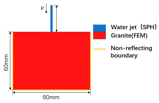
Figure 3.
Schematic diagram of water jet impinging on the rock.
3.4. Model Validation
To verify the validity of this numerical model, numerical simulations were conducted to compare against existing experimental studies. In the field experiment, the same parameters were used to continuously impact the rock with a jet, and the crushing of the rock due to damage was observed in the field experiment and the numerical simulation. To reduce the experimental errors, the crushing crater was filled with silicone, and the diameter of the crushing crater dc was about 5.80 mm. The crater depth hc was about 2.90 mm after the silicone was solidified, the diameter of the crushing crater in the numerical simulation was 5.661 mm, and the crater depth was 2.79 mm. Compared to Figure 4, it can be seen that the size and shape of the numerical simulation results are approximately consistent with those of the field experiment. This model will serve as the basis for subsequent research on rock fracturing under high-speed water jet impacts.
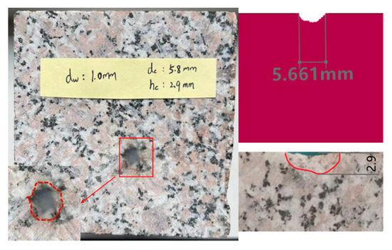
Figure 4.
Comparison of cavitation pit shape between the experiment and simulation.
4. Analysis of Results
4.1. Rock Fracturing Damage Process
The propagation of internal microscopic cracks and macroscopic fragmentation of the rock caused by the impact of the jet with time are shown in Figure 5, and for the convenience of data processing, the original data is scaled to the range of [0, 1] by linear normalization of the rock energy, as shown in Figure 6. In addition, it is specially noted that the description of time points in this section corresponds to points A, B, C, D, and E in Figure 6 in turn. The period prior to 2 μs was the water hammer pressure impact stage in which the rocks were subjected to violent impact loads and carve has an obvious increased in Figure 6. Since the compressive strength of the rock was much greater than the shear strength and tensile strength, the rock were subjected to high density shear stress and the cracks inside the rock began to grow from this point on. With the continuous impact of the water jet, the kinetic energy of the water jet is gradually transformed into the internal energy of the rock from 2 to 24 μs, at which point the rock began to initiate the central axial crack along the axial direction of the water jet. After 24 μs, the rock will undergo a cycle of “cumulative damage–fragmentation”. It can be seen from the figure that the energy of the rock has gradually accumulated and formed small fracture pits. In the time range of 36.5 to 56.5 μs, both the central and radial cracks in the inner rock obviously expanded and produced tiny lamellar cracks. The macroscopic water jet continued to act on the bottom of the crushing pit, then diffused around the pit. The water flow with high kinetic energy that diffused around the crushing crater produced a large shear force on the wall of the crushing crater, which increased the depth of the crushing crater along with the width. After 56.5 μs, the central crack experienced almost no expansion, while the radial crack and lamellar crack experienced a slight expansion along the original direction. The lamellar crack then reached the maximum degree, which appeared as the exfoliation of large rock debris. At this time, the crater surface almost expanded to the maximum width, and the rock damage was mainly concentrated at the bottom of the crater and accompanied by water jet radial movement on the crater wall, causing erosion and tensile damage, which gradually formed a conical crater. Therefore, from the perspective of energy, the results demonstrated that rock failure is a cyclical process of “damage–cumulative damage–damage–cumulative damage–damage” [19].
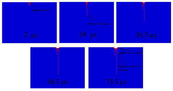
Figure 5.
Sequence diagram of crack growth in rock.
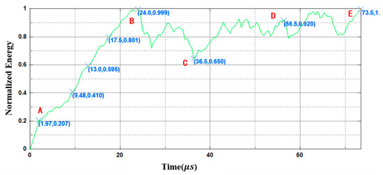
Figure 6.
Normalized energy curve of rock.
4.2. Effect of Jet Inclination on Microscopic Crack Propagation
The angle between the jet flow direction and the rock face’s normal direction is defined as the jet inclination angle α. The crack propagation at the same moment for different angles α for a jet velocity of 600 m/s is shown in Figure 7. According to the results in [20], the rock-breaking efficiency increases first, then decreases with an increase in the jet inclination angle. When the jet inclination angle is about 10°, the rock breaking effect is the best, so α is selected as 5°, 10°, 15°, 20°, 30°, and 40°. When water jets are used to impact crushed rock at the above angles, the macroscopic crater shape and microscopic crack propagation directions are significantly different.
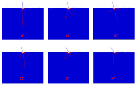
Figure 7.
Crack growth in rock impinged by jet at different angles.
Next, the water jets are analyzed at different angles for the impact rock crack propagation direction. Figure 7 demonstrates that when α is 5°, the impact rock does not present a large difference compared to the vertical impact rock center crack and radial crack. Nevertheless, the right lamellar crack in the left deflection 5° impact rock presents a more obvious propagation phenomenon. When the water jet impacted the rock with the rest of the above inclination, the central crack along the axial direction of the water jet and the radial cracks on both sides of the water jet presented a certain angle deflection based on the deflection angle of the water jet, and the central crack propagation direction was still in the axial direction of the water jet. The main reason for this result is as follows. When the water jet impinges on the rock, the high-density shear stress field formed near the impact point is larger than the maximum shear stress of the rock, and element failure is formed. The rock then releases compressive energy from the water jet axis position along the transverse direction, and the surrounding compressive stress σc gradually evolves into tensile stress σt, which causes the rock to bear tensile stress (as shown in Figure 8) when the tensile stress σt is greater than the tensile limit of the rock formed along the water jet axis direction of the tension type center crack.
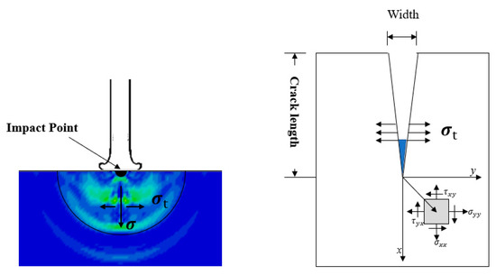
Figure 8.
Diagram of central crack formation.
To summarize, with a water jet inclination angle greater than 20°, the water jet impact on the rock cannot form stagnation pressure, making the internal energy utilization rate of the water jet transfer to the rock low. Additionally, the crack propagation becomes slow, and the erosion ability of the water jet on the rock is significantly reduced. However, in the range of 15° to 20°, the impact ability becomes stronger, lamellar crack propagation becomes obvious, and continuous impact of the water jet can easily produce rock chip flaking.
4.3. Crack Propagation Behavior under the Action of Confining Pressure
In underground engineering, the confining pressure dramatically influences rock crack sprouting, propagation, and fragmentation when subjected to impact loading. To study the influence of confining pressure on the length of crack emergence and the expansion of high-speed water jets impacting rock, the same velocity and different angles of high-speed water jets impacting rock under the action of confining pressure are used. Figure 9 shows the results of the crack propagation of the rock impacted by the jet at different angles under confining pressure. The comparison in Figure 9 shows that the confining pressure has an obvious inhibitory effect on crack propagation inside the rock, which not only inhibited crack propagation in the axial direction of the water jet, but also directed the lateral crack propagation mainly along the parallel direction of the rock surface. Additionally, the damage inside the rock was densely distributed around the crater, and there were no more obvious central cracks. When the confining pressure was 20 MPa, the confining pressure had a more apparent inhibiting effect on the crack propagation. The cracks, which were short and dense, were mainly densely distributed around the crater, and the crater depth and width presented a slight decrease compared to the confining pressure of 10 MPa. Hence, the confining pressure made the crack propagation trend decay, and the confining pressure and impact stress acted together to accelerate the rock unit damage around the crater.
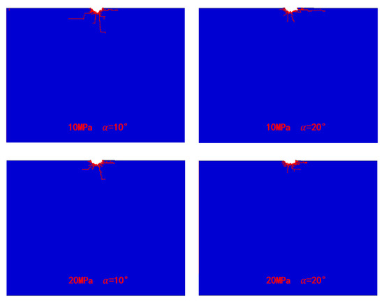
Figure 9.
Crack growth of the rock impinged by the jet at different angles under confining pressure.
Here, the number of elements damaged by the rock under jet action in the normal direction of the rock is shown in Table 3, with an increase in the confining pressure, the number of damaged elements first decreased and then increase. The results are consistent with the results in [21]. However, because the confining pressure on the central crack inhibition was more obvious rock damage was mainly distributed around the crater; the crater width showed a trend of changing first, followed by an increase, then decrease. By observing the crack propagation and change in crater size, we concluded that it is easier to promote rock cracking and crushing when the confining pressure is 10 MPa.
Table 3.
Damage of the rock element under confining pressure.
5. Experimental Verification
The rock specimen used in the experiment was a 10*10*10 cm natural granite square, and its various physical parameters are shown in Table 4. The same continuous water jet parameters as in Section 3.2 were used for the experiments, and the jet inclination angle α was selected as 5°, 10°, and 15°, respectively, to study the effect of the water jet on rock cracking under non-submerged conditions. The shape of the crater and the location of the impact point of the jet impacting the rock at different inclination angles are shown in Figure 10. Additionally, the crater was filled with silicone to facilitate observation of the specific shape of the crater. When the jet impact angle was 5°, the crater depth was not significantly different from the vertical jet impact, and the jet impact point was slightly away from the center of the crater. When the water jet impact angle was 15°or 20°, respectively, the internal lamellar cracks of the rock expanded in the opposite direction of the water jet inclination, resulting in macroscopic rock flaking in this direction. The specific shape of the crater is shown in Figure 11.
Table 4.
Test results for the physical parameters of granite.
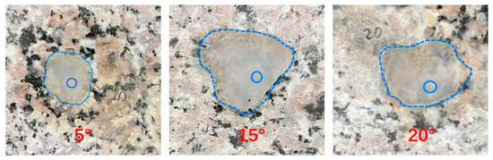
Figure 10.
Shape of the crater and jet impact point.
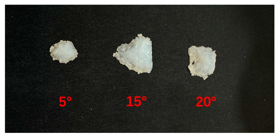
Figure 11.
Three-dimensional shape of the crushing crater.
6. Conclusions
This paper established a high-speed water jet impact rock breaking model using an SPH-FEM contact coupling algorithm that successfully reproduced the fragmentation process caused by crack proliferation under the impact load of a high-speed water jet. The main conclusions are as follows:
(1) The angle of incidence of the jet impacting the rock greatly influenced the propagation of the tension-type central axial crack inside the rock. The results of field experiments and numerical simulations showed that the angle of incidence of the jet determined the propagation direction of the tension-type central axial crack, and its propagation direction was always along the axial direction of the water jet. When the jet inclination was in the range of 15° to 20°, the tendency of lamellar crack propagation is evident, and the continuous impact of the jet was more likely to produce rock chip block spalling.
(2) When the rock was impacted by the jet at different angles under the confining pressure, the direction of crack propagation deviated from the direction without the confining pressure and gradually became parallel to the rock plane. Confining pressure promoted unilateral crack propagation in the direction of the water jet impact, making the rock more likely to produce unilateral rock chip spalling.
Author Contributions
Y.P. conceived and designed the research; S.Z. performed the experiment and wrote the manuscript; X.M. was responsible for review and data collation; K.P. did experimental verification; F.H. edited the manuscript. All authors have read and agreed to the published version of the manuscript.
Funding
This research was supported by the Natural Science Foundation of Hebei Province Ecological Intelligent Mine Joint Fund (E2022402102). This support is greatly acknowledged and appreciated.
Data Availability Statement
The datasets generated and analyzed during the current study are available from the corresponding author upon reasonable request.
Acknowledgments
Z.Y. and Y.H. are acknowledged for their valuable technical support.
Conflicts of Interest
The authors declare no conflict of interest.
References
- Chen, Z.S.; Huang, L.Y.; Du, B.X. Insight of hydrodynamic characteristics related to ultra-high pressure water jet rust removal sprayers. Explos. Shock Waves 2022, 42, 158–171. [Google Scholar] [CrossRef]
- Wang, Y.F.; He, X.Q.; Wang, E.Y. Research progress and development tendency of the hydraulic technology for increasing the permeability of coal seams. J. China Coal Soc. 2014, 39, 1945–1955. [Google Scholar] [CrossRef]
- Tripathi, R.; Hloch, S.; Chattopadhyaya, S. Application of the pulsating and continuous water jet for granite erosion. Int. J. Rock Mech. Min. Sci. 2020, 126, 104209. [Google Scholar] [CrossRef]
- Mi, J.Y.; Huang, F.; Li, S.Q. Numerical simulation of rock breaking by rear-mixed abrasive water jet based on an SPH-FEM coupling algorithm. J. Vib. Shock 2021, 40, 132–139. [Google Scholar] [CrossRef]
- Jiang, H.X.; Du, C.L.; Liu, S.Y. Numerical Simulation of Rock Fragmentation under the Impact Load of Water Jet. Shock Vib. 2014, 32, 1–11. [Google Scholar] [CrossRef]
- Yu, R.; Dong, X.; Li, Z. SPH-FEM simulation of concrete breaking process due to impact of high-speed water jet. AIP Adv. 2021, 11, 45–52. [Google Scholar] [CrossRef]
- Li, G.S.; Liao, H.L.; Huang, Z.W. Rock damage mechanisms under ultra-high pressure water jet impact. J. Mech. Eng. 2009, 45, 284–293. [Google Scholar] [CrossRef]
- Wu, Z.; Yu, F.; Zhang, P. Micro-mechanism study on rock breaking behavior under water jet impact using coupled SPH-FEM/DEM method with Voronoi grains. Eng. Anal. Bound. Elem. 2019, 108, 472–483. [Google Scholar] [CrossRef]
- Oh, T.M.; Prasidhi, A.K.; Cho, G.C. Effect of water jet geometric parameters on rock fracturing. KSCE J. Civ. Eng. 2014, 18, 772–779. [Google Scholar] [CrossRef]
- Sheng, M.; Tian, S.C.; Li, G.S. Shale rock fragmentation behaviors and their mechanics by high pressure waterjet impinging (in Chinese). Sci. Sin.-Phys. Mech. Astron. 2017, 47, 99–106. [Google Scholar] [CrossRef]
- Xue, Y.; Si, H.; Chen, G. The fragmentation mechanism of coal impacted by water jets and abrasive jets. Powder Technol. 2020, 361, 849–859. [Google Scholar] [CrossRef]
- Xue, Y.; Si, H.; Hu, Q. The propagation of stress waves in rock impacted by a pulsed water jet. Powder Technol. 2017, 320, 179–190. [Google Scholar] [CrossRef]
- Attaway, S.W.; Heinstein, M.W.; Swegle, J.W. Coupling of smooth particle hydrodynamics with the finite element method. Nucl. Eng. Des. 1994, 150, 199–205. [Google Scholar] [CrossRef]
- Zhao, J.; Zhang, G.C.; Xu, Y.J. Numerical simulation and experimental study on rock breaking by particle jet based on SPH method. Explos. Shock Waves 2017, 37, 479–486. [Google Scholar] [CrossRef]
- Price, D. Smoothed Particle Hydrodynamics. World Sci. 2005. [Google Scholar] [CrossRef]
- Hong, Q. New Method and Application of Smooth Particle Fluid Dynamics; Science Press: Beijing, China, 2017; Volume 6, p. 114. [Google Scholar]
- Vignjevic, R.; Vuyst, T.D.; Campbell, J.C.A. Frictionless Contact Algorithm for Meshless Methods. Comput. Model. Eng. Sci. 2006, 13, 117–128. [Google Scholar]
- Wang, J.; Yin, Y.; Luo, C. Johnson–Holmquist-II (JH-2) constitutive model for rock materials: Parameter determination and application in tunnel smooth blasting. Appl. Sci. 2018, 8, 1675. [Google Scholar] [CrossRef]
- Ren, F.; Fang, T.; Cheng, X. Study on rock damage and failure depth under particle water-jet coupling impact. Int. J. Impact Eng. 2020, 139, 103504. [Google Scholar] [CrossRef]
- Liu, X.; Liu, S.; Ji, H. Numerical research on rock breaking performance of water jet based on SPH. Powder Technol. 2015, 286, 181–192. [Google Scholar] [CrossRef]
- Li, H.; Liu, S.; Jia, J. Numerical simulation of rock-breaking under the impact load of self-excited oscillating pulsed water jet. Tunn. Undergr. Space Technol. 2020, 96, 103179. [Google Scholar] [CrossRef]
Disclaimer/Publisher’s Note: The statements, opinions and data contained in all publications are solely those of the individual author(s) and contributor(s) and not of MDPI and/or the editor(s). MDPI and/or the editor(s) disclaim responsibility for any injury to people or property resulting from any ideas, methods, instructions or products referred to in the content. |
© 2022 by the authors. Licensee MDPI, Basel, Switzerland. This article is an open access article distributed under the terms and conditions of the Creative Commons Attribution (CC BY) license (https://creativecommons.org/licenses/by/4.0/).