Abstract
The paper studies a new distributed control method to solve the economic dispatch problem (EDP) under directed topology based on consensus protocol. Electrical equipment is closely related to frequency, and the frequency of each generator varies independently during operation. Therefore, it hinders the realization of economic dispatch. To solve the problem, we combine a frequency regulator with a consensus protocol, which eliminates the effect of frequency variation on the designed consensus algorithm. Meanwhile, considering the problem of excessive communication cost and low computational efficiency in large-scale power systems, an event-triggered mechanism is introduced into the designed algorithm. Furthermore, in order to overcome the unexpected loss of communication links, the time-varying topology mechanism is employed to develop the distributed economic dispatch (DED) algorithm to improve the robustness. Then, the stability of the above algorithm is proved by graph theory and convergence analysis. Finally, several simulations illustrate that our proposed methods are effective.
1. Introduction
With the emergence of the smart grid, people’s power consumption has become more scientific and low consumption. How to solve the problem of power generation in power systems at low cost is an important topic of general concern in society. EDP is a conditional optimization problem, which mainly studies some dispatch methods to ensure reliable power supplies to users with the lowest generation cost [1]. At present, the economic dispatch methods of a smart grid are mainly divided into the centralized method and distributed method. The traditional centralized method requires a central processing unit to capture global resources for all generators and calculate large amounts of data [2,3], such as the Lagrange multiplier method and neural network Approach [4,5]. However, with the continuous expansion of power system scale, it leads to the over dispersion of power systems. In view of this situation, the centralized method has limitations so that the communication cost increases and the processing capacity decreases. Hence, a distributed algorithm is very suitable to solve EDP in the distributed power system [6], which does not need a centralized control center, and each generator only needs to obtain local information of adjacent generators to complete EDP.
In recent years, many DED methods have emerged. Generally distributed algorithms are designed based on consensus protocol [7]. Meanwhile, the solution of these methods should also meet supply and demand balance constraints. At the beginning of the study, the DED method has some limitations. For instance, a consensus-based EDP algorithm for the microgrid is proposed in [8], which obtains the optimal solution by obtaining the global power mismatch value in advance. However, the global power mismatch value still needs a control center to calculate, so the algorithm is not completely distributed. In [9], an innovation term is introduced on the basis of the consensus term, which is used to make an incremental cost converge to a common value and ensure balance between supply and demand. Although [9] is a fully distributed algorithm, its scope of application is still limited. At present, considering the diversity of the communication environment, some DED algorithms had been proposed. In terms of communication topology, the algorithm mentioned in [10] makes up for the shortcoming of the traditional consensus-based algorithm that only after convergence can there be feasible solutions, and it is applicable for the jointly connected switching undirected topology. Close to reality, [11] combines the frequency control method and consensus protocol under undirected topology, which is introduced to balance the actual power between load and power generation in the process of economic dispatch. However, the above methods are carried out in the ideal communication and do not take into account the problem of communication asynchrony. Hence, [12] proposes a DED algorithm to overcome the difficulties of of asynchronous communication under unbalance directed topology. The algorithm needs only the row-stochastic weighted matrices, which assigns the weight of messages that each generator receives from its in-neighbors. The algorithm in [13] has higher convergence speed than the previous method. It presents an algorithm of distributed Lagrangian momentum, which uses two momentum terms to track the gradient and updates the Lagrange multipliers in non-uniform steps. Furthermore, since all of the above methods are real-time communication, it can consume more communication resources and have low computational efficiency when these methods are applied to a large-scale power system. Therefore, the event-triggered mechanisms are added into some algorithms [14,15,16]. The theta-logarithmic barrier-based method and consensus-based approach are proposed in [14], which introduce the event-triggered mechanism. To improve economic dispatch efficiency, a novel event-triggered distributed accelerated primal-dual algorithm with uncoordinated step sizes is proposed [16]. In addition, uncertain communication link failure may lead to continuous changes in the topology of the communication network. Therefore, introducing the time-varying topology mechanism into the algorithm can eliminate the adverse effects of topology changes. Ref. [17] introduces the dual gradient idea into the consensus algorithm and designs a DED algorithm under time-varying topology, which uses a fixed step size and column random mixing matrix to accurately guide the incremental cost of all generators to reach the optimal consensus value. Ref. [18] proposes the gradient push-sum method in time-varying topology, which ensures the robustness of the system and improves the convergence efficiency. In general, these algorithms are updated iteratively in a relatively ideal environment, but in the actual situation, many practical factors should be considered in the process of economic dispatch. Recently, some DED methods considering complex environments have emerged, such as transmission loss [19,20,21,22,23], time delay [24,25,26,27,28], cyber-attack [29,30], privacy protection [31], and so on.These methods greatly improve the adaptability of EDP in a complex environment. In addition, the economic dispatch problem of a smart grid can be extended to energy dispatching. For example, in [32], a day-ahead optimal dispatching method for a smart grid is proposed with the objective of minimizing the fuel energy input from the main grid. It is mentioned in [33] that increasing the share of renewable energy connected to the grid frequency converter can reduce the inertia of the power system, which is critical to the stability of the grid frequency. Therefore, we can take such factors into account in the algorithm. Ref. [34] proposed a fully distributed hierarchical control framework for an autonomous AC microgrid, which only requires local inter-agent interaction with a sparse communication network. Therefore, it is completely distributed.Finally, some articles on multi-intelligent systems are also helpful to the optimization of our economic scheduling algorithm [35,36].
Combined with the actual operating environment, the frequency will have a certain impact on the normal operation of the generator. However, some studies in the literature consider the change of frequency. Most algorithms add a frequency control term to the consensus protocol to balance the actual power of the generation and load [11]. This is a novel innovation, but it still has some aspects that are not considered enough. Inspired by the distributed algorithm in [11], in this paper, an event-triggered DED controlled algorithm with a frequency regulator under time-varying topology is proposed. The main innovations and improvements are summarized below: (1) Compared with [11], Ref. [11] considers that the frequency of each generator is always the same. However, in practice, the frequency of each generator may be different due to the uncertainty of frequency variation. Therefore, we introduce a frequency regulator into the consensus protocol to eliminate the impact of frequency change on the economic dispatching process, which is more suitable for the power generation process in the actual scenario, and ensure the balance of power supply and demand. (2) The existing work based on undirected topology [10,11,14,15] does not consider the case of communication disturbance or asynchronous communication; i.e., there is one-way communication between two generators. So, we use a row-stochastic and column-stochastic matrix to design an algorithm under directed topology to solve these problems. So, our algorithm has the characteristics of one-way communication. (3) The paper adds an event-triggered mechanism to the algorithm, which makes up for the disadvantages of consuming too many communication resources and low computing efficiency in a large-scale power system. Therefore, the communication frequency of our algorithm is greatly reduced. (4) The communication fault proposed in [11] refers to the situation in which a generator cannot measure the frequency, but it does not consider the change of the actual topology caused by the communication fault. We consider that the topology may change at every moment due to line fault in this paper. Therefore, a new time-varying topology mechanism is added into the algorithm to increase the robustness of the entire power system, which makes the algorithm we designed more practical. Different from the design in [17,18], we design a mapping topology function in the consensus algorithm to indicate the topology at any time.
The structure of this paper is divided several parts: we describe some preliminaries in Section 2. Section 3 give a DED formulation and consensus protocol related to economic dispatch. Several DED control methods are proposed in Section 4 to solve EDP. In Section 5, we prove the convergence of the design algorithm through theoretical analysis. Several simulations are carried out in Section 6. Finally, a brief conslusion is provided in Section 7.
2. Preliminary
This section describes the correlation graph theory used in the paper, which is necessary to describe the communication network. In a smart grid, a directed topology denotes the relationship between multiple generators, which is composed of node set and edge set . A directed edge from to is represented as . To simplify the notation, it is assumed that there is no self-loop at any node, i.e., . The in-neighbor and out-neighbor of each node are represented as and , respectively. and denote the out-degree and in-degree of each node, respectively. G is strongly connected if for each pair of , there are paths from to and from to .
The Laplacian matrix of a digraph is elucidated as . is a diagonal matrix, where denotes the diagonal element, . indicates an dimensional adjacency matrix. A is a row-stochastic matrix if it satisfies for . A is a column-stochastic matrix if it satisfies for . The paper introduces a row-stochastic matrix and a column-stochastic matrix ; the elements of the matrix are defined as:
Considering the time-varying topology, the communication topology changes with each iteration. Suppose the set of all possible topologies is . Function , . Therefore, we redefine and . represents the edge set of the topology at the iteration. is the adjacency matrix in the k iteration corresponding to the current topology. The joint graph of is defined as . is said to be uniformly jointly strongly connected if there exists a constant such that is strongly connected for any [18]. The in-neighbor and out-neighbor of each node at the k-th iteration are represented as and , respectively. Then, the Laplacian matrix where ,.
3. Problem Formulation and Consensus Approach
3.1. Formulation of the EDP
EDP aims to minimize generating electricity i‘s total cost by rationalizing the power of generators. Therefore, EDP is a optimization problem with a constraint condition, so that minimizes the following objective function,
where represents the output power of the generator. . is the cost function. and represent the total cost and total power demand in the power system, respectively. and are defined as the minimum output power and the maximum output power of the generator. (2) guarantees the balance of power supply and demand during the operation of the entire power system. By limiting the output of each generator by (3), we can ensure the normal operation of each generator. In most cases, is generally a quadratic convex function, which is generally defined as
where , and denote the coefficients of each generator’s cost function, respectively. To facilitate problem analysis, the following assumptions are provided.
Assumption 1.
The communication topology in this paper is a directed connected graph. The corresponding adjacency matrix is row-stochastic matrix and column-stochastic matrix , which satisfy ,.
Assumption 2.
For generators with frequency regulators, the frequency of all generators can be monitored and initially run at a rated frequency . The frequency of each generator can be different and vary periodically within the normal range.
3.2. Centralized Lagrangian Method
In order to solve EDP, the traditional centralized methods mainly rely on some global information in the power system and even require the parameter information of each generator. At present, the Lagrange multiplier method is the main centralized EDP method. Then, the Lagrangian function is defined as follows:
where is both incremental cost and Lagrange multiplier. Therefore, is the optimal incremental cost, which can be obtained by the Lagrange multiplier method.
According to (6) and (7), the optimal incremental cost can be calculated by Equation (8).
Considering the constraints (2) and (3), the solution of (1) can be calculated through (6).
where denotes the optimal output power for the generator at the iteration. The solution of (1) can be expressed as .
Remark 1.
The centralized economic dispatch method requires some global resources of the entire power system and some detailed parameters of each generator. However, if there are too many generators in the power system, the method is not feasible. Hence, we introduce a basic distributed consensus protocol to solve distributed EDP.
3.3. Distributed Consensus Protocol
The necessary condition to realize economic dispatch in a power system is that each incremental cost has the same value. For the sake of overcoming the shortcomings of the centralized approach, a discrete-time DED consensus protocol under undirected topology is proposed as follows [11]. However, due to the different ability of each generator to obtain the state information of neighbor nodes, the bidirectional communication between distributed generator units may not be realized. Therefore, we will consider the DED under directed communication.
where denotes the incremental cost of the generator at the iteration. is a fixed step size. represents the weight coefficient from generator j to generator i. Let , and (10) can be rewritten as
where is a Laplacian matrix. Using (11), it is more convenient for us to deduce the convergence of the algorithm.
Lemma 1.
([11]) (11) can converge to the following as:
if and only if the communication topology is connected and satisfies
where is the initial incremental cost of generator i. . is the largest absolute value of the eigenvalue of .
4. Algorithm Design and Description
4.1. DED Approach with Frequency Regulator
Based on (10), we propose a DED algorithm with a frequency regulator. Different from the algorithm proposed in [11], the frequency of each generator can be different and fluctuate periodically within the normal range. We add the frequency factor to the consensus protocol by introducing the objective attraction function [18] as follows
where denotes a tatget attraction function, which helps achieve consensus. In the power system, if all reach consensus under the action of consensus protocol, then . So, we plug it into (14)
From (15), we can obtain . Therefore, denotes the error between the optimal value and the current value. Furthermore, we can derive that when economic dispatch is complete. Therefore, our goal is to design a target attraction function so that our algorithm can reach consensus. Next, we designed a DED algorithm with a frequency regulator to achieve the goal.
where is not only a frequency regulator but also a local frequency error. The frequency regulator can eliminate the effect of each generator frequency deviation because quickly approaches zero under the action of the algorithm. and are the learning rates. is a proportional gain coefficient. N is the number of generators. The real-time discrete frequency of each generator is defined as . changes periodically and stays the same for every period. From algorithm (16)–(18), can be calculated for each generator in each iteration. Then, is obtained by (9). After a finite number of iterations, converges to the same value. At the same time, the active power of each generator reaches the optimal value , and the total generation cost is also the minimum; that is, economic dispatch is completed. The algorithm mentioned is summarized in Algorithm 1.
| Algorithm 1 DED algorithm with frequency regulator |
|
4.2. Event-Triggered-Based DED Approach
With the increasing scale of the power system, the amount of resources for interaction between generators has increased dramatically, resulting in low computational efficiency, which may lead to communication congestion and even economic dispatch failure. To solve this problem, we introduce an event-triggered mechanism based on Algorithm 1.
In order to conveniently describe the event-triggered algorithm, a necessary introduction is given first. Event-triggered control means that information transmission is only allowed between generators after triggering conditions are satisfied, which effectively reduces the amount of computation, reduces the waste of communication bandwidth and improves the efficiency of economic dispatch. The notation specification is defined as follows: for , denotes the variable transmitted by the node in the communication topology at the iteration. denotes the transmission variable of the node at event-triggered time instant . is the number of events triggered at the current time instant for the node. denotes the event-triggered function. Then, we define the event-triggered condition as
where node i can receive and send to the () neighbor node in the next iteration if (19) is satisfied. The event-triggered discrete instants for node i is defined iteratively as , which represents the new event-triggered instant when the event-triggered condition is met. Moreover, the discrete time method naturally excludes zeno behavior [15].
Consider that the event-triggered mechanism is suitable for large power systems, we introduce leader–follower mode into the algorithm in order to avoid communication failures as much as possible. In this mode, leaders with a frequency regulator can measure the frequency, and followers without a frequency regulator have no frequency measurement ability. Therefore, we introduce a new event-triggered-based DED approach.
Follower:
Leader:
where represents the set of neighbor leader generators adjacent to leader generator i. denotes the gain coefficient. is an auxiliary variable. is the difference of active power between two iterations. is a row-stochastic matrix and is a column-stochastic matrix. Event-triggered condition:
where , , . , . . If and only if and , the event will be triggered.
Remark 2.
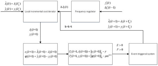
It can be seen from (20)–(27) that the leader generator can only receive messages from the neighbor leader and can send messages to any neighbor generator it points to. Meanwhile, the follower can communicate with any neighbor generator. Then, under the action of the consensus term, each generator i‘s incremental cost can be the same. The algorithm mentioned is summarized in Algorithm 2. Figure 1 shows the flow of Algorithm 2.

Figure 1.
Algorithm flow chart.
| Algorithm 2 Event-triggered based DED approach (Leader–Follower) |
|
4.3. Robustness to Time-Varying Topology
At present, most related work generally considers that the communication topology is unchanged. However, in practical applications, the communication link may have uncertain faults, which may lead to changes of communication topology. Therefore, for the sake of solving the problem of imperfect communication, we design a robust DED consensus algorithm for time-varying topology based on the above algorithm, which is very necessary for the future smart power grid. Since the topology is time-varying, is the set of all possible topologies. The mapping topology function is expressed as , which represents the topology of the iteration and its corresponding adjacency matrixes are and .
Assumption 3
([18]). The time-varying directed topology is uniformly jointly strongly connected, i.e., is strongly connected for any with some constant .
Assumption 4.
In the case of time-varying topology, and can be guaranteed for any and . Communication between leaders is always smooth.
The time-varying based event-triggered economic dispatch approach is as follows.
Follower:
Leader:
where the event-triggered condition remains unchanged and the communication topology of each iteration may change. .
5. Convergence Analysis
In this part, the convergence of the proposed algorithm is analyzed. First, the convergence of and is proved under an event-triggered condition. Second, it is proved that the protocol can converge even considering the time-varying topology. To give the convergence analysis, we need the following lemmas.
Lemma 2
([37]). If the graph is connected, its Laplacian matrix is and the spectral radius satisfies , then
Lemma 3.
is the entire n-order matrix, let , be the spectral radius, then
Theorem 1.
In a directed connected graph, let . As , then can converge by adjusting so that .
Proof.
We can observe that is a geometric sequence. Therefore, we can use the geometric sequence summation formula to calculate.
So as and , then . We can conclude that
then (37) converges to . □
5.1. Convergence under Event-Triggered Conditions
Proof.
According to (21), . Let and . So, (21) can be converted to the following form.
From , we can derive that , where
,. Then, (39) can be written as
According to Assumption 1 and Lemma 3, . The dynamics of the power system and event-triggered constraints, trigger error and local power error cannot be arbitrarily large. Therefore, we suppose and have upper bounds and for some norms, i.e., . Assuming and in each iteration, under such extreme conditions, if we can prove that the proposed algorithm can converge, then the algorithm must always converge in general [11]. Let ; then, it can be deduced
To prove the convergence of (41), we must find a matrix norm to satisfy geometric series converges [7]. According to Assumption 1, , then the convergence condition of is satisfied. Therefore, (41) coverges to
where . The convergence of can be proved by using the same method, so it is omitted here. By analyzing (40)–(42), can be proved to converge. Next, we analyze the convergence of . Since converges, we just need to prove that (43) converges.
By Lemma 2, converges to . Let , where is the average vector of . Then,
Since there are event-triggered constraints, each entry of can not be arbitrarily large. So, we suppose the entries of have the same upper bound . Then, is an upper bound of for some norms, i.e., . It means that the algorithm can converge if the proposed algorithm can still converge when . So, when , let , it can be deduced
According to Theorem 1, we can prove that converges. Therefore, it can be concluded that (47) converges [7]. Furthermore, since is a Laplacian matrix, then (47) converges to 0. We can obtain . So, (46) converges to 0. Next, let and , then
According to Lemma 2, it converges to .
Let ; then, the convergence of (48) is proved by inductive reasoning.
- when , .
- when , suppose converges.
- when ,
Considering the actual power system, the frequency variation cannot be arbitrarily large. It assumes that is an upper bound of for some norms, i.e., . According to the above similar ideas, we just need to make sure so that converges, where . Then, we can obtain that converges so that (49) converges to 0 because guarantees that each entry of it is the same. Therefore, we can deduce that (48) converges to . By deducing that (46) and (48) converge, it can be concluded that each vector of converges to the same value; that is, each incremental cost reaches consensus. □
5.2. Convergence in Time-Varying Topology
Considering the time-varying topology, according to (23), . Then, (23) can take the following form.
Next, we need to prove that converges. As mentioned above, there exists an that makes . Under such extreme conditions, if we can prove that the proposed algorithm can converge, then the algorithm must always converge in general. Therefore, we need to prove that converges.
Suppose
where . Set and , respectively, .
According to Assumption 4, we can obtain and . Using Lemma 3, and are proved to be convergent. Since (51) can reach convergence under extreme conditions, then (51) must be convergent. Therefore, converges so that converges. Similarly, can also be proved to be convergent, which is omitted here. To sum up, (50) is proved to converge.
According to Assumption 4, communication between leaders is always smooth; then, the connection between leader generators will not be interrupted in the process of time-varying topology. Therefore, the influence of topology change on the frequency regulator is negligible, which is equivalent to converging to 0 under a fixed topology. Combined with relevant conclusions of (48), we can ignore the value of the frequency regulator in the process of proving the convergence of (30). Let ,. Since (50) converges, then (30) take the following form.
where . The entries of have the same upper bound, and every entry of is the same. So, values have upper bounds for some norms, i.e., . When , let and , respectively. We can obtain , so . Therefore, (54) becomes
The convergence of (55) is proved by mathematical induction.
.
converges.
.
We deduced that converges. Therefore, (55) converges so that it is deduced that (54) converges. It has been shown above that (54) converges, but consensus is not guaranteed. Next, we analyze the consensus of (54) on the basis of (55).
where . Set and , respectively, . According to Assumption 5 and (56), we know that and . Thus, we can deduce the consensus of (54) under extreme conditions as follows. Using Lemma 2, (55) becomes
It can be inferred from (57) that (55) can reach consensus under extreme conditions. Therefore, (54) or (55) can always reach consensus.
6. Simulation and Analysis
In this part, we conduct some simulations to verify the effectiveness of our algorithm. Frequency is variable in an electric power system, so we assume that the frequency changes periodically. According to the number of generators, we can divide them into four-generator systems and 10-generator systems. For a four-generator system, we study the economic dispatch algorithm with a frequency regulator under the circumstances of an event-triggered mechanism and the directed graph topology. Extending to 10-generator systems, we simulate economic dispatch algorithms with event-triggered mechanism under time-varying topology in leader–follower mode. Finally, the PI algorithm in [11] is compared with the algorithm we design to verify the superiority of our designed algorithm. Our parameters in the above algorithm are set as follows:, , , , , , .
6.1. Four-Generator System
We simulate a four-generator system, and Figure 2 shows the corresponding directed topology. The cost function coefficients and power limit for each generator in the system are listed in Table 1. Next, simulation experiments will be carried out. In this case, we add an event-triggered mechanism to the algorithm and we set the total power demand of the entire power system as 599 kw. Figure 3 and Figure 4 illustrates the simulation results. From Figure 3a, we can see that the output of each generator remains stable whenever reaches consensus. is affected by the active power constraint and adopts the minimum power generation. The results in Figure 3b show the total cost of power generation in each iteration, and the total cost varies with the changing output power. Next, the frequency variation process for each generator is shown in Figure 3c, and the frequency varies within the normal range. Figure 3d shows the working process of each generator frequency regulator, and we can see that it goes to zero for a very short time after each change in frequency. Thus, the frequency regulator eliminates the influence of the frequency changes. Using the event-triggered mechanism’s advantages, the iterative process of incremental cost for each generator is shown in Figure 4a. The incremental cost varies with frequency, and each generator transmits new information to its neighbor generators in the next iteration only if the event-triggered condition is met. Finally, the algorithm can achieve consensus. The iterative process of auxiliary variable is shown in Figure 4b, and we can see that also converges under the change in frequency. Figure 4c shows the event-triggered instant of each generator, i.e., Moreover, the event-triggered statistics during iteration are listed in Table 2. We can see from Table 2 that the event-triggered mechanism improves the efficiency of calculation. Figure 4d shows the relationship between the power generation and total demand. It can be seen that the balance of supply and demand is achieved within the allowable range of error.
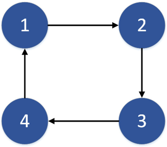
Figure 2.
Four-generator system communication topology.

Table 1.
Generator cost function coefficient.
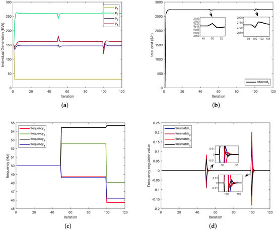
Figure 3.
(a) The output power of each generator. (b) The total cost of power generation. (c) The frequency variation process. (d) The process of frequency regulator.
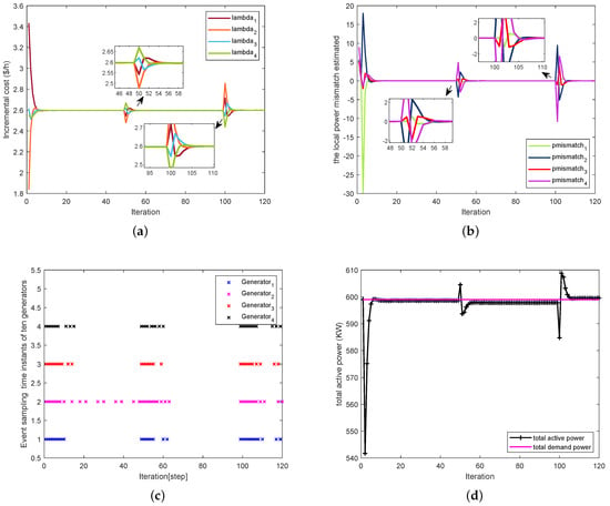
Figure 4.
(a) The iteration of incremental cost . (b) The iterative process of auxiliary variable . (c) Event sampling instants of four generators. (d) Total active power.

Table 2.
Generator event-triggered statistics.
6.2. Ten-Generator System
In this part, we simulate a ten-generator system . From Figure 5a, we obtain the corresponding directed topology G. The blue nodes are the leaders and the green nodes are the followers. The dotted line indicates the communication between leaders and the solid line indicates the communication between any two nodes.

Figure 5.
(a) Topology G. (b) Topology . (c) Topology .
In order to improve the robustness of topology, we add a time-varying topology mechanism to the event-triggered algorithm. In this case, the 10-generator system uses leader–follower mode, and only the leader–generator has a frequency regulator. From Figure 5b,c, all possible topology sets are set to , and the time-varying topology switches between two fixed topologies and at each iteration. and represent the edge set of and , respectively. , which represents the topology of the iteration. Its corresponding adjacency matrixs are and . is defined as follows.
In addition, we need to ensure that is uniformly jointly strongly connected. Then, we set the total power demand of the entire power system as 4085 KW. The cost function coefficients and power limit for each generator in the system are listed in Table 3. We can obtain the simulation results from Figure 6 and Figure 7. Figure 6 is similar to the explanation of Figure 3; it shows the variable iteration in frequency variation. Figure 7a shows that our algorithm still achieves consensus under the time-varying topology and event-triggered mechanism. Figure 7b shows that the auxiliary variable can still converge to a range in a time-varying topology. The information in Figure 7c about the event-triggered mechanism is summarized in Table 4. Figure 7d shows that the algorithm still balances supply and demand in the allowable range of error, reflecting the robustness of the algorithm.

Table 3.
Generator cost function coefficient.
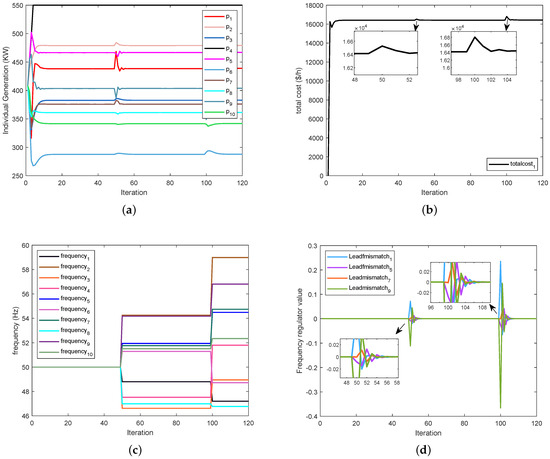
Figure 6.
(a) The output power of each generator . (b) The total cost of power generatio. (c) The frequency variation process . (d) The process of frequency regulator.

Table 4.
Generator event-triggered statistics.
6.3. Comparison Experiment
The purpose of this paper is to confirm the validity, correctness and superiority of our designed algorithm; we compare it with the PI algorithm mentioned in [11] from the perspective of event-triggered times, convergence speed and total power generation cost.
After introducing the event-triggered mechanism, from Figure 8a,b and Table 5, we can obtain that the number of iterations in this algorithm is significantly reduced, which reduces the consumption of communication resources compared with the PI algorithm. It can be observed from Figure 8c,d that the PI algorithm promotes the incremental cost to achieve consensus in 18 iterations, while the event-triggered algorithm only needs 12 iterations to achieve consensus. Therefore, the convergence speed of the event-triggered algorithm is higher than that of the PI algorithm. Figure 9 shows that the total power generation cost of the PI algorithm and event-triggered algorithm is almost the same. Under the same total power generation cost, according to the above analysis, the event-triggered algorithm we designed is obviously better than the PI algorithm.
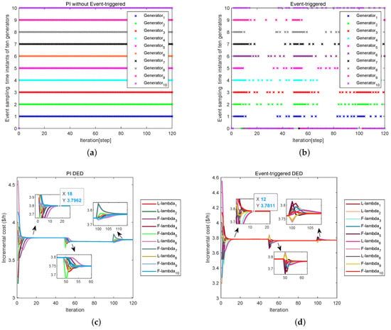
Figure 8.
(a) PI without event-triggered. (b) Event-triggered. (c) PI DED. (d) Event-triggered DED.

Table 5.
Comparison of iteration times between two algorithms.
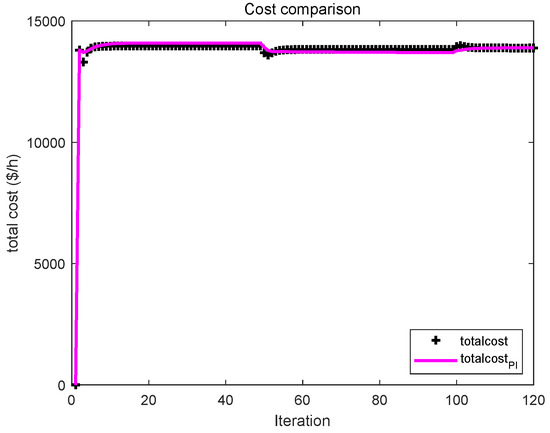
Figure 9.
Comparison of total cost of two algorithms.
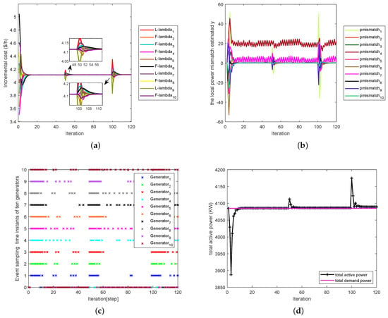
Figure 7.
(a) The iteration of incremental cost . (b) The iterative process of auxiliary variable . (c) Event sampling instants of four generators. (d) Total active power.
7. Conclusions
In this paper, a novel DED control method is proposed to solve EDP under directed topology based on consensus protocol, which is suitable for a more general environment. The method introduces a frequency regulator into the consensus protocol to eliminate the influence of the frequency difference change of each generator. Moreover, considering large-scale power systems, we added an event-triggered mechanism to the method to decrease the communication resources. This method only needs to update the current state after meeting the triggered conditions, so it improves the efficiency of our calculation. In addition, the robustness of the algorithm is improved by introducing a time-varying topology mechanism. The mechanism uses the mapping topology function to carry out economic dispatch under the topology at any time. Finally, numerical experiments verify the validity of the method. Nevertheless, the method is not perfect. It is worth emphasizing that the algorithm in this paper also has limitations. For example, our frequency changes periodically. The frequency change period simulated in the experiment is 50 s. In addition, we need to meet a condition when we introduce the time-varying topology mechanism; that is, the topology we design must be a joint uniformly connected graph to meet the convergence of the algorithm. Thus, future works will focus on network attack, transmission losses, ramp rate limits for power generators and other practical operational constraints.
Author Contributions
Conceptualization, W.M.; software, W.M.; formal analysis, W.M. and L.J.; investigation, W.M., L.J. and S.Y.; resources, W.M. and L.J.; writing—original draft preparation, W.M.; writing—review and editing, W.M. and L.J.; supervision, L.J. and H.L.; funding acquisition, L.J. All authors have read and agreed to the published version of the manuscript.
Funding
This research was funded by the National Natural Science Foundation of China under Grant Nos. 61876200 and 62006031 and in part by the Major Scientific and Technological Research Program of Chongqing Municipal Education Commission under grant No. KJZD-M202100602.
Institutional Review Board Statement
Not applicable.
Informed Consent Statement
Not applicable.
Data Availability Statement
Not applicable.
Acknowledgments
This research was funded by the National Natural Science Foundation of China and in part by the Major Scientific and Technological Research Program of Chongqing Municipal Education Commission.
Conflicts of Interest
The authors declare no conflict of interest.
Abbreviations
The following abbreviations are used in this manuscript:
| Abbreviations | |
| EDP | Economic Dispatch Problem |
| DED | Distributed Economic Dispatch |
| Nomenclature | |
| symbolic variable | describe |
| the output power of the generator. | |
| total cost. | |
| total power demand. | |
| the minimum output power of the generator. | |
| the maximum output power of the generator. | |
| the incremental cost of the generator at the iteration. | |
| a fixed step size. | |
| the weight coefficient from generator j to generator i. | |
| a Laplacian matrix. | |
| a target attraction function. | |
| not only a frequency regulator but also a local frequency error. | |
| the real-time discrete frequency of each generator. | |
| the variable transmitted by the node in the communication topology. | |
| the transmission variable of the node at event-triggered time instant | |
| the number of event-triggered. |
References
- Wen, G.; Yu, X.; Liu, Z. Recent progress on the study of distributed economic dispatch in smart grid: An overview. Front. Inf. Technol. Electron. Eng. 2021, 22, 25–39. [Google Scholar] [CrossRef]
- Chowdhury, B.H.; Rahman, S. A review of recent advances in economic dispatch. IEEE Trans. Power Syst. 1990, 5, 1248–1259. [Google Scholar] [CrossRef]
- Bermdez, J.F.; Alvarez, M. Inclusion of ancillary services in a cost-based centralized economic dispatch solution for hydrothermal systems. In Proceedings of the 2007 Large Engineering Systems Conference on Power Engineering, Montreal, QC, Canada, 10–12 October 2007; pp. 131–136. [Google Scholar]
- Mohatram, M. Hybridization of artificial neural network and lagrange multiplier method to solve economic load dispatch problem. In Proceedings of the 2017 International Conference on Infocom Technologies and Unmanned Systems (Trends and Future Directions) (ICTUS), Dubai, United Arab Emirates, 18–20 December 2017; pp. 514–520. [Google Scholar] [CrossRef]
- Mohammadi, A.; Varahram, M.H.; Kheirizad, I. Online solving of economic dispatch problem using neural network approach and comparing it with classical method. In Proceedings of the 2006 International Conference on Emerging Technologies, Peshawar, Pakistan, 13–14 November 2006; pp. 581–586. [Google Scholar] [CrossRef]
- Espina, E.; Llanos, J.; Burgos-Mellado, C.; Cárdenas-Dobson, R.; Martínez-Gómez, M.; Sáez, D. control strategies for microgrids: An overview. IEEE Access 2020, 8, 193412–193448. [Google Scholar] [CrossRef]
- Mesbahi, M.; Egerstedt, M. Graph Theoretic Methods in Multiagent Networks; Princeton University Press: Princeton, NJ, USA, 2010. [Google Scholar]
- Xu, Y.; Li, Z. Distributed optimal resource management based on the consensus algorithm in a microgrid. IEEE Trans. Ind. Electron. 2014, 62, 2584–2592. [Google Scholar] [CrossRef]
- Kar, S.; Hug, G. Distributed robust economic dispatch in power systems: A consensus + innovations approach. In Proceedings of the 2012 IEEE Power and Energy Society General Meeting, San Diego, CA, USA, 22–26 July 2012; pp. 1–8. [Google Scholar]
- Yang, Z.; Xiang, J.; Li, Y. Distributed consensus based supply—Demand balance algorithm for economic dispatch problem in a smart grid with switching graph. IEEE Trans. Ind. Electron. 2016, 64, 1600–1610. [Google Scholar] [CrossRef]
- Li, Q.; Gao, D.; Zhang, H.; Wu, Z.; Wang, F. Consensus-based distributed economic dispatch control method in power systems. IEEE Trans. Smart Grid 2017, 10, 941–954. [Google Scholar] [CrossRef]
- Li, H.; Wang, Z.; Chen, G.; Dong, Z. Distributed robust algorithm for economic dispatch in smart grids over general unbalanced directed networks. IEEE Trans. Ind. Inform. 2019, 16, 4322–4332. [Google Scholar] [CrossRef]
- Lü, Q.; Liao, X.; Li, H.; Huang, T. Achieving acceleration for distributed economic dispatch in smart grids over directed networks. IEEE Trans. Netw. Sci. Eng. 2020, 7, 1988–1999. [Google Scholar] [CrossRef]
- Li, C.; Yu, X.; Yu, W.; Huang, T.; Liu, Z. Distributed event-triggered scheme for economic dispatch in smart grids. IEEE Trans. Ind. Inform. 2015, 12, 1775–1785. [Google Scholar] [CrossRef]
- Jin, R.; Qiu, H.; Weng, L. Distributed discrete-time event-triggered algorithm for economic dispatch problem. Pattern Recognit. Lett. 2020, 138, 507–512. [Google Scholar] [CrossRef]
- Zhang, K.; Xiong, J.; Dai, X.; Lü, Q. On the convergence of event-triggered distributed algorithm for economic dispatch problem. Int. J. Electr. Power Energy Syst. 2020, 122, 106159. [Google Scholar] [CrossRef]
- Li, H.; Lü, Q.; Liao, X.; Huang, T. Accelerated convergence algorithm for distributed constrained optimization under time-varying general directed graphs. IEEE Trans. Syst. Man Cybern. Syst. 2018, 50, 2612–2622. [Google Scholar] [CrossRef]
- Yang, T.; Lu, J.; Wu, D.; Wu, J.; Shi, G.; Meng, Z.; Johansson, K.H. A distributed algorithm for economic dispatch over time-varying directed networks with delays. IEEE Trans. Ind. Electron. 2016, 64, 5095–5106. [Google Scholar] [CrossRef]
- Zhang, Y.; Rahbari-Asr, N.; Chow, M.Y. A robust distributed system incremental cost estimation algorithm for smart grid economic dispatch with communications information losses. J. Netw. Comput. Appl. 2016, 59, 315–324. [Google Scholar] [CrossRef]
- Duan, J.; Chow, M.Y. Robust consensus-based distributed energy management for microgrids with packet losses tolerance. IEEE Trans. Smart Grid 2019, 11, 281–290. [Google Scholar] [CrossRef]
- Binetti, G.; Davoudi, A.; Lewis, F.L.; Naso, D.; Turchiano, B. Distributed consensus-based economic dispatch with transmission losses. IEEE Trans. Power Syst. 2014, 29, 1711–1720. [Google Scholar] [CrossRef]
- Garcia, M.; Baldick, R. Approximating economic dispatch by linearizing transmission losses. IEEE Trans. Power Syst. 2019, 35, 1009–1022. [Google Scholar] [CrossRef]
- Yalcinoz, T.; Short, M.J. Neural networks approach for solving economic dispatch problem with transmission capacity constraints. IEEE Trans. Power Syst. 1998, 13, 307–313. [Google Scholar] [CrossRef]
- Wu, C.; Gu, W.; Jiang, P.; Li, Z.; Cai, H.; Li, B. Combined economic dispatch considering the time delay of district heating network and multi-regional indoor temperature control. IEEE Trans. Sustain. Energy 2017, 9, 118–127. [Google Scholar] [CrossRef]
- Chen, G.; Zhao, Z. Delay effects on consensus-based distributed economic dispatch algorithm in microgrid. IEEE Trans. Power Syst. 2017, 33, 602–612. [Google Scholar] [CrossRef]
- Huang, B.; Liu, L.; Zhang, H.; Li, Y.; Sun, Q. Distributed optimal economic dispatch for micro-grids considering communication delays. IEEE Trans. Syst. Man Cybern. Syst. 2019, 49, 1634–1642. [Google Scholar] [CrossRef]
- Zhang, Y.; Sun, Y.; Wu, X.; Sidorov, D.; Panasetsky, D.; Daniil, P. Economic dispatch in smart grid based on fully distributed consensus algorithm with time delay. In Proceedings of the 2018 37th Chinese Control Conference (CCC), Wuhan, China, 25–27 July 2018; pp. 2442–2446. [Google Scholar]
- Zhang, Y.; Ni, M.; Sun, Y. Fully distributed economic dispatch for cyber-physical power system with time delays and channel noises. J. Mod. Power Syst. Clean Energy 2021. [Google Scholar] [CrossRef]
- Qu, Z.; Shi, H.; Wang, Y.; Yin, G.; Abu-Siada, A. Active and Passive Defense Strategies of Cyber-Physical Power System against Cyber Attacks Considering Node Vulnerability. Processes 2022, 10, 1351. [Google Scholar] [CrossRef]
- Zhao, C.; He, J.; Cheng, P.; Chen, J. Analysis of consensus-based distributed economic dispatch under stealthy attacks. IEEE Trans. Ind. Electron. 2016, 64, 5107–5117. [Google Scholar] [CrossRef]
- Mao, S.; Tang, Y.; Dong, Z.; Meng, K.; Dong, Z.; Qian, F. A privacy preserving distributed optimization algorithm for economic dispatch over time-varying directed networks. IEEE Trans. Ind. Inform. 2020, 17, 1689–1701. [Google Scholar] [CrossRef]
- Fotopoulou, M.; Rakopoulos, D.; Blanas, O. Day Ahead Optimal Dispatch Schedule in a Smart Grid Containing Distributed Energy Resources and Electric Vehicles. Sensors 2021, 21, 7295. [Google Scholar] [CrossRef]
- Thiesen, H. Power System Inertia Dispatch Modelling in Future German Power Systems: A System Cost Evaluation. Appl. Sci. 2022, 12, 8364. [Google Scholar] [CrossRef]
- Ullah, S.; Khan, L.; Sami, I.; Hafeez, G.; Albogamy, F.R. A Distributed Hierarchical Control Framework for Economic Dispatch and Frequency Regulation of Autonomous AC Microgrids. Energies 2021, 14, 8408. [Google Scholar] [CrossRef]
- Wu, J.; Zhu, Y.; Zheng, Y.; Wang, H. Resilient bipartite consensus of second-order multi-agent systems with event-triggered communication. IEEE Syst. J. 2021. [Google Scholar] [CrossRef]
- Zheng, Y.; Zhao, Q.; Ma, J.; Wang, L. Second-order consensus of hybrid multi-agent systems. Syst. Control Lett. 2019, 125, 51–58. [Google Scholar] [CrossRef]
- Johnson, C.R.; Horn, R.A. Matrix Analysis; Cambridge University Press: Cambridge, UK, 2012. [Google Scholar]
Publisher’s Note: MDPI stays neutral with regard to jurisdictional claims in published maps and institutional affiliations. |
© 2022 by the authors. Licensee MDPI, Basel, Switzerland. This article is an open access article distributed under the terms and conditions of the Creative Commons Attribution (CC BY) license (https://creativecommons.org/licenses/by/4.0/).