Article

Peculiarities of Holmium and Iron Triad Ions Co-Reduction: Formation of HoxNiy (HoxCoy, HoxFey) Intermetallic Compounds in Chloride Melts

1
Department of Inorganic and Physical Chemistry, Kabardino-Balkarian State University, 360004 Nalchik, Russia
2
Institute of High Temperature Electrochemistry, Ural Branch, Russian Academy of Sciences, 620660 Ekaterinburg, Russia
*
Author to whom correspondence should be addressed.
Processes 2022, 10(9), 1723; https://doi.org/10.3390/pr10091723
Submission received: 27 July 2022 / Revised: 17 August 2022 / Accepted: 20 August 2022 / Published: 30 August 2022

Abstract

:
The present paper is focused on the analysis of Ni2+, Co2+, Fe3+, and Ho3+ ion co-reduction in the background equimolar NaCl-KCl melt at 973 K using the method of cyclic voltammetry. It was found that the co-reduction potentials of Ho3+ and iron triad ions differ greatly. The depolarization of metallic holmium electrodeposition on one of the iron triad metals preliminary deposited on the tungsten electrode was determined. This process resulted in the formation of the HoxNiy, HoxCoy, and HoxFey intermetallic compounds. It was observed that the HoxNiy, HoxCoy, and HoxFey intermetallic compounds may be synthesized in a kinetic regime. The influence of the current density, electrolytic bath composition, and electrolysis time on the composition of the obtained intermetallic compounds was studied. The possibility of synthesizing cathode deposits composed solely of intermetallic compounds is verified. It is demonstrated that the intermetallic compounds may be formed by the addition of the iron triad metals (in particular, metallic iron) via anode dissolution. Synthesized HoxNiy, HoxCoy, and HoxFey samples were characterized by X-ray diffraction analysis, scanning electron microscopy, and photon correlation spectroscopy.

1. Introduction

In recent years, the development and improvement of the technologies used to obtain rare-earth metal (REM) alloys with iron triad metals have attracted increasing research interest. This is explained by the great number of unique physical-chemical properties of REM elements and their compounds, including high catalytic and sorption activity, superconductivity, effective magnetic characteristics, and increased heat resistance.
Thus, intermetallic compounds based on rare-earth and iron triad metals reveal wide perspectives for the creation of small-sized independent sources of a constant magnetic field. To date, such materials have demonstrated maximum magnetic characteristics among all known solid magnetic materials. Alloy coatings based on intermetallic compounds of Co REM increase the corrosion and heat resistance of cobalt items. Such materials may be used for the nodes of gas-turbine power units and aero engines [1,2,3].
Nowadays, the methods of thermal reduction of the stoichiometric oxide or halide mixtures of iron triad and REM by metallic calcium or calcium hydrate are mainly used to obtain materials based on REM and iron triad metals with various functional applications [4,5,6,7,8]. At the same time, high-temperature synthesis in molten salts is highly promising for the production of compounds and materials based on refractory and REM intermetallic compounds [9,10].
Thus, the authors [11,12,13] obtained Ho and Ni intermetallic compounds (Ho2Ni17, HoNi5, HoNi3, HoNi2, HoNi) on a nickel cathode during electrolysis by diffusion saturation of the nickel substrate by metallic holmium. The authors [14,15] determined the free energies of the formation of the intermetallic Ho and Ni compounds, their diffusion coefficients, and holmium atoms’ diffusion activation in the intermetallic phase.
The principal possibility of the electrochemical synthesis of Sa, La, Ho, Ce, Co, and Ni intermetallics was revealed in [16,17,18,19,20]. Later Su et al. [21] reported on the co-reduction of Dy3+ and Al3+ ions. Kushkhov et al. analyzed Dy3+ and Nd3+ ion co-reduction with Ni2+, Co2+, and Fe3+ ions [22]. The co-reduction of Ho3+ and Al3+ ions was studied in [23,24]. The current achievements and perspectives of the electrochemical synthesis of intermetallic and refractory compounds based on refractory and rare-earth metals in chloride melts are revealed in [10,24]. The presented data illustrates the possibilities and diversity of electrochemical synthesis. This method is increasingly frequently used in the development of functional and construction materials.
To synthesize electrochemically intermetallic compounds based on holmium and iron triad metals, data on the kinetics and mechanism of the electrode processes of their interaction in molten chloride media is required. However, there is a lack of literature data. Electroreduction of holmium ions in a eutectic KCl-LiCl melt was studied in [11,12,13]. Bushuyev and Kondratyev et al. investigated holmium ion electroreduction in a KCl-NaCl melt [2,25]. Several papers are devoted to the electroreduction of iron triad ions [22,26,27,28,29]. Electroreduction of holmium and aluminum ions was analyzed in [23,24]. However, the processes and mechanisms of co-reduction of holmium and iron triad ions require further study.
The present paper is aimed to study of the mechanism of co-reduction of nickel, cobalt, iron, and holmium in an equimolar KCl-NaCl melt. Using the obtained data on the co-reduction mechanism, highly dispersed powders of nickel, cobalt, iron, and holmium intermetallic compounds were electrochemically synthesized.

2. Experimental Section

2.1. Electrochemical Cell and Electrodes

Experiments were performed in a hermetically sealed three-electrode cell in a pure dry argon atmosphere. To eliminate any oxygen traces, zirconium wool was placed in the electrolytic cell as an oxygen getter. A glassy carbon crucible of 30 cm3 in volume served as the anode and container for the melt. A chlorine-silver Ag|KCl-NaCl (1:1)-AgCl (2.5 mol.%) electrode served as the reference electrode. A tungsten wire (1.00 mm in diameter) served as the cathode and was covered by an alundum tube so that 40 mm of the wire remained open. The area of the working electrode was calculated according to the depth of immersion in the melt (10 ÷ 15 mm).
The cell was prepared and assembled in a glove box mBraun Labstar 25 in a pure argon atmosphere. To reach an operating temperature of 973 K, we used a shaft resistance furnace with silit rods as heating elements. The temperature was regulated automatically with an electron regulator OVEN-TRM-1 and a chromel-alumel thermocouple (the accuracy of the temperature regulation was ±1 °C). Cyclic voltammograms were recorded using an electrochemical complex Autolab PGSTAT 30 (Ecochemie, Utrecht, The Netherlands) equipped with IF-030 interphase. The voltammograms were processed using the program software GRES 4.9 (Ecochemie, Utrecht, The Netherlands).

2.2. Analysis Methods and Cathode Deposits Diagnostics

X-ray diffractometers DRON-6 (Burevestnik Ltd., St. Petersburg, Russia) and D2 PHAZER (Bruker, Karlsruhe, Germany), a scanning electron microscope with an energy dispersion microanalyzer (Tescan, Brno, Czech Republic), an X-ray fluorescent spectrometer Spekrscan MAKS GV (Spektron Company, St. Petersburg, Russia), and a laser diffraction analyzer FRITSCH Analysette-22 Fritsch NanoTec (FRITSCH GmbH, Fellbach, Germany) were used to determine the phase, elemental, and granulometric compositions of the obtained powder cathode deposits.

2.3. Chemicals

For the experiments, we used commercial analytically pure KCl and NaCl salts (“Vekton” JSC, Saint-Petersburg, Russia) and commercial ultra-dry analytically pure NiCl2, CoCl2, FeCl3, and HoCl3 salts (“Chemcraft” Ltd., Kaliningrad, Russia).

2.4. Electrolyte Preparation

An equimolar KCl-NaCl melt was chosen as a background electrolyte. Individual KCl and NaCl salts were used for the electrolyte preparation. Before the experiment, the salts were dried in a vacuum chamber drier for 10 h and annealed in a muffle furnace for 5 h at 723 K. Commercial-grade NiCl2, CoCl2, FeCl3, and HoCl3 salts were used as sources of iron triad and holmium ions.

3. Results and Discussion

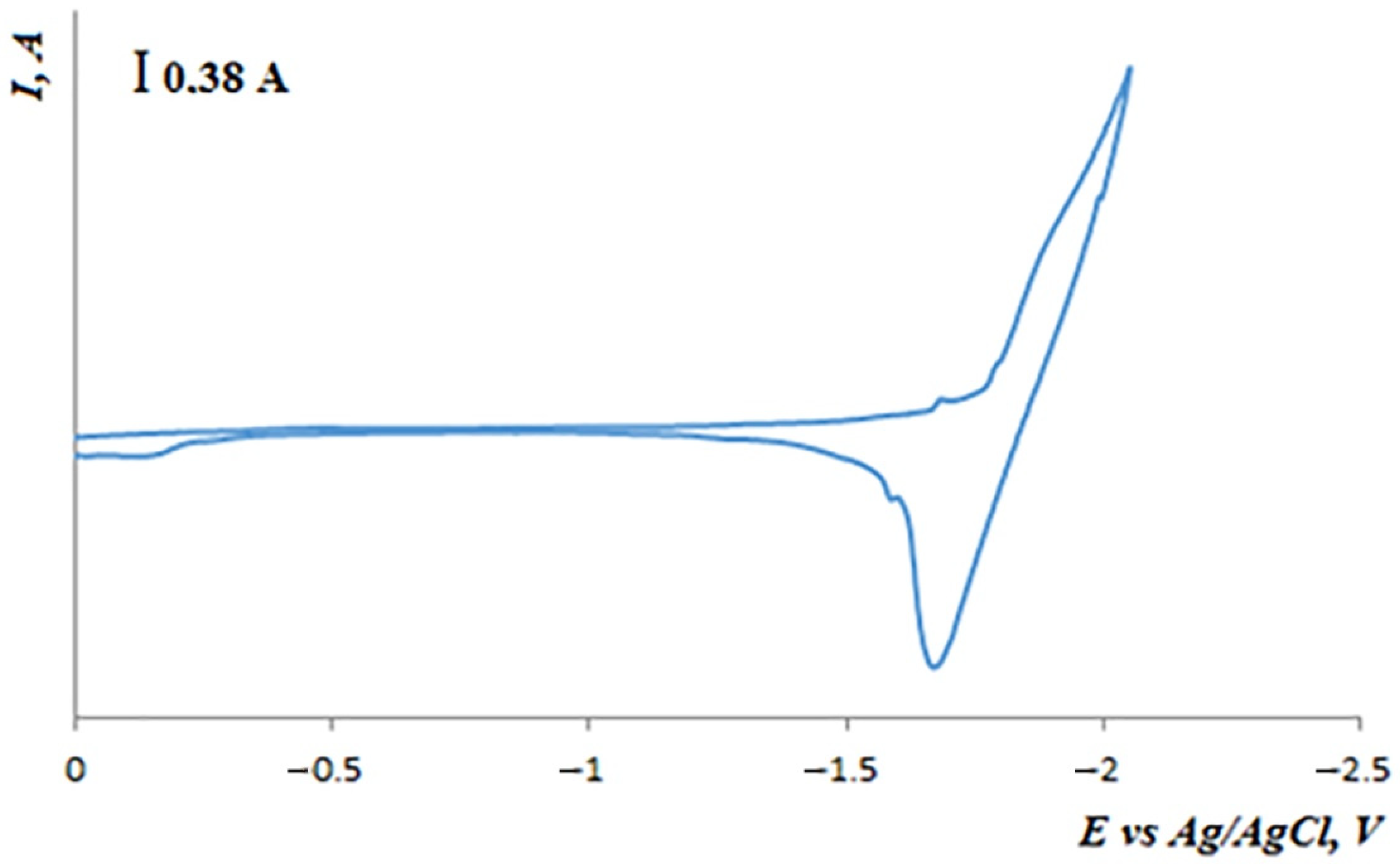
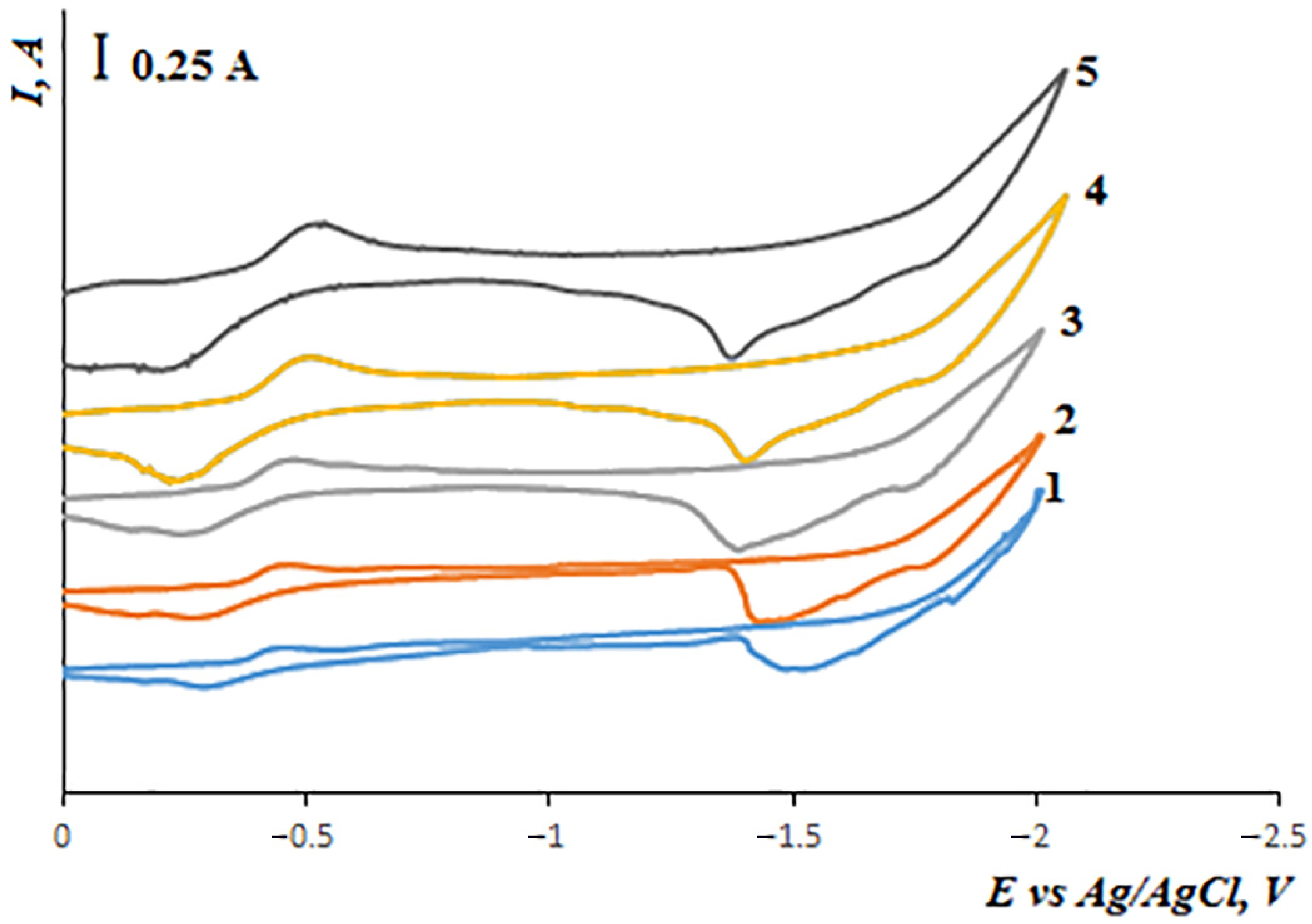
3.1. Electroreduction of Ho3+ Ions in the Equimolar KCl-NaCl Melt at 973 K

The cyclic voltammograms of the equimolar KCl-NaCl melt containing 1.0 mol.% of HoCl3 illustrate a well-reproducible wave of holmium ion electroreduction in the region of potentials ranging from 1.8 to 2.0 V (Figure 1).
Electroreduction of holmium ions on the tungsten electrode in the molten KCl-NaCl mixture at 973 K was studied at different polarization rates ranging from 0.05 to 1.0 V/s (Figure 2). As the potential sweep increases, the wave corresponding to the Ho3+ reduction shifts to the negative region and the height of the wave increases. A clearly observed cathode peak was not detected on the cyclic voltammograms. This is obviously explained by the significantly negative region of the Ho3+ reduction potentials, which are close to the potentials of the background electrolyte decomposition.
At different potential sweep rates, one wave of holmium ion electroreduction and one wave of cathode product oxidation were observed on the cathode and anode branches.
To determine the mechanism and character of the electroreduction of holmium ions in the KCl-NaCl-HoCl3 melt, the voltammetry dependencies were analyzed using the diagnostic criteria. We calculated the density of the current peak and determined the potentials of the peaks and half-peaks and the values of the peak half-width at different HoCl3 concentrations and potential sweep rates. The numerical values of these parameters are presented in Table 1.
Therefore, considering the structure of the chloride melts containing holmium ions [25], it was found that Ho3+ ions exist in the form of HoCl63− chloride complexes; a reversible three-electrode reaction of the electrochemical cathode reduction has the following form:
HoCl63− + 3e ↔ Ho + 6Cl

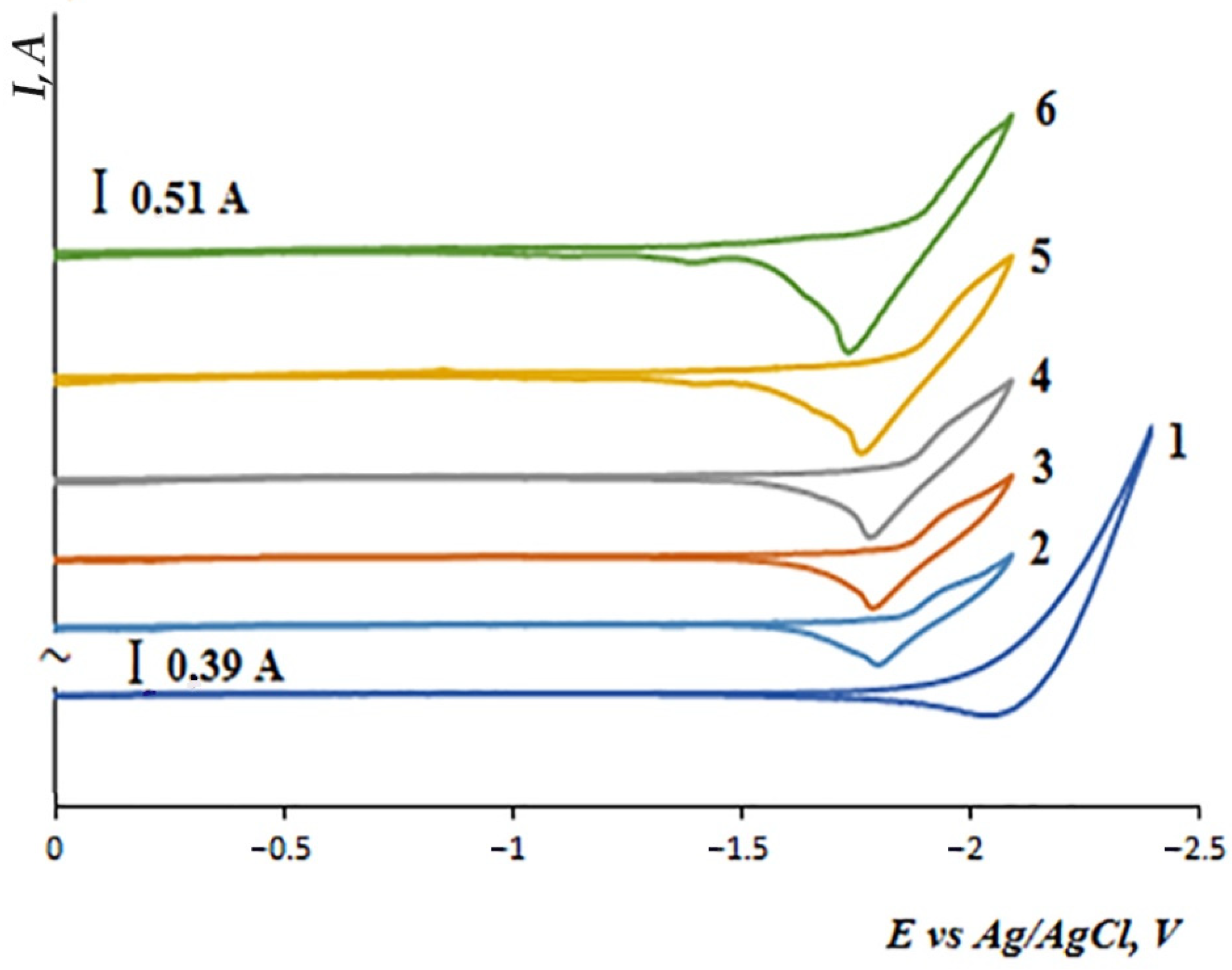
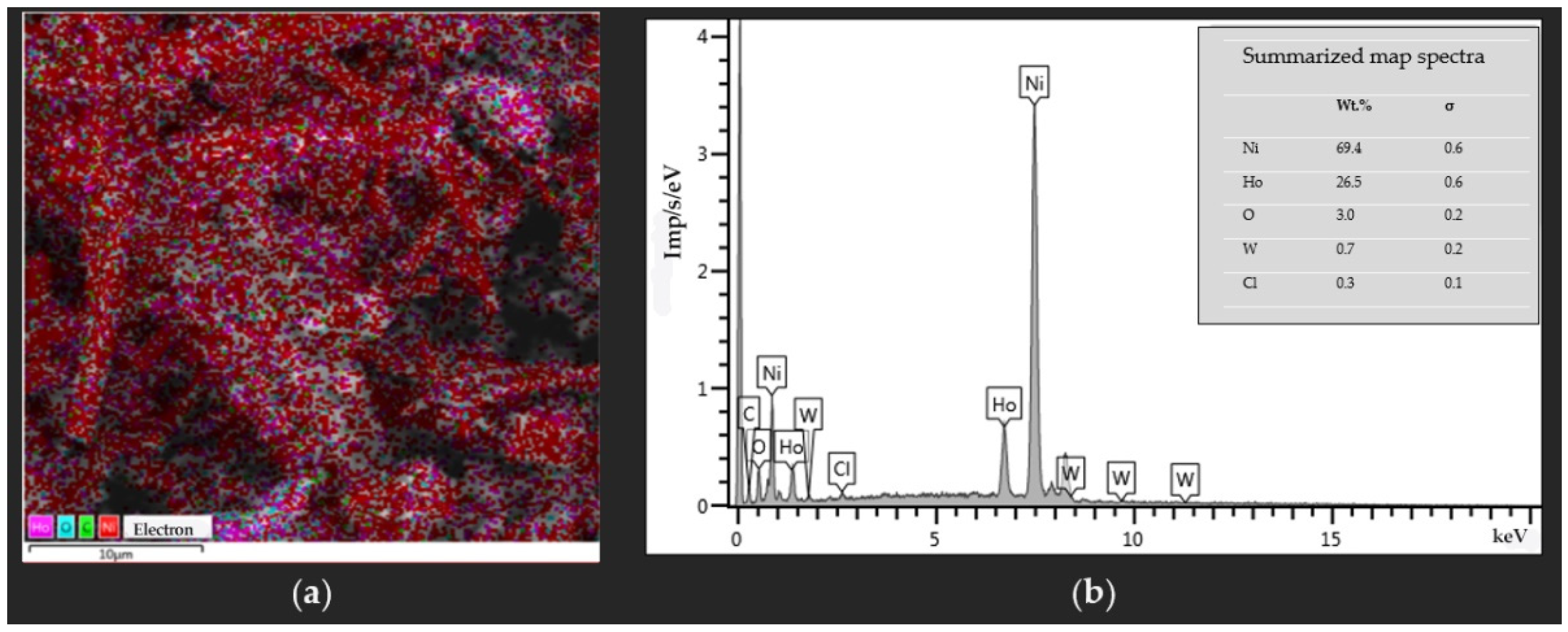
3.2. Co-Reduction of Ho3+ and Ni2+ Ions in the KCl-NaCl Equimolar Melt at 973 K

There is data on the formation of a number of HoxNiy compounds in the Ho-Ni system: HoNi, Ho Ni 2 , Ho Ni 3 , HoNi5, Ho3Ni, and Ho2Ni7 [30].
To determine the possibility of the electrochemical synthesis of these intermetallic compounds, we studied the processes of holmium and nickel ion co-reduction in the equimolar KCl-NaCl melt.
Figure 3 illustrates the cyclic voltammograms recorded on the tungsten electrode in the equimolar KCl-NaCl melt containing HoCl3 and NiCl2 at 973 K and at different reverse potentials, corresponding both to the potential of nickel electrodeposition −(0.1–0.2) V and to the potential of holmium electrodeposition −(1.8–2.0) V relative to the chlorine-silver reference electrode. For the experiments on the nickel and holmium ion co-reduction in the molten KCl-NaCl mixture, the NiCl2 concentration (0.25 mol.%) added to the melt was less than the HoCl3 concentration (1.5 mol.%). This is why the electrochemical reduction current of the Ni2+ ions in the KCl-NaCl-HoCl3-NiCl2 melt is smaller than that of the Ho3+ ion reduction.
The cathode branch of the cyclic voltammogram (Figure 3, curve 4) has five reduction waves. The appearance of wave A is associated with the reduction of Ni2+ ions, which is in good agreement with the data reported in [22]. Waves B, C, and D correspond to the co-reduction of Ho3+ and Ni2+ ions on metallic nickel, which was preliminary extracted with a definite depolarization on the tungsten electrode. Wave E is associated with the reduction of Ho3+ ions in the HoxNiy intermetallic phase. The anode branch of the cyclic voltammogram also has five waves of the cathode branch oxidation. The correspondence between the cathode reduction waves and anode waves of the cathode product electrooxidation is proved by the voltammetry curves recorded before different reverse potentials, which are associated with the termination of each phase of the cathode reduction wave (Figure 3).
Figure 4 illustrates that the increase in the polarization rate from 0.05 to 1.0 V/s results in an increase in the height of the electroreduction waves. In addition, the cathode wave shifts to the region of negative potentials and the anode wave shifts to the region of positive values.
It is observed that the reduction waves that were observed on the voltammograms at different potentials correspond to the processes of intermetallic compound formation. The phases with the largest holmium concentrations correspond to the reduction waves at the most negative potentials. Apart from this, the potentials of nickel and holmium deposition on the tungsten electrode coated with the preliminary deposited nickel differ by more than 1.0 V. This is why electrolysis of the intermetallic compounds based on holmium and nickel is possible only in the kinetic regime [9].
Electrochemical synthesis of holmium and nickel intermetallic compounds was performed in the KCl-NaCl-HoCl3-NiCl2 melt under a galvanostatic regime. The electrolysis was carried out in a high-temperature quartz cell in an argon atmosphere at 973 K. A high-purity tungsten rod of 3 mm in diameter served as the cathode. A glassy carbon crucible was used as the anode and as a container for the melt.
During the electrolysis of the molten KCl-NaCl mixture containing holmium trichloride (0.5 ÷ 2.5 mol.%) and nickel dichloride (0.1 ÷ 2.5 mol.%), a metal-salt “pear-shaped” object formed on the tungsten electrode at the current density of 0.5 ÷ 2.0 A/cm2. The end product in the majority of cases fell from the tungsten cathode onto the alundum support located at the bottom of the crucible.
After multiple rinses in distilled water, the deposit was dried in a vacuum drier at temperatures of 373–423 K. The phase composition of the cathode deposit is illustrated in Figure 5 and Table 2. The ratio of the metallic nickel and intermetallic HoNi, HoNi5, and HoNi3 phases depends on the composition of the electrolysis bath and the electrolysis parameters.
To determine the optimal concentrations of HoCl3 and NiCl2, we need to consider that during the first synthesis stage, the most electropositive component, i.e., nickel, is deposited. The electroreduction of holmium ions starts when nickel chloride is nearly consumed. The optimal concentration of nickel chloride is about 0.5 mol.%. At higher concentrations of nickel chloride, the deposit contains metallic nickel. The dependence of the cathode deposit composition on the nickel and holmium chloride concentrations and their ratio in the KCl-NaCl (1:1) melt were studied (Table 2).
The concentration of the intermetallic compounds increases both as the concentration of holmium chloride in the melt increases and as the concentration ratio of the holmium and nickel chlorides increases. The metallic nickel phase prevails in the cathode deposit when the concentration ratio is [HoCl3]:[NiCl2] = 1:1. As the ratio increases, the fraction of the metallic nickel decreases and the concentration of the intermetallic HoNi, HoNi3, and HoNi5 compounds increases. When [HoCl3]:[NiCl2] = 5:1, the metallic nickel phase is not detected in the cathode deposit. The mixture of intermetallic phases with a large holmium concentration is formed.
Color mapping of the studied intermetallic samples’ surfaces according to the X-ray spectra illustrates the distribution of intermetallic compounds (Figure 6a). Simultaneously, we obtained the information on the qualitative and quantitative elemental analysis (Figure 6b).

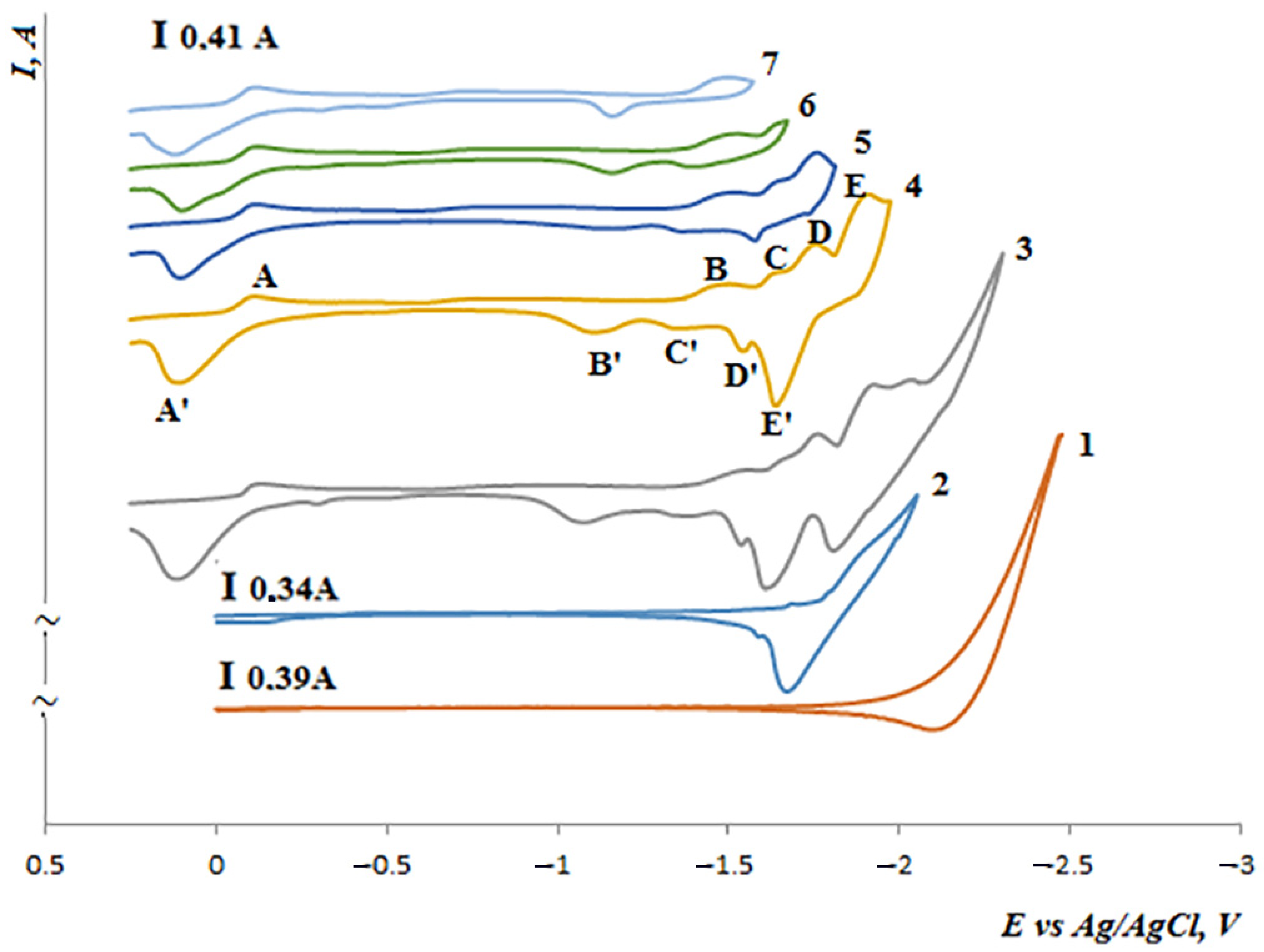
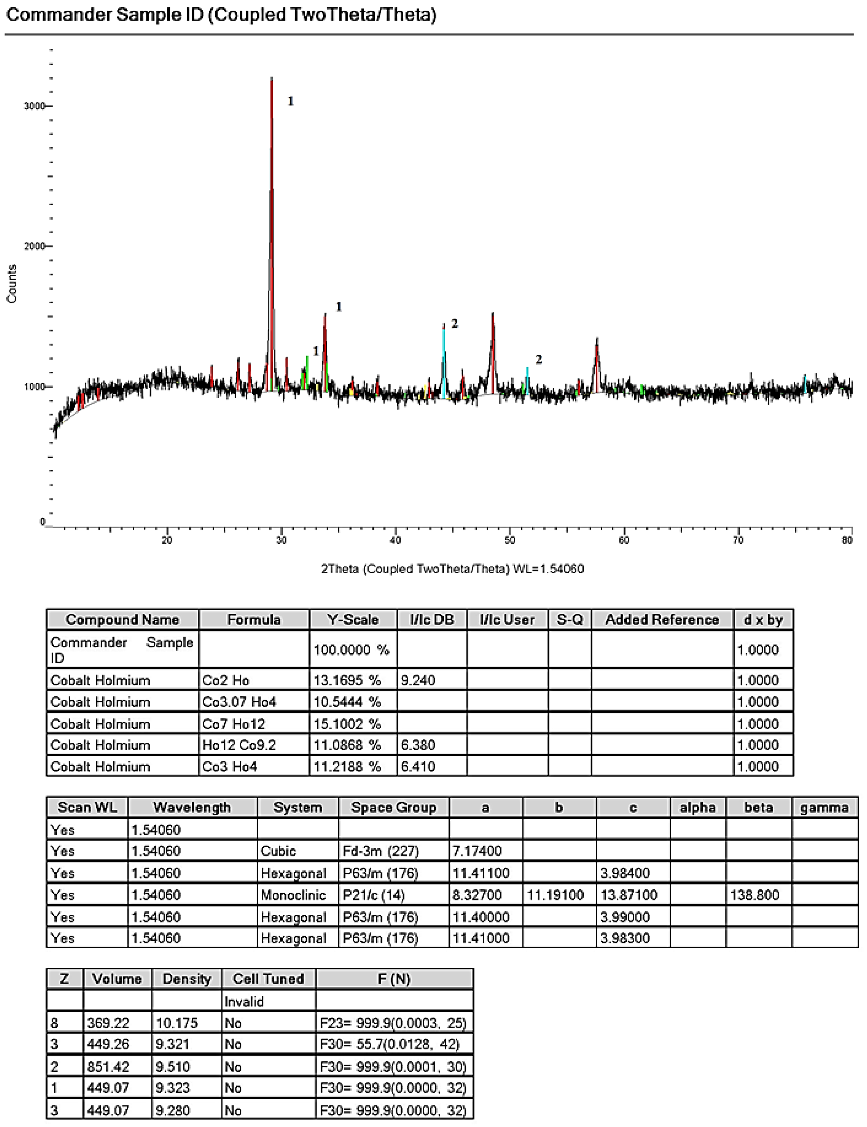
3.3. Co-Reduction of Ho3+ and Co2+ Ions in the Equimolar KCl-NaCl Melt at 973 K

The equilibrium diagram of Ho3+ and Ni2+ ions was studied over the whole concentration range [30].
The formation of eight compounds was determined in the Ho-Co system. Three compounds Co 17 Ho 2 (1370 °C), Co 3 Ho (1390 °C), and Co 7 Ho 12 (795 °C) form in the melt, and four compounds form according to the peritektic reactions [30]:
Ж +   Co 17 Ho 2     Co 5.5 Ho   at   1355   ° C
Ж +   Co 3 Ho     Co 7 Ho 2   at   1365   ° C
Ж +   Co 3 Ho     Co 2 Ho   Ho   at   1330   ° C
Ж + Ho     CoHo 3   Ho   at   895   ° C
The Co 5.5 compound exists in a narrow temperature interval of 1355–1150 °C. The phase Co 3 Ho 4 is formed according to the peritektic reaction [30]:
Co 7 Ho 12   +   Co 2 Ho     Co 3 Ho 4   at   755   ° C
The mutual solubility of components in a solid state is nearly absent. Four eutectics crystallize in the system:
Co Ho 3 + Co 7 Ho 12   at   770   ° C
Co 7 Ho 12 + Co 2 Ho   at   755   ° C
Co 7 Ho 2 + Co 5.5 Ho   at   1340   ° C
Co 17 Ho 2 + ( α Co )   at   1345   ° C
Figure 7 illustrates the cyclic voltammograms of the equimolar KCl-NaCl melt containing cobalt chloride (0.25 mol.%) and holmium chloride (1.0 mol.%). As the polarization rate increases from 0.05 to 1.0 V/s, the reduction waves grow. The cathode wave shifts to the region of negative values of the potential and the anode wave shifts to the region of positive values. The cathode branch of the voltammogram has four waves of electroreduction: wave A corresponds to the electroreduction of Co2+ ions and waves B and C illustrate the co-reduction of Co2+ and Ho3+ ions with the following formation of intermetallic compounds of various compositions. On the anode part, the dissolution of cobalt (A′) and holmium and cobalt intermetallic compounds (B′, C′) corresponds to the electroreduction waves (A, B, and C). Wave D illustrates the reduction of HoCl63− ions on the tungsten electrode preliminary coated with the HoxCoy phases. Wave D′ illustrates the anode dissolution of metallic holmium.
A distinctive feature of the holmium trichloride reduction wave is that when cobalt chloride is present in the melt, holmium is deposited on the tungsten electrode coated with metallic cobalt. Due to this, the holmium ion reduction wave becomes more prolonged along the axis of potentials and shifts to the region of more positive potentials (Figure 7). The observed depolarization of holmium deposition is associated with the formation of holmium and cobalt intermetallic compounds. The voltammetry measurements illustrate that the potentials of cobalt and holmium extraction on the tungsten electrode coated by the preliminary extracted cobalt differ by more than 1.0 V. This is why the electrolysis of the intermetallic compounds based on holmium and cobalt is possible only under a kinetic regime. In addition, the concentration of cobalt ions should not be excessively large, because at high values of the limiting current of the more electropositive component, i.e., cobalt, the electrochemical reduction current of holmium cannot be achieved.
Electrochemical synthesis of holmium and cobalt intermetallics was performed under a galvanostatic regime in the KCl-NaCl-HoCl3-CoCl2 melt. The X-ray pattern of the cathode deposit and crystallographic parameters of the obtained phases are presented in Figure 8. Depending on the composition of the electrolysis bath and electrolysis parameters, the mixture of the metallic cobalt and intermetallic HoCo2, HoCo3, HoCo5, and Ho2Co17 phases was obtained.
To determine the optimum concentrations of HoCl3 and CoCl2, we need to consider that cobalt, being the most electropositive component, is deposited during the first stage of synthesis. The electroreduction of holmium ions starts when cobalt chloride is nearly consumed. The optimum concentration of cobalt chloride is about 0.5 mol.%. At the higher concentrations of cobalt chloride, the deposit contains metallic cobalt. The dependence of the cathode deposit composition on the HoCl3 and CoCl2 concentrations and their ratio in the KCl-NaCl (1:1) melt is presented in Table 3.
The structure, morphology, and elemental composition of the obtained samples were quantitatively and qualitatively studied using a scanning emission electron microscope VEGA3 LMH. The obtained images testify that the electrolytic co-reduction of holmium and cobalt and electrochemical synthesis of HoxCoy intermetallic compounds are possible (Figure 8 and Figure 9).

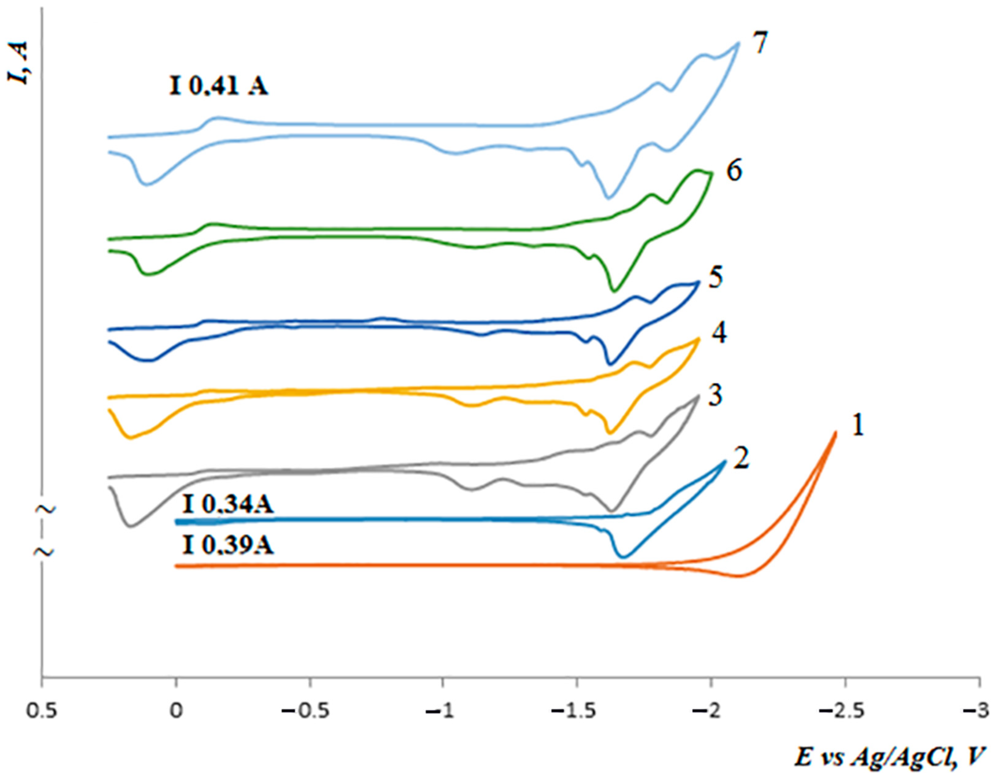
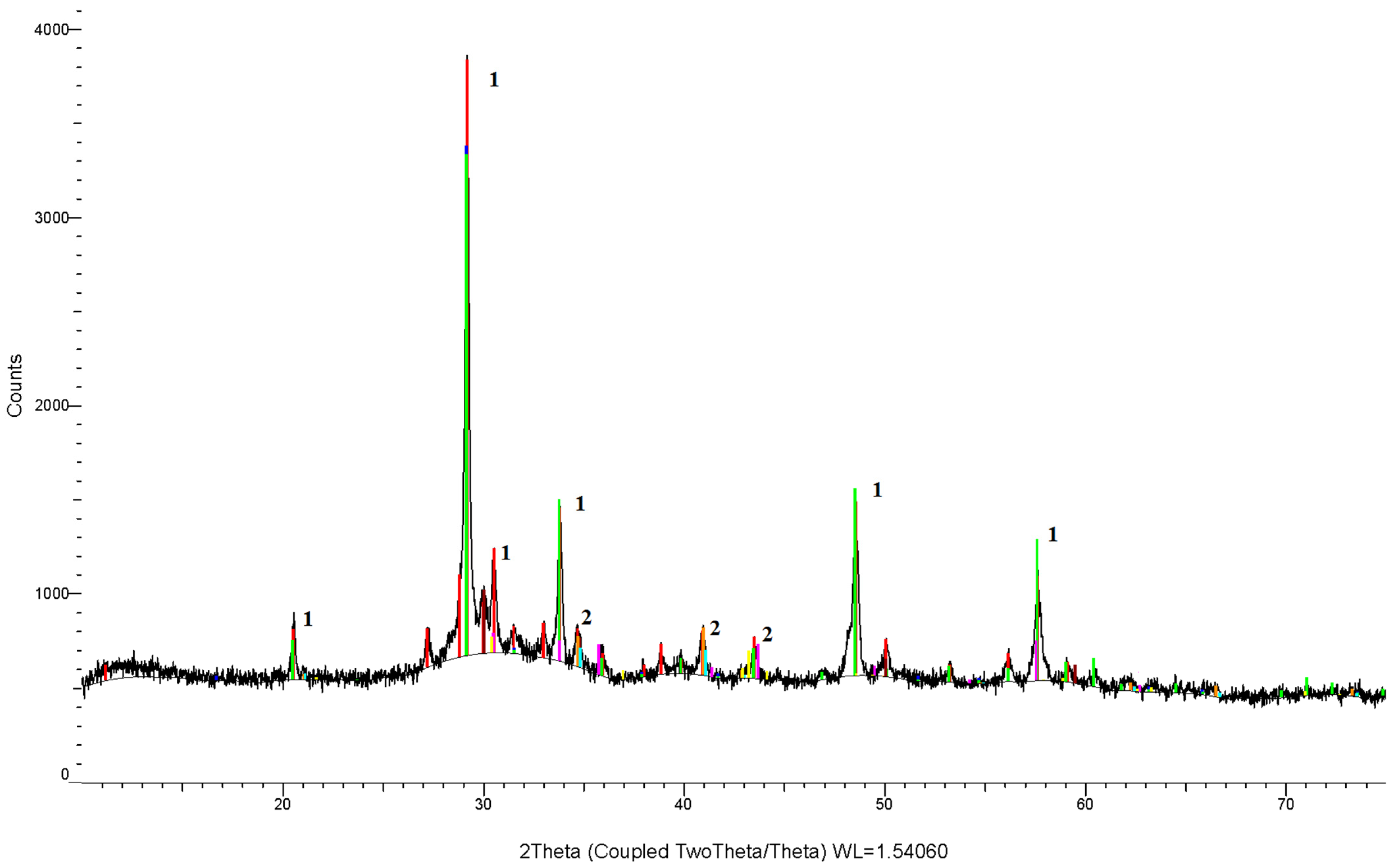
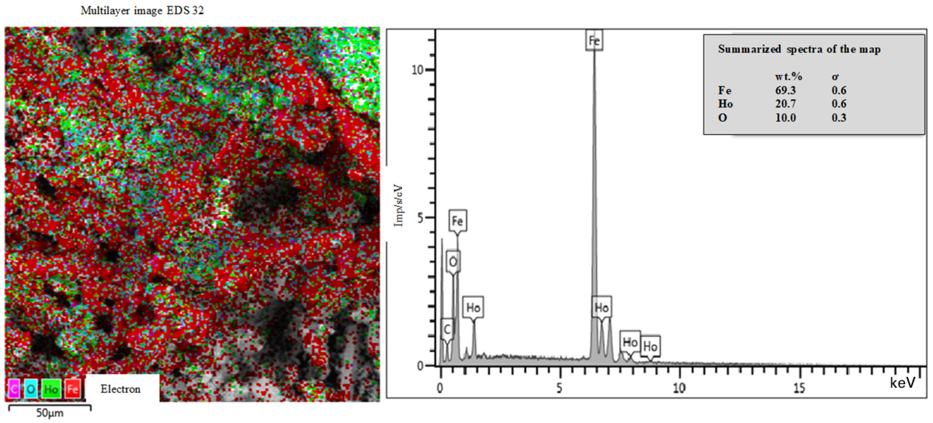
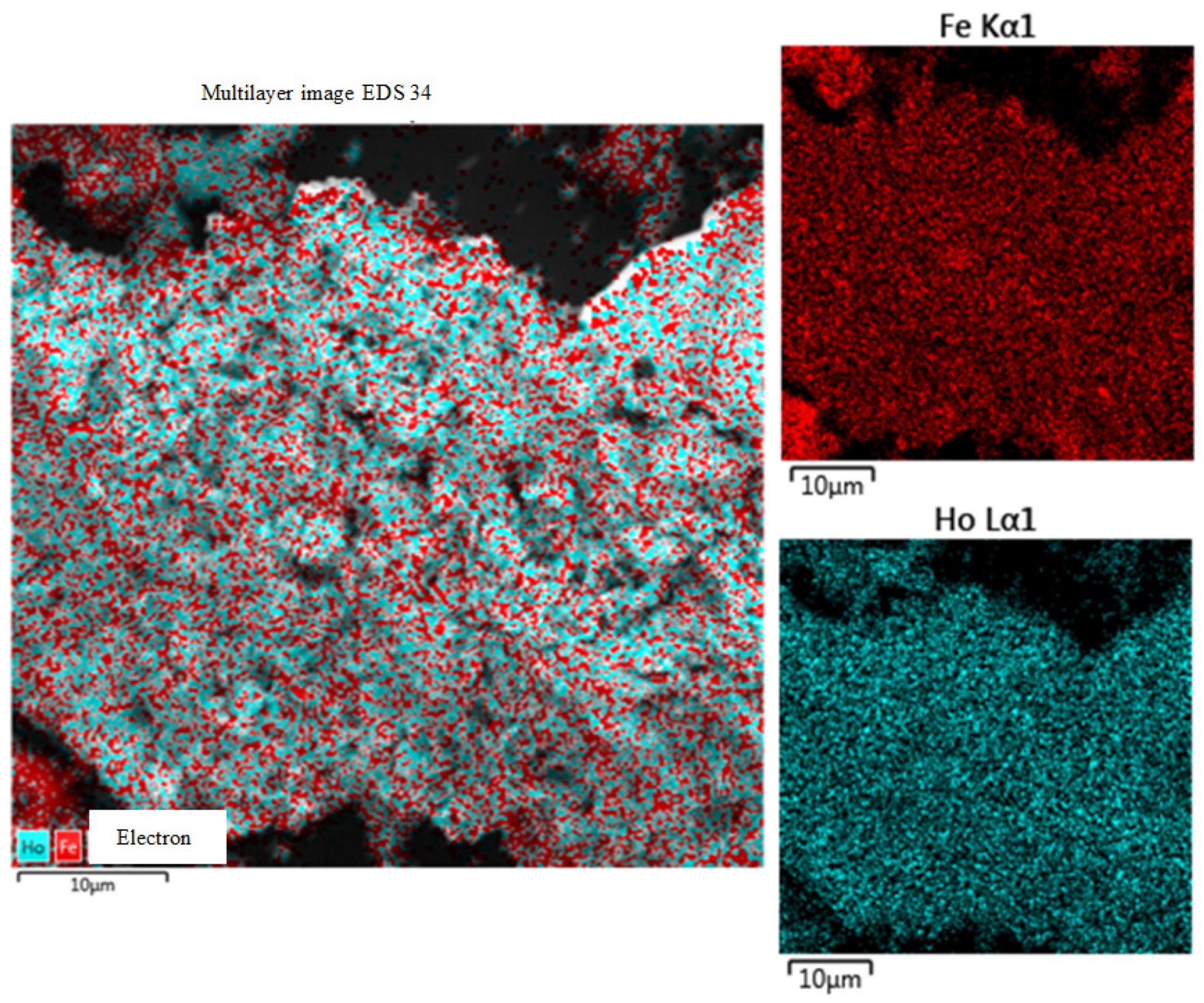
3.4. Electrolytic Co-Reduction of Ho3+ and Fe3+ Ions in the Equimolar KCl-NaCl Melt at 973 K

Alloys of the Fe-Ho systems were studied in detail in [31]. The equilibrium diagrams of the Fe-Ho system are provided in [32]. In addition, according to [30], the assumption regarding the polymorphic transformation of Ho and the associated reactions should not be considered.
Four compounds are formed in the Fe-Ho system [30]. Two compounds, Fe 17 Ho 2 and Fe 23 Ho 6 , are formed in the melt on the peaks of the phase diagram of the Fe-Ho system at 1343 and 1332 °C, respectively [30]. Another two compounds, Fe 3 Ho and Fe 2 Ho , are formed according to the peritectic reactions:
Ж +   Fe 23 Ho 6     Fe 3 Ho   ( 1293   ° C )
Ж +   Fe 3 Ho     Fe 2 Ho   ( 1288   ° C )
However, (γFe)+   Fe 17 Ho 2 , Fe 17 Ho 2 + Fe 23 Ho 6 , and Fe 2 Ho +(Ho) eutectics were found to crystallize at the Fe (9.18 at.%) and Ho (63.4 at.%) concentrations and temperatures of 1338, 1285, and 875 °C, respectively. The mutual solubility of the components is almost absent.
To determine the conditions of the electrolytic co-reduction of holmium and iron, we performed voltammetry measurements in the equimolar KCl-NaCl melt containing iron and holmium trichlorides.
The cathode branch of the cyclic voltammogram (Figure 10) at the potentials −(0.5 ÷ 0.6) V has a wave of Fe3+ iron ion reduction. In the region of potentials −(1.6 ÷ 1.8) V, wave B is observed. The appearance of wave B is associated with the co-reduction of Ho3+ and Fe3+ ions on metallic iron preliminary deposited with a definite depolarization on the tungsten electrode and with the formation of HoxFey intermetallic compounds.
Unlike electrolytic co-reduction of Ho3+ ions with Ni2+ and Co2+, in the case of Ho3+ and Fe3+ ion co-reduction, the waves corresponding to the electroreduction of holmium and iron intermetallic compounds of various compositions are not observed on the cathode branch of the cyclic voltammogram. This is likely explained by the smaller value of the free energy of the formation of HoxFey intermetallic compounds as opposed to those of HoxNiy and HoxCoy intermetallic compounds. The values of the free energy of the formation of different phases of HoxFey intermetallic compounds also differ slightly. This is verified by the prolonged anode wave of the cathode product oxidation, having a tendency to duplicate along the axis of potential (Figure 11).
Figure 11 illustrates that the waves grow as the polarization rate increases from 0.05 to 1.0 V/s. The cathode wave shifts to the region of negative values of the potential and the anode wave shifts to the region of positive potentials.
High-temperature electrochemical synthesis of holmium and iron intermetallic compounds was performed in the KCl-NaCl-HoCl3 melt with holmium chloride concentrations of 0.5 ÷ 2.5 mol.%. An iron plate simultaneously served as an anode and the source of iron ions. The initial cathode current density ranged within the interval of 3.0–4.0 A/cm2. The real value of the current density during galvanostatic electrolysis is known only during the initial time period because the cathode area changes significantly during the electrolysis. However, we can clearly state that as the current density increases, the powder size increases. The electrolysis was performed for 60 min at 973 K.
To separate the end product of the reaction from the salt phase, cathode deposit leaching in hot distilled water and magnet treating were applied. The obtained pure holmium and iron intermetallic powders were characterized using X-ray diffraction and X-ray fluorescence methods. The results of the X-ray diffraction analysis are presented in Figure 12.
The structure, morphology, and elemental composition of the obtained samples were qualitatively and quantitatively studied using an electron scanning microscope VEGA3 LMH. The images illustrated in Figure 13 testify the presence of the holmium and iron co-reduction.
The greater iron concentration in the samples results in greater assimilation of the cathode deposits to the structure of metallic iron and in a greater particle size, caused by the formation of dendrites (Figure 14).

4. Conclusions

Based on the voltammetry studies of the Ni2+, Co2+, Fe3+, and Ho3+ ion co-reduction in the equimolar melt of potassium and sodium chlorides at 973 K, it was shown that electrochemical synthesis of holmium with iron triad metals may be performed under a kinetic regime. The activity of the iron triad metals during the interaction with metallic holmium that resulted in the intermetallic compound formation was found to decrease in a row as follows: nickel—cobalt—iron, where nickel was the most active metal.
It is demonstrated that depending on the electrolysis regime, potentiostatic or galvanostatic, the process of electrochemical synthesis has the following parameters. The metallic phases of nickel, cobalt, and iron are deposited on the cathode during galvanostatic electrolysis at current densities that do not exceed the limiting diffusion current densities of the Ni2+, Co2+, and Fe3+ ion reduction or during the potentiostatic electrolysis performed at potentials that do not exceed the limiting current densities of the Ni2+, Co2+, and Fe3+ ion electroreduction. Intermetallic nickel, cobalt, iron, and holmium phases form during potentiostatic electrolysis together with the phases of metallic nickel, cobalt, and iron at cathode current densities that exceed the limiting diffusion current densities of Ni2+, Co2+, and Fe3+ ion reduction at the potentials of the corresponding cyclic voltammetry waves. At a constant concentration of the holmium and iron triad chlorides in the equimolar KCl-NaCl melt, the higher cathode current densities and more negative electrolysis potentials result in a decrease in the concentration of the metallic phase in the cathode deposit and in an increase in the concentrations of both the holmium intermetallic phases and intermetallic phases with a high holmium concentration. Therefore, we state that the process of electrochemical synthesis of nickel, cobalt, iron, and holmium intermetallic compounds under a kinetic regime is determined by the following interconnected parameters: the composition of the electrolysis bath (concentrations of iron triad metal chlorides and holmium trichloride and their ratio), cathode current density, electrolysis potential (bath voltage), and electrolysis duration.

5. Patents

Kushkhov, K.; Kardanova R. Electrochemical Method for Holmium and Nickel Intermetallic Compounds Nanopowders Production in Halide Melts. Patent RU No. 2621508 C 2, dated 9 October 2015, published 6 June 2017 (2017).

Author Contributions

Conceptualization, K.K.; methodology, K.K.; validation, K.K.; formal analysis, K.K. and R.K.; investigation, R.K.; resources, K.K. and R.K.; data curation, R.K.; writing—original draft preparation, K.K. and R.K.; writing—review and editing, K.K., R.K. and A.K.; visualization, R.K.; supervision, K.K.; project administration, A.K.; funding acquisition, K.K. and A.K. All authors have read and agreed to the published version of the manuscript.

Funding

This research was performed within the budget themes of the Institute of High Temperature Electrochemistry and Kabardino-Balkarian State University.

Institutional Review Board Statement

Not applicable.

Informed Consent Statement

Not applicable.

Data Availability Statement

Not applicable.

Acknowledgments

The authors are grateful to Daria Mirzayants for translation and manuscript preparation.

Conflicts of Interest

The authors declare no conflict of interest.

References

  1. Il’yin, A.A.; Il’yin, A.P.; Kurochkin, V.Y. Study of the physicochemical properties of iron oxide catalysts promoted by lanthanides (Issledovaniye fisico-khimicheskikh svoistv zheleznooksidnykh catalyzatorov, promotirovannykh lantanoidov). Izv. Vyss. Uchebnykh Zaved. Seriya “Khimiya Khimicheskaya Tekhnologiya” 2010, 53, 90–93. (In Russian) [Google Scholar]
  2. Bushuyev, A.N.; Yelkin, O.V.; Tolstoborov, I.V.; Kondratiyev, D.A. Production of nickel-neodymium intermetallic compound in the equimolar NaCl-KCl melt (Polucheniye intermetallicheskogo soedineniya nickel-neodim v ekvimolnom rasplave NaCl-KCl). Adv. Sci. 2017, 2, 8. (In Russian) [Google Scholar]
  3. Ganchenkova, M.G.; Borodin, V.A.; Binyukova, S.Y.; Gonzalez, E.A.; Jasen, P.V.; Juan, A. Advanced materials for hydrogen storage based on iron-palladium intermetallic alloys. Inorg. Mater. Appl. Res. 2011, 2, 172–175. [Google Scholar] [CrossRef]
  4. Itin, V.I.; Nayborodenko, Y.S. High Temperature Synthesis of Intermetallic Compounds; Tomsk University Publishing: Tomsk, Russia, 1989; p. 161. (In Russian) [Google Scholar]
  5. Martin, D.L.; Elnora, N.Y. Nickel-Lanthanum Alloy Produced by a Reduction-Diffusion Process. U.S. Patent 3,918,933, 11 November 1975. [Google Scholar]
  6. Martin, D.L.; Elnora, N.Y. Nickel-Lanthanum Alloy Produced by a Reduction-Diffusion Process. U.S. Patent 3,883,346, 13 May 1975. [Google Scholar]
  7. Kamarzin, A.A.; Osadchaja, L.I.; Podojnitsyn, S.V.; Stonoga, Y.A.; Zelenin, Y.M.; Bondin, V.V. Method of Preparing Composition for Hydrogen Accumulation. RU Patent 2,113,400, 20 June 1998. [Google Scholar]
  8. Kasimtsev, A.V. Method for Making Reversible Hydrogen-Sorbing Alloy Combination. RU Patent 2,351,534, 10 April 2009. [Google Scholar]
  9. Shapoval, V.I.; Malyshev, V.V.; Novoselova, I.A.; Kushkhov, K.B. Modern problems in the high-temperature electrochemical synthesis of the compounds of Group IV–VI transition metals. Russ. Chem. Rev. 1995, 64, 125–132. [Google Scholar] [CrossRef]
  10. Kushkhov, K.B.; Tlenkopachev, M.R. Electrochemical Synthesis of Intermetallic and Refractory Compounds Based on Rare-Earth Metals in Ionic Melts: Achievements and Prospects. Russ. J. Gen. Chem. 2021, 91, 251–272. [Google Scholar] [CrossRef]
  11. Qiqin, Y. Electrochemistry of deposition of rare earth metals and their alloys in molten salts. In Proceedings of the 6th International Symposium on Molten Salt Chemistry and Technology, Shanghai, China, 8–13 October 2001; pp. 383–390. [Google Scholar]
  12. Su, Y.Z.; Yang, Q.Q.; Liu, G.K. Electroreduction of Ho3+ on nickel cathode in molten KCl-HoCl3. J. Rare Earths 2000, 18, 34–38. [Google Scholar]
  13. Yang, Q.Q.; Liu, G.K.; Su, Y.Z. Electroreduction of Holmium ion on iron electrode in molten chlorides. J. Electrochem. 1995, 1, 44–49. (In Chinese) [Google Scholar]
  14. Mamantov, M.; Manning, D.L.; Dale, J.M. Reversible deposition of metals on solid electrodes by voltammetry with linearyvaring potential. J. Electroanal. Chem. 1965, 9, 253–259. [Google Scholar]
  15. Kabanov, B.N.; Astakhov, I.I.; Kiseleva, I.G. Formation of crystalline intermetallic compounds and solid solutions in electrochemical incorporation of metals into cathodes. Electrochim. Acta 1979, 24, 167–171. [Google Scholar] [CrossRef]
  16. Vindizheva, M.K.; Mukozheva, R.A.; Tlenkopachev, M.R.; Kushkhov, K.B. Electrochemical synthsis of intermetallics based on samarium and cobalt in ionic melts (Elecktrokhimicheskiy syntez intermetallidov na osnove smamriya y cobalt v ionnykh rasplavakh). Perspect. Mater. 2010, 9, 255–257. (In Russian) [Google Scholar]
  17. Kushkhov, K.B.; Vindizheva, M.K.; Mukozheva, R.A.; Kalibatova, M.N. Electrochemical synthesis of disperse lanthanum boride powders from halide melts (Electrokhimicheskiy sintez dispersnykh poroshkov boridnykh faz lantana iz galoguenidnikh rasplavov). Izv. Vyss. Ychebnykh Zavedeniy. Poroshkovaya Metall. Functsionalniye Pokrytiya 2014, 2, 11–16. (In Russian) [Google Scholar]
  18. Kushkhov, K.B.; Vindizheva, M.K.; Mukozheva, R.A.; Abazova, A.K.; Kyarova, Z.K. Investigation of the mechanism of zerium and fluoroborate ions electroreduction on the tungsten cathode and synthesis of their compounds in the K, Na, Cs/Cl eutectics at 873 K. Izv. Kabard.-Balk. Gos. Univ. 2016, 6, 52–59. (In Russian) [Google Scholar]
  19. Liu, L.; Tong, Y.; Yang, Q. Electroreduction Co(II), Ni(II), and codeposition with La(III) in in urea-NaBr melt. Rare Metals 2000, 19, 237–241. [Google Scholar]
  20. Kushkhov, K.B.; Kardanova, R.A. Electrochemical Method for Holmium and Nickel Intermetallic Compounds Nanopowders Production in Halide Melts. RU Patent 2621508C2, 6 June 2017. [Google Scholar]
  21. Su, L.L.; Liu, K.; Liu, Y.L.; Wang, L.; Yuan, L.Y.; Wang, L.; Li, Z.J.; Zhao, X.L.; Chai, Z.F.; Shi, W.Q. Electrochemical behaviors of Dy(III) and its co-reduction with Al(III) in molten LiCl−KCl salts. Electrochim. Acta 2014, 147, 87–95. [Google Scholar] [CrossRef]
  22. Kushkhov, K.; Ali, Z.; Khotov, A.; Kholkina, A. Mechanism of Dy3+ and Nd3+ Ions Electrochemical Coreduction with Ni2+, Co2+, and Fe3+ Ions in Chloride Melts. Materials 2021, 14, 7440. [Google Scholar] [CrossRef] [PubMed]
  23. Liu, K.; Liu, Y.L.; Yuan, L.Y.; Wang, L.; Li, Z.J.; Chai, Z.F.; Shi, W.Q. Thermodynamic and electrochemical properties of holmium and HoxAly intermetallic compounds in the LiCl−KCl eutectic. Electrochim. Acta 2015, 174, 15–25. [Google Scholar] [CrossRef]
  24. Castrillejo, Y.; Bermejo, M.R.; Barrado, E.; Medina, J.; Martinez, M. Electrodeposition of Ho and Electrochemical Formation of Ho-Al Alloys from the Eutectic LiCl–KCl. J. Electrochem. Soc. 2006, 153, 713–721. [Google Scholar] [CrossRef]
  25. Yin, T.-Q.; Xue, Y.; Yan, Y.; Ma, Z.C.; Ma, F.-Q.; Zhang, M.-L.; Wang, G.-L.; Qiu, M. Recovery and separation of rare earth elements by molten salt electrolysis. Int. J. Miner. Metall. Mater. 2021, 28, 899–914. [Google Scholar]
  26. Chernova, O.V.; Zhukovin, S.V.; Kondrat’ev, D.A. Electroreduction of Holmium Chloride in the Equimolar NaCl–KCl Melt. Russ. Metall. 2020, 102–106. [Google Scholar]
  27. Volkov, S.V.; Grishenko, V.F.; Delimarskyi, Y.K. Coordination Chemistry of Molten Melts (Koordinatsionnaya Khimiya Solevykh Rasplavov); Naukova Dumka: Kiev, Ukraine, 1977; 332p. [Google Scholar]
  28. Sytchev, J.; Kushkhov, H.; Sychev, J. Voltammetric investigation of the reduction processes of nickel cobalt and iron ions in chloride and chloro–fluoride melts. In Proceedings of the International Computer Science Conference, Miskolc, Hungary, 22–24 February 2000. [Google Scholar]
  29. Kushkhov, H.B.; Supatashvili, D.G.; Shapoval, V.I.; Novoselova, I.A.; Gasviana, N.A. Co-reduction of molybdate ion with Ni and Co cations in chloride melts (Sovmestnoye electrovosstanovleniye molybdat iona s cationami Ni y Co v khloridnykh rasplavakh). Elektrokhimiya 1990, 26, 300–304. (In Russian) [Google Scholar]
  30. Lyakisheva, N.M. Phase Diagrams of Double Metallic Systems: Reference Book (Diagramma Sostoyaniy Dvoinykh Metallicheskihk System: Spravochnik); Book 1; Mashinostroyeniye: Moskva, Russia, 1999; Volume 3. (In Russian) [Google Scholar]
  31. Gladyshevskiy, Y.I.; Bodak, O.I. Crystalline Chemistry of Rare-Earth Metals Intermetallic Compounds (Crystallokhimiya Intermetallicheskikh Soedineniy Redkozemelnykh Metallov); Vysshaya Shkola: Lvov, Ukraine, 1982. (In Russian) [Google Scholar]
  32. Kubaschewski von Goldbeck, O. Iron—Binary Phase Diagrams; Springer: Berlin/Heidelberg, Germany, 1982. [Google Scholar]
Figure 1. Cyclic voltammogram of the KCl-NaCl-HoCl3 melt recorded on the tungsten electrode. C(HoCl3) = 1.0 mol.%. The polarization rate was 0.2 V/s; T = 973 K; S = 0.77 cm2.
Processes 10 01723 g001
Figure 2. Cyclic voltammograms of the KCl-NaCl-HoCl3 melt recorded on the tungsten electrode at different polarization rates V, V/s: 1—KCl-NaCl background electrolyte, 0.2; 2—0.05; 3—0.1; 4—0.2; 5—0.5; 6—1.0. C(HoCl3) = 1.0 mol.%; T = 973 K; S = 0.77 cm2.
Processes 10 01723 g002
Figure 3. Cyclic voltammograms of the KCl-NaCl-HoCl3–NiCl2 melt recorded on the tungsten electrode at different reverse potentials—E, V: 1—2.45 (KCl-NaCl); 2—2.15; 3—2.3; 4—1.97; 5—1.81; 6—1.67; 7—1.57. C (HoCl3) = 1.5 mol.%, C(NiCl2) = 0.25 mol.%. V = 0.2 V/s. T = 973 K. S = 0.7 cm2.
Processes 10 01723 g003
Figure 4. Cyclic voltammograms of the KCl-NaCl-HoCl3–NiCl2 melt on the tungsten electrode at different polarization rates V, V/s; 1—(KCl-NaCl, 0.2); 2—(HoCl3, 0.2); 3—0.05; 4—0.1; 5—0.2; 6—0.5; 7—1.0. C (HoCl3) = 1.5 mol.%, C(NiCl2) = 0.25 mol.%; T = 973 K; S = 0.7 cm2.
Processes 10 01723 g004
Figure 5. X-ray diffraction pattern of the galvanic electrolysis product obtained on the tungsten electrode in the equimolar KCl-NaCl melt containing HoCl3 = 2.5 mol.% and NiCl2 = 0.5 mol.%. ik = 1.2 A/cm2; T = K; S = 2.43 cm2. Standard lines: 1—HoNi, 2—HoNi5, 3—HoNi3.
Processes 10 01723 g005
Figure 6. (a) Color map of the elemental distribution at the surface of the sample containing holmium and nickel intermetallics; (b) elemental analysis of the sample obtained by galvanostatic electrolysis of the equimolar KCl-NaCl melt containing HoCl3 = 2.5 mol.% and NiCl2 = 0.5 mol.% on the tungsten electrode. ik = 1.2 A/cm2. T = 973 K. S = 2.43 cm2.
Processes 10 01723 g006
Figure 7. Cyclic voltammograms of the KCl-NaCl-HoCl3-CoCl2 melt on the tungsten electrode at different polarization rates V, V/s: waves 1, 2, 4—0.1; wave 3—0.05; wave 5—0.2; C (HoCl3), mol.%: wave 1—0; waves 2–5—1.0; C (CoCl2), mol.%: waves 1, 2—0; waves 3–5—0.25. T = 973 K. S = 0.69 cm2.
Processes 10 01723 g007
Figure 8. X-ray pattern of the deposit obtained on the tungsten cathode by galvanostatic electrolysis of the equimolar KCl-NaCl melt containing 2.0 mol.% HoCl3 and 0.5 mol.% CoCl2. Crystallographic parameters of the obtained phases.
Processes 10 01723 g008
Figure 9. Color map and elemental analysis of the Ho2Co17 sample obtained on the tungsten electrode in the equimolar KCl-NaCl melt containing HoCl3 (2.0 mol.%) and CoCl2 (0.5 mol.%). ik = 1.2 A/cm2; T = 973 K; S = 1.48 cm2.
Processes 10 01723 g009
Figure 10. Cyclic voltammograms of the KCl-NaCl-HoCl3-FeCl3 melt recorded on the tungsten electrode at different reverse potentials—E, V: 1—2.4; 2—2.15; 3—1.95; 4—1.7; 5—0.575. C (FeCl3) = 0.75 mol.%, C (HoCl3) = 1.5 mol.%; V = 0.2 V/s; T = 973 K; S = 0.65 cm2.
Processes 10 01723 g010
Figure 11. Cyclic voltammograms of the KCl-NaCl-HoCl3–FeCl3 melt on the tungsten electrode at different potential sweep rates V, V/s: 1—0.05; 2—0.1; 3—0.2; 4—0.5; 5—1.0. C (HoCl3) = 1.5 mol.%, C (FeCl3) = 0.75 mol.%; T = 973 K; S = 0.65 cm2.
Processes 10 01723 g011
Figure 12. X-ray pattern of the deposit obtained on the tungsten cathode by galvanostatic electrolysis of the KCl-NaCl-HoCl3 melt using a soluble iron anode. C (HoCl3) = 1.5 mol.%; ik = 2 A/cm2; T = 973 K; S = 1.5 cm2. Standard lines: 1—HoFe5; 2—HoFe2.
Processes 10 01723 g012
Figure 13. Color map of the sample containing HoFe5 and HoFe2. C (HoCl3) = 1.5 mol.%; C (Fe) = 0.5 mol.%; ik = 2.0 A/cm2; T = 973 K; S = 1.5 cm.
Processes 10 01723 g013
Figure 14. Color map of the HoFe2 sample obtained using a scanning electron microscope VEGA3. C (HoCl3) = 1.0 mol.%; C (Fe) = 0.5 mol.%; ik = 2.0 A/cm2; T = 973 K; S = 1.5 cm2.
Processes 10 01723 g014
Table 1. Parameters of HoCl3 electroreduction in the KCl-NaCl melt on the tungsten electrode at T = 973 K.
V, V/sIp, A/cm2 I p / V 1 / 2   A c 1 / 2 B 1 / 2 cm 2 −Ep, V−Ep/2, VΔE, V N ,   A   ( Δ E = 2.2 R T n F )
C1(HoCl3) = 0.5 mol.%
0.50.3740.5292.0672.0020.0652.83
0.20.1650.3692.0541.9920.0622.97
0.10.1250.3942.0431.9770.0662.79
0.050.1100.4942.0361.9730.0632.93
C2(HoCl3) = 1.0 mol.%
1.00.5390.5392.0401.9780.0622.97
0.50.4430.6262.0291.9670.0622.97
0.20.3230.7232.0111.9500.0613.02
0.10.2640.8342.0031.9450.0583.17
0.050.2010.9001.9961.9300.0662.79
C2(HoCl3) = 1.5 mol.%
0.50.6120.8651.9081.8420.0662.79
0.20.4250.9501.9011.8380.0632.93
0.10.3551.1211.8901.8270.0632.93
0.050.2791.2491.8711.8120.0593.12
Table 2. Dependence of the phase composition and particle size of the deposits obtained by galvanostatic electrolysis on the composition of the KCl-NaCl-HoCl3-NiCl2 electrolysis bath. Electrolysis duration was 60 min; T = 973 K; S = 2.43 cm2; i = 1.2 A/cm2.
No.C (NiCl2) mol.%C (HoCl3) mol.%c(Ni):c(Ho)Phase CompositionVolume Fraction of Particles up to 100 nmProduct Yield g/A·h
10.50.51:1Ni, HoNi, HoNi5, HoNi322%0.36
20.51.01:2HoNi, HoNi5, Ni, HoNi331%0.56
30.51.51:3HoNi, HoNi5, Ni, HoNi328%0.67
40.52.01:4HoNi, HoNi5, Ni, HoNi351%0.82
50.52.51:5HoNi, HoNi5, HoNi369%0.92
61.00.52:1Ni, HoNi, HoNi337%0.49
Table 3. Dependence of the phase composition and particle size of the deposit obtained by galvanostatic electrolysis on the composition of the KCl-NaCl-HoCl3-CoCl2 electrolysis bath. The electrolysis duration was 60 min; T = 973 K; S = 1.48 cm2; i = 1.2 A/cm2.
No.C (CoCl2), mol.%C (HoCl3), mol.%c (Co):c(Ho)Phase Composition
10.50.51:1Co, HoCo2
20.51.01:2Co, HoCo2
30.51.51:3Co, HoCo5, HoCo3
40.52.01:4Ho2Co17
50.52.51:5Ho, Ho2Co17
61.00.52:1Co, HoCo5
71.50.53:1Co, Ho2Co17
82.00.54:1Co, Ho, Ho2Co17
Publisher’s Note: MDPI stays neutral with regard to jurisdictional claims in published maps and institutional affiliations.

