Abstract
To improve the battery state of charge (SOC) of the electric vehicle (EV), this paper proposes a master–slave electro-hydraulic hybrid electric vehicle (MSEH-HEV). The MSEH-HEV uses a planetary row as the core transmission component to realize the interconversion between mechanical energy, hydraulic energy and electrical energy. Meanwhile, this paper introduces the six working modes in vehicle operation, matches the parameters of key components to the requirements of the vehicle’s performance and designs a rule-based control strategy to dominate the energy distribution and the operating mode switching. The research uses AMESim and Simulink to perform a co-simulation of the MSEH-HEV, and the superiority of MSEH-HEV is testified by comparing it with an AMESim licensed EV. The simulation results show that in the Economic Commission for Europe (ECE) and the Extra Urban Driving Cycle (EUDC), the MSEH-HEV has a 15% reduction in battery consumption, and the motor peak torque is greatly reduced. Moreover, a fuzzy control strategy is designed to optimize the rule-based control strategy. Ultimately, the optimized strategy further reduces the motor torque while maintaining the battery SOC. In this paper, the applicable research consists of the necessary references for the design matching of future electro-hydraulic hybrid electricity systems.
1. Introduction
With the growing prominence of the energy and environmental crises and the proposed strategic development goals of carbon neutrality and carbon peaking, all automobile enterprises have reached an agreement on developing new energy vehicles [1,2,3]. In this context, the number of EVs and hybrid electric vehicles (HEVs) has surged [4]. However, some technical problems encountered in the research and development of EVs have seriously restricted their evolution. Due to the high power density of hydraulic power, the electro-hydraulic hybrid power system can effectively make up for the defects of EVs. Therefore, the research of master-slave electro-hydraulic hybrid power technology is of great significance.
Recently, EVs have become more and more active in the public view with the advantages of zero emission and low cost. Nevertheless, the development of EVs still faces a variety of technical problems to be solved. The frequent starting and stopping of EVs while driving can cause current surges in the motor. This flaw can damage the SOC of the battery and reduces the battery life. It also limits the range and causes the ‘mileage anxiety’ of vehicle owners, which is an essential factor restricting the development of EVs [5,6,7]. EVs have limited braking strength generated by the motor during regenerative braking, so the braking process often requires other devices in addition to electric regenerative braking and mechanical braking. Although EVs are capable of energy recovery, the braking energy recovery efficiency is limited by the recovery efficiency of the motor itself. With the total recovery rate only accounting for about 30%, more energy cannot be recovered, and the enhancement in the range is very limited [8].
For a certain period, EVs will not be able to break through the existing bottleneck. Therefore, the development of HEVs is particularly important [9,10]. HEVs are divided into three main forms according to their construction, including series, parallel and hybrid [11]. Series HEVs are fitted with an engine but do not directly power the vehicle. Instead, it drives a generator to generate electricity stored in a power pack, which provides electricity to the electric motor powering the vehicle [12]. Parallel HEVs have two sources of power: the engine can drive the vehicle alone, and the electric motor can power the vehicle alone. In some working conditions, the two can pressure the vehicle collectively by a coupling device [13]. Hybrid HEVs can implement both serial and parallel hybrid working modes [14]. Moreover, the planetary row is extensively used in HEVs as a key component in power coupling. Yin et al. [15] presented a new planetary gear hybrid system that achieves pure electric drive, hybrid drive and regenerative braking for improved fuel economy. Mantriota et al. [16] used planetary gears to couple the two motors, thereby improving the overall energy efficiency of electric vehicles.
As a vital branch of hybrid technology, electro-hydraulic hybrid vehicles (EHVs) have received more and more attention from research teams because of their remarkable energy-saving effects. Chen [17] compared electro-hydraulic hybrid vehicles with EVs under the New European Driving Cycle (NEDC). The results exhibited that EHVs provide superior energy costs in contrast to EVs. The electro-hydraulic hybrid system makes use of hydraulic components, such as hydraulic accumulators and hydraulic pumps/motors, as energy storage and energy conversion elements. Because the hydraulic component has the characteristic of high energy density, the hydraulic system can efficiently store the braking energy. It can release a large amount of the stored energy when the vehicle starts and accelerates. This significantly reduces the electric peak torque of EVs and compensates well for the shortcomings of EVs in terms of energy storage [18]. Sun et al. [19] took full advantage of the hydraulic accumulator and presented a parallel hydraulic hybrid system energy-saving scheme. The experiment results showed that the scheme effectively reduced energy consumption. Zhou et al. [20] selected the axial piston pump as the hydraulic pump / motor in the system and carried out a parametric design on the hydraulic drive system of a medium-sized truck.
The key technology for electro-hydraulic hybrid vehicles consists of the design of the matching of hydraulic, electrical and mechanical power, as well as the establishment and optimization of energy management strategies [21,22,23,24]. Chen et al. [25] designed a novel electro-hydrostatic hydraulic hybrid powertrain and established a rule-based dynamic optimal management strategy. Experimental results showed that the designed powertrain can efficiently enhance the efficiency of the motor working point and greatly decrease the peak torque. Hwang et al. [26] proposed a hydraulic hybrid vehicle (HHV) and set up an energy management strategy. The simulation effects confirmed that the electric economy of the designed vehicle was improved by 36.51% over that of an EV. Meng et al. [27] conducted a parameter matching design for the transmission system in an electro-hydraulic hybrid electric vehicle and established a series of mathematical models. They used AMESim and Simulink for co-simulation to analyze the system’s performance. Fu et al. [28] proposed a parameter matching optimization method based on multi-objective optimization, which can observably reduce the fuel consumption of vehicles and provide an optimized vehicle configuration for the research of energy management strategy. To perfect the ability of energy recovery and the performance of driving intelligence, Mohamed et al. [29] designed a regenerative braking strategy based on the adaptive fuzzy control algorithm.
Common hydraulic hybrid coupling systems are mainly machine-hydraulic or electro-hydraulic energy coupling. They have a complex drive train arrangement and have efficiency issues in terms of energy conversion and power splitting. In response to these problems, a novel electro-mechanical-hydraulic power coupling system came into being. The system combines a motor with a hydraulic pump/motor, and realizes the transformation of hydraulic energy, electrical energy and mechanical energy. Yang et al. [30] described the structure and working principle of the mechatronic-electro-hydraulic coupling system. Hong et al. [31] proposed a method for distributing the electro-hydraulic ratio in various working conditions to optimize the peak motor torque for the system. The results of the study showed that when the electro-hydraulic ratio is in a proper proportion, the phenomenon of motor torque shock can be decreased. Yang et al. [32] established a rule-based dynamic optimal energy management strategy, which is based on a theoretical analysis of the system power flow of the electro-hydraulic power coupling system. Simultaneously, they designed a fuzzy controller to optimize the energy management strategy. After simulation and analysis, the performance of the whole vehicle was comprehensively improved. However, the electromechanical hydraulic coupler, the core component of this system, is very difficult to produce in the actual production process. It is difficult to meet the expected requirements, and the production cost is high. Therefore, it is a tough job to apply this system to a real vehicle.
In view of the above research works, this paper designs a master-slave electro-hydraulic hybrid electric vehicle (MSEH-HEV) different from the traditional HHV. MSEH-HEV uses the planetary row to achieve the coupling and conversion of hydraulic energy, electrical energy and mechanical energy under various working situations. The study uses a light electric van as a prototype for parameter matching and designs a rule-based control strategy. Furthermore, a fuzzy control strategy is designed to optimize the rule-based control strategy. The simulation results prove that compared with EVs, MSEH-HEVs have a lower energy consumption rate and motor peak torque. HSEH-HEV has more advantages in both the dynamics and economy. This paper has great potential and application in the future development and promotion of the electro-hydraulic hybrid vehicle.
The remainder of this paper is organized as follows. Section 2 introduces the structure, principle and operating modes of the MSEH-HEV. In Section 3, the powertrain parameters are matched. The logical threshold energy management strategy based on the rule-based control strategy is designed in Section 4. The simulation model of the MSEH-HEV is established in Section 5. This section also introduces the simulation results and analyzes the feasibility of MSEH-HEV. In Section 6, the fuzzy control strategy employed for performance optimization is proposed. Section 7 concludes the article.
2. Design of the MSEH-HEV
MSEH-HEV is a new type of vehicle designed based on the EV. Compared with the traditional EV, it has a set of hydraulic system that provides auxiliary power. This section presents the structure, principle and operating modes of MSEH-HEV.
2.1. Principle of the MSEH-HEV
The MSEH-HEV mainly consists of the power battery pack, multi-port electrical energy converter, vehicle control unit (VCU), drive motor, clutch brake, planetary row, main reducer, drive wheel, high-pressure accumulator (HPA), hydraulic pump/motor (HP/M), low-pressure accumulator (LPA), hydraulic load and others. Figure 1 demonstrates the structure of the MSEH-HDS.
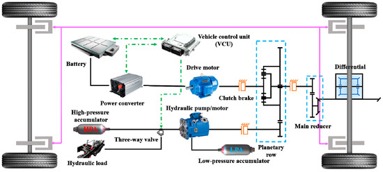
Figure 1.
The structure of the MSEH-HEV.
The main power of MSEH-HEV is provided by the power battery, and hydraulic energy, which is the auxiliary power, is converted from braking energy or electric energy. The planetary gear plays the role of a power shunt and torque coupling. The conversion and coupling between the three energies are based on the speed. When the vehicle works at high speed, it is mainly driven by electric power. At low driving speed, the vehicle is driven independently by hydraulic power or by the auxiliary electric power. In contrast, if the initial braking speed is high, the vehicle is braked by electric power. The braking energy will be converted into electrical energy and stored in the power battery. If the braking speed is low, the vehicle is braked by hydraulic energy. The HPA will store the hydraulic energy converted from the inertia energy. If the braking intensity is too high, the vehicle will be braked by hydraulic and electric power simultaneously. At this moment, the braking energy will be transformed into electric and hydraulic energy, and they will be stored in the battery and HPA, respectively. Moreover, when the pressure in the HPA is low, and the electrical power can provide more power than is required for the current operating conditions, the electrical system can convert part of the electrical energy into hydraulic energy and store it in the HPA.
2.2. Operating Modes of the MSEH-HEV
The operating modes of the MSEH-HEV can be divided into six types, as shown in Figure 2.
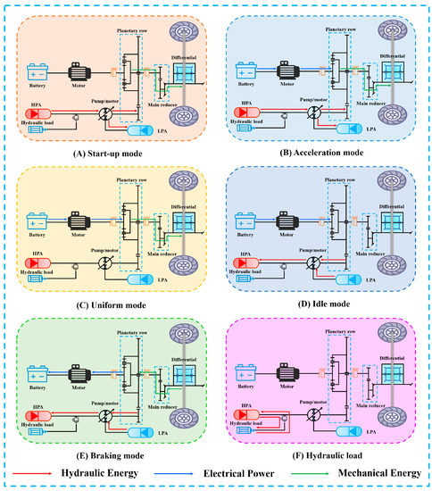
Figure 2.
The operating modes of the MSEH-HEV.
- Start-up mode: The torque required for starting the vehicle is large. Therefore, only hydraulic energy drives the vehicle when it is started. At this point, the high-pressure oil in the HPA flows into the LPA, so that the hydraulic pump/motor works in the motor state and converts hydraulic energy into mechanical energy to start the vehicle up to the speed threshold.
- Acceleration mode: When the vehicle starts up to the speed threshold, it enters the acceleration mode. The electric power begins to intervene. The electric power and hydraulic power are torque superposed through the planetary row to drive the vehicle to a higher speed.
- Uniform mode: With the increase in speed, the hydraulic power is switched off when the speed reaches a certain threshold, and the vehicle enters the uniform speed stage. In this case, the electric energy alone drives the vehicle at a constant speed, with the motor operating in the high-efficiency zone.
- Idle mode: In this mode, the electric energy is transformed into hydraulic energy. The hydraulic oil in the LPA is pumped into HPA to store the energy for vehicle starting or operating conditions requiring instantaneous high torque.
- Braking mode: If the speed is high, and the braking intensity is low, the drive motor is used as a generator. The braking energy is converted into electrical energy and stored in the power battery. If the speed and the braking intensity are low, the hydraulic pump/motor is used as a hydraulic pump. This enables the recovery of braking energy to hydraulic energy. If the braking intensity is high, the braking energy is transformed to electrical energy and hydraulic energy. Simultaneously, this will charge the power battery and fill the HPA with oil. In case of emergency braking, the mechanical brake is used, and the ABS takes over.
In addition, the system can be connected to the hydraulic load according to the needs of the actual situation, such as the hydraulic lifting system of the freight car. When sufficient energy is stored in the HPA, it can be connected to a hydraulic load and use hydraulic energy to drive the hydraulic load. When the hydraulic load is returned, the inertial energy of the system can also be converted into hydraulic energy to be charged back to the HPA. Of course, the hydraulic load requires a corresponding booster device. This further increases the usefulness of the system.
The electric vehicle equipped with the above system can be named the master-slave electro-hydraulic hybrid electric vehicle (MSEH-HEV).
3. Powertrain Parameters Matching
The complexity of matching vehicle parameters makes it one of the most important research problems in the study of vehicle dynamics and economy. In this section, the relevant parameters of the MSEH-HEV powertrain are matched, so that the key components can work as well as possible.
3.1. Vehicle Parameters and Performance Indicators
This paper is based on a light electric van as a prototype. Table 1 lists the main parameters of the MSEH-HEV.

Table 1.
Main parameters of the MSEH-HEV.
According to the relevant national requirements for HEVs, the parameters of performance on which this paper is based are displayed in Table 2.

Table 2.
Vehicle performance indicators.
3.2. Vehicle Dynamics Model
The total resistance ΣFt of a car driving on a flat road is generally composed of four parts, which are rolling resistance Ff, grade resistance Fi, acceleration resistance Fj and air resistance Fw. The formula for calculating the total resistance during driving is
3.3. Electric Power Parameter Matching
3.3.1. Motor
The MSEH-HEV is essentially an EV, and the electric drive system is the core of the pure electric vehicle. Therefore, we start with the selection and parameter matching of the drive motor. Good speed regulation characteristics, high efficiency and compact structure are the characteristics of the permanent magnet synchronous motor. It can meet the requirements of MSEH-HEVs. Therefore, this paper chooses the permanent magnet synchronous motor as the drive motor [33].
- Motor power
Determined by the maximum speed
where P1 is the power demand when driving uniformly at the highest speed; m is the total mass of the vehicle; g is the acceleration of gravity; f is the rolling resistance coefficient; u1 is the maximum vehicle speed; CD is the air resistance coefficient; A is the windward area.
Determined by the maximum climb
where αmax is the maximum climbing angle, taken as 17°; u2 is the maximum climbing ground steady speed.
Determined by acceleration time
where u3 is the final speed of the vehicle; t is the acceleration time of the vehicle; x is the fitting factor; dt is the iteration step of the design process.
The peak power Pmax of the EV drive motor should meet the requirements of all three operating conditions at the same time:
In addition, about 10% power shall be reserved to charge the battery pack and meet other losses, such as the air conditioning system, entertainment system and lighting system.
The rated power Pe is expressed as
where λ is the overload factor.
- Motor speed
In view of the cost of light goods vehicles, the peak speed of the drive motor should not be higher than 6000 r/min. Thus, the rated speed is 3000 r/min, and the peak speed is 6000 r/min.
3.3.2. Power Battery
Lithium iron phosphate batteries have received a lot of attention in recent years due to their high specific energy, high specific power, long cycle life and good safety features [34,35]. Therefore, we choose them as the storage unit for electrical energy in this paper.
- Battery pack voltage level determination
According to the principle, the voltage level of the battery pack must match the operating voltage range of the electric motor (250~420 V). Based on meeting the requirements of the normal operation of vehicles, the battery pack voltage should have a certain margin.
- Battery pack capacity determination
The capacity of the battery pack must meet the requirements of the vehicle range, so this paper adopts the isokinetic method to calculate it. The power required for the vehicle to travel at a constant speed uele in the electric mode is
The energy required to travel a certain distance S over an equal distance is
where Pele for the car is equal to the form of power required; η for the motor and mechanical system total efficiency; Wroad for the vehicle driving mileage S required energy; uele for the car is equal to the driving speed; S for the EV to the pure electric mode of driving mileage design requirements.
The battery storage energy required for EVs is
where WB indicates the actual energy; UB indicates the average working voltage; CB indicates the capacity; ηDOD indicates the depth of discharge.
The battery storage energy required for EVs is
3.4. Hydraulic Power Parameter Matching
3.4.1. Hydraulic Pump/Motor
The HP/M is an extraordinarily vital component of the MSEH-HEV. It is not only involved in the start-up, acceleration and climbing of the vehicle under heavy load conditions but also in the energy recovery during braking. To adapt the system to frequent changes in working conditions and to improve the efficiency of energy recovery, this paper selects a piston HP/M that can work stably for a long time in both pump and motor operating conditions [36,37].
- Maximum power of the HP/M
Calculation of power parameters based on acceleration requirements at vehicle starting
where Pmaxa is the maximum power in the hydraulic energy alone drive mode; umaxa is the maximum speed in the hydraulic energy alone drive mode; ηh is the transmission efficiency of the hydraulic system.
- Maximum torque of the HP/M
The maximum torque Tp of the HP/M can be expressed as
where V is the displacement of the HP/M; p is the working pressure of the HP/M.
3.4.2. Hydraulic Accumulator
The hydraulic accumulator is a key element of the MSEH-HEV [38]. In this paper, an airbag accumulator is selected as the hydraulic energy storage element. The airbag accumulator has two main important parameters: the working pressure p and the working volume V. The working pressure of the accumulator affects the braking performance of the hydraulic regenerative braking system, and the working volume of the accumulator affects the braking energy recovery capacity of the hydraulic regenerative braking system. Both parameters satisfy Boyle’s law:
where p0 is the accumulator inflation pressure; V0 is the accumulator inflation volume; p1 is the minimum working pressure; V1 is the gas volume when the pressure is p1; p2 is the highest working pressure; V2 is the gas volume when the pressure is p2; n is the multivariable index.
The formula for calculating the minimum working pressure p1 is
where Va is the displacement of the HP/M; umaxa is the maximum speed of the hydraulic energy alone drive mode; ib is the torque coupling speed ratio; i0 is the drive axle main reduction ratio.
The p2 is not only related to the life of the accumulator but also to the power consumption. Consequently, the selection of p2 is particularly important. The control condition of the maximum working pressure is p2 ≤ 3p1.
In the research, the accumulator is the auxiliary energy source. So, when matching the inflation pressure p0, the minimum capacity of the accumulator should be considered first. The calculation formula is
When the MSEH-HEV is braking for energy recovery, the energy balance equation of the vehicle is
where u4 and u5 are the speed of the vehicle at moments t4 and t5; E1 represents the energy lost, E2 represents the energy recovered; δ is the rotating mass conversion factor; s is the braking displacement; a is the deceleration.
Combining the above formulae, we can obtain
The inflation volume of the hydraulic accumulator is
The effective working volume Vx is the change in gas volume during the change from p1 to p2 in the accumulator. The above formula can be obtained as follows:
The LPA mainly plays the role of oil replenishment, so the effective volume of the high-pressure accumulator is its oil replenishment volume. In addition, in order to match the initial volume energy of the LPA with that of the HPA, the selection conditions of the pre-charging pressure and the minimum working pressure of the LPA are: P0* = P1* = P0 = P1. According to the empirical formula
3.5. Planetary Row Parameter Matching
The entire structure consists of the sun gear, planet gear, planet carrier and ring gear. In this system, the input shaft is connected to the sun gear; the planet carrier is related to the output shaft, and the gears on the outer edge of the ring gear engage with the hydraulic energy direct gear. In the planetary row structure of this paper, all three components, the sun wheel, the planetary frame and the gear, are capable of rotation. This is a differential planetary row mechanism with two degrees of freedom, which has both variable speed and differential characteristics. The arrangement of the planetary row enables the combination and separation of energy, adapting to different energy transmission situations in a wide range of operating conditions [39,40].
The speed ratio between the ring and the sun gear is usually taken as the basic characteristic parameter of the planetary row:
where kp is the characteristic parameter of the planetary row; Z2 is the teeth number of the ring gear; Z1 is the teeth number of the sun gear.
The speed relationship between the sun gear, ring gear and planet carrier
where ω1 is the angular speed of the sun gear, ω2 is the angular speed of the ring gear, and ω3 is the angular speed of the planet carrier.
The torque relationship between the sun gear, planet carrier and ring gear
where T1 is the sun gear torque, T2 is the ring gear torque, and T3 is the planet carrier torque.
According to the above, the parameters of each element in MSEH-HDS are shown in Table 3.

Table 3.
Parameters of each element in MSEH-HDS.
4. Rule-Based Control Strategy
Control strategies play a crucial role in HEVs. A well-designed control strategy enables the matching of powertrain parameters and highlights the advantages of the MSEH-HEV.
At present, the control strategies applied to HEVs mainly include the rule-based control strategy, transient optimal control strategy and global optimal control strategy. The rule-based control strategy is particularly practical and easy to control. It is highly suitable for the control of multi-mode switching in hybrid power systems. It relies heavily on theoretical analysis and existing experience to set parameter values [41,42]. Hybrid systems operate in multiple modes, each independent of the other. Adaptive control can be realized by decomposing the working mode of the power system according to the driving environment of the vehicle.
The research designs a logical threshold energy management strategy based on the rule-based control strategy. Vehicle speed (v) has a significant effect on the energy consumption rate. Therefore, in this paper, the desired vehicle speed is used as the control input signal to timely monitor the SOC, pressure difference (pre) and energy storage conditions. When the total weight and the volume of the acceleration are certain, the acceleration capability, speed following characteristics and energy loss of the vehicle, are all related to the threshold. Therefore, in this paper, the v and pre between the HPA and LPA are determined as the thresholds of mode switching of the control strategy. Figure 3 displays a flow chart of the conversion between different modes of MSEH-HEV.
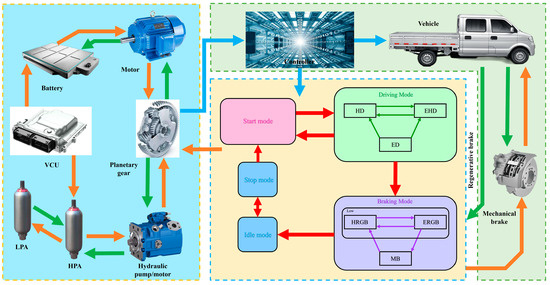
Figure 3.
The flow chart of the conversion between different modes of MSEH-HEV.
The state of charge of the HPA (HaccSOC) can be expressed as
where pa is the current pressure; pb is the gas pre-charge pressure; pamax is the maximum pressure.
Figure 4 shows the concrete logical diagram of mode switching. In addition, the specific description of the rules of the control strategy is as follows:
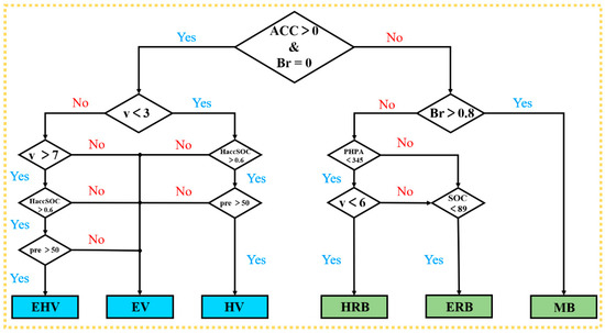
Figure 4.
Logical control policy diagram.
(1) When the accelerator pedal is depressed, the acceleration signal (Acc) is greater than 0, the vehicle enters the driving mode. Simultaneously, the sensor detects the magnitude of the v, HaccSOC and pre.
If v < 3 m/s, HaccSOC > 0.6, and pre > 50, the vehicle enters the HD mode. If 3 m/s ≤ v ≤ 7 m/s, or HaccSOC ≤ 0.6, or pre ≤ 50, the vehicle enters the ED mode. If v > 7 m/s, HaccSOC > 0.6, and pre > 50, the vehicle enters the EHD mode.
(2) When the brake pedal is depressed, the brake signal (Br) is greater than 0, the vehicle enters the braking mode. Meanwhile, the sensor detects the size of the vehicle speed v, HaccSOC, PHPA, pre and judges the size of the braking strength Br.
If Br > 0.8, v ≥ 6, and SOC ≥ 89, the vehicle goes into the MB mode. If Br ≤ 0.8, PHPA < 345, and v < 6, the vehicle goes into the HRB mode. If Br ≤ 0.8, v ≥ 6, and SOC < 89, the vehicle goes into the ERB mode.
5. Simulation Validation and Results Analysis
This section introduces the process of building the vehicle simulation model. In addition, the accuracy of parameter matching and control strategy is verified in this section through joint simulation. Finally, this section analyzes the simulation results in detail.
5.1. Simulation Model
Based on the above research and analysis, the simulation model of MESH-HEV is established. The establishment of the vehicle model requires multi domain cooperation. This paper builds the vehicle model in AMESim. The control strategy of the MSEH-HEV is built in Simulink. After that, this research creates a joint simulation interface in AMESim to realize joint simulation with Simulink [43]. Figure 5 shows the simulation model of the vehicle.
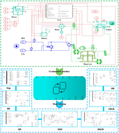
Figure 5.
The MSEH-HEV mode in AMEsim and Simulink.
The ECE + EUDC is a test method for testing the fuel consumption of vehicles in Europe. It can be divided into two parts. The first part consists of four conventional urban road driving conditions. The second part is an additional suburban driving cycle. Its total length is 1220 s. Table 4 describes the other details of the ECE + EUDC cycle. The driving cycle can well simulate the road conditions between the city and the suburb. Therefore, this paper uses ECE + EUDC for simulation verification of MSEH-HEV.

Table 4.
Cycle parameters of the ECE + EUDC.
5.2. Simulation Results and Analysis
Figure 6 displays the vehicle speed curves. The real vehicle speed roughly coincides with the control speed, indicating a high level of vehicle path tracking accuracy. The acceleration time when the vehicle is started is less than the control speed. In addition, the vehicle braking time to 0 km/h is advanced by 4.69 s. The simulation results prove that the control strategy of the MSEH-HEV can meet the expectations of real driving conditions with a certain degree of reliability.
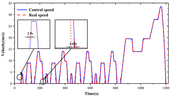
Figure 6.
Speed curves.
Figure 7A,B show the change of accumulator pressure and swashplate signals, respectively. The two are constantly changing throughout the operation of the vehicle. When the signal is positive, the hydraulic energy is liberated. When the swashplate signal is negative, the hydraulic energy is restored.
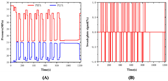
Figure 7.
(A) Accumulator pressure change curve; (B) Swashplate signals change curve.
During a cycle, the hydraulic accumulator pressure can vary continuously with the speed of the vehicle, as proven in Figure 8. If the vehicle speed increases, the PHPA pressure reduces, and the PLPA rises. If the speed decreases, the PHPA pressure rises, and the PLPA reduces. The results show that hydraulic energy can work adequately during vehicle operation and that the effective liberation and recovery of hydraulic energy proves the reliability of the hydraulic system in the MSEH-HEV.
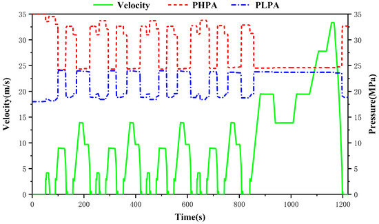
Figure 8.
The curves for the PHPA and the PLPA.
Figure 9 expresses the motor torque characteristics of the two vehicles. The MSEH-HEV has a significantly lower motor torque compared to the AMESim certified EV, especially the peak torque at start-up. Moreover, the motor rotates backward when the vehicle is in the braking condition, and the motor torque determines the energy recovery efficiency at this time. In the figure, the torque of the MSEH-HEV is significantly greater than that of the EV when the energy is recovered by braking. It is proved that the electrical energy recovery rate of the MSEH-HEV has an obvious increase. However, it is worth noting that the motor torque is sometimes unstable, as pointed by the black arrow. Through the analysis of the simulation results, it is thus clear that this is a phenomenon caused by the vehicle mode switching. It is necessary to be optimized in the subsequent work to improve the stability of the motor torque.
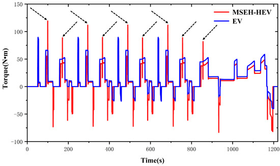
Figure 9.
Motor torque curves.
Battery consumption rates are often used as an index to appraise the economy of EVs. The calculation formula is
where σbattery is the battery consumption rate, Crated is the rated capacity of the battery, CEV is the remaining battery capacity of the EV, and C1 is the remaining battery capacity of the MSEH-HEV.
Figure 10 demonstrates a comparison of the battery SOC for the MSEH-HEV and the EV. Both have an initial battery SOC of 90%. As can be seen from the figure, after a complete ECE + EUDC cycle, the battery SOC of the MSEH-HEV is 84.2070%, while that of the EV is 83.3925. Therefore, compared with electric vehicles, the battery consumption rate of the MSEH-HEV is reduced by 15%. This illustrates that the battery pack works well under the ECE + EUDC cycle and that the coordination between the electromotor, the hydraulic pump/motor and the battery pack is good. It meets the operating requirements during vehicle operation.
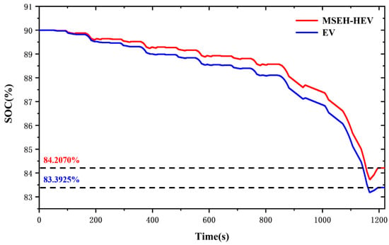
Figure 10.
Battery SOC curves.
6. Fuzzy Optimization
In order to further improve the motor torque characteristics, we will optimize the control strategy in this section. Because the control strategy in this paper is built in Simulink, the fuzzy toolbox in Simulink will be used for optimization [44].
6.1. Fuzzy Controller Design
The fuzzy controller designed in this paper contains two inputs and one output. The two inputs are v and pre. The proportional factor of the motor torque k is the output. The MSEH-HEV allows the motor torque to be adjusted in real time during driving according to k. In fuzzy control, the variable size is described in language. This paper chooses large, small, positive, negative and zero to describe the state of variables in the fuzzy controller. There are five words in total, including negative big (NB), negative small (NS), zero (ZO), positive small (PS) and positive big (PB). The fuzzy subset of v, pre and k is {NB, NS, ZO, PS, PB}. In addition, the fuzzy domain of v is [0, 35], that of pre is [0, 350], and [0, 1] is the fuzzy domain of k.
In this paper, the membership function of three variables is designed, respectively, in the fuzzy controller, as shown in Figure 11. The fuzzy rules should follow the principle: in a certain speed range, the larger the pre, the smaller the k. The fuzzy control rules established based on the above are described in Table 5.
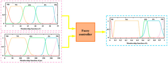
Figure 11.
Membership function of input and output variables.

Table 5.
Fuzzy control rules.
6.2. Optimization Results and Analysis
To ensure the credibility of the fuzzy optimization results, this paper continues to select the ECE + EUDC cycle for verification.
Figure 12 expresses the speed curve of MESH-HEV under fuzzy control, which highly coincides with the speed curve under the rule-based control. It proves that the MSEH-HEV model can simulate normally. Moreover, the velocity curve obtained by simulation proves that the fuzzy control strategy is reasonable.
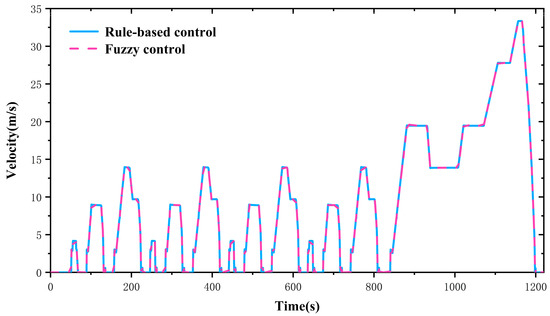
Figure 12.
Fuzzy optimization analysis: speed curve.
Figure 13 displays the changes in motor torque characteristics. It can clearly be seen that the motor peak torque is significantly improved after fuzzy optimization of the control strategy. This will effectively reduce the impact caused by excessive torque during driving.
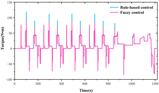
Figure 13.
Fuzzy optimization analysis: torque curve.
Figure 14 demonstrates the comparison of the battery SOC. It can be seen from the figure that the battery SOC is almost the same under the two control strategies. Actually, the battery SOC under the fuzzy control strategy is 84.2073%, and that with rule-based control strategy is 84.2070%. The optimized control strategy has a slight improvement on the battery SOC.
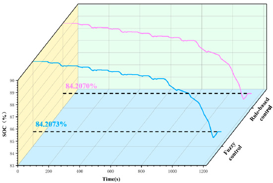
Figure 14.
Fuzzy optimization analysis: battery SOC curve.
The simulation results certify that the fuzzy control strategy not only ensures the battery SOC but also greatly reduces the motor peak torque. The comprehensive performance of the vehicle is further improved.
7. Conclusions
The paper proposed a MSEH-HEV to improve the battery SOC, develop the dynamic performance during frequent start/stop and increase the driving range. By comparison with the existing cases of EHVs, the paper deeply analyzed the shortcomings of conventional EVs and introduced in detail the principle and operating modes of the MSEH-HEV.
According to the different driving conditions of the vehicle, this paper summarized six operating modes and analyzed the energy transmission routes and manners of operation for each mode. The research established mathematical models for the mechanical, electrical and hydraulic energy of the MSEH-HEV and parametrically matched the key components of the transmission system. In addition, a ruled-based control strategy was established to realize the operating mode switching and energy distribution. Based on the ECE + EUDC cycle, the research used AMESim/Simulink co-simulation platform to simulate the speed following characteristics, electric power, HPA pressure and battery SOC of the MSEH-HEV. In addition, to further improve the stability of the motor torque, the fuzzy optimization was carried out based on the rule-based control strategy.
The dynamic simulation results showed that the battery SOC of MSEH-HEV was 15% lower than that of the EV, which verified its feasibility and effectiveness. Compared to conventional EVs, the MSEH-HEV could achieve a multi-source energy drive. It improved the vehicle’s dynamic performance, reduced the peak torque of the driving motor and decreased the battery energy consumption. Compared to conventional electro-hydraulic hybrid vehicles, the MSEH-HEV used the planetary row to achieve coupling between different energy sources, decreasing the complexity of the system and thereby reducing the vehicle mass.
At present, most of the research works on the electro-hydraulic hybrid system are concerned with heavy-duty commercial vehicles, rather than a system based on small vehicles. This paper fills the gap in this research direction. Moreover, the MSEH-HEV has a better economy and dynamic. This paper has essential reference significance and value for the development and popularization of the electro-hydraulic hybrid electric vehicle.
There is still plenty of work to be done in the development of electro-hydraulic hybrid electric vehicles. Firstly, the methods of engineering optimization are numerous. In the subsequent work, we should study and innovate more the existing optimization methods to achieve a better optimization effect. Moreover, there have been a growing number of research papers on hydraulic hybrid power in recent years, but most of them only focus on the simulation stage. In the future, the research on the hydraulic hybrid electric vehicle should be carried out in a real vehicle experiment.
Author Contributions
Conceptualization, Q.J. and H.Z.; methodology, Q.J.; software, Q.J.; validation, Q.J. and H.Z.; formal analysis, J.Y.; investigation, Y.Z. and J.Y.; resources, H.Z.; data curation, H.Z.; writing—original draft preparation, Q.J.; writing—review and editing, J.W.; visualization, Y.Z. and J.W.; supervision, J.Y.; project administration, Y.Z.; funding acquisition, H.Z. All authors have read and agreed to the published version of the manuscript.
Funding
This research was funded by the National Natural Science Foundation of China, grant number 52075278, and the Municipal Livelihood Science and Technology Project of Qingdao, grant number 19-6-1-92-nsh.
Institutional Review Board Statement
Not applicable.
Informed Consent Statement
Not applicable.
Data Availability Statement
Not applicable.
Conflicts of Interest
The authors declare no conflict of interest.
References
- Dong, F.; Liu, Y. Policy evolution and effect evaluation of new-energy vehicle industry in China. Resour. Policy 2020, 67, 101655. [Google Scholar] [CrossRef]
- Yuan, X.; Liu, X.; Zuo, J. The development of new energy vehicles for a sustainable future: A review. Renew. Sustain. Energy Rev. 2015, 42, 298–305. [Google Scholar] [CrossRef]
- Fallahpour, A.; Wong, K.Y.; Rajoo, S.; Fathollahi-Fard, A.M.; Antucheviciene, J.; Nayeri, S. An integrated approach for a sustainable supplier selection based on Industry 4.0 concept. Environ. Sci. Pollut. Res. 2021, 1–19. [Google Scholar] [CrossRef]
- Ghadami, N.; Gheibi, M.; Kian, Z.; Faramarz, M.G.; Naghedi, R.; Eftekhari, M.; Fathollahi-Fard, A.M.; Dulebenets, M.A.; Tian, G. Implementation of solar energy in smart cities using an integration of artificial neural network, photovoltaic system and classical Delphi methods. Sustain. Cities Soc. 2021, 74, 103149. [Google Scholar] [CrossRef]
- Tian, G.; Yuan, G.; Aleksandrov, A.; Zhang, T.; Li, Z.; Fathollahi-Fard, A.M.; Ivanov, M. Recycling of spent Lithium-ion Batteries: A comprehensive review for identification of main challenges and future research trends. Sustain. Energy Technol. Assess. 2022, 53, 102447. [Google Scholar] [CrossRef]
- Yu, H.; Dai, H.; Tian, G.; Wu, B.; Xie, Y.; Zhu, Y.; Zhang, T.; Fathollahi-Fard, A.M.; He, Q.; Tang, H. Key technology and application analysis of quick coding for recovery of retired energy vehicle battery. Renew. Sustain. Energy Rev. 2021, 135, 110129. [Google Scholar] [CrossRef]
- Tian, G.; Zhang, C.; Fathollahi-Fard, A.M.; Li, Z.; Zhang, C.; Jiang, Z. An Enhanced Social Engineering Optimizer for Solving an Energy-Efficient Disassembly Line Balancing Problem Based on Bucket Brigades and Cloud Theory. IEEE Trans. Ind. Inform. 2022, 1–11. [Google Scholar] [CrossRef]
- Itani, K.; De Bernardinis, A.; Khatir, Z.; Jammal, A. Comparison between two braking control methods integrating energy recovery for a two-wheel front driven electric vehicle. Energy Convers. Manag. 2016, 122, 330–343. [Google Scholar] [CrossRef]
- Verma, S.; Mishra, S.; Gaur, A.; Chowdhury, S.; Mohapatra, S.; Dwivedi, G.; Verma, P. A comprehensive review on energy storage in hybrid electric vehicle. J. Traffic Transp. Eng. Engl. Ed. 2021, 8, 621–637. [Google Scholar] [CrossRef]
- Tian, G.; Liu, Y.; Ke, H.; Chu, J. Energy evaluation method and its optimization models for process planning with stochastic characteristics: A case study in disassembly decision-making. Comput. Ind. Eng. 2012, 63, 553–563. [Google Scholar] [CrossRef]
- Wang, H.; Yang, W.; Chen, Y.; Wang, Y. Overview of hybrid electric vehicle trend. Proc. AIP Conf. Proc. 2018, 1995, 040160. [Google Scholar]
- Kim, Y.J.; Filipi, Z. Simulation study of a series hydraulic hybrid propulsion system for a light truck. SAE Trans. 2007, 116, 147–161. [Google Scholar]
- Hui, S.; Ji-Hai, J.; Xin, W. Torque control strategy for a parallel hydraulic hybrid vehicle. J. Terramechanics 2009, 46, 259–265. [Google Scholar] [CrossRef]
- Houyu, L.; Guirong, Z. Hybrid electric vehicle drive control. Proc. Environ. Sci. 2011, 10, 403–407. [Google Scholar] [CrossRef][Green Version]
- Yin, J.; Chen, X.B.; Shu, T.; Ning, G.B. A novel planetary gear hybrid powertrain. Proc. Appl. Mech. Mater. 2013, 278, 22–26. [Google Scholar] [CrossRef]
- Mantriota, G.; Reina, G. Dual-motor planetary transmission to improve efficiency in electric vehicles. Machines 2021, 9, 58. [Google Scholar] [CrossRef]
- Chen, J.-S. Energy efficiency comparison between hydraulic hybrid and hybrid electric vehicles. Energies 2015, 8, 4697–4723. [Google Scholar] [CrossRef]
- Pfeffer, A.; Glück, T.; Kemmetmüller, W.; Kugi, A. Mathematical modelling of a hydraulic accumulator for hydraulic hybrid drives. Math. Comput. Model. Dyn. Syst. 2016, 22, 397–411. [Google Scholar] [CrossRef]
- Hui, S.; Junqing, J. Research on the system configuration and energy control strategy for parallel hydraulic hybrid loader. Autom. Constr. 2010, 19, 213–220. [Google Scholar] [CrossRef]
- Zhou, S.; Walker, P.; Zhang, N. Parametric design and regenerative braking control of a parallel hydraulic hybrid vehicle. Mech. Mach. Theory 2020, 146, 103714. [Google Scholar] [CrossRef]
- Liu, X.; Ma, J.; Zhao, X.; Zhang, Y.; Zhang, K.; He, Y. Integrated component optimization and energy management for plug-in hybrid electric buses. Processes 2019, 7, 477. [Google Scholar] [CrossRef]
- Fathollahi-Fard, A.M.; Dulebenets, M.A.; Hajiaghaei–Keshteli, M.; Tavakkoli-Moghaddam, R.; Safaeian, M.; Mirzahosseinian, H. Two hybrid meta-heuristic algorithms for a dual-channel closed-loop supply chain network design problem in the tire industry under uncertainty. Adv. Eng. Inform. 2021, 50, 101418. [Google Scholar] [CrossRef]
- Ke, H.; Ma, J.; Tian, G. Hybrid multilevel programming with uncertain random parameters. J. Intell. Manuf. 2017, 28, 589–596. [Google Scholar] [CrossRef]
- Ke, H.; Liu, H.; Tian, G. An uncertain random programming model for project scheduling problem. Int. J. Intell. Syst. 2015, 30, 66–79. [Google Scholar] [CrossRef]
- Chen, G.; Liu, H. Design and energy utilization of electro-hydrostatic hydraulic hybrid system for battery bus. Proc. Inst. Mech. Eng. Part D J. Automob. Eng. 2021, 235, 759–772. [Google Scholar] [CrossRef]
- Hwang, H.-Y.; Lan, T.-S.; Chen, J.-S. Optimization and application for hydraulic electric hybrid vehicle. Energies 2020, 13, 322. [Google Scholar] [CrossRef]
- Meng, Z.; Zhang, H.; Yang, J.; Zhao, Q. Research on matching of power transmission system of electro-hydraulic hybrid electric vehicle. Proc. IOP Conf. Ser. Earth Environ. Sci. 2021, 632, 032007. [Google Scholar] [CrossRef]
- Fu, X.; Zhang, Q.; Tang, J.; Wang, C. Parameter matching optimization of a powertrain system of hybrid electric vehicles based on multi-objective optimization. Electronics 2019, 8, 875. [Google Scholar] [CrossRef]
- Mohamed, M.A.; Abdullah, H.M.; El-Meligy, M.A.; Sharaf, M.; Soliman, A.T.; Hajjiah, A. A novel fuzzy cloud stochastic framework for energy management of renewable microgrids based on maximum deployment of electric vehicles. Int. J. Electr. Power Energy Syst. 2021, 129, 106845. [Google Scholar] [CrossRef]
- Yang, J.; Zhang, T.; Zhang, H.; Hong, J.; Meng, Z. Research on the starting acceleration characteristics of a new mechanical–electric–hydraulic power coupling electric vehicle. Energies 2020, 13, 6279. [Google Scholar] [CrossRef]
- Hong, J.; Ma, F.; Xu, X.; Yang, J.; Zhang, H. A novel mechanical-electric-hydraulic power coupling electric vehicle considering different electrohydraulic distribution ratios. Energy Convers. Manag. 2021, 249, 114870. [Google Scholar] [CrossRef]
- Yang, J.; Zhang, T.; Hong, J.; Zhang, H.; Zhao, Q.; Meng, Z. Research on driving control strategy and Fuzzy logic optimization of a novel mechatronics-electro-hydraulic power coupling electric vehicle. Energy 2021, 233, 121221. [Google Scholar] [CrossRef]
- Li, L.; Liu, Y. Design and simulation of permanent magnet synchronous motor control system. Proc. AIP Conf. Proc. 2018, 1971, 040031. [Google Scholar] [CrossRef]
- Liao, X.; Yu, J.; Gao, L. Electrochemical study on lithium iron phosphate/hard carbon lithium-ion batteries. J. Solid State Electrochem. 2012, 16, 423–428. [Google Scholar] [CrossRef]
- Hong, J.; Wang, Z.; Ma, F.; Yang, J.; Xu, X.; Qu, C.; Zhang, J.; Shan, T.; Hou, Y.; Zhou, Y. Thermal runaway prognosis of battery systems using the modified multiscale entropy in real-world electric vehicles. IEEE Trans. Transp. Electrif. 2021, 7, 2269–2278. [Google Scholar] [CrossRef]
- Qu, J.; Ren, C.; Yang, Z.; Zhang, X. Parameters optimization method for variable displacement pump/motor and transmission of hydraulic braking energy regeneration system. In Proceedings of the 2009 International Forum on Computer Science-Technology and Applications, Chongqing, China, 25–27 December 2009; pp. 19–22. [Google Scholar]
- Breidi, F.; Garrity, J.; Lumkes, J. Design and testing of novel hydraulic pump/motors to improve the efficiency of agricultural equipment. Trans. ASABE 2017, 60, 1809–1817. [Google Scholar] [CrossRef]
- Mamèic, S.; Bogdevièius, M. Simulation of dynamic processes in hydraulic accumulators. Transport 2010, 25, 215–221. [Google Scholar] [CrossRef]
- Raghavan, M. The analysis of planetary gear trains. In Proceedings of the ASME 2006 International Design Engineering Technical Conferences and Computers and Information in Engineering Conference, Philadelphia, PA, USA, 10–13 September 2006. [Google Scholar]
- Wang, C. The effect of planetary gear/star gear on the transmission efficiency of closed differential double helical gear train. Proc. Inst. Mech. Eng. Part C J. Mech. Eng. Sci. 2020, 234, 4215–4223. [Google Scholar] [CrossRef]
- Fan, H.; Peng, J.; He, H. Rule-based plug-in hybrid school bus energy management control strategy simulation. In Proceedings of the 2015 10th Asian Control Conference (ASCC), Kota Kinabalu, Malaysia, 31 May–3 June 2015; pp. 1–6. [Google Scholar]
- Fathollahi-Fard, A.M.; Hajiaghaei-Keshteli, M.; Tavakkoli-Moghaddam, R. A bi-objective green home health care routing problem. J. Clean. Prod. 2018, 200, 423–443. [Google Scholar] [CrossRef]
- Lu, W.C.; Niu, G.S.; Long, C.; Wang, R.C. Study on the Electro-Hydraulic Power Steering System Based on AMESim and Simulink. Proc. Adv. Mater. Res. 2012, 422, 610–613. [Google Scholar] [CrossRef]
- Tian, G.; Chu, J.; Liu, Y.; Ke, H.; Zhao, X.; Xu, G. Expected energy analysis for industrial process planning problem with fuzzy time parameters. Comput. Chem. Eng. 2011, 35, 2905–2912. [Google Scholar] [CrossRef]
Publisher’s Note: MDPI stays neutral with regard to jurisdictional claims in published maps and institutional affiliations. |
© 2022 by the authors. Licensee MDPI, Basel, Switzerland. This article is an open access article distributed under the terms and conditions of the Creative Commons Attribution (CC BY) license (https://creativecommons.org/licenses/by/4.0/).