1. Introduction
With the continuous development of renewable energy [
1,
2], the proportion of wind power generation, photovoltaic power generation and other power generation technologies in the power grid continues to increase. New energy power generation technologies can not only replace the power grid to provide a temporary power supply for local loads, but also have the advantages of good power quality and environmental friendliness. They can provide voltage and frequency support for the power grid [
3,
4], while most of them are connected to the large power grid through the converter interface.
At present, the control mode of converters can be divided into two types according to the synchronizing type, which are grid-following converters and grid-forming converters, respectively. Among them, the grid-following converter is a grid-synchronizing control based on voltage control [
5], which measures or calculates the voltage frequency and phase at the common coupling point through a phase-locked loop (PLL), and uses the detected phase for vector current control or direct power control, so as to adjust the output active and reactive power of the converter. The control structure assumes that each control loop can complete its own control objectives independently, and there is no coupling between them. However, when the power grid is weak, the dynamic coupling of each control loop of the grid-following converter is strong, which easily leads to system instability [
6].
Unlike the grid following converter, which is prone to small interference-synchronizing oscillation instability under the weak current network, the grid-forming converter can be applicable to both strong and weak power grids and provide high-quality electric energy for the grid or load [
7]. As a voltage source, it generates the phase angle and amplitude of the output voltage through the power control loop during normal operation, so as to maintain synchronization with the grid. Thus, it does not need to use a phase-locked loop for grid synchronization [
8]. There are three typical schemes for power control of grid-forming converters, which are power-synchronizing control, droop control and virtual synchronizing machine control. Among them, the droop control has many advantages because of its simple structure, easy control and low cost [
9]. Converters with a droop-control strategy can be widely used in practical engineering projects as a voltage source.
Different from the traditional synchronizing machine power supply, the droop-controlled converter power supply does not contain a mechanical rotor [
10]. The response speed is faster, but it lacks the corresponding moment of inertia and damping characteristics during the operation. And its robustness is poor, so there may be some risks of synchronizing instability under disturbances [
11]. In order to ensure the stable operation of the power system, the synchronizing stability analysis under disturbances is particularly critical.
The disturbances can be divided into static disturbance (small disturbance) and transient disturbance (large disturbance) in consideration of different degrees. The stability under small disturbances can be linearized in the time domain or the complex frequency domain, and a theoretical system has been preliminarily formed [
12]. However, the synchronizing stability of large disturbances can only be analyzed in the time domain, which is difficult to linearize, and the analysis method is complex, so it is a hot topic of current academic research. And under different working conditions, due to the different feeder lengths, there is a deviation in the line impedances between the converter and the power grid, while the influence of different line impedances on the synchronizing stability of the system is also different [
13,
14]; this needs to be analyzed in detail.
Therefore, with regard to the synchronizing stability of converters under large disturbances, the literature [
15,
16] revealed the relationship between the synchronizing stability of the converter and the power angle stability of the traditional synchronous generator, and studied the instability mechanism of converters. But it only made a general summary, and did not analyze the impact of a specific large disturbance on the synchronizing stability. The literature [
17] analyzed the synchronizing stability of the voltage source converter under the fault of a power grid sag, and deduced the critical condition of the converter’s transient synchronizing instability under the grid voltage sag through phase portrait analysis. The literature also mentioned that the output current amplitude of the converter would increase after the fault, but it did not consider the negative impact of excessive current on the converter. Therefore, the analysis was not comprehensive. The literature [
18,
19] proposed that large disturbances will make the converters produce large impulse currents. And due to the weak endurance of power electronic devices, it is necessary to set the current limitation in droop control to protect power electronic devices from damage during gird faults, but it did not propose a specific current limitation strategy. The literature [
20] proposed a current reference-limiting technique method. By freezing the virtual angular speed, the converter current will be strictly limited, and the transient stability can be enhanced. However, using this method cannot ensure that a converter recovers voltage controllability after fault clearance. The literature [
21] analyzed the influence of different degrees of disturbance on the power angle characteristics of the converter in detail, and proposed a
d-axis priority-based current amplitude limitation strategy. Compared with the current limiting method in the literature [
20], the
d-axis priority-based current amplitude limitation strategy responds faster, and is more suitable for this article. The literature [
22] analyzed the synchronizing stability of the converter after entering the current saturation mode during gird faults. However, it only analyzed the situation in which the system directly entered the current saturation mode after a fault, and did not consider the situation in which the system switched between current saturation mode and unsaturated mode, which made the analysis process incomplete. And this kind of situation is related to the line impedance.
Therefore, in order to analyze the synchronizing stability of the droop-controlled converter under large disturbances, the synchronizing dynamic model of the droop-controlled converter is established in this article first. And then, the change in output current at the moment of the fault is analyzed by a vector diagram. After that, the influence of different line impedances on the synchronizing stability of converters during different degrees of grid voltage sags is precisely analyzed. The analysis results are given in the form of power angle curves, and the correctness of the analysis is verified by simulation. The main contributions of this paper are summarized as follows:
- (a)
The transient process of converters switching from voltage source to current source under voltage sags is theoretically explained; that is, the sudden increase in the current amplitude will make the current limitation module respond under voltage sags, so that the amplitude will be limited. This transient switching process can be applied to practical projects to prevent the power electronic equipment in the converters from being damaged due to overcurrent.
- (b)
The influence of different voltage sags on the synchronizing stability of the system is studied considering different line impedances. It paves the way for the follow-up research on the synchronizing stability of multi-converters and the corresponding control methods to improve the synchronizing stability.
The rest of this paper is organized as follows. In
Section 2, the investigated system structure is given. In
Section 3, the three-phase voltage source converter model based on droop control is developed. Based on the developed model, the mechanism of transient synchronizing stability is revealed in
Section 4. Then, simulation and simulation results are discussed in
Section 5. Finally, conclusions are drawn in
Section 6.
2. System Structure
The basic control principle of droop control is to simulate the frequency and voltage regulation characteristics of a synchronizing generator, so as to achieve more convenient and effective control of the micro power supply and realize the average distribution of active power and reactive power between parallel converters.
The topology of the three-phase voltage source converter based on droop control is shown in
Figure 1. The converter adopts vector control in a rotating coordinate system, and the control structure can be divided into three layers.
The outermost layer is the P-ω and QV droop control loop. The P-ω droop control obtains the angular frequency reference value by combining the output active power and the rated angular frequency. The QV droop control obtains the voltage reference value by combining the output reactive power and the rated voltage, which is used for parallel power sharing among multiple converters. The expression of droop control is shown in Formula (1):
where V
0 is the voltage-setting value of the reactive voltage droop control; P
ref and Q
ref are the given values of the active power and reactive power of the converter, respectively; P
E and Q
E are the output active power and reactive power of the converter, respectively; K
P and K
q are active frequency and reactive voltage droop control coefficients, respectively; ω is the reference value of the angular frequency of the converter; ω
0 is the angular frequency of the infinite grid as well as the rated angular frequency.
The dq-axis voltage control loop in the middle layer is used to adjust the output voltage to follow the command value. It detects the deviation between the dq-axis voltage feedback and the command value, adjusts the output current command through the PI controller, drives the voltage feedback to follow the voltage command, prevents overcurrent, and often limits the amplitude.
The internal dq-axis current control is used to adjust the output current to follow the command value. It detects the deviation between the dq-axis current feedback and the command value, adjusts the output voltage through the PI controller, drives the current feedback to follow the current command, and generates a voltage modulation wave, which drives the semiconductor switch through the PWM module.
It can be seen from
Figure 1 that after the output current of the converter changes during a gird fault, the current inner loop first responds, causing the output voltage of the converter to change, and then causing the voltage outer loop response. Therefore, in general, the response speed of the current loop control is faster than that of the voltage loop control. Because a low-pass filter is often added to the power droop control loop, the response speed of the power droop control loop is the slowest and the time is the longest.
Due to the weak overcurrent tolerance of the power electronic equipment, in order to prevent excessive current under large disturbances such as grid fault, the current limitation control can be used between the voltage control loop and the current control loop. And the current command output by the voltage control loop is often designed to limit the amplitude. The
dq-axis current command before limitation is controlled and adjusted by the voltage control loop, and the
dq-axis current command after limitation is determined by the limited amplitude. A droop-controlled converter often uses the
d-axis priority based on a current limitation strategy similar to that in the literature [
19], which is described in Formula (2).
The current saturation mode is defined as the case that the converter output current amplitude reaches I
max and is limited by the current limitation strategy, while the current unsaturated mode is defined as the case that the converter output current amplitude is less than I
max.
where the symbols of i
d*, i
q* are the same as those of i
d**, i
q**, respectively; I
max is the maximum allowable current amplitude, and:
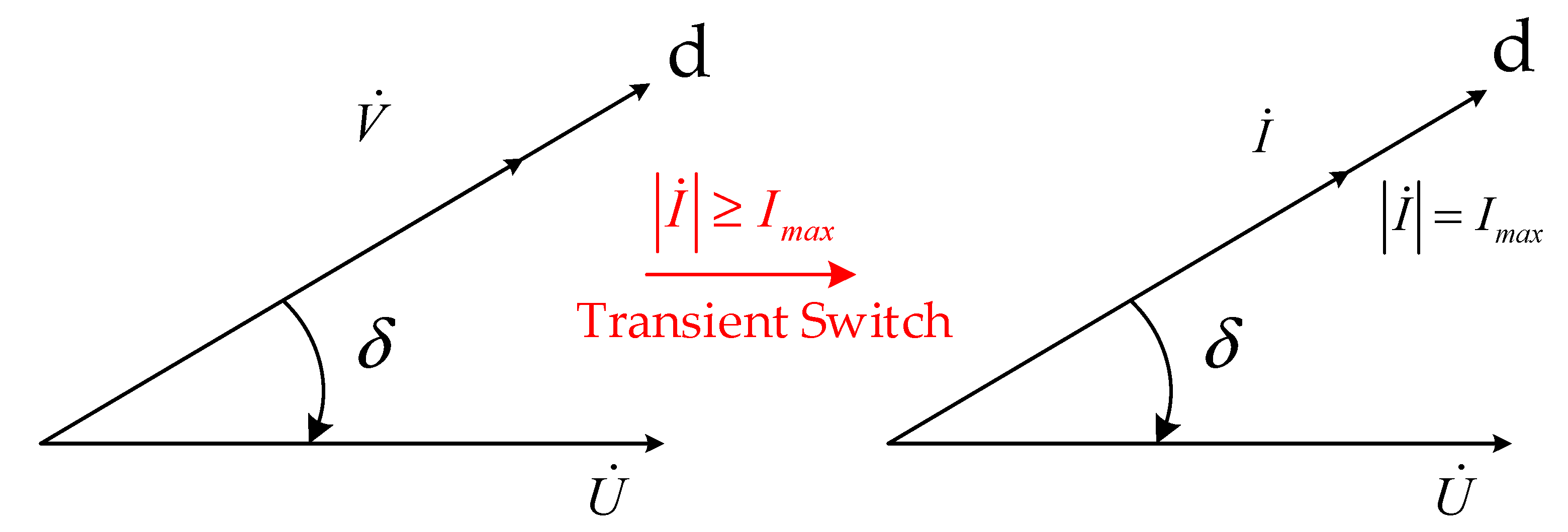
According to Formula (2), under large disturbances, the output current amplitude of the converter increases sharply. When it increases to Imax, the current limitation module would respond, which makes the output current quickly locate at the d-axis, and the amplitude remains Imax. The converter power supply is switched from voltage source to current source.
To sum up, due to the current command limitation strategy, the droop-controlled converter has a voltage source/current source transient-mode switching process. When the system works normally, the converter can be equivalent to a controlled voltage source with series output impedance. Under large disturbances, the converter may enter current saturation mode during gird fault, causing the converter to switch from voltage source to current source. This kind of transient mode switching between voltage source and current source makes the analysis of the synchronizing stability of the converter complex.
3. Analysis Model for Synchronizing Stability
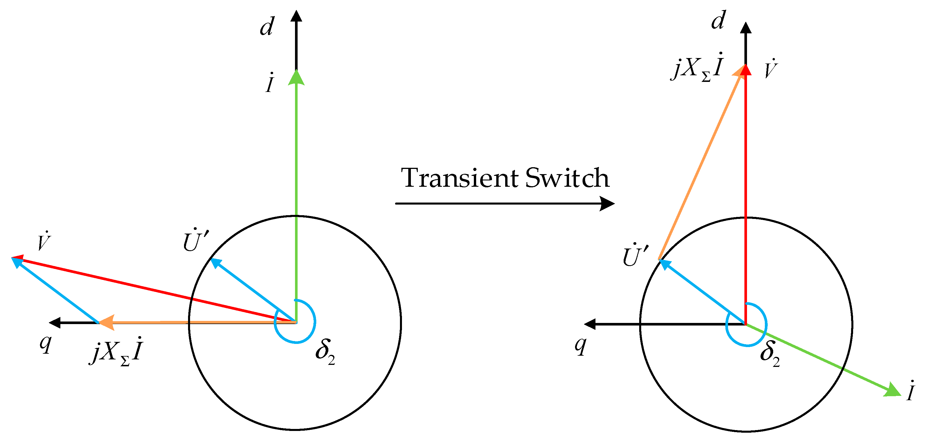
In this paper, δ is defined as the angle of the
d-axis leading grid voltage U, which can be regarded as the power angle of the converter. Based on the current saturation limitation strategy of the
d-axis priority adopted in this paper, when the converter is switched to current source, the current amplitude is determined by the limiting amplitude, and the phase is located on the
d-axis. The vector diagram of transient switching can be drawn according to Formula (2), as shown in
Figure 2.
According to Formula (1), the expression of the power angle change rate is shown in Formula (4):
Since the given value V
qref of the converter
q-axis voltage is usually set to 0, the converter output voltage V phase is consistent with the
d-axis, and the expression of the converter output active power is shown in Formula (5).
where X
Σ represents the sum of the grid side impedance and line impedance of the LCL filter, U represents the grid voltage, and V represents the output voltage of the converter.
When the output current of the converter becomes saturated, the converter power supply is switched from voltage source to current source. Based on the current reference limitation strategy of the d-axis priority adopted in this paper, combined with Formula (2), it can be seen that when the converter power supply is switched to current source, the current amplitude is determined by the limit amplitude, and the phase is located on the d-axis.
Therefore, when the current is saturated, the converter active power P
E can be calculated according to Formula (6).
where I
max represents the current limit amplitude, and U represents the grid voltage.
In order to filter out high-frequency disturbances, low-pass filtering is usually performed on the power detection value in droop control. The expression of the low-pass filter is as follows:
where P
f is the output active power of the filtered converter, and T is the time constant of the low-pass filter.
Combined with Formulas (4) and (7), the P-ω droop control’s dynamics can be expressed as:
According to Formula (8), the transient synchronizing stability’s dynamical formula for droop control is expressed as:
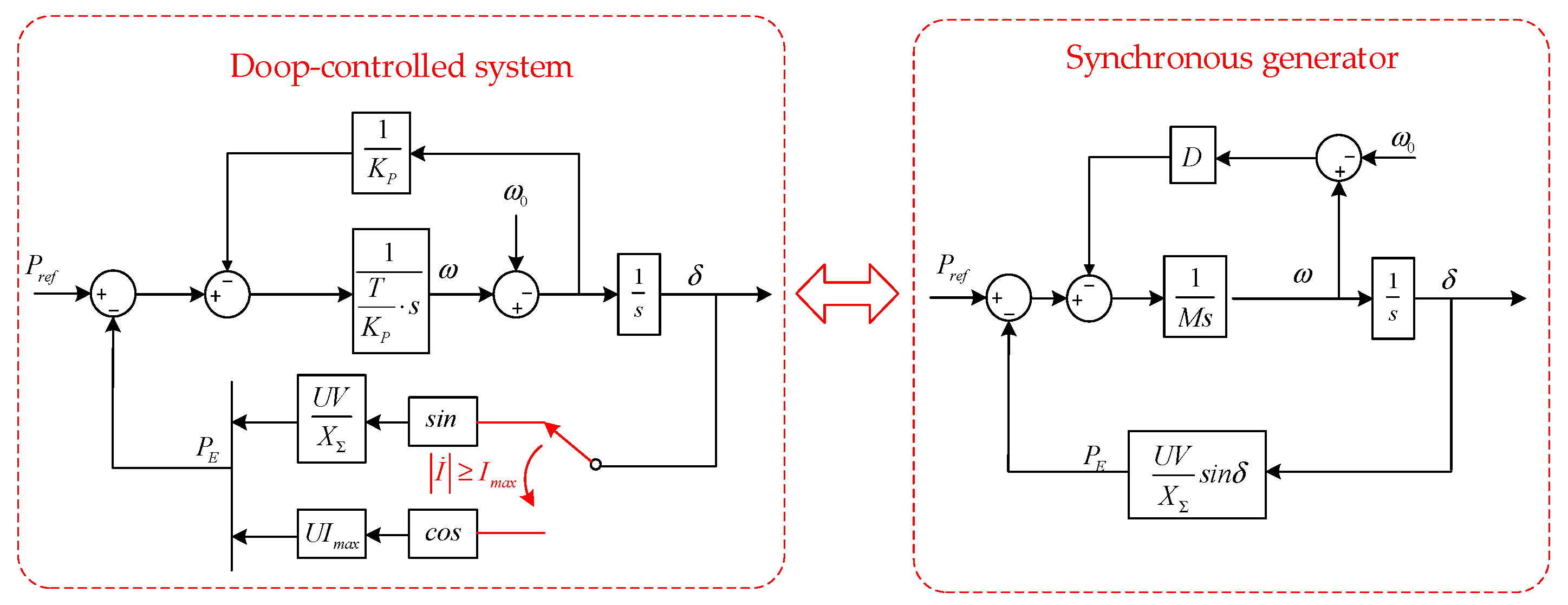
Therefore, according to the above analysis, the comparison between the models for the synchronizing dynamics in droop-controlled systems and the traditional synchronous machine’s rotor motion model can be drawn in
Figure 3.
As shown in
Figure 3, M and D represent inertia and damping, respectively. The deviation of the mechanical power input P
ref with restoring force drives the motion of the synchronous generator’s rotor. Due to the nonlinear relationship between restoring force and phase, the transient behavior is complex and may lead to a transient instability issue. And based on the above comparisons, it is intuitively clear that similar synchronizing control’s dynamics will exist in the droop-controlled system and the synchronous generator.
As a result, a similar large-signal instability issue will also occur in the droop-controlled system. Since the dynamical response of the droop control is much faster than that of the rotor motion, the instability should receive special attention. Based on the developed model, the equal area method widely used can be employed to carry out the large signal analysis. This will be explored in the form of a power angle curve in
Section 4.
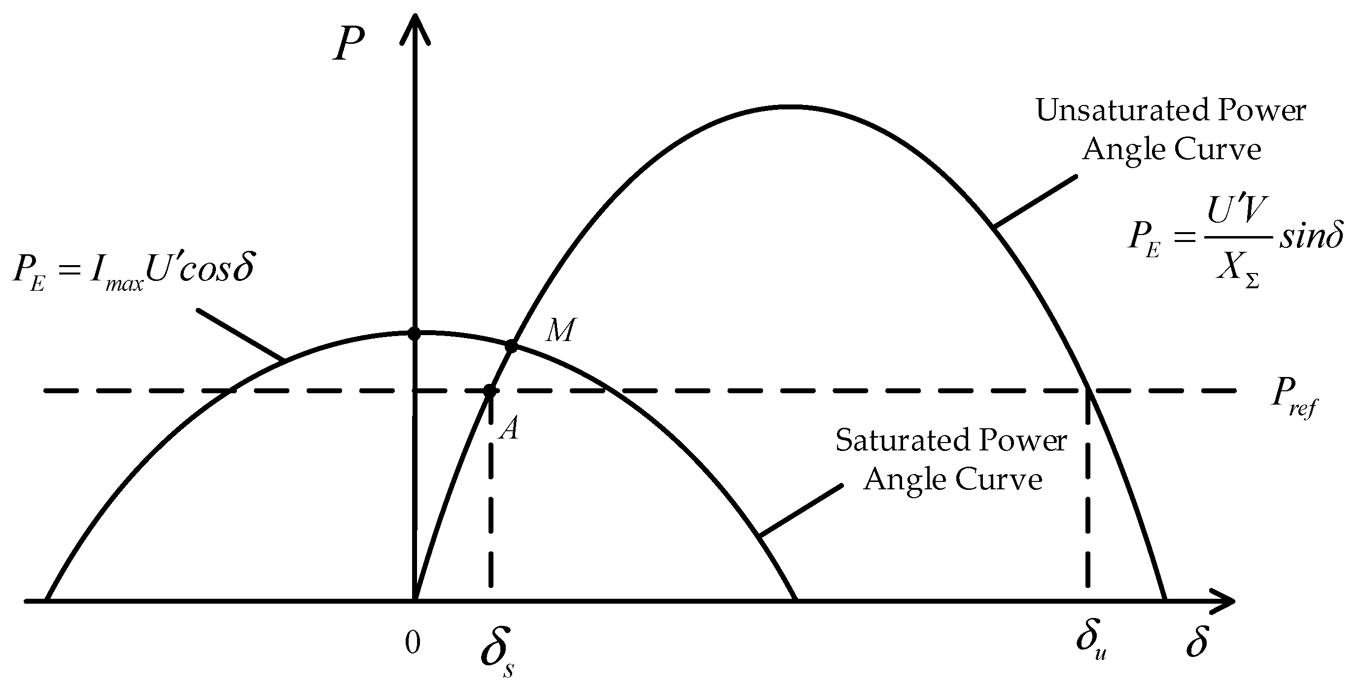
The power angle curve can be drawn according to Formulas (5) and (6), as shown in
Figure 4.
It can be seen from
Figure 4 that before the fault occurs, the stable equilibrium point of system operation is the intersection of the unsaturated power angle curve and the given power value P
ref, which is point A in the figure. And the corresponding power angle is δ
s.
According to
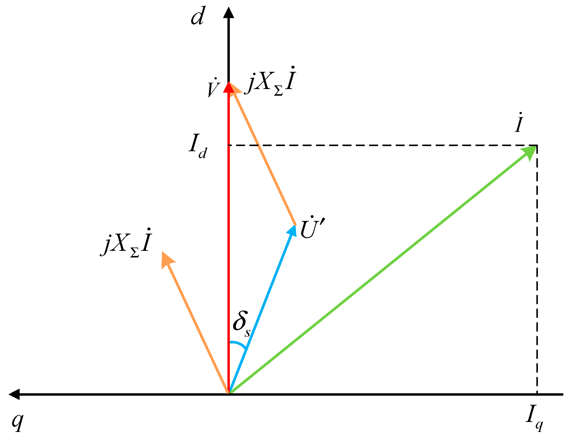
Figure 1, the converter output voltage is V, the output current is I, and the grid voltage is U. Because the line impedance is inductive, the relationship between them can be described by Formula (10), which is known as Kirchhoff’s Voltage Law (KVL):
According to Formula (10), the vector diagram of the system before the fault can be drawn, as shown in
Figure 5. It can be seen that when the system operates stably, the angle between the converter output voltage, output current and grid voltage is a fixed value, and the converter output current amplitude remains unchanged.
Assuming that the voltage amplitude of the power grid suddenly drops from U to U′, the process vector diagram is drawn as shown in
Figure 6. It can be seen that at the moment of the sudden drop in the grid voltage, the power angle δ does not change, and the converter output voltage V does not change either. From the vector diagram, it can be seen that the amplitude of the output current increases, and the
dq-axis components i
d and i
q also change.
According to
Figure 6, the amplitude relationship of the output voltage V, output current I and grid voltage U is shown in Formula (11):
where δ
s represents the power angle value of the stable equilibrium point of the system before the fault.
According to Formula (11), the degree of voltage sag at the moment of the power grid voltage fault determines the degree of sudden change in current amplitude after the fault; At the same time, the different line impedance XΣ will also affect the output current amplitude of the converter. On the premise that the current limitation amplitude Imax remains unchanged, the grid voltage amplitude U and line impedance XΣ determine whether the converter has the process of switching from voltage source to current source.
Therefore, during the premise of different voltage drop degrees, this paper will analyze in detail the influence of the line impedance XΣ on the synchronizing stability of the system after a fault.
4. Synchronizing Stability Analysis during Gird Fault
In this section, the synchronizing stability of the droop-controlled converter under voltage sags is analyzed using the unsaturated and saturated power angle curves derived in the previous section. According to the established model and dynamic Formula (9), the deviation between the output active power PE and the given power Pref can drive the acceleration or deceleration of the angular frequency of the converter. Therefore, the area below Pref can be defined as the acceleration area, and the area above Pref can be defined as the deceleration area. If the working point of the system remains stable after passing through the acceleration and deceleration areas, the system will stabilize at an equilibrium point, which is the intersection of the power angle curve and the given power value Pref. Therefore, the power angle’s dynamic behavior is analyzed to evaluate the synchronizing stability, similar to the power angle curve analysis for the synchronous generator’s transient stability.
It can be seen from
Figure 4 that the degrees of grid voltage drop determine whether there is an intersection between the saturated power angle curve and the given power value P
ref after the fault. Therefore, it can be defined that in the case of a medium fault there is an intersection, but in the case of a severe fault, there is no intersection. Formula (12) can be used to describe this definition.
4.1. Medium Grid Voltage Sag
The sufficient and necessary condition for the system to remain stable after a grid voltage sag is that there is an intersection between the power angle curve and Pref. And which power angle curve the system’s working point is in depends on whether the output current of the converter can be saturated after the fault. Therefore, judging whether the converter could directly enter the current saturation mode after the fault is of vital importance, and the line impedance will affect the amplitude of a converter’s output current, which is an important factor.
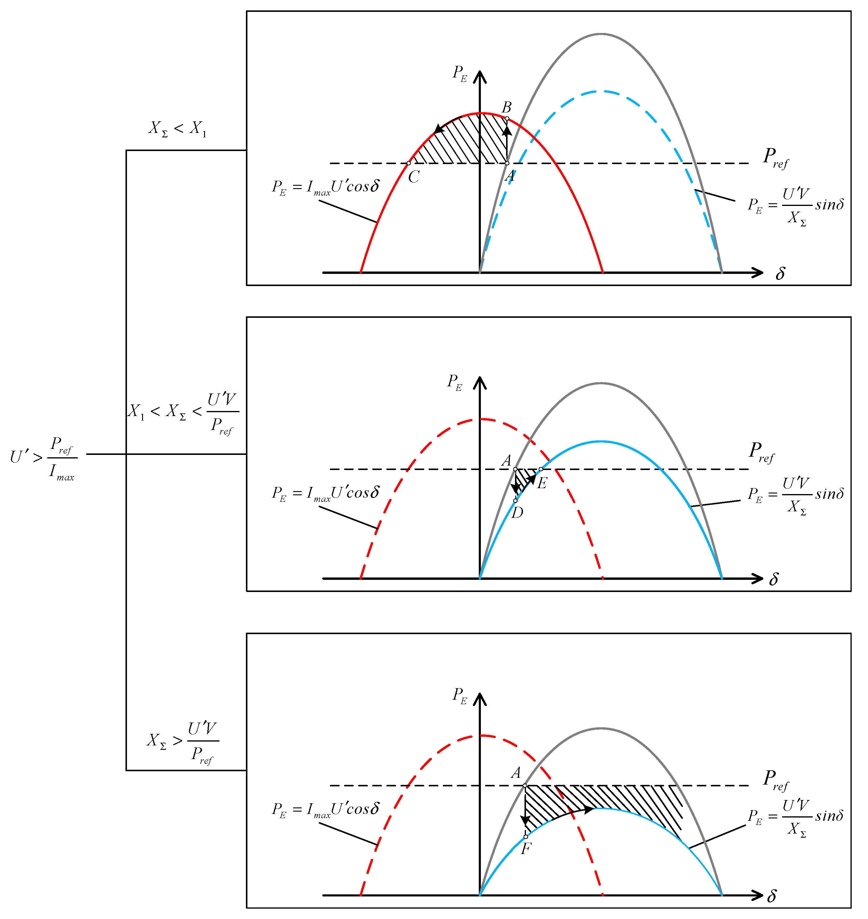
According to the different size of line impedance X
Σ, the synchronizing stability analysis of the system after the fault can be divided into three cases. The power angle curve of the three cases is shown in
Figure 7. In the figure, the blue curve represents the unsaturated power-angle characteristic curve, and the red curve represents the saturated power-angle characteristic curve.
The first case in
Figure 7 shows the case that the line impedance is small. When the power grid fault occurs, the converter directly enters the current saturation mode, and the working point of the system is located at the saturated power-angle curve. The converter power supply is switched to the current source. Because there is an intersection between the saturated power-angle curve and P
ref, the system will remain stable in the current saturation mode. However, it is not an ideal working state, because the converter is still a current source, and the voltage cannot be stably controlled. This is not desirable in industry. The second case in
Figure 7 shows the case that the line impedance increases. When the fault occurs, the converter will not enter the current saturation mode, so the working point of the system will be located at the unsaturated power-angle curve. The converter power supply remains a voltage source. And because there is an intersection between the unsaturated power-angle curve and P
ref, the system could remain stable after the fault. When the line impedance is large, the converter will not enter the current saturation mode after the fault. Although the working point of the system is located at the unsaturated power-angle curve, there is no intersection between the unsaturated power-angle curve and P
ref, and the system will become unstable. This case is shown as the third case in
Figure 7.
The above three situations will be explained respectively as follows.
4.1.1. The Case of XΣ < X1
Assuming that while the line impedance XΣ is X1, the output current amplitude of the converter just changes to the limit amplitude Imax at the moment of the fault. X1 is defined as the critical line impedance value.
Therefore, in the case of XΣ < X1, when the fault occurs, the working point of the system suddenly changes from stable equilibrium point A to point B. Since the output active power PE of point B is greater than Pref at the time, the system is in the deceleration area, the power angle of the converter will be reduced, and the working point of the system will finally operate at point C of the stable balance point.
According to Formula (11), the expression of X
1 is shown in Formula (13):
4.1.2. The Case of X1 < XΣ < U′V/Pref
When the fault occurs, the working point of the system suddenly changes from the stable equilibrium point A to point D. Since the output active power PE at point D is less than Pref, the system is in the acceleration region, the converter power angle increases, and the working point finally stabilizes at the intersection of the unsaturated power angle curve and Pref, which is point E in the figure.
Point E is the stable equilibrium point, and since the current is not saturated at this time, the converter is still a voltage source. Therefore, in this case, the system can still operate stably after failure.
4.1.3. The Case of XΣ > U′V/Pref
When the fault occurs, the working point of the system will suddenly change from point A of the stable equilibrium point to point F, which is in the acceleration region, so the power angle of the converter will continue to increase. At this time, there is no intersection between the unsaturated power-angle curve and the given power value Pref, so the stable equilibrium point does not exist, and the system is synchronizing unstably.
4.2. Deep Grid Voltage Sag
When the grid voltage falls seriously, according to the different size of line impedance X
Σ, the synchronizing stability analysis of the system can be divided into two cases. As shown in
Figure 8, when the line impedance is small, the converter directly enters the current saturation mode after the fault, and the working point of the system is located on the saturated power-angle curve. The converter power supply is switched to the current source. Because there is no intersection between the saturated power-angle curve and P
ref, the converter’s power angle continues to increase, and the system will become unstable. As shown in
Figure 9, when the line impedance is large, the converter will not directly enter the current saturation mode after the fault. But with the power angle increasing, the converter power supply will switch between a voltage source and a current source. This situation is special and rare. It is the focus of this article and will be analyzed in detail in
Section 4.2.2.
4.2.1. The Case of XΣ < X1
According to the previous analysis, when X
Σ is less than X
1, the output current of the converter becomes saturated at the moment of voltage sag, and the converter power supply is switched to a current source. The power-angle curve of this process is shown in
Figure 8.
It can be seen from
Figure 8 that after the fault occurs, the working point of the system suddenly changes from point A of the stable equilibrium point to point B. Due to the output active power, P
E is less than P
ref at point D, the system is in the acceleration area, and the power angle of the converter continues to increase. Because there is no stable balance point, the system cannot be stabilized, and synchronizing instability occurs.
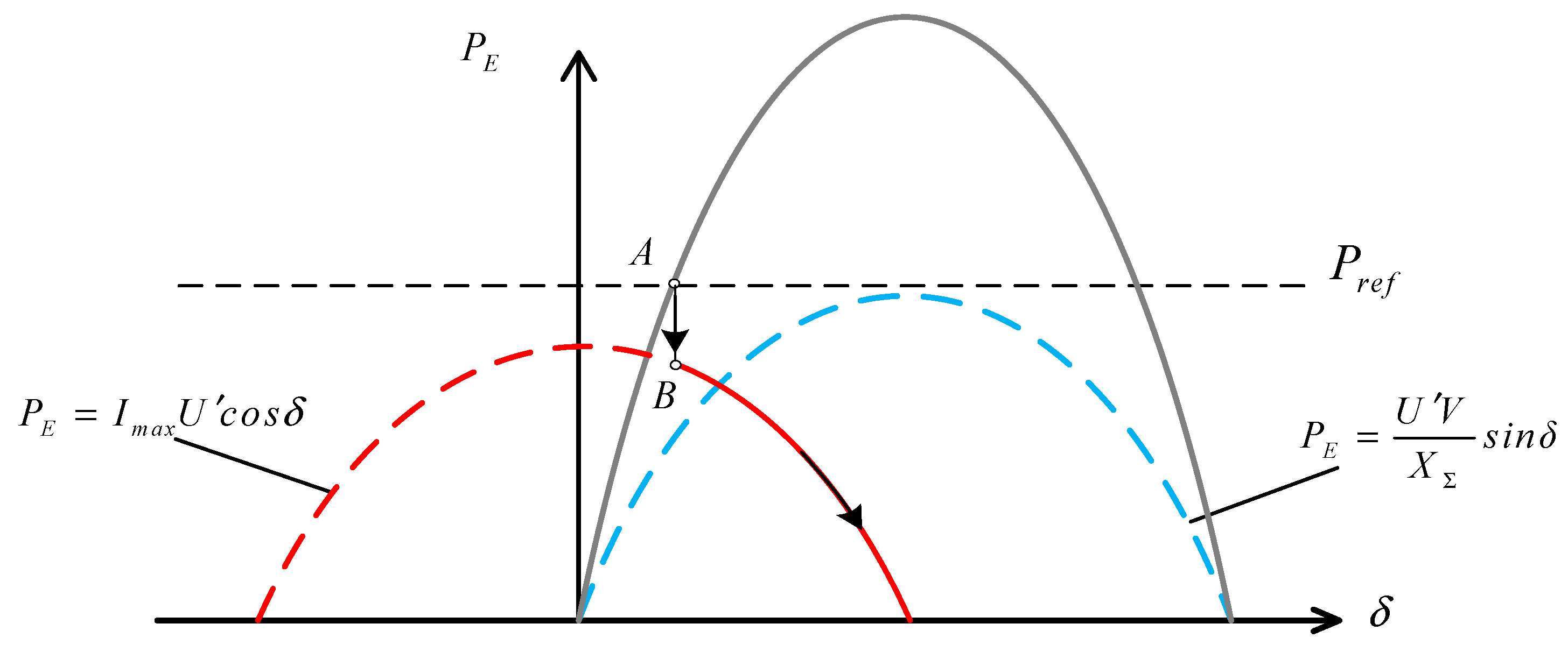
4.2.2. The Case of XΣ > X1
When X
Σ is greater than X
1, at the moment of voltage sag, the output current of the converter is unsaturated, and the converter power supply is still a voltage source. The power-angle curve of this process is shown in
Figure 9.
As shown in
Figure 9, after the fault occurs, the working point of the system suddenly changes from the stable equilibrium point A to point B, and the current is not saturated. At this time, the converter output power P
E is less than P
ref, and the converter power angle continues to increase.
It can be seen from vector
Figure 10 that with the increase in power angle δ, the output current amplitude of the converter gradually increases. When the system power angle increases to δ
1, the output current amplitude of the converter reaches the limited amplitude I
max, making the current limitation module in
Figure 1 respond. The phase of the output current is quickly positioned on the
d-axis, and the converter power is switched from voltage source to current source. In
Figure 9, it is shown that the working point suddenly changes from point C to point D, and the power angle continues to increase.
In
Figure 10 it can be seen from the voltage control loop in
Figure 1 that as the power angle increases, the amplitude and phase of the converter output voltage change at the same time, so that the i
d* and i
q* input to the current limitation also changes. The vector change of this process is shown in
Figure 11.
It can be seen from
Figure 11 that when the power angle of the converter increases to δ
2, the current command input to the current limitation decreases to less than the limited amplitude I
max, the limitation module is out of function, the converter power supply is switched to the voltage source again, and the output voltage is positioned on the
d-axis. This process is shown in
Figure 9 of the power angle curve: the working point suddenly changes from point F to point G, and the power angle continues to increase.
5. Simulation Verification
Simulation studies are carried out on a MATLAB/Simulink platform to verify the above synchronizing stability analysis. In the simulations, the voltage source converter system depicted in
Figure 1 is considered, and the detailed simulation parameters are shown in
Table 1.
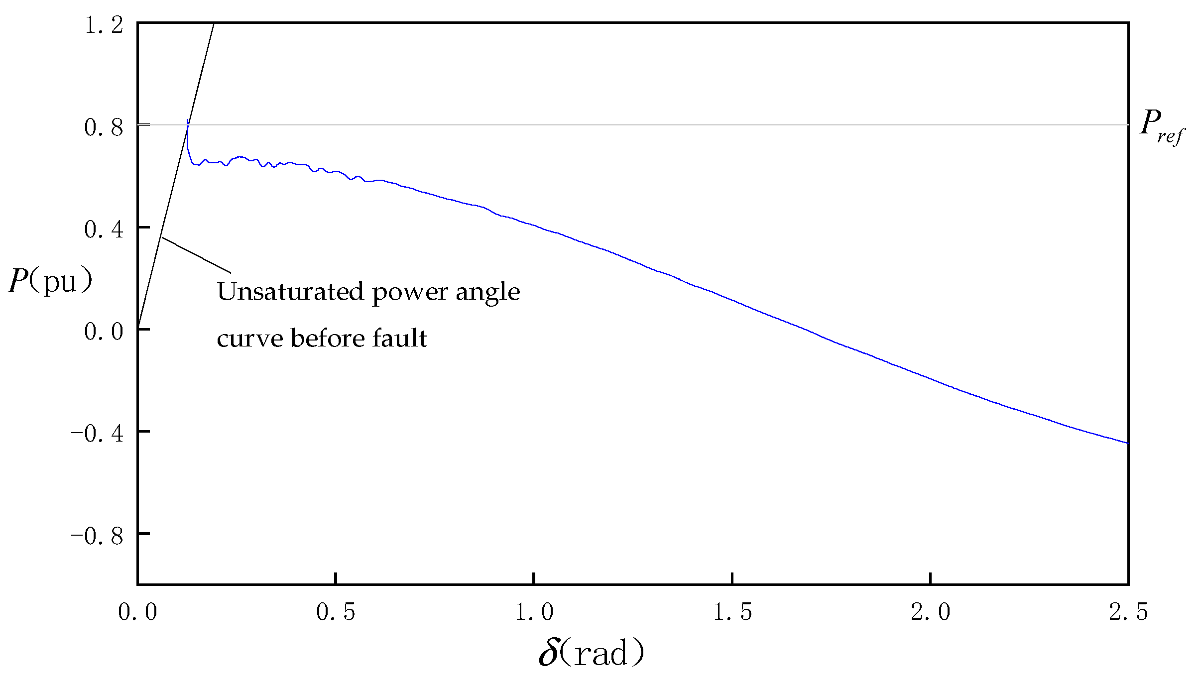
Under normal conditions, the converter operates stably in the condition of the given power value Pref = 0.8 pu, and the voltage amplitude of the power grid before the fault is U = 1.0 pu. When the medium voltage sag occurs, the grid voltage drops from 1.0 pu to U′ = 0.7 pu.
When the line impedance is small (X
Σ = 0.16 pu), the simulated power angle curve is shown in
Figure 12. It can be seen that the output current of the converter is directly saturated at the moment of fault, and the converter power is switched to current source. After the fault, the power angle continues to decrease, and the working point finally stabilizes at the intersection of the saturated power-angle curve and the given power value P
ref.
When the line impedance increases (X
Σ = 0.3 pu), during the same degree of voltage sag, the simulated power-angle curve is shown in
Figure 13. It can be seen that after the line impedance increases, the current will not be saturated after the fault, and the converter is still a voltage source. After the fault, the power angle increases, and the working point finally stabilizes at the intersection of the unsaturated power-angle curve and the given power value P
ref.
When the line impedance is large (X
Σ = 1 pu), the simulated power-angle curve is shown in
Figure 14. It can be seen that when the voltage sag occurs, the power angle continues to increase, and the converter cannot maintain synchronism with the grid which leads to synchronizing instability. But at this time, the output current of the converter is not saturated.
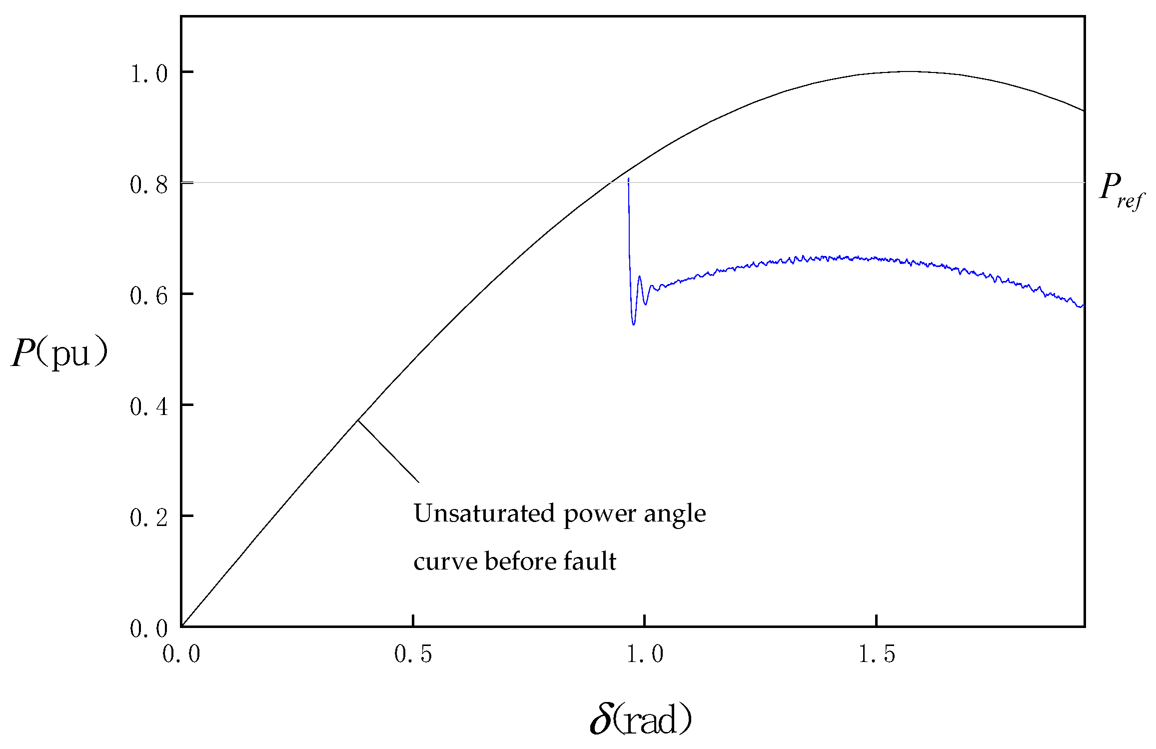
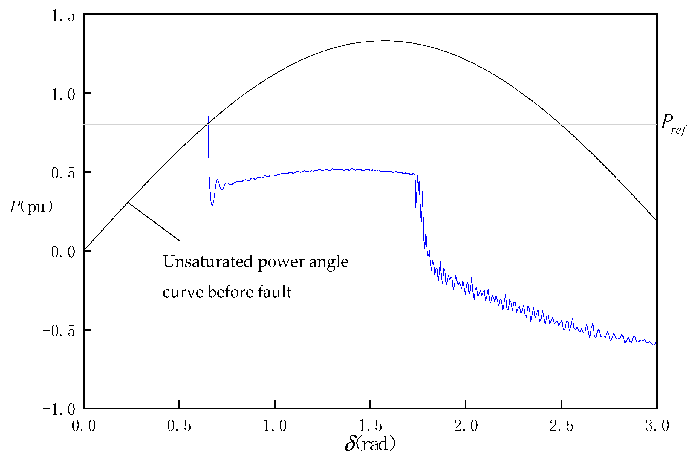
When the deep voltage sag occurs, the grid voltage drops from 1.0 pu to U′ = 0.4 pu.
When the line impedance is small (X
Σ = 0.16 pu), the simulated power-angle curve is shown in
Figure 15. It can be seen that due to the deep sag in voltage amplitude, the converter enters the current saturation mode after the fault. The power angle continues to increase, and the converter cannot maintain synchronism with the grid which leads to synchronizing instability.
When the line impedance is large (X
Σ = 0.75 pu), the simulated power-angle curve is shown in
Figure 16. It can be seen that when the voltage sag in the power grid is large, due to the large line impedance, the current at the moment of fault is not saturated. The converter cannot maintain synchronism with the grid and the power angle continues to increase.
When the power angle increases to a certain angle, the output current amplitude increases to the limited amplitude Imax and the converter enters the current saturation mode. As the power angle continues to increase, the converter switches between voltage source and current source.
From the above simulation results, it can be seen that each situation in the analysis in
Section 4 can be verified by the simulations. It proves that different degrees of the grid voltage sag will have a different impact on the synchronizing stability of the system. And when different line impedances are considered, the analysis will become more complex. The conclusions on whether the system could remain stable after the fault will be presented in the next section.
6. Conclusions
In this paper, the transient synchronizing stability of a droop-controlled converter during a grid fault was studied, with the influence of the current saturation limitation considered especially. An equivalent motion model similar to the rotor motion of a synchronous generator was developed to depict the transient synchronizing dynamics. The equal area criterion was employed to reveal the transient stability with the influence of grid impedance and grid voltage sag considered. The specific conclusions are as follows:
In the case of medium grid voltage sag, when the line impedance is small, the output current of the converter is saturated after the fault, and the system can maintain stability. Because the current is still saturated, the converter is still a current source, and the voltage cannot be stably controlled. With the increase in line impedance, the output current of the converter becomes unsaturated after the fault, but the system can still maintain stability. When the line impedance continues to increase to a certain value, even if the current is not saturated after the fault, the instability will still occur in the converter.
In the case of the deep grid voltage sag, the system cannot maintain stability, and the power angle will continue to increase. When the line impedance is small, the converter directly enters the current saturation mode after the fault. However, when the line impedance increases, the converter enters the current unsaturated mode after the fault first. As the power angle continues to increase, the current becomes saturated, and the converter switches between voltage source and current source.
In conclusion, this paper theoretically explained the transient process of converters switching from voltage source to current source under voltage sags, which could be applied to practical projects to prevent the power electronic equipment in converters from being damaged by overcurrent. Moreover, the analysis in this paper of the transient synchronizing stability under large disturbances paves the way for the follow-up research on the synchronizing stability of multi-converters and the corresponding control methods to improve synchronizing stability.


