Article

Structured Development of Digital Twins—A Cross-Domain Analysis towards a Unified Approach

Business Informatics-Communications Engineering, Business School, Johannes Kepler University, 4040 Linz, Austria
*
Author to whom correspondence should be addressed.
Processes 2022, 10(8), 1490; https://doi.org/10.3390/pr10081490
Submission received: 1 July 2022 / Revised: 26 July 2022 / Accepted: 27 July 2022 / Published: 28 July 2022
(This article belongs to the Section Advanced Digital and Other Processes)

Abstract

:
Digital Twins (DT) as digital representations are increasingly becoming operational design tools in a variety of contexts. Although a common understanding of the concept and the underlying development procedure would facilitate DT applications, only limited information has been published on the essential stages of development and fundamental development activities. This paper examines the extent to which an abstract, and thus generally applicable model for the development of Digital Twins can be identified. In order to come up with such a reference procedure, a structured analysis of published development experiences has been performed. Three major application domains, namely product lifecycle management, manufacturing, and predictive maintenance, could be detailed and cross-checked. For each of these domains, a contextual development model could be derived from empirically valid design and engineering practices. The data also allowed for the determination of which way each model corresponds to existing Digital Twin concepts. The use of a standard modeling notation enabled the integration of the domain-specific models into a single Digital Twin development model. As a result, developers are guided by domain-independent and -dependent development steps. Due to its generic structure, the model can serve for further domain explorations.

1. Introduction

The role of Digital Twins (DTs) as key enablers for the implementation of cyber-physical systems (CPSs) in the context of Industry 4.0 is becoming increasingly important [1]. The underlying concept of DTs has already been described extensively in the literature. Conceptual knowledge stems from a variety of studies, including those on autonomous vehicles [2], product development [3], manufacturing [4], intelligent production [5], and model-based development [6].
However, most sources provide limited insight into the essential steps and fundamental activities for developing and maintaining the respective implemented concept. For this reason, a cross-domain analysis should shed light on underlying organizational structures and processes supporting the development and advancement of DTs. The demand for a model, distilling major stakeholder roles and tasks along fundamental development steps, has been articulated in several studies, including industrial application [7] and surveys [8], and application frameworks [9].
Once these steps stem from valid empirical studies, an integrated model across domains can be constructed to facilitate further development projects. However, the challenges of such an endeavor are
  • to identify relevant information (roles, activities, etc.) from empirical studies
  • to abstract from domain-specific particularities and specify a proper level of abstraction in order provide a frame of reference for further DT developments.
The objectives of this study are first to identify reliable empirical data sources from published DT development experiences (we term them in-depth studies in this work), and then to analyze the provided information describing the development practice in a contextual form, in particular defining the domain of the DT, the roles of involved stakeholders, the development activities, the data to be processed for design and engineering, and the steps to follow to complete a development procedure.
On that basis, the next objective is to create a development model based on the (domain-) specific approaches in the sense of an integrated model for the development process of a DT as independently as possible of the respective application domain. Accordingly, we are interested in the following two research questions:
  • Research Question 1: What empirically valid knowledge (in form of in-depth studies) exists (in different application domains) about the process for developing DTs?
  • Research Question 2: In how far can a generally applicable model be defined for the construction and further development of DTs?
On the one hand, the first research question serves to understand the development processes in the context of the currently applied DT concepts, while on the other hand, it provides the prerequisites for answering the second research question by identifying process-relevant information, including stakeholder roles, development activities, relevant information, and development steps.
We proceed as follows. After a brief introduction of DTs as development assets and their current development practice in Section 2 (Literature Review), Section 3 addresses research question 1 for the identified categories of application domains—product life cycle management, manufacturing, and prediction. For each domain, a generalized process model for development is presented. We build on the three models when addressing the second research question. Consequently, in Section 4, we define a cross-domain model as a reference for constructing and developing Digital Twins. It captures domain-independent as well as domain-specific development steps, and has been evaluating running a test case. A critical reflection of the results and proposed further research are given in Section 5 (Discussion). Section 6 concludes the paper.

2. DT Literature Review

In this section the understanding of Digital Twins and the state of affairs for this work, in particular what challenges should be met with respect to the development process, is provided. We show the diversity of approaches to conceptualize DTs and development challenges in the context of Cyber-Physical Systems (CPSs). These conceptualizations also represent the context of the subsequent analyses.
Digital twinning is becoming key for Industry 4.0 developments, including Cyber-Physical Systems (CPSs), and Internet of Things (IoT) applications [10]. The authors of “Digital Twin-driven smart manufacturing: Connotation, reference model, applications and research issues” recognize a significant increase in the importance of the DT concept in recent years as having the potential for transforming current and future production [5]. The term DT originated in the field of aeronautics; however, in recent publications the underlying concept is mainly associated with applications in manufacturing [5].
According to [6], the concept of DTs was first mentioned in 2000 by Michael Grieves in the context of manufacturing. He dates the concept back to a presentation on the development of a Product Lifecycle Management (PLM) center at the University of Michigan, [3] while [4] dates this work to 2003. The concept is based on the idea that a digital information construct can be created using a physical system as an independent object. This digital information is called a “twin”; it forms the virtual representation of the physical object and is linked to this physical object throughout its lifecycle by mutual data synchronization [3]. Hence, the underlying research area deals with PLM [4]. After the first multi-physical, multi-scalable, and probabilistic simulation of a vehicle using a physical model that was continuously updated by sensors [2], a first conceptualization of DTs enabled the development of DTs in several industries, which has led to a variety of further DT understandings [10].
Meanwhile, DT applications are reported in numerous industries, such as industrial manufacturing, aviation, healthcare, and the communications industry, for which the concept must meet different requirements [4]. In addition to smart manufacturing and Industry 4.0 and thus the development of cyber-physical systems in production [10]—machine learning, mobile communication and cloud computing were drivers of DT development in the direction of simulation [5].
The digital representation of DTs can map the entire product life cycle of the physical item and also take dynamic changes into account through ongoing synchronization with virtual mapping [5]. As a virtual representation of a physical asset, DTs have become a digital reference point for the development of production, services and business organizations. This is enabled by data and simulation for the purpose of real-time prediction, optimization, monitoring, control, and improved decision-making [6]. The step towards real-time operation has been accompanied by a differentiation of DT categories [6]:
  • Virtual Twin—a virtual representation is created based on a physical asset (in the cloud)
  • Predictive Twin—physics, data, or hybrid models based on a virtual twin in order to predict behavior of a physical asset
  • Twin Projection—the data obtained through the predictive twin is analyzed in order to gain insights in terms of underlying operations and processes
Although DT, CPS, and IoT are different concepts, they share some common characteristics. According to [5], all of them have in common that they use networks and sensors to communicate with or retrieve data from other systems and their environment. The CPS fundamentally encompasses the physical assets, such as a plant or production facility, and the digital representation of that physical object.
Since the DT is limited to the digital model, it cannot exist without a connection to the physical world or without the existence of the physical asset itself. If in control of the physical asset, the DT needs to be considered as an inherent part of a CPS and its development, with IoT representing the network for exchanging data between physical assets [5]. In Figure 1 the relationship between the digital twins and physical assets in cyber-physical settings is illustrated.
The DT is characterized by a two-way dynamic mapping between a physical object and a virtual model in cyberspace. In this context, the DT represents a kind of middleware architecture, which is an abstraction of the physical object and claims that the system can make a decision in nearly real-time [5]. From a technical point of view, three different building blocks are required for the development of a DT.
First, there needs to be an information model that represents an abstraction of the physical object. Secondly, a communication mechanism must exist that enables communication between the physical asset and its virtual representation in both directions and in real time. Status changes of the physical asset are detected by sensors and transmitted to the DT. Finally, a module is required that can extract and process the data collected in the process in order for the model of the virtual representation to be created [5]—see Figure 2.
Although depending on the application domain, the requirements for a DT may vary, simulation and prediction of behavior is a key aspect of DTs [10]. The authors of “Requirements Driven Digital Twin Framework: Specification and Opportunities” [11] cross-checked requirements for DTs, and could identify (i) general requirements, such as the clear definition of boundaries and relationships with the physical object; (ii) requirements stemming from existing DT implementations, including re-usability, interoperability, interchangeability, and maintainability; and (iii) anticipated requirements derived from trend studies, including support for the entire ecosystem for detection, prediction, and analysis.
Although the DT concept is already in practical use in some areas, there are numerous challenges associated with its implementation. The overarching challenge here is to develop the DT in such a way that it is hardly different from its physical counterpart, which results in considering a variety of design and engineering solutions [6]:
  • With respect to data handling, issues of protection, security, and quality should be supported by cryptography, blockchain, and Big Data technologies.
  • Real-time communication should be supported through compression techniques or proper communication technologies including 5G and IoT protocols.
  • Real-time modeling and modeling the unknown requires combined sensing, symbolic regression, reduced order modeling, or multivariate data-driven models along cybernetic life cycles in order to continuously update an existing model.
  • Interfacing physical assets technologically and organization-wise should be enabled through sensor technologies, physics-based simulation, data-driven models, and human-accessible interaction mechanisms such as natural language interfaces, augmented or virtual reality features.
  • The variability of system topologies requires edge, fog, and cloud computing approaches.
  • Maintainability should be based on transparent and interoperable architecting, allowing for hybrid analysis and modeling
In summary, it can be stated that the DT concept has so far not led to some uniform understanding of DTs. Following this insight, no generally valid approach can be expected with regard to the procedure for the construction and further development of DTs. As will be shown by our analysis, product lifecycle management is still a major application area and thus leads to considering development procedures from this perspective.

3. Material and Research Methods
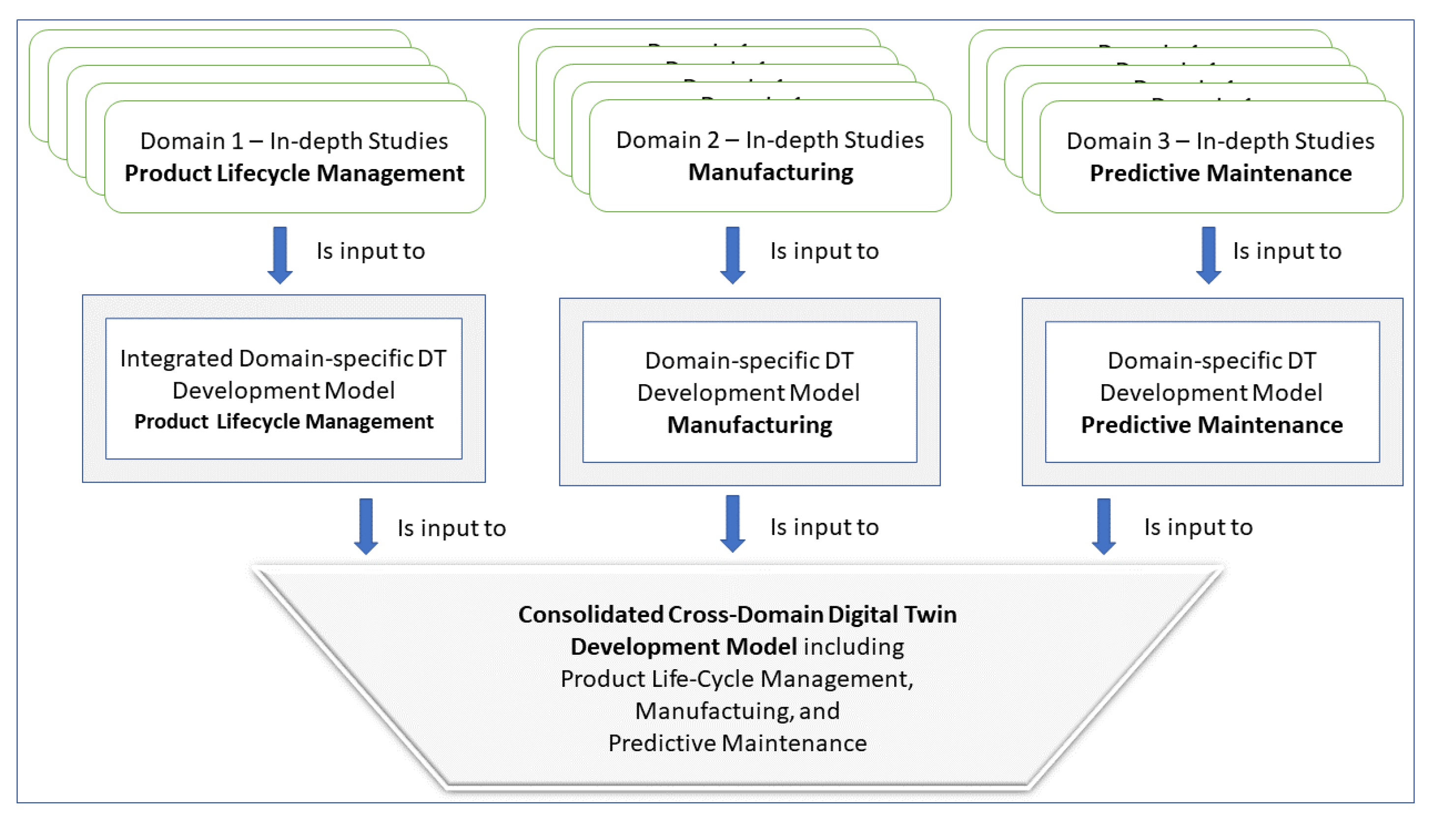
In this section we first provide insight into the selection and identification of studies that finally provided (i) sound empirical evidence in terms of one or more development cases in a specific domain, and (ii) a sufficient level of detail to extract relevant information on DT-construction and development processes. The latter included looking for the four main constituents of information required for structuring the development process, namely,
(1) concerned development stakeholders,
(2) development phases and activities to be set,
(3) information to be processed along the activities, and
(4) the flow of control and information in the course of design and engineering tasks, addressing the sequence of activities to be set.
The literature search included as basic term ‘digital twin’ when looking for processes or models for the development of DTs. The other terms either refer to the objects of concern in DT development, such as ‘product’, or empirical evidence of development practices, such as ‘case study’, ‘life cycle’, ‘implementation’, ‘validation’, ‘improvement’, ‘learning’, and ‘tuning’. As shown in Table 1, combining these terms with ‘digital twin’ helped to focus on detailed reports on DT development.
From the resulting fifteen sources, it was possible to obtain in-depth information with regard to DT development processes. The selected studies stem from three different domains: product lifecycle management (PLM), manufacturing, and predictive maintenance (see Table 2). In the area of PLM, five in-depth studies were selected, and in the area of production 10 in-depth studies are selected. The latter focus on the one hand on the monitoring of manufacturing processes in real time (seven selected in-depth studies in Table 2), and on the other hand on predictive maintenance (three selected in-depth studies in Table 2).
In the following we analyze each of the selected sources in the context of its domain and provide a consolidated, and thus domain-specific development model. The resulting three domain-specific DT development models (PLM, manufacturing, and predictive maintenance) served as inputs to an integrated development. In Section 4 we present the cross-domain development model. In this section we also determine which type of DT the domain-specific DT development models address.
Figure 3 shows the process of model development based on the selected in-depth studies. Evidence from each domain has been consolidated in terms of involved stakeholders or stakeholder groups, activities to be set in the course of DT design and engineering, data required and produced for DT development, and the sequence or flow of control to be followed for successful DT development. Finally, an integration of domain-independent and domain-dependent development processes has be performed to provide a cross-domain reference for DT development.

4. Results

In this section we present for each domain the presented information and the derived development process model.

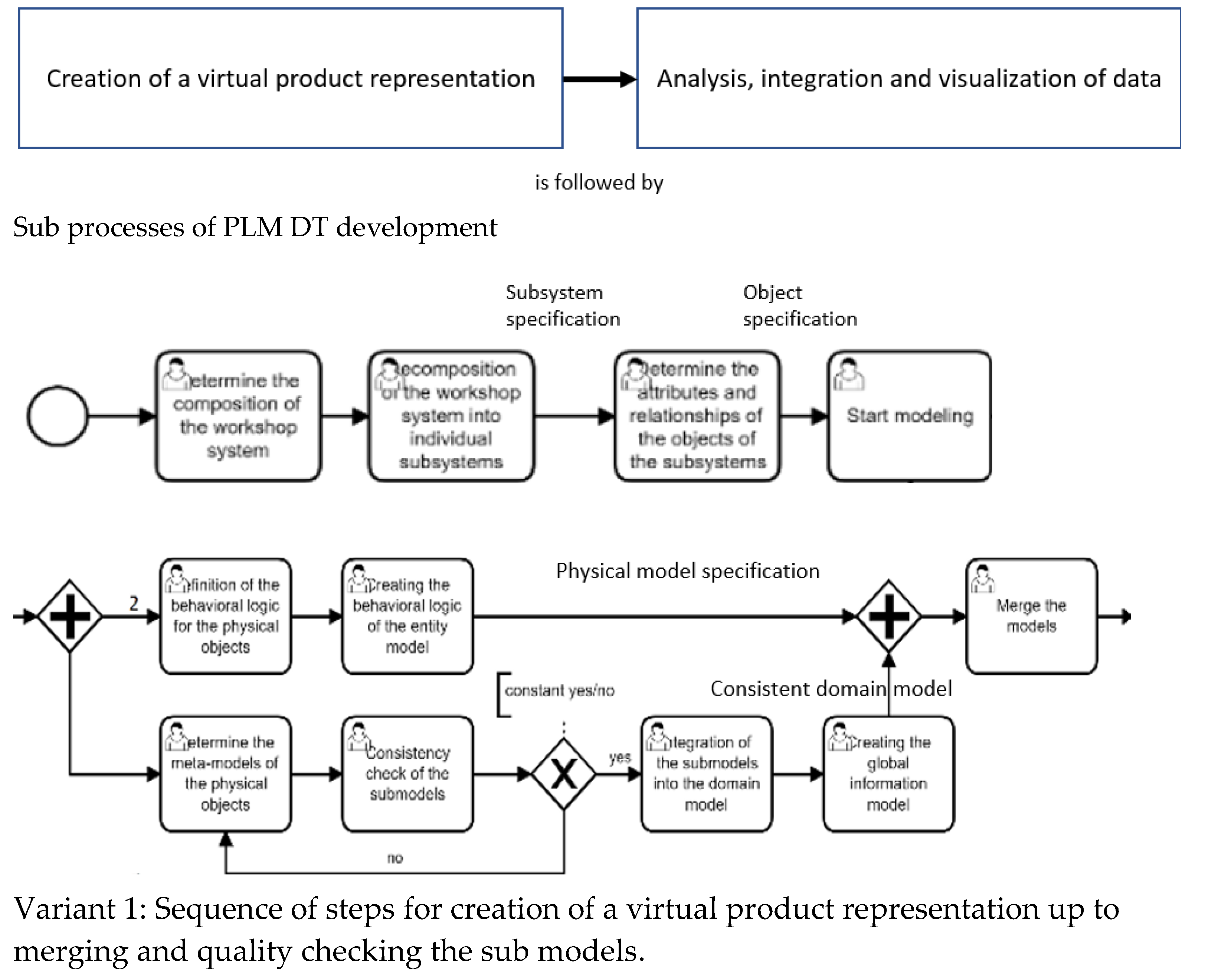
4.1. Product Lifecycle Management

In this section we describe the DT development approaches and abstract process-relevant findings from the empirical studies selected in the domain product lifecycle management (PLM). According to Table 2, three in-depth studies concern product lifecycle management and are included into this part of the domain analysis. They either tackle the entire product life cycle or part of it.
Zheng et al. [9], while recognizing the lack of a general application framework or reference solutions of successful implementations, consider DTs relevant for product design, operation, and maintenance. Since DTs have not yet widely been used in the production and test phases [9], the application development framework for DTs presented by the authors focused on a production-line case. The framework consists of three parts, the physical space, the virtual space, and the information/process layer. They enable a fully physical system mapping, dynamic lifecycle modeling, and the real-time optimization of the entire process. Bidirectional interoperability of the physical and virtual space is enabled through data interaction [9].
The virtual space comprises two parts. The first one is a virtual environment platform to represent a unified 3D model of the application with a library for algorithms, and a second one is a DT application subsystem for product lifecycle management. The virtual environment platform provides different virtual models, such as for simulations or workflow for the DT application subsystem. The subsystem, in turn, accumulates data from the physical space and feeds it into the virtual environment platform. A model of a physical object in virtual space is thus made possible by the attributes of the virtual model stored in the database.
The derived process model (Figure 4) can be used to illustrate the individual steps required in the development of the virtual model according to [9]. The rectangle shapes contain activities, the x-connector an exclusive control flow relation between activities, and the +-connector a parallel control flow of activities. The directed links represent the sequencing of activities between a start event (circle) and an end event (bold circle). For the sake of readability, the sequence ‘Analysis, Integration, and Visualization of Data’ has been bundled into the second part of the figure.
Before starting to model the attributes of the modeled objects need to be determined according to a specific decomposition strategy leading to sub systems. Modeling activities comprise the specification of the behavior in terms of the required business logic for each physical object and its digital representation. The latter includes a consistency check against domain requirements.
The “Digital twin-driven product design framework” [12] contains a framework for DT-based product development which was also given proof-of-concept in a case study. Here, IoT services are used to collect data from smart products, which can then be transferred to the cloud in real time and analyzed accordingly using cig data analytics. To coordinate the behavior in virtual and physical space, the framework synchronizes interactions. It allows improving a physical product in real time through a DT model. Again, a physical space is coupled with a virtual one by means of data links. The latter enable predicting the future behavior of the physical object, and thus continuous development through the DT—see the corresponding process model in Figure 5.
In the study on “Digital twin-driven product design, manufacturing and service with big data”, Tan et al. [13] explore opportunities for smart and sustainable manufacturing of product design and required services. For the optimization of the product lifecycle, the DT development focuses on users and their active participation in the design process. As a result, the product design process is increasingly transforming into a virtual and networked process.
Big data-driven product design is thus being used, as is cloud-based manufacturing—see figure on DT-based product design that has been derived from the data provided in [13]. The process model contains two major bundles, ‘creating the virtual representation of the physical product’, and ‘analysis, visualization and integration of data’, before a ‘virtual representation model’ is constructed. It requires simulation, behavior control, and setting up connectivity relations between the physical and digital twin.
Complementing the studies mentioned previously, Lin et al. [14] considered several aspects in the area of PLM and business innovation when integrating DTs into existing ecosystems. In this case, ontologies or the NoSQL database are used for data representation or computation, as well as models for extraction and analysis for the automation of decisions by DTs [14]. In the proof-of-concept study [15], a laboratory test was used to investigate the practicality of a DT concept.
To demonstrate the DT concept under laboratory conditions, a bending beam test rig was selected as the physical counterpart. The developed test bench consisted of a physical object, its DT and a communication interface to exchange data between the physical and virtual environment. The architecture allows additional clients to be included without having to modify the underlying system to exchange data between the physical and virtual object in a synchronized manner during operation. A dashboard (IoT (Internet of Things) platform) was created to control the physical and virtual object and display calculation results [15].
Based on the contextual descriptions of the construction and further development of DTs, a process model for the PLM domain could be derived. It is presented in Figure 6, and was constructed as follows. Tan et al. [12] contributed a comprehensive process description for the creation of digital twins. The reference process for PLM is therefore predominantly based on this model. From [9] an alternative approach to the creation of the virtual representation could be integrated, which is supplemented by the fundamental steps for the creation of a DT in the area of product design from [13] as well as [14]. The model coincides with the approach described in [15] for the development of DTs capturing the creation of virtual representations, the simulation of product behavior in a virtual environment, and the creation of a real-time connection between virtual and physical object.
Although the analyzed in-depth studies on PLM do not provide detailed stakeholder and data object information, the tasks could be bundled to identify role-specific behavior bundles. They are indicated by the rectangles in the process specification, and allow for the assignment of functional development roles, such as DT designer, which have not been provided by the original data. The reference process itself can be decomposed into three phases as already recognized by [13] for product design or may lead to two different variants of PLM DTs.

4.2. Manufacturing

In this section we derive a development model from in-depth findings published in the domain manufacturing, as constituent part of production processes. All manufacturing-relevant studies as indicated in Table 2 have been included in the analysis of this domain. They are described in the following.
Park et al. [16] introduce a development model for implementing a DT application for a smart factory. Here, a DT is designed and implemented as a digital representation of the process, and the presented DT application realizes tracking of past-related data, real-time monitoring of the production facility via IoT services, and a computational kernel for decision making with a view to the future [16]. For DTs in manufacturing, stable and efficient data integration and data management is a key success factor, which can be supported using frameworks for data construction. Kong et al. [17] identified three required modules of such frameworks, namely for data representation (ontologies), organization, and management.
For the integration of physical machines, tools, material handling, warehousing, and real-time manufacturing using DT, Wang et al. [18] proposes a framework for real-time monitoring of conventional machines. It includes three different modules, two of which are ascribed to digital space. The data-capture module is used in physical space and is responsible for capturing the data of the physical object, and is connected to virtual (digital) space for a two-way data transfer [18].
For ongoing digital monitoring and functional improvement of products, devices or machines, Stark et al. [19] were able to derive 8 dimensions for the design of the DT. The context is captured by integration breadth, connection mode, update frequency and product life cycle, while the behavior of the DT is addressed by CPS intelligence, simulation capability, digital model richness and human interaction [19].
When planning in production is addressed, especially for the integration of new products into an already existing production system, DTs can be created automatically. For body-in-white production in the automotive industry, i.e., the production stage for joining different shell parts [20], a concept for asset generation of the CPS of the production plant was developed by [21].
The CPS represents a set of embedded systems, which are interconnected via a network and thus can communicate and interact with each other. The goal is to reduce the time it takes to integrate new products into an existing system and optimize production. With the help of a bus system, it is possible to send information from a component of the CPS to a client, such as the DT. This message flow allows conclusions to be drawn about the latency of the production network by evaluating the timestamps of individual messages [21].
Increased efficiency in reconfiguration of manufacturing systems through the use of DTs is additionally expected to increase system availability and minimize setup time, as well as enable the production of customized products. Enablers are data warehouse architectures that have sensors for active data acquisition [22].
Reconfigurability addresses a key factor of DT lifecycles. These have already been captured in an object-oriented manner, and consider reusability, extensibility, and interoperability based on an offline development phase, and an online deployment and maintenance phase [11]—see also the enriched BPMN-model (https://www.bpmn.org, accessed on 30 June 2022) in Figure 7. There, yellow and green tasks denote on-line and off-line activities, respectively. However, the development model serving as reference for the manufacturing domain in Figure 8 was mainly derived from [22] due to the higher level of detail as required for general use. The individual steps for creating the DT are detailed according to the sub processes or phases in Figure 8, and described below.
  • Envision: Ideas and inputs to implement them are collected and documented.
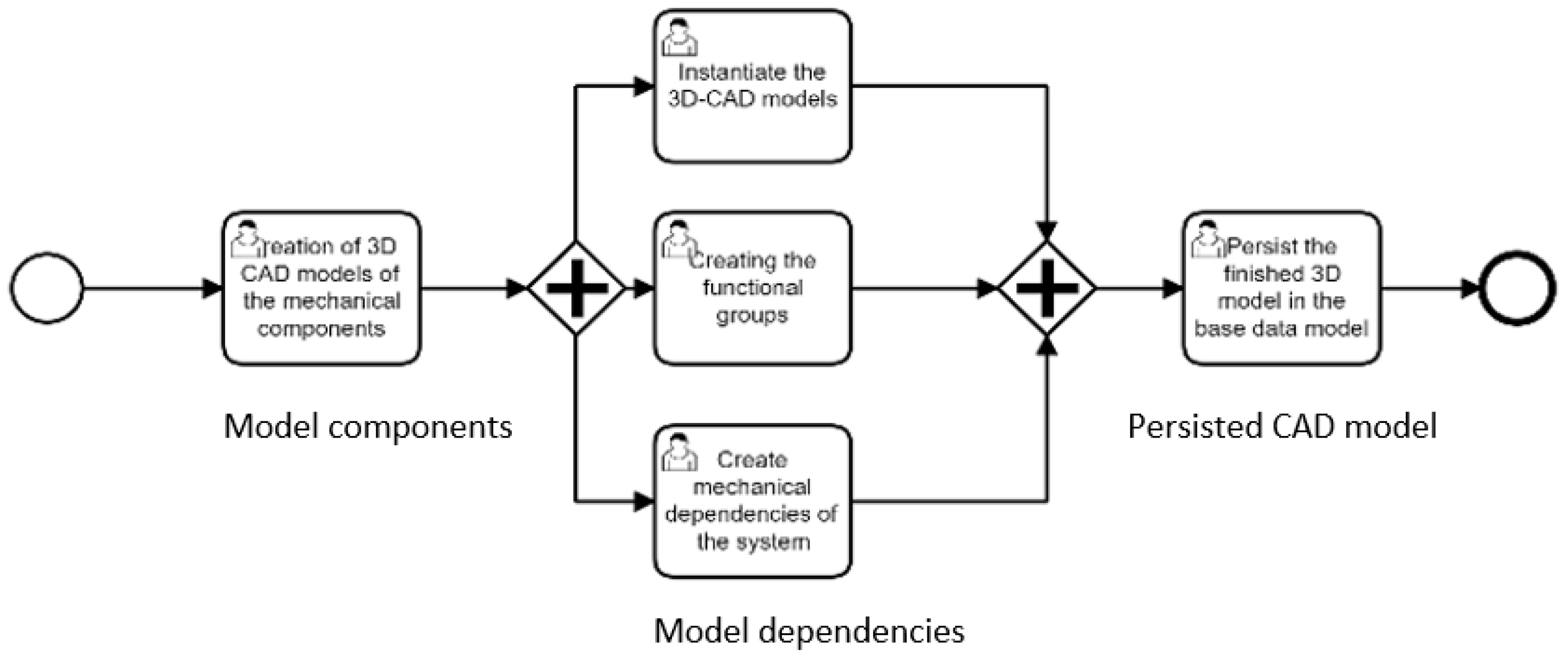
  • Design: (i) Creation of 3D CAD models of the mechatronic components of the system with some modeling tool; (ii) Instantiate the 3D models using a design tool, such as Line Designer, by accessing the base data model; (iii) The functional groups are added; (iv) The mechanical dependencies of the system are created; (v) The finished 3D CAD model is stored as a higher-level system model in the base data model.
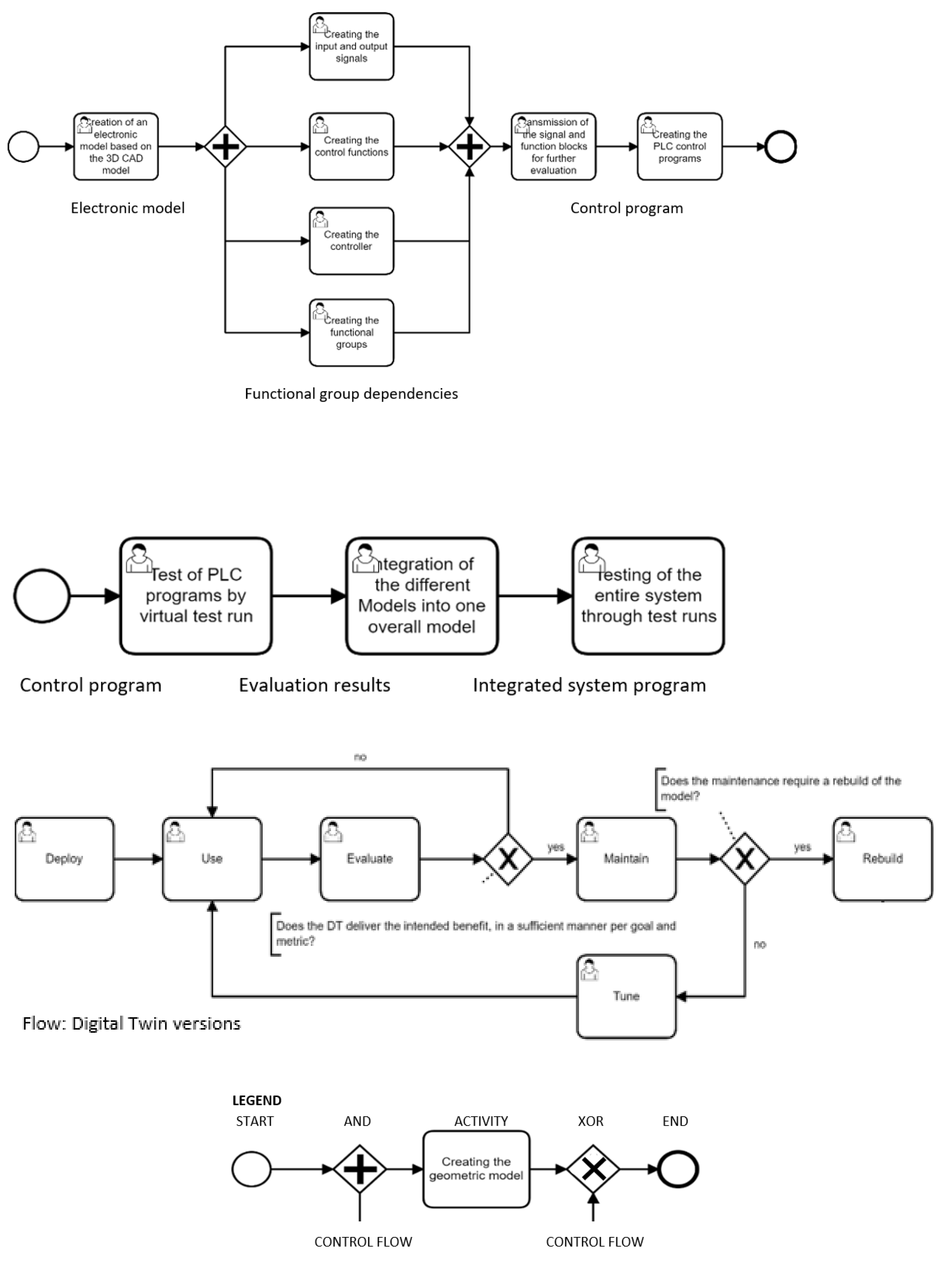
  • Develop: (i) Creation of an electronic model based on the 3D CAD model; (ii) Using a direct interface between Automation Designer and other tools, the input and output signals of the components as well as the control functions, controllers and functional groups are created; (iii) After the electrical model has been created, the signal and function blocks are transferred from Automation Designer to a portal; (iv) The PLC control programs are also created in this portal.
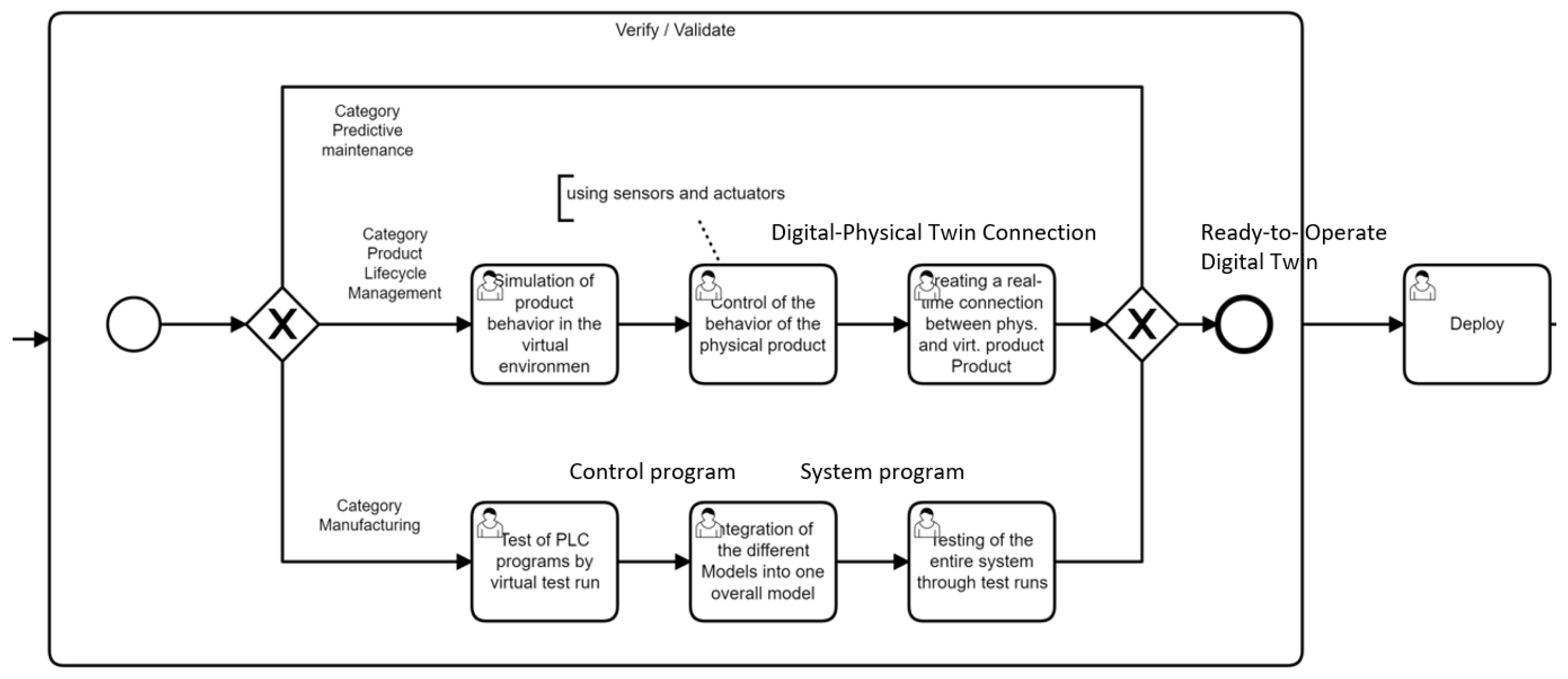
  • Verify/Validate: (i) The PLC programs are tested by virtual test runs; (ii) As different models of DTs are created, they are now integrated into an overall system; (iii) The overall system is again tested by virtual test runs, checking whether the overall system meets the requirements.
  • Deploy: After completion of the previously described model, it is deployed and can then be used.
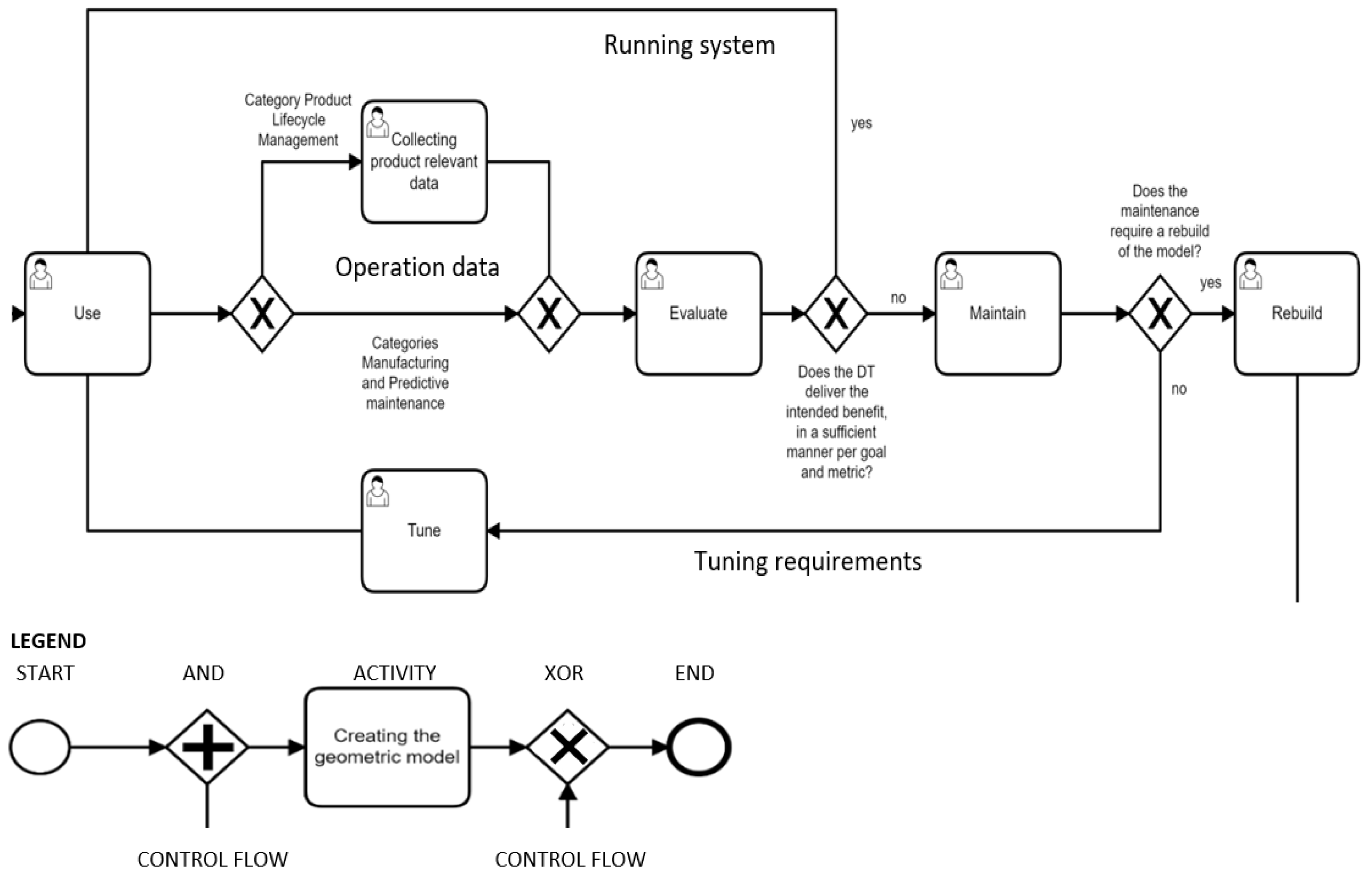
  • Use: After the system has been deployed, it can be used.
  • Evaluate: The system is continuously monitored and maintained if necessary, see subsequent step Maintain.
  • Maintain: The maintenance of the DT model can be achieved in two different ways, either by step Tune or step Rebuild.
  • Tune: The already existing model can be improved.
  • Rebuild: If maintenance requires rebuilding, re-design or re-development has to be performed.
The specification of tasks on that high level of abstraction allows to structure the studied contributions of the manufacturing domain, as they address specific tasks and thus support their implementation:
  • Park et al. [16] describes a DT architecture, which can be divided into four layers. The first two layers, including the IoT network, can be assigned to the physical environment, aside from the manufacturing application and the cloud application that can be assigned to the virtual environment. Utilizing the described architecture, Design, Development, and Verification are affected for the construction of the DT. It supports considering the efficiency in terms of cost and production, and affects the Use of DTs, and their further development (Deployment, Evaluation, Maintenance, Tuning, and Rebuilding).
  • Kong et al. [17] address the storage, integration, and analysis of data, which are major challenges in the development of DTs. The proposed framework for managing the data fits into the DT development model for production systems.
  • Wang et al. [18] show, analogous to [16], an architecture with three modules to implement the DT concept. The data capture module is responsible for capturing data from the physical space. The data module is used for data management and data processing. Lastly, the DT Intelligence module can be seen as the service part, where it also contains the logic for the dashboard to display the information. The connection between physical and virtual space for data transfer is solved via an IoT network. The described architecture thus coincides in its basic characteristics with the previously discussed work.
  • Stark et al. [19] defined 8 dimensions that contribute to the description of the behavior and context of a specific DT. With regard to specifying a DT development model of the manufacturing domain, no specific process steps can be derived from this study, but understanding the creation of DTs is facilitated which is an essential aspect for development—it affects Evaluation and further development activities, leading to redesign and improvements. The latter is indicated in the DT development model for activities like asking for the fitness of design (Figure 8).
  • The architecture of [21] coincides with the other sources, and focuses on the processing of information for the integration of real-time data and the evaluation of the system component for information retrieval. This is intended to enable optimization of throughput times. In terms of the development model, this source provides information on how to automatically create a DT, but also to optimize the lead time of the production process.
  • Moyne et al. [11] introduced two adopted phases, that have been embedded, providing for the development of the DT in an off-line mode, and its productive use in an on-line mode.
The sources used to create the DT development model for manufacturing, like the previously discussed domain, do not contain an explicit information about roles. However, the following role assignments can be derived from the described bundles of activities: the development steps for creating the 3D CAD model, which were captured in the Design subprocess, can be assigned to the role 3D CAD technician.
The steps of the Develop, Verify/Validate and Deploy subprocesses can be assigned to both software architects and software developers. The Usage process step could be assigned to staff from operation, and the Tuning of the DT lies within the scope of software development.

4.3. Predictive Maintenance

In this section we derive a development model from the findings published in the domain of predictive maintenance. All in-depth studies relevant to predictive maintenance (see Table 2) have been included into this part of the domain analysis and are described in the following.
The area of predictive maintenance is particularly interesting in terms of reducing unplanned downtime and extending the lifespan of related machinery. In order to optimize the production processes accordingly, the use of DTs can be of great importance. Consequently, Centomo et al. [23] refer to predictive maintenance as a strategic requirement to avoid unplanned production downtime as well as to maintain high quality in production. Two different classes of maintenance could be identified, time-based and condition-based maintenance.
The main difference between these classes is the different maintenance strategy. Time-based maintenance is mainly based on periodic maintenance cycles, while condition-based maintenance depends on the status of the equipment. To predict equipment failures, it is necessary to monitor the status of the equipment by, measuring temperature, vibrations, or power consumption, and the like [23].
Aivaliotis et al. [25] present an approach that calculates the expected remaining lifespan of a machine, using physics-based simulation models as part of DTs [25]. The authors base their approach on a three-step process for generating the DT [24] which can be regarded as a domain-specific development model as shown on Figure 9. With regard to the roles and data, the studies do not contain explicit information. Again, based on the available information, software architect, developer, and designer can be assigned to the respective sub-processes as shown in Figure 9.
The domain-specific process for creating a DT starts with the specification of components of a physical machine. After determining the scope and level of detail of digital representation based on the availability of (required) data, i.e., the achievable level of detail of modeling, the model of the machine is specified. Then, the data management of the DT has to be clarified and defined (definition of the required virtual data), before the virtual sensors are modeled, and integrated into the model of the physical machine.
The final part of development is dedicated towards tuning. After selecting the components to be tuned, the data actually being used for tuning need to be selected and made available, before the tuning process is finally implemented.

4.4. Towards a Cross-Domain, Unifying DT Development Model

This section reports on the development process of specifying the cross-domain model for the creation and further development of DTs, including determining the addressed type of DT. Due to the different approaches to creating DTs and the goal of identifying a generally applicable DT development procedure, the literature has been reviewed to identify categories of DTs that exist independent of the domain they are built for.
Three different categories of DTs, Digital Model, Digital Shadow, and Digital Twin were identified through analyzing relevant work on categorizing creating DTs, stemming from industry, as described in servitization projects, such as [26], survey studies like [7,8,27], or digital production contexts like [28], some of them with special attention to data integration between physical and digital twins:
  • Digital Model—it is understood as a digital representation of an existing or planned physical object. It is essential that this category does not have an automated way of exchanging data between the physical and virtual model. The digital representation can have a more or less comprehensive description of the physical object. In addition, the digital representation can consist of simplified simulated models, planned factories, mathematical models of new products, but also other models of physical objects, provided that these do not exhibit any form of automated digital integration. A change in the status of the physical object has no direct effect on the digital object, and vice versa [28].
  • Digital Shadow—it is an extension of the Digital Model definition. A Digital Shadow was created if, in addition to the definition of the Digital Model, there is an automated data flow starting from the physical object towards the virtual object, but not vice versa. A status change in the physical object therefore leads to a status change in the digital object, but not vice versa [28].
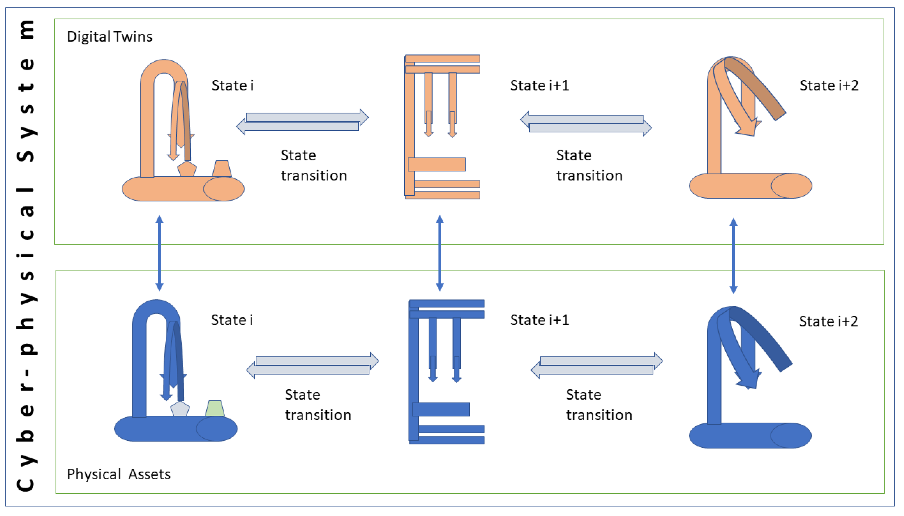
  • Digital Twin—in contrast to a digital shadow, the automated data flow is bidirectional, and thus a change in the status of the digital object also results in a change of status in the physical object [28].
Each of the selected in-depth sources for this study describes models and concepts that can be assigned to the category Digital Twin from the list above. Based on this classification, the cross-domain model considers Digital Twin development in the sense of the above given concept (according to [28])—it targets the dynamic coupling of physical and digital objects through automated bidirectional data flows.
The overarching DT development model is the formation of an integration to be applied for general purpose, so that it can be used for exploring to further domains. However, since the integrated development process contains domain-specific phases, it is advisable to start the development process with the selection of a domain-specific procedure—product lifecycle management, manufacturing, or predictive maintenance. Based on that domain-specific pre-selection, certain process steps are then skipped or additional process steps need to be executed to create a DT in the selected domain. For example, DT construction for manufacturing requires 3D CAD models. Hence, a corresponding step needs to be processed according to the manufacturing DT development model. It could not be taken from any other source or domain.
An essential property of the DT development model is that the represented process does not terminate after the execution of all steps, but continues cyclically. The reason for this is rooted in the characteristic of DTs, since the virtual model is continuously developed further and the corresponding changes are incorporated into the physical object. According to the findings from the relevant literature, the DT is not only continuously evolving, but may also require an adaptation of the general design or development of the underlying system. Thus, it is not a determinant process, but rather a cyclic procedure.
When merging the DT development models of the different domains into a single model, neither further abstraction nor concretization was required, since modeling the process steps at a certain level of abstraction was already taken into consideration during the creation of models for each of the domain categories. In the following we discuss the major steps of the DT development model and refer to the inputs from each of the domain models.
After the lead domain of the DT that is to be developed has been selected in the first step, the next step is the design subprocess, which differs depending on the domain. The goal of this subprocess is to create the virtual representation of the physical counterpart. In case the DT is a predictive maintenance DT, the following process steps need to be executed in sequence:
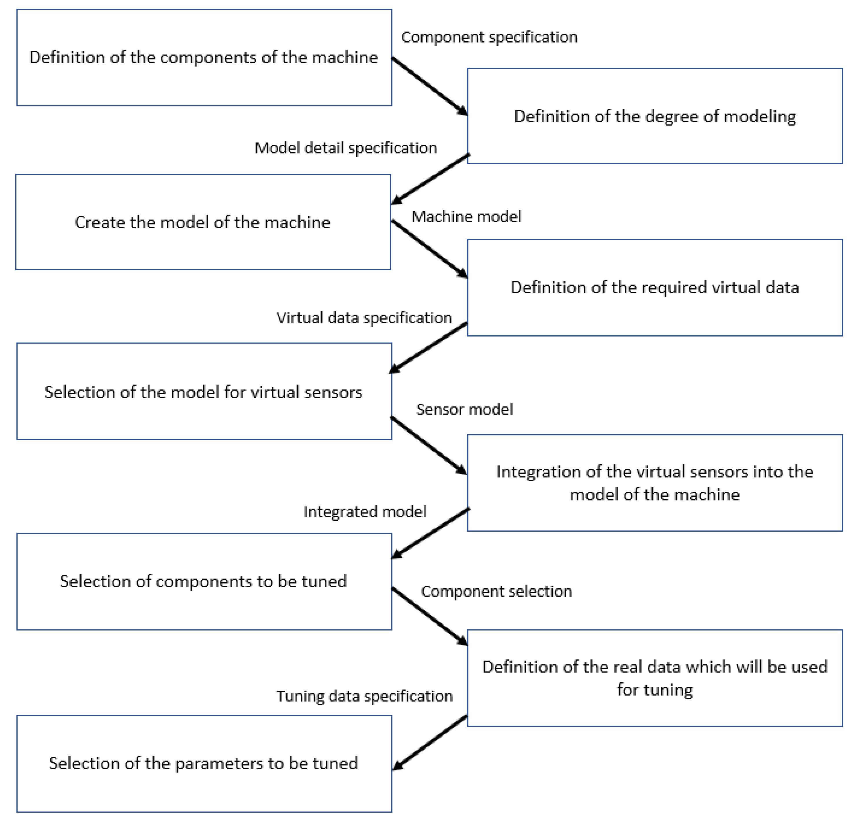
  • Definition of the components of the machine;
  • Definition of the degree of modeling;
  • Creating the model of the machine.
For the PLM domain, two different design procedures could be derived from the literature, variant 1 according to [9], and variant 2 according to [8]—see Section 4.1. The design process of the DT for the manufacturing domain consists of five process steps. In the first step, 3D CAD (Computer-Aided Design) models of the mechanical components are created. Then, these 3D CAD models are instantiated in parallel, and the functional groups and mechanical dependencies are created. In the last step, the completed 3D model is maintained in a data base.
The aim of the next sub-process is to develop the DT based on the previously defined design. This process again differs significantly from domain to domain. If the DT belongs to the predictive maintenance domain, the following tasks need to be performed in sequence:
  • Definition of the required virtual data;
  • Selection of the model for virtual sensors;
  • Integration of the virtual sensors into the model of the machine.
If a DT is created as part of a product life cycle, the data need to be analyzed, integrated, and visualized. Specifically, the steps of collecting data, analyzing data, integrating data, and visualizing data must be performed. Finally, the virtual representation of the product is created. If it is a manufacturing DT, the first step is to develop a digital model based on the 3D CAD model saved in the design process. Then the input and output signals, control functions, controllers and functional groups are created. Finally, the signal and function blocks are transferred for further evaluation, and finally the PLC control programs are worked out.
For the product lifecycle management and manufacturing categories, three process steps are each performed in the Verify and Validate subprocess. For product lifecycle DTs, the simulation of the product behavior in the virtual environment is done first, then the behavior of the physical product is controlled, and in the last step the real-time connection between physical and virtual product is created. For manufacturing DTs, the PLC (Programable Logic Controller) programs are tested in a virtual test run. The different models are then integrated into a single one which is also evaluated by test runs in the last step.
In the Deploy stage, the fully developed and verified DT is installed and configured for use. Subsequently, the following steps are to be performed for DTs for predictive maintenance:
  • Selection of the components to be coordinated with each other;
  • Definition of the real data;
  • Selection of the parameters that are to be matched.
The DT can be used productively once all the process steps described above have been completed. The literature shows that product-relevant data is continuously collected in the area of product lifecycle management.
In the Evaluate step, it is confirmed whether the DT delivers the intended benefit in a sufficient way with reference to the goal and metric. If this is the case, the DT can be used further. In this case, the next process step is Use again. If this is not the case, the DT management system must be maintained, and Maintain must be executed as the next process step.
If the adjustment is minor, the existing model can be developed further in certain cases and the Tune process step is carried out. If the model needs to be revised, the Rebuild process step follows. If the basic design has to be revised, the next step is Subprocess Design. If the existing design can be used further, the process continues with the Develop subprocess.
Since the integrated DT development process model is too large for an inclusion of the overall picture, it is presented as set of sub processes in Figure 10 and partially detailed in Figure 11 and Figure 12. The DT development model has been specified in an enriched BPMN (https://www.bpmn.org/, accessed on 30 June 2022), validated and executed with the Camunda platform (https://camunda.com, accessed on 30 June 2022).
The current version of the integrated DT development model is under evaluation. The pilot use case concerns a dispatching unit as part of a smart logistics process including a CPS. It concerns the transportation of critical goods, such as vaccines to be distributed from some storage location to a vaccine center. The dispatching unit is based on a CPS to implement packaging and transport requirements based on a specific order.
We can assume the vaccine being delivered to the dispatching station with (order) information on what needs to be taken into account for its transportation, such as positioning in a transportation box and cooling. The dispatching unit has the task to package the vaccine in a transportation box fitting to the order and transportation requirements, so it can be picked up by a delivery service.
Once the vaccines are received by the dispatching station, a robot carries it to a dispatching bench monitored by sensors to ensure that proper temperature conditions are met. There, the vaccine is packaged using storage containers that can be equipped with IoT devices to ensure the transportation requirements are satisfied. A robot system equips the transportation container according to the transportation requirements and puts the vaccine into the container before carrying it to a pick-up place once the transport can start.
As the use case qualifies for DT development in terms of digital threads, the integrated DT development model can be applied as follows. The first step of applying the DT development model requires to check whether a domain-specific set-up procedure can be followed. For the smart transportation case it is possible to follow the development procedure due to the high level of abstraction of the developed integrated DT development model. The smart transportation use case can be handled close to the manufacturing procedure for Prepare, Design, and Verify/Validate.
In the following we provide the results on the level of identified subprocesses as defined in Figure 10.
  • Prepare includes not only a use case description as provided above, but also the collected inputs to develop a DT. For the transportation case, the major rationale was the objective of designing all devices in way that a minimum of stationary equipment and information for dispatching is required, so that the process can be applied in various physical settings, and thus does not require a certain physical environment. The goods and devices should ‘carry’ all process-relevant information to trigger the next step. For instance, the vaccine to be dispatched contains information under which conditions it needs to be transported.
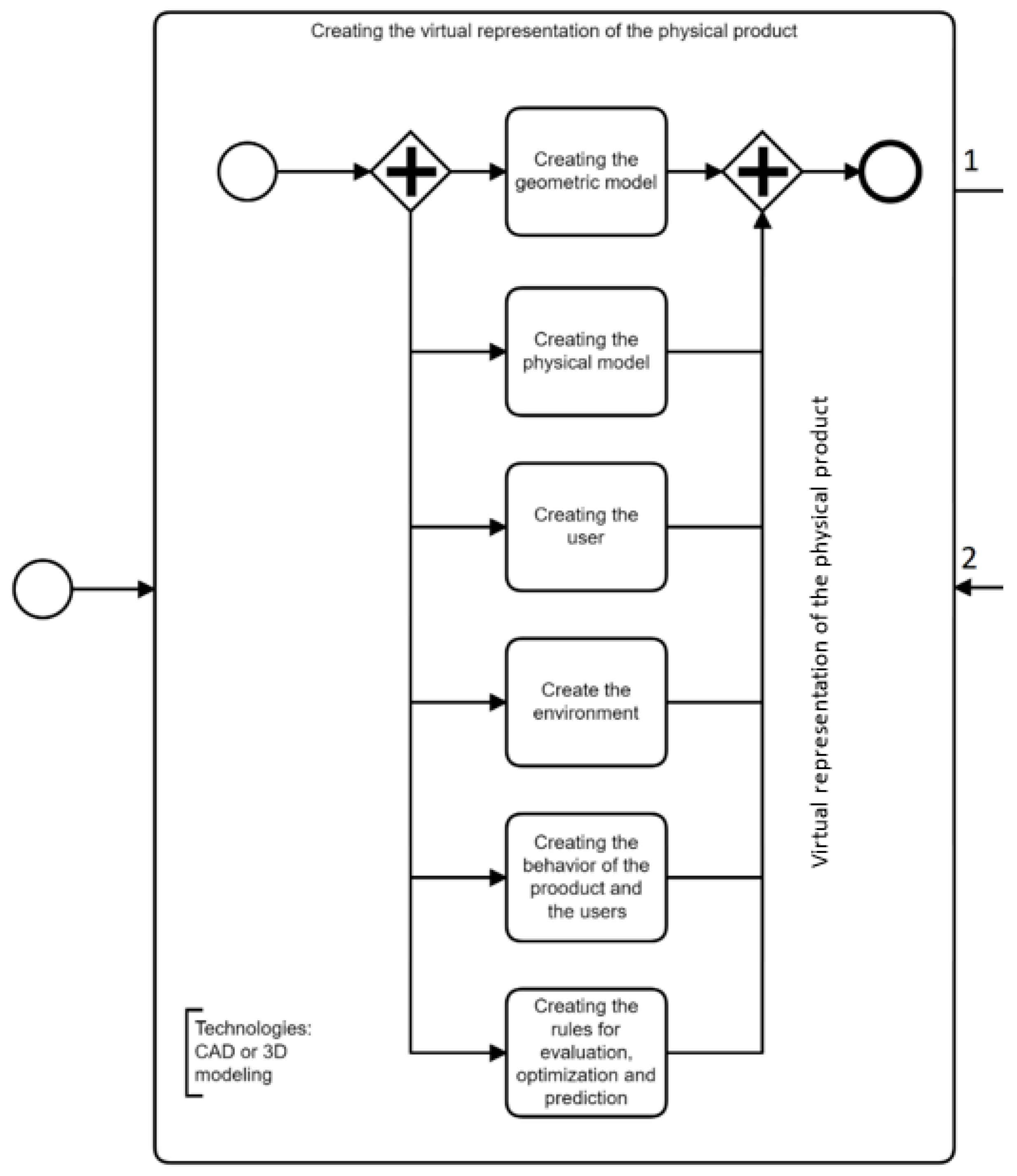
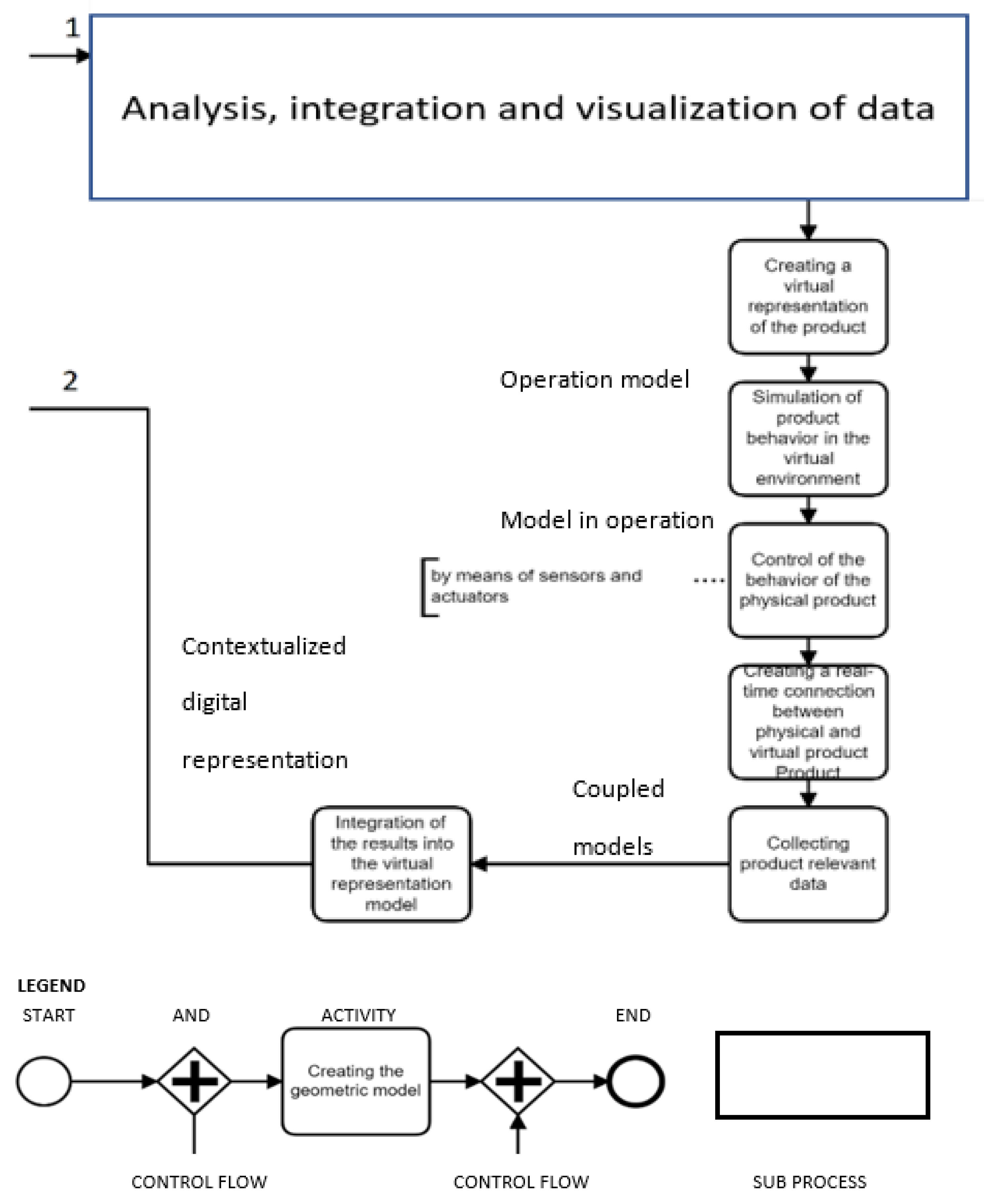
  • Design: In this step the virtual representations of the physical counterparts is modeled following the procedure of manufacturing DT design. For equipping containers with IoT systems to transport vaccines as required, 3D CAD models of the mechanical part to plug in sensors into container are created. In addition, the storage system for containers and IoT systems is constructed. Finally, these 3D CAD need to be instantiated to identify the mutual interaction and functional dependencies. The final step includes the completion of a 3D model including the three models. These models lay the groundwork for developing the DT including the business logic required to operate the CPS. All incoming and outgoing message, control functions, and functional groups are specified in this step. It includes abstractions for the robot movements to accomplish packaging after picking up the vaccine.
  • Verify/Validate targets the CPS behavior for the entire dispatching procedure, including testing its components in a virtual test run. Of particular importance is the interaction between component to accomplish the packaging task. The different behavior models are integrated into a network of processes.
  • Deploy: The fully developed and validated DT becomes part of the transportation workflow and can be installed and configured for practical use. For each component, a corresponding runtime needs to be set up and successively integrated with the other components to successfully enable the required interaction for picking up and packaging. The transportation case also requires synchronization, which means to couple the physical devices with their digital counterpart at runtime.
  • Use: Once the DT can be used to control the dispatching process involving the physical CPS components (robotic system fir picking up the vaccine and plug in IoT system devices, container, IoT systems).
  • Evaluate: When in use, the DT operation is evaluated in terms of successfully picking up the vaccine by the robot system, equipping a container with the required IoT systems, and packaging the vaccine for further transportation. Adaptation might be required in case of adjusting components, changes in the physical handling, or the logic to handle the business case. In this case, the DT management must be maintained.
  • Tune: If the adjustment is minor, the existing DT model can be changed during runtime. In other cases, the DT model changes lead to the redesigning of the CPS structure and/or component behavior of the transportation components.
  • Rebuild: Changing requirements or faulty behavior can lead to a total DT revision, affecting the transportation workflow and its structure (including physical components). For instance, the distribution of information and IoT devices could be affected if dispatching information is not located on the vaccine to be packaged and/or IoT systems need to be composed and tested before being plugged into the container.

5. Discussion

The aim of this study was to investigate procedures for the development of DTs based on empirical in-depth studies and to put it into the context of existing DT concepts. It turns out that, although the basic DT concept and operation of DTs have already been addressed in several studies, empirical reports as targeted in this study provide only limited insight into underlying development steps and role understanding in development.
Our analysis of the in-depth studies in DT development reveals that there are still no uniform, generally applicable DT development models. However, the presented level of abstract specification allows the various approaches for developing and refining DTs stemming from different domains to be integrated in an integrated DT development model. Hence, two research questions addressed in this work can be answered as follows.
  • What empirically valid knowledge exists (in different application domains) about the process for developing DTs?
By means of a literature search, fifteen sources were selected that detailed the experiences in the creation and further development of DTs. While the concepts described therein did not allow for straightforward process integration and aligned variants of development, they did allow for domain-specific categorization: product lifecycle management, manufacturing, and predictive maintenance. For each of these categories, an integrated DT development model could be specified based on the literature.
It captures DT development roles, activities, input and output data, as well as the sequence of activities to create and further develop a DT. Accordingly, the first research question could be answered in terms of a consolidated analysis comprising basic steps and workflows for the creation and further development of DTs. However, the specification of most of the generated and processed data (describing the structure and content of DTs) and stakeholder roles specified in the domain-specific development models has been based on information provided implicitly by the in-depth study authors.
  • In how far can a generally applicable model be defined for the construction and further development of DTs?
To answer this research question, the first step was to analyze which DT category is concerned with the domain-specific development models, in order to check whether the captured domain models target the same type of DT. Since all in-depth studies were targeting the synchronized, dynamic coupling of physical and digital twins, the approaches could be integrated without differentiating the type of DT twin to be developed.
With respect to cross-domain development, it could be shown that the process steps differ in part from domain to domain for the studied domains (Product Lifecycle Management, manufacturing, and predictive maintenance). Hence, when applying the integrated development model, an initial selection of a development variant of one of these domains is currently required. It concerns the preparation and design phase of DT development. The subsequent steps, ranging from deployment to rebuilding DTs, have been found to be domain-independent DT development steps. They represent a general frame of reference for DT deployment, use, and further development.
Although we could demonstrate the application of the proposed integrated DT development model for a transportation use case, further research is required to consolidate the findings. Since the analysis of the published in-depth studies revealed mainly implicit information with respect to technical development roles and the structure of DTs, further studies need to explore the skill sets and structural constituents of DTs to develop a detailed understanding of developer and consumer roles, including their needs to manage the DT development process.

6. Conclusions

Recognizing the demand for a model detailing major stakeholder roles and tasks along fundamental development steps, we could identify and select valid empirical studies to define a unifying model across DT application domains. The challenges we had to meet were:
  • to identify relevant roles and processed information from the empirical data
  • to determine the proper level of abstraction, both for domain-specific modeling, and for providing a frame of reference for further DT developments
Although we could meet the objectives of this study in terms of capturing relevant information sources, representing it in contextual process models, and testing their applicability in another domain, further studies need to be performed to explore the full potential of the presented results.

Author Contributions

Conceptualization: W.H. and C.S.; methodology, W.H. and C.S.; software, W.H.; validation, W.H. and C.S.; formal analysis, W.H.; data curation, W.H. and C.S.; writing—original draft preparation, W.H.; writing—review and editing, W.H. and C.S.; visualization, W.H. and C.S.; supervision, C.S. All authors have read and agreed to the published version of the manuscript.

Funding

This research received no external funding.

Institutional Review Board Statement

Not applicable.

Informed Consent Statement

Not applicable.

Data Availability Statement

Not applicable.

Acknowledgments

The support of JKU master students providing referential support is acknowledged.

Conflicts of Interest

The authors declare that they have no conflict of interest.

Glossary

Digital TwinA digital twin is a digital representation of a physical asset
ProcessA process describes a value-generating procedure in terms of actors or systems that perform activities in a sequential and logical order, while processing data, in order to accomplish a business-relevant task or objective
StakeholderA stakeholder is a person in a specific role involved in the development and/or operation of system or process
DomainA domain is an application sector of Cyber-Physical Systems
Cyber-Physical SystemA cyber-physical system is a socio-technical system composed of information technology and physical elements. These components are connected and have the capability to exchange data, in order to control the system’s operation via a network, such as the Internet
Internet-of-ThingsThe Internet-of-Things denotes interconnected computing devices via an Internet communication protocol. The devices can thus exchange data
Socio-technical SystemA socio-technical system is a system involving people and technology. It comprises individuals, communities, digital and physical technologies. Humans interact with these technologies to accomplish their tasks and adapt them according to their needs

References

  1. Sauer, O. The Digital Twin-An Essential Key Technology for Industrie 4.0. ERCIM News 2018, 32–33. [Google Scholar]
  2. Glaessgen, E.; Stargel, D. The Digital Twin Paradigm for Future NASA and U.S. Air Force Vehicles. In Proceedings of the 53rd AIAA/ASME/ASCE/AHS/ASC Structures, Structural Dynamics and Materials Conference, Honolulu, HI, USA, 23–26 April 2012; American Institute of Aeronautics and Astronautics: Reston, VA, USA, 2012. [Google Scholar] [CrossRef]
  3. Grieves, M. Origins of the Digital Twin Concept; Florida Institute of Technology: Melbourne, FL, USA, 2016. [Google Scholar] [CrossRef]
  4. Jones, D.; Snider, C.; Nassehi, A.; Yon, J.; Hicks, B. Characterising the Digital Twin: A systematic literature review. CIRP J. Manuf. Sci. Technol. 2020, 29, 36–52. [Google Scholar] [CrossRef]
  5. Lu, Y.; Liu, C.; Kevin, I.; Wang, K.; Huang, H.; Xu, X. Digital Twin-driven smart manufacturing: Connotation, reference model, applications and research issues. Robot. Comput.-Integr. Manuf. 2020, 61, 101837. [Google Scholar] [CrossRef]
  6. Rasheed, A.; San, O.; Kvamsdal, T. Digital twin: Values, challenges and enablers from a modeling perspective. IEEE Access 2020, 8, 21980–22012. [Google Scholar] [CrossRef]
  7. Liu, M.; Fang, S.; Dong, H.; Xu, C. Review of digital twin about concepts, technologies, and industrial applications. J. Manuf. Syst. 2021, 58, 346–361. [Google Scholar] [CrossRef]
  8. Tao, F.; Zhang, H.; Liu, A.; Nee, A.Y.C. Digital Twin in Industry: State-of-the-Art. IEEE Trans. Ind. Inform. 2019, 15, 2405–2415. [Google Scholar] [CrossRef]
  9. Zheng, Y.; Yang, S.; Cheng, H. An application framework of digital twin and its case study. J. Ambient Intell. Humaniz. Comput. 2019, 10, 1141–1153. [Google Scholar] [CrossRef]
  10. Negri, E.; Fumagalli, L.; Macchi, M. A review of the roles of digital twin in cps-based production systems. Procedia Manuf. 2017, 11, 939–948. [Google Scholar] [CrossRef]
  11. Moyne, J.; Qamsane, Y.; Balta, E.C.; Kovalenko, I.; Faris, J.; Barton, K.; Tilbury, D.M. A Requirements Driven Digital Twin Framework: Specification and Opportunities. IEEE Access 2020, 8, 107781–107801. [Google Scholar] [CrossRef]
  12. Tao, F.; Sui, F.; Liu, A.; Qi, Q.; Zhang, M.; Song, B.; Guo, Z.; Lu, S.C.-Y.; Nee AY, C. Digital twin-driven product design framework. Int. J. Prod. Res. 2019, 57, 3935–3953. [Google Scholar] [CrossRef]
  13. Tao, F.; Cheng, J.; Qi, Q.; Zhang, M.; Zhang, H.; Sui, F. Digital twin-driven product design, manufacturing and service with big data. Int. J. Adv. Manuf. Technol. 2018, 94, 3563–3576. [Google Scholar] [CrossRef]
  14. Lim KY, H.; Zheng, P.; Chen, C.-H. A state-of-the-art survey of Digital Twin: Techniques, engineering product lifecycle management and business innovation perspectives. J. Intell. Manuf. 2020, 31, 1313–1337. [Google Scholar] [CrossRef]
  15. Haag, S.; Anderl, R. Digital twin—Proof of concept. Manuf. Lett. 2018, 15, 64–66. [Google Scholar] [CrossRef]
  16. Park, K.T.; Nam, Y.W.; Lee, H.S.; Im, S.J.; Noh, S.D.; Son, J.Y.; Kim, H. Design and implementation of a digital twin application for a connected micro smart factory. Int. J. Comput. Integr. Manuf. 2019, 32, 596–614. [Google Scholar] [CrossRef]
  17. Kong, T.; Hu, T.; Zhou, T.; Ye, Y. Data Construction Method for the Applications of Workshop Digital Twin System. J. Manuf. Syst. 2021, 58, 323–328. [Google Scholar] [CrossRef]
  18. Wang, K.-J.; Lee, Y.-H.; Angelica, S. Digital twin design for real-time monitoring—A case study of die cutting machine. Int. J. Prod. Res. 2021, 59, 6471–6485. [Google Scholar] [CrossRef]
  19. Stark, R.; Fresemann, C.; Lindow, K. Development and operation of Digital Twins for technical systems and services. CIRP Ann. 2019, 68, 129–132. [Google Scholar] [CrossRef]
  20. Deb, A. Crashworthiness design issues for lightweight vehicles. In Materials, Design and Manufacturing for Lightweight Vehicles; Elsevier: Amsterdam, The Netherlands, 2010; pp. 332–356. [Google Scholar] [CrossRef]
  21. Biesinger, F.; Meike, D.; Kraß, B.; Weyrich, M. A digital twin for production planning based on cyber-physical systems: A Case Study for a Cyber-Physical System-Based Creation of a Digital Twin. Procedia CIRP 2019, 79, 355–360. [Google Scholar] [CrossRef]
  22. Ashtari Talkhestani, B.; Weyrich, M. Digital Twin of manufacturing systems: A case study on increasing the efficiency of reconfiguration. Automatisierungstechnik 2020, 68, 435–444. [Google Scholar] [CrossRef]
  23. Centomo, S.; Dall’Ora, N.; Fummi, F. The Design of a Digital-Twin for Predictive Maintenance. In Proceedings of the 25th IEEE International Conference on Emerging Technologies and Factory Automation (ETFA), Vienna, Austria, 8–11 September 2020; pp. 1781–1788. [Google Scholar] [CrossRef]
  24. Aivaliotis, P.; Georgoulias, K.; Chryssolouris, G. The use of Digital Twin for predictive maintenance in manufacturing. Int. J. Comput. Integr. Manuf. 2019, 32, 1067–1080. [Google Scholar] [CrossRef]
  25. Aivaliotis, P.; Georgoulias, K.; Arkouli, Z.; Makris, S. Methodology for enabling Digital Twin using advanced physics-based modelling in predictive maintenance. Procedia CIRP 2019, 81, 417–422. [Google Scholar] [CrossRef]
  26. Aheleroff, S.; Xu, X.; Zhong, R.Y.; Lu, Y. Digital Twin as a Service (DTaaS) in Industry 4.0: An Architecture Reference Model. Adv. Eng. Inform. 2021, 47, 101225. [Google Scholar] [CrossRef]
  27. Barricelli, B.R.; Casiraghi, E.; Fogli, D. A Survey on Digital Twin: Definitions, Characteristics, Applications, and Design Implications. IEEE Access 2019, 7, 167653–167671. [Google Scholar] [CrossRef]
  28. Kritzinger, W.; Karner, M.; Traar, G.; Henjes, J.; Sihn, W. Digital Twin in manufacturing: A categorical literature review and classification. IFAC-PapersOnLine 2018, 51, 1016–1022. [Google Scholar] [CrossRef]
Figure 1. Digital twins and corresponding physical assets in cyber-physical settings in line with [5].
Processes 10 01490 g001
Figure 2. Digital Twinning in line with [5].
Processes 10 01490 g002
Figure 3. Model development process based on selected in-depth studies.
Processes 10 01490 g003
Figure 4. The sequence of steps (i.e., process model) of Product Lifecycle Management for implementing a product life cycle, specified in an enriched Business Process Model & Notation (BPMN) (https://www.bpmn.org/ accessed on 30 June 2022), data derived from [9].
Processes 10 01490 g004
Figure 5. Sequence of steps (i.e., process) for developing a PLM-DT derived from [13], specified in an enriched BPMN (https://www.bpmn.org/, accessed on 30 June 2022).
Processes 10 01490 g005aProcesses 10 01490 g005b
Figure 6. (a). Sequence of steps for domain-specific DT development model in PLM for subprocess ‘Creation of a virtual product representation’. (b). Sequence of steps for domain-specific DT development model in PLM for subprocess 2 (Analysis, integration and visualization of data), (c) further processing. Data of variant 1 as described in [9], data of variant 2 as described in [8].
Processes 10 01490 g006aProcesses 10 01490 g006bProcesses 10 01490 g006c
Figure 7. Sequence of steps for DT development model derived from [11] Green: off-line, yellow: on-line activity.
Processes 10 01490 g007
Figure 8. Sequence of steps for DT design, development, verification/validation, deployment and operation in manufacturing.
Processes 10 01490 g008aProcesses 10 01490 g008b
Figure 9. Sequence of domain-specific development sub-processes for predictive maintenance.
Processes 10 01490 g009
Figure 10. Sub-processes of integrated DT development model.
Processes 10 01490 g010
Figure 11. ‘Verify/Validate and Deploy’ subprocess of the integrated DT development model.
Processes 10 01490 g011aProcesses 10 01490 g011b
Figure 12. Use and further development subprocess of integrated DT development model.
Processes 10 01490 g012
Table 1. Results when searching for empirical evidence concerning structured DT development.
Search No.DatabaseSearch Terms Including Designation and Link
Sources from 2014
Number of Entries FoundNote
1Google Scholardigital twin AND “product”12,1003 in-depth sources selected
2Google Scholardigital twin AND “implementation” AND “case study”17,2007 in-depth sources selected
3Google Scholardigital twin AND “tuning”21100 Sources selected
4Google Scholar“case study” AND “digital twin” AND “tuning”8592 in-depth sources selected
5Google Scholarcase study AND “digital twin” AND “learning”51500 Sources selected
6Google Scholarcase study AND “digital twin” AND “improvement”67100 Sources selected
7Google Scholarcase study AND “digital twin” AND “lifecycle”49502 in-depth sources selected
8Google Scholarcase study AND “digital twin” AND “validation”62101 in-depth sources selected
Table 2. Selected in-depth studies on the development of DTs in domain context.
Product-Lifecycle ManagementManufacturingPredictive MaintenanceIndepth StudyYear
x An application framework of Digital Twin and its case study [9]2019
x Digital twin-driven product design framework [12]2019
x Digital twin-driven product design, manufacturing and service with big data [13]2018
x A state-of-the-art survey of Digital Twin: techniques, engineering product lifecycle management and business innovation perspective [14]2020
x Digital Twin—proof of concept [15]2018
x Design and implementation of a Digital Twin application for a connected micro smart factory [16]2019
x Data construction method for the application of workshop Digital Twin system [17]2020
x Digital Twin design for real-time monitoring—a case study of die cutting machine [18]2020
x Development and operation of Digital Twin for technical systems and services [19]2019
x A Digital Twin for production planning based on Cyber-Physical Systems: A case study for a Cyber-Physical System-based creation of a Digital Twin [20,21]2019
x Digital Twin of manufacturing systems: a case study on increasing the efficiency of reconfiguration [22]2020
x Requirements-driven Digital Twin framework: Specification and opportunities [11]2020
xThe design of a Digital-Twin for predictive maintenance [23]2020
xMethodology for enabling Digital Twin using advanced physics-based modelling in predictive maintenance [24]2019
xThe use of Digital Twin for predictive maintenance in manufacturing [25]2019
Publisher’s Note: MDPI stays neutral with regard to jurisdictional claims in published maps and institutional affiliations.

