Article

Product-Property Guided Scale-Up of a Fluidized Bed Spray Granulation Process Using the CFD-DEM Method

by
Paul Kieckhefen
*,
Swantje Pietsch-Braune
and
Stefan Heinrich
Institute of Solids Process Engineering and Particle Technology, Hamburg University of Technology (TUHH), Denickestrasse 15, 21073 Hamburg, Germany
*
Author to whom correspondence should be addressed.
Processes 2022, 10(7), 1291; https://doi.org/10.3390/pr10071291
Submission received: 11 June 2022 / Revised: 26 June 2022 / Accepted: 27 June 2022 / Published: 30 June 2022
(This article belongs to the Special Issue Computational and Experimental Study of Granulation in Fluidized Beds)

Abstract

:
In this work, a method to predict the surface structures of particles produced by fluidized bed spray layering granulation using the CFD-DEM method was developed. A simple state-variable/event tracking approach was implemented to capture indirect quantifiers of the progression of structure-forming microprocesses. The state of the droplet at the time of impact on the particle surface, as well as the time required for drying, is correlated to product properties that quantify surface structure morphology such as roughness. A workflow for scale-up of fluidized bed granulation guided by product-property predictors is presented. The approach was tested on a demonstration case from the literature, where a particle core is coated with sodium benzoate solution. The experiment was scaled-up by a factor of eight to pilot-scale using the developed method. Varying the number of nozzles in use in the pilot-scale granulation affected the particle surface roughness due to the differing drying conditions encountered. On this basis, the ability of the tracked-quantity approach to capture the relationship between product properties and geometric feature or process conditions is demonstrated.

1. Introduction

Fluidized beds consist of a particulate bulk that is vertically permeated by gas that causes the particles to fluidize, inducing mixing and excellent heat and mass transfer. Fluidized bed spray granulation is a process where a solids-containing liquid phase is introduced into such a fluidized bed to facilitate particle growth. Two modes of operations can be distinguished:
  • Layering granulation, where particles quickly dry and the injected liquid leaves a solid residue that forms a shell or coating, and 
  • agglomeration, where the cohesive forces of the liquid cause the particles to remain in contact, resulting in the formation of larger granules after solidification of the liquid or sintering.
Experimental studies in this area were performed by Hoffmann et al. [1], Rieck et al. [2] and Schmidt et al. [3].
Hoffmann et al. [1] and Rieck et al. [2] studied the deposition of soluble salts (sodium benzoate) on particle cores that are made of either silica glass or alumina ( γ - Al 2 O 3 ). They varied the solution spray rate and fluidization air temperature in batch granulation experiments and analyzed the porosity of the deposited salt layer using micro-computer tomography ( μ -CT). A linear correlation between the drying potential of the inflowing fluidization air and the resulting layer porosity was identified.
Schmidt et al. [3] performed similar experiments using a suspension of solid fines as a spraying liquid and varied (1) the atomization pressure, (2) the fluidization air temperature and (3) the spray rate.
Diez et al. [4] performed continuous granulation experiments in a pilot-scale fluidized bed spray granulator equipped with a mill-sieve cycle. This allowed for the production of granules whose entire structure was generated using the process conditions in the granulator. They analyzed
  • the product moisture content,
  • the area surface roughness as analyzed by confocal microscopy,
  • the modulus of elasticity using compression testing,
  • the granule porosity using X-ray micro-computer tomography,
  • the wetting behavior using the contact angle as given by the sessile drop experiment.
The operating point with respect to gas mass flow rate was kept constant while varying spray rate and air temperature to capture the effect of the drying potential. The overall results fit with the findings of Schmidt et al. and Hoffmann et al.: Granule porosity increases for wetter drying conditions, equating to higher spray rates, lower drying potentials and lower temperatures. As this study considered actual target properties such as compression strength and wetting behavior as well, it is of great interest for this work. All of the relationships between these and the porosity behave as expected—compression strength increases with harsher drying conditions (= high drying potential), wetting behavior improves with wetter drying conditions due to increasing surface roughness/porosity.
Another recent study demonstrating the accuracy of the CFD-DEM method for modeling particulate flows is that of Batista et al. [5] who demonstrated the ability of the method to reproduce the minimum spouting velocity curve of a conical lab-scale spouted bed for Sorghum grains. Of interest with respect to CFD-DEM modeling of agglomeration is the work of Bahramian and Olazar [6] in which they identify cohesion model-normal force model combinations that are able to reproduce agglomerate formation as well as macroscopic process quantifiers such as the pressure drop of a conical lab-scale fluidized bed with titania nanoparticles.
Other studies focus on agglomeration of primary particles into agglomerates—the physics involved there do not apply for layering granulation/coating and are thus not considered here.
First, we will give an overview of the implementation of heat and mass transfer in the CFD-DEM method used for the simulation of spray granulation. The concept of tracked quantities is introduced, as well as the method that is used to correlate the tracked quantities with product properties from the laboratory-scale calibration experiments. The setup for the experiments and the simulations are then outlined and in final content section, and the resulting tracked quantity-product property mapping is presented and applied to the pilot-scale case.

2. Materials and Methods

In this section, the CFD-DEM method is outlined to the degree that is required for the description of the dynamics of fluidized bed spray granulators and the tracked property approach for connecting micro-scale process descriptors to the properties of the product they cause. For a more in-depth explanation, please refer to Kieckhefen et al. [7].

2.1. CFD-DEM Simulation

The CFD-DEM method combines the ability of the discrete element method (DEM) to describe a granular system as a set of point masses with the capability of computational fluid dynamics (CFD) to describe the fluid phase in which the particles are contained, as well as their interactions. A more expansive overview of the particularities in this method is given in by Golshan et al. [8] and Kieckhefen et al. [9].
For the description of fluidized bed spray granulation, this method has to be extended to consider
  • droplet injection and transport in the gas phase,
  • droplet evaporation,
  • deposition of droplets onto the particle surface,
  • evaporation of liquid on the particle surface,
  • transport of energy/enthalpy in the gas phase and
  • transport of a vapor species in the gas phase.
For this work, the CFDEMcoupling framework [10] was used as a foundation, in particular the cfdemSolverChem by Kinaci et al. [11] that considers heat and species transport in an implicit manner. The details of their implementation can be found in those respective publications. Another Lagrangian phase to represent the droplets was introduced using functionality from the sprayFoam solver of OpenFOAM. The detail of their grid-based deposition onto particles is given in the work of Kieckhefen et al. [12].
Evaporation occurs in the context of three different control volumes, namely the gas phase ( g ), the solid particle phase ( p ) as well as the droplets ( d ). The focus is therefore on their interactions driven by evaporation and heat exchange, and formulating their differential heat and mass balances.
The vapor mass source term for the gaseous phase is given by
d M g d t = i M ˙ s g , i evap + j M ˙ d g , j evap
where M g refers to the mass of vapor in a control volume, M ˙ s g , i evap is the vapor mass flow emitted by the surface liquid of a single particle i into the gas phase and M ˙ d g , j evap is the respective vapor mass flow emitted by a single droplet j into the gas phase. The corresponding change in internal energy or enthalpy due to the process of evaporation, referred to summarily by E g or energy, is given by
d E g d t = i ( E ˙ p g , i evap + Q ˙ p g , i + j ( E ˙ d g , j evap + Q ˙ d g j ) ,
where for any given particle i, the enthalpy flow to the gas phase due to evaporation is given by E ˙ p g , i evap , the heat exchanged with the particle Q ˙ p g , i . Analogously, E ˙ d g , i evap represents the evaporative energy flow from a droplet j and Q ˙ d g , j the heat exchanged with said droplet.
For the particle, the change in energy E p , i has to be considered
d E p , i d t = E ˙ i dep E ˙ s g , i evap Q ˙ p g , i
where E ˙ i dep is the energy flow due to deposition of droplets. The mass of liquid on the particle’s surface M s is given by evaporation and deposition:
d M s , i d t = M ˙ i dep M ˙ s g , i evap .
The heat transfer correlation by Gunn et al. [13] was used for calculating the Nusselt number:
Nu = α d p k g = ( 7 10 α g + 5 α g 2 ) ( 1 + 0.7 Re 0.2 Pr 0.33 ) + ( 1.33 2.4 α g + 1.2 α g 2 ) Re 0.7 Pr 0.33
where Re = U rel ρ g / η g is the Reynolds number, d p is the particle diameter, U rel is the relative velocity, ρ g is the gas density and η g is the viscosity of the gas phase, α is the heat transfer coefficient, k g is the heat conductivity of the gas, Pr = c p , g η g / k g is the Prandtl number, c p , g is the heat capacity of the gas phase and α g the gas volume fraction. This correlation captures the swarm effect of other particles surrounding the particle considered for Reynolds numbers Re < 10 5 and solids volume fractions α p > 0.35 .
The heat flow from the gas to the particle i equates to
Q ˙ g p , i = Nu d p k g S ( T g T p , i )
where T g is the gas temperature and the particle temperature is represented by T p , i .
The evaporation rate M ˙ s g , i evap can be calculated using the analogy between heat and mass transfer. The analogy states that a heat transfer correlation, such as that given in Equation (5) by Gunn et al. [13], can be used for the calculation of the mass transfer coefficient β by substituting the Nusselt number Nu with the Sherwood number
Sh = β D d p ,
where D is the diffusion coefficient of the vapor species in the bulk and the Prandtl number Pr is substituted with the Schmidt number Sc = η g / ρ g D . From this, the evaporation rate of an individual particle can be calculated using:
M ˙ s g , i evap = Sh d p D S s , i φ wet , i ρ g ( y i * y i )
where S p = π d p 2 is the total particle surface area and the fraction of said area wetted by the liquid film, φ wet , i , is modeled by the asymptotic projection-area method [14]. The model by Karikuki et al. [14] assumes droplets wet their projection area A proj = π d d 2 / 4 , equating to an individual fractional coverage of f = A proj / S p = ( d d / 2 d p ) 2 . The areas of successive impacts are assumed to overlap with previous impacts with a probability of ( 1 f ) ( N 1 ) , with N 1 being the number of previous impacts. Thus, the wetted area fraction approaches a value of
φ wet , i = 1 ( 1 f ) N .
This is generalized to non-integer values of N by approximating the number of impacts as the ratio of surface liquid mass M i and the droplet mass M d = ρ d π d d / 6 :
N = M i / M d .
Vapor transport is realized by solving the scalar transport equation
( ρ g α g y i ) t + · ( ϕ y i ) = Δ ( α g ( η g + η g , t ) y i ) + S y i
where y i represents the vapor mass fraction in the gas phase, ϕ the superficial mass flux of the gas phase, η g , t is the turbulent viscosity and S y i is the sum of all source terms for y i . The species source term is composed of the contribution by the spray evaporation S y i spray and surface liquid evaporation S y i evap :
S y i = S y i spray + S y i evap
whereas the combustion source term is entirely explicit, the evaporation and spray parts include both explicit and implicit contributions. The remaining inert species y inert is solved for using the expression
y inert = 1 j inert y j .
Treating the inert species in any other way, i.e., solving a transport equation as well, would require normalization in the manner of
a = j y j
y i = y i a .
This, in turn, might violate mass conservation of individual species because this information is not reflected in the density/continuity equation. To conserve mass, a source term S ˙ ρ g is introduced into the density equation
( α g ρ g ) t + · ϕ = S ˙ ρ g .
This source term is composed of components for the spray mass source S ρ g spray and the evaporation mass source S ρ g evap :
S ρ g = S ρ g spray + S ρ g evap .
These terms are treated entirely explicitly within the pressure-loop due to the segregated treatment of systems of equations in OpenFOAM.
The Eulerian vapor species source term
S y i evap = j β j , s f A s , j ρ g ( y i * y i ) V = S y i evap , ex + S y i evap , im
for evaporation of surface liquid is split between an implicit term that depends on the current vapor mass fraction and contributes to the diagonal of the linear system
S y i evap , im = j β j , s f A s , j ρ g ( y i ) V
and an explicit component that instead appears on the right side:
S y i evap , ex = j β j , s f A s , j ρ g y i * V .
The consequence of this formulation is that the saturation vapor concentration is never exceeded as this would cause the source term to vanish. After solving these, the explicit Lagrangian mass sink M ˙ g p , evap is calculated. y is the gas phase vapor fraction and y i * the saturation vapor fraction in the gas phase, derived from an Antoine equation:
y i * = 10 5 × 10 A B T s , i + C Pa ρ g R m M w , vap T s , i
where R m = 8.314  J mol 1 K 1 is the molar gas constant, M vap is the molecular weight of the vapor species and T s , i the surface film temperature. For water, the Antoine equation coefficients are given by A = 4.6543 , B = 1435.264 K , C = 64.848 K , valid in the range of 255.9 K T 373 K , and the molecular weight M vap has a value of 0.01802   k g mol 1 , as given by Stull et al. [15].
For the implementation of heat transfer, refer to Kinaci et al. [11] or Lichtenegger et al. [16].

2.2. Tracked Quantities

The tracked quantities are of two distinct types, those that are per-particle and those that are per-event.
Per-particle quantities are scalar values or vectors associated with an individual particle, for example, a residence time in a specific region, or the temperature. Per-event quantities are calculated as they occur, such as the contact force in the case of particle collisions. Tracking many different per-particle properties will substantially slow down a simulation. They have to be kept in memory during the entire duration of the simulation and have to be written to disk for visualization or to create a checkpoint. This either requires stalling the simulation or spawning a thread that accesses the disk. As the quantity is present for every particle, this creates a great demand for disk storage space and working memory in the computer used—one double precision floating point number for every particle in the system in the case of scalars. Even for particles that are, for example, not wetted, this information is written to disk and kept in memory while not immediately contributing to the statistics. Simulation performance will decrease as these quantities have to be communicated when crossing from one processor’s simulation domain to another one, creating parallelization overhead. As they incur both a performance penalty and demand a lot of storage space, per-particle properties should be chosen sparingly with care.
In contrast, an almost arbitrary number of per-event quantities can be recorded. For these, data can be written to disk for every relevant event as it occurs, specific to the quantity and to the event that is tracked. For this reason, per-event quantities should be preferred over per-particle quantities.
For the category of per-particle quantities, tracking the lifetime of the liquid film on the particle surface is an obvious choice in fluidized bed spray granulation. The duration a liquid film is present should, in theory, be able to capture the interplay of evaporation, imbibition/dissolution and spreading. It also correlates to the kinetics of crystallization of soluble components of the liquid film.
As for per-event properties, the following properties should be tracked:
  • Solids concentration in the droplets at impact: The concentration of the solid component of droplets upon impact is an indicator for the intensity of the drying conditions that occur—determining interplay of solvent removal and aggregation of the solid components by diffusion, relating to the time available for nucleation and crystallization to occur for solutions and aggregation to take place in the case of suspensions.
  • Relative velocity at impact: The relative velocity between particle and droplet, together with viscosity and surface tension (both dependent on solids concentration), should correlate with the droplet interaction regime.

2.3. Product-Property Tracked Quantity Correlation

For recording the tracked quantities, a choice with regard to the further processing has to be made:
  • Population-based: Distributions over all tracked quantities are analyzed separately. This has the key advantage of being easily automated and taking into consideration the spread of the entire population of particles.
  • Particle-based: For single or selected particle populations, tracked quantities are correlated with each other to give a temporal sequence of events or states in which the particle is, e.g., periods of drying alternating with wetting. While this may be more intuitive to analyze, automatically scaling this analysis to the entire particle population is much more difficult.
In this work, the tracked quantities are evaluated on population bases. A priori, this should be acceptable when the product itself is homogeneous due to the mixing time in the apparatus being much smaller than the process time, allowing for every particle to experience similar wetting and drying cycles.
Mathematically speaking, the set of tracked quantities resulting from a simulation for an operating point a can be described as { X m , X n , } a where X m = { X i m } is an individual per-event value, the subscripts i , j , are indices counting over each respective tracked event and the superscripts m , n , refer to the kind of event that occurs. The resulting experimentally obtained product property from the corresponding process conditions in a is referred to as y a .
A mapping f ( { X m , X n , } a ) y a is therefore to be derived. The distribution of any of the tracked quantities { { X i m } , { X j n } , } a for each simulation has to be reduced to a set of descriptive statistical quantifiers. This can be either a set of percentiles or statistical moments, most prominently of which are the mean μ 0 ( X ) , the variance μ 1 ( X ) and the skewness μ 2 ( X ) (which is shown in its most simple form without normalization):
μ 0 X m = 1 N i events i N i X i m
μ 1 X m = 1 N i events i N i X i m μ 0 X m 2
μ 2 X m = 1 N i events i N i X i m μ 0 X m 3
where N i is the number of events of type m that were tracked. The result is a set M a of scalar statistical quantifiers for each simulation:
M a = { μ 0 X m , μ 1 X m μ 2 X m , μ 0 X n , μ 1 X n μ 2 X n } .
After transforming each of the distributions to a set of percentiles and/or statistical moments, a relation f ^ ( M a ) y a can be attempted using a linear function:
f ^ ( M ) = M · α + y 0 .
Subsequently, the data are normalized by subtracting the mean value of the distribution and dividing by its standard deviation. This becomes important when feature selection using L 1 regularization is introduced. The coefficients α and the intercept y 0 can be determined using the least-squares method that minimizes the objective function
g ( α , y 0 ) = process conditions a M a · α + y 0 y a 2 .
While this approach will result in an optimal fit, it fails to consider the effect of overfitting that is introduced by using a wide variety of parameters.
The least absolute shrinkage and selection operator (Lasso) [17] regression model avoids this issue by penalizing under the 1-norm:
g ( α , y 0 ) = process conditions a M a · α + y 0 y a 2 + λ α 1 .
The regularization hyper-parameter λ > 0 ensures that overfitting carries a penalty and yields sparse coefficients, which can be used for selecting only the most important parameters in the mapping. This parameter therefore blends between reducing the number of factors and fulfilling the original objective function (27). A value of beta that is too large will result in the artificial depression of coefficients, while a low value will allow for overfitting.
To ensure a balance of both, cross-validation can be performed while fitting. One such approach is k-fold splitting of the dataset, performing a fit on all but one fold and validating using the remaining folds. The value of λ that minimizes the error is the correct choice.

2.4. Workflow

In this section, a workflow is proposed that takes the following form:
  • Calibration experiments,
  • calibration simulations,
  • evaluation of simulations and experiments, derivation of a mapping and
  • predictive simulation.
It is given in schematic form in Figure 1.
The first step must always lie in a set of laboratory-scale granulation experiments that create conditions. Ideally, a wide variety of product properties are generated. Otherwise, more practically, an acceptable range of products are generated.
Extrema of the process conditions must be found that still result in an acceptable product, with a few experiments set at intermittent conditions to ensure sufficient understanding of the micro-scale phenomena. The experiments must then be replicated in simulations while tracking the set of quantities that are suspected to be descriptive of processes that determine the product properties. For matching process conditions, the resulting macroscopic, experimentally determined product properties and tracked quantities have to be correlated so that a mapping can be derived. Ideally, this step gives insight into what physics play a role on the microscopic scale by exposing the sensitivity of certain product properties to the physical meaning of the tracked quantities. Finally, the application of the model mapping can serve either the purpose of confirming that a new design of a bigger apparatus creates conditions that will result in similar product properties or gaining insight into what changes in geometry or operating conditions will have an influence on product properties.

2.5. Assumptions and Limitations

By relying on macroscopic calibration experiments, the resulting mapping will inevitably be limited to the range of conditions that droplets and particles experience—these will not necessarily match the conditions present in the apparatus that is to be designed. Here, a distinction must be made between the macroscopic conditions and those experienced by the droplets—the latter are relevant to the developed approach. The only remedy will be that, upon analysis of the distributions of the tracked quantities, these will appear to be outside of the range of conditions that were covered by the calibration, showing the need for further calibration experiments, simulation and a new mapping.
More crucially, the wrong choice in tracked quantities will result in wrong predictions, as the mapping between tracked quantities and predictions relies on the causal dependency of tracked quantities in the micro-processes that give rise to the product properties.

2.6. Laboratory-Scale Experiments

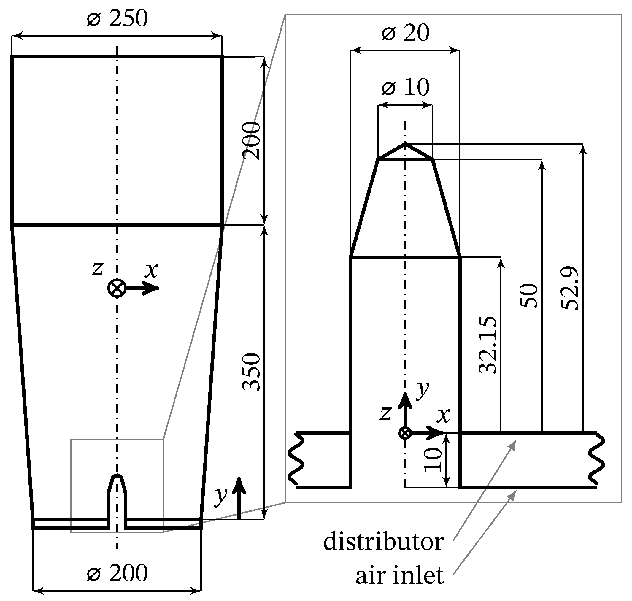
Details of the experimental procedure can be found in the work of Orth et al. [18]. Granulation experiments were performed in the Glatt GF3 fluidized bed granulator installed at the Institute of Solids Process Engineering and Particle Technology at the Hamburg University of Technology. It is equipped with a fluidization air heater and a fan that operates in suction mode. Its dimensions are shown in Figure 2.
A solution of 30 wt% sodium benzoate in distilled water was injected into the process chamber using a peristaltic pump connected to a Schlick 970 S3 two-fluid nozzle (opening diameter 1.2   m m ), which was installed in bottom-spray configuration. The atomization air was supplied from the in-house pressure lines and fed through a preheater into the two-fluid nozzle.
At the start of every experiment, 2 k g of base particles (Cellets 500) were poured into the process chamber and heated up to the process conditions before the start of liquid injection. Liquid injection was terminated after 1 k g of solution, equating to 0.3   k g of sodium benzoate, was fed into the system.
The following operating conditions were chosen to vary:
  • Fluidization air flow rate,
  • fluidization air temperature,
  • liquid spray rate,
  • atomization air pressure and
  • nozzle air temperature.
The full exploration of this parameter space would result in 3 5 = 243 combinations of process parameters, equivalent to 243 × 4   h = 972   h of experimental work under the assumption of 4 h of operating time per experiment. As such, a subset of parameters was chosen and three different values were to be evaluated per parameter, as given in Table 1.
As the focus of this study lies in relating product properties to tracked quantities rather than systematically investigating the physics behind fluidized bed spray granulation, it was chosen to center the experiments around several reference cases, rather than detailing a specific case. The experimental plan, as conducted, is given in Table 2.

2.7. Particle Roughness Quantification

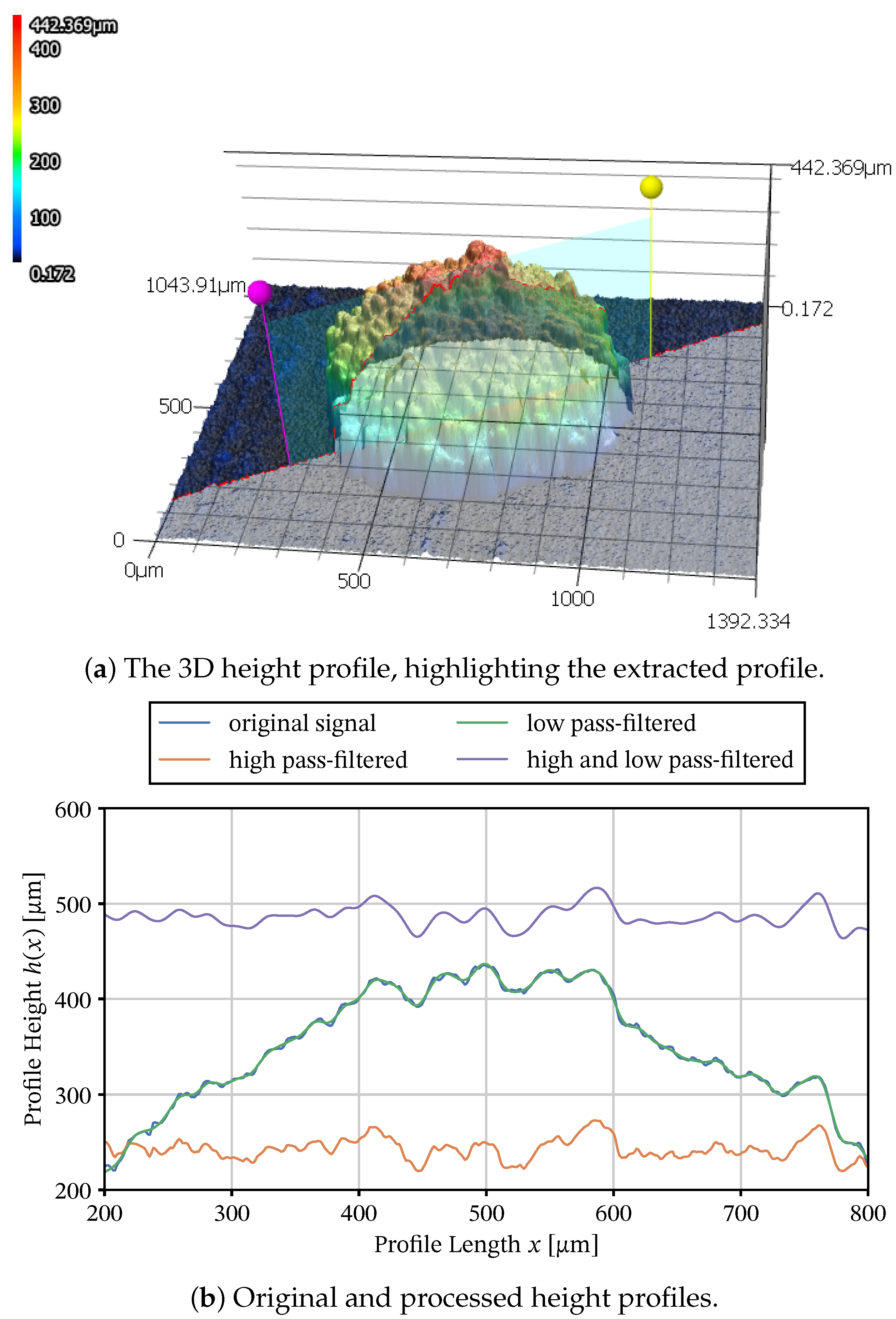
The particles’ roughness is quantified using laser-scanning confocal microscopy, as outlined in the work by Orth et al. [18]. An example particle surface scan is shown in Figure 3a. Corrections for the surface shape were made by filtering the surface profile, as outlined in Figure 3b: A low-pass filter at Δ x min = 8 μm removes the finer features and noise while it retains the overall shape. The remaining particle curvature is removed using a high-pass with a cutoff at Δ x max = 80 μm.

2.8. Pilot-Scale Experiments

To investigate the ability of the devised method to meaningfully describe the influence of changes in mixing due to scale-up, a scale-up of the base case that was used for the development of the tracked quantity-mapping was replicated on a pilot scale in the Glatt GF25 plant. The target quantity is the same as that used for deriving a mapping, the arithmetic mean surface roughness S a .
The pilot-scale granulator at hand has four nozzles. By varying the numbers of nozzles in use, the effect of inhomogeneous liquid injection can be emulated. For example, by channeling all of the liquid through a single nozzle, the influence of mixing on the wetting–drying equilibrium can be selectively studied.
The key differences between the pilot- and lab-scale plants are summarized in Table 3.
We chose to keep
  • the gas velocity,
  • the net spray rate per distributor area and
  • the bed mass per distributor area
constant between lab-scale and pilot-scale in order to ensure stability of operation. The ratio of distributor areas is 0.25   m 2 / 0.0314   m 2 8 . Thus, the fluidization air flow rate V ˙ air , in and net spray rates M ˙ spray are scaled linearly with this factor. This way, the drying potential of the air is conserved globally.
The process conditions were chosen to parallel cases 4–6 and 19 of the laboratory-scale experiments (Table 2). The net spray rate was set at M ˙ spray = 8 × 15   g min 1 or M ˙ spray = 8 × 20   g min 1 , correspondingly. The nozzle configurations that used all four nozzles, the two outermost nozzles and only one nozzle on one end of the fluidized bed were tested in simulations. As the GF25 plant uses larger nozzles, the cap settings were tweaked until the mean droplet size matched that of the nozzle in the GF3 plant, as measured using laser scattering. Despite this, deviations can be expected due to different spray characteristics.

2.9. Simulation Setup

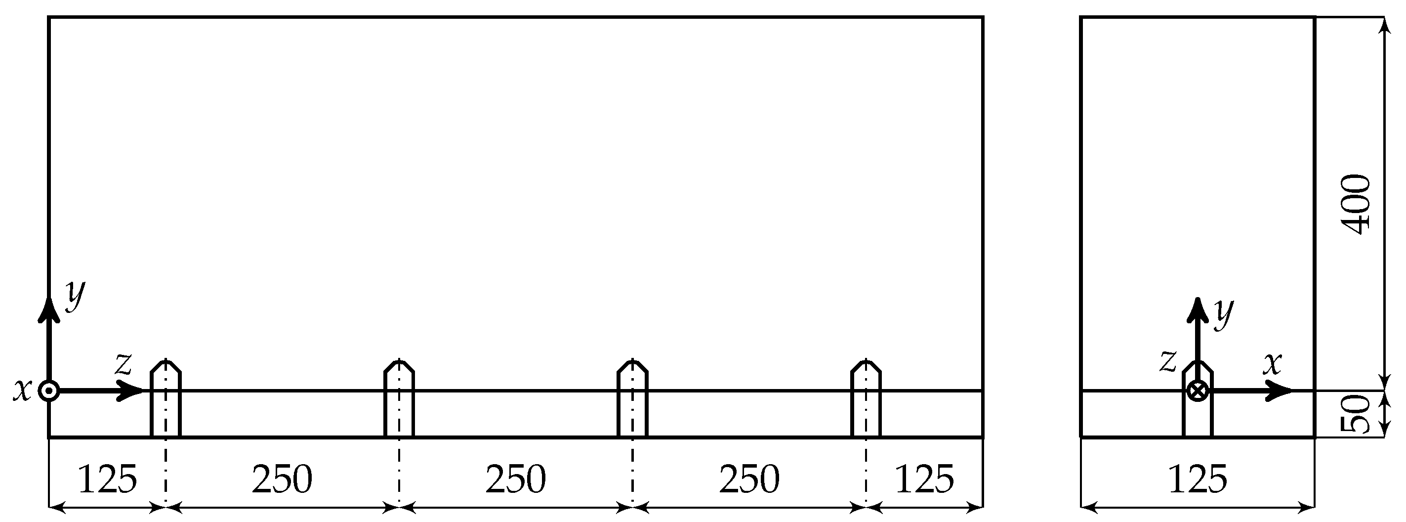
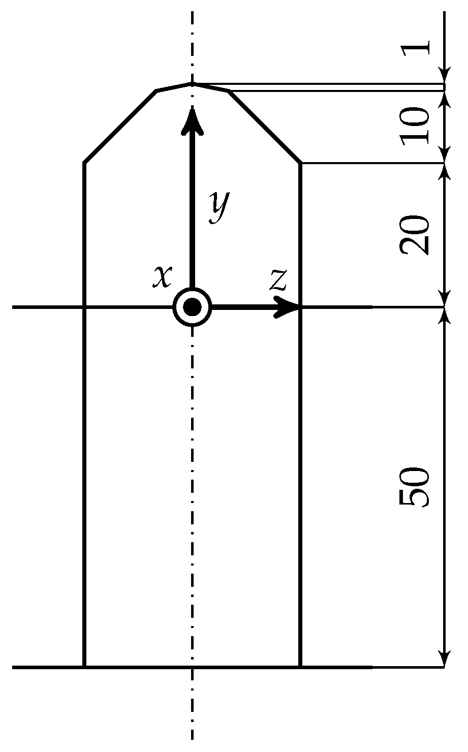
The geometric dimensions of the pilot-scale plant are shown in Figure 4, and the adapted nozzle geometry in Figure 5.
The gas phase was assumed to be an ideal gas that consists of nitrogen gas and water vapor, with the heat capacity calculated using a mixing approach from the fourth-order temperature-dependent polynomials and the viscosity calculated using the Sutherland [19] equation. Droplets are injected above the nozzle patch in order to reproduce the shape of the spray cone. For details on this, please refer to the work of Pietsch et al. [20].
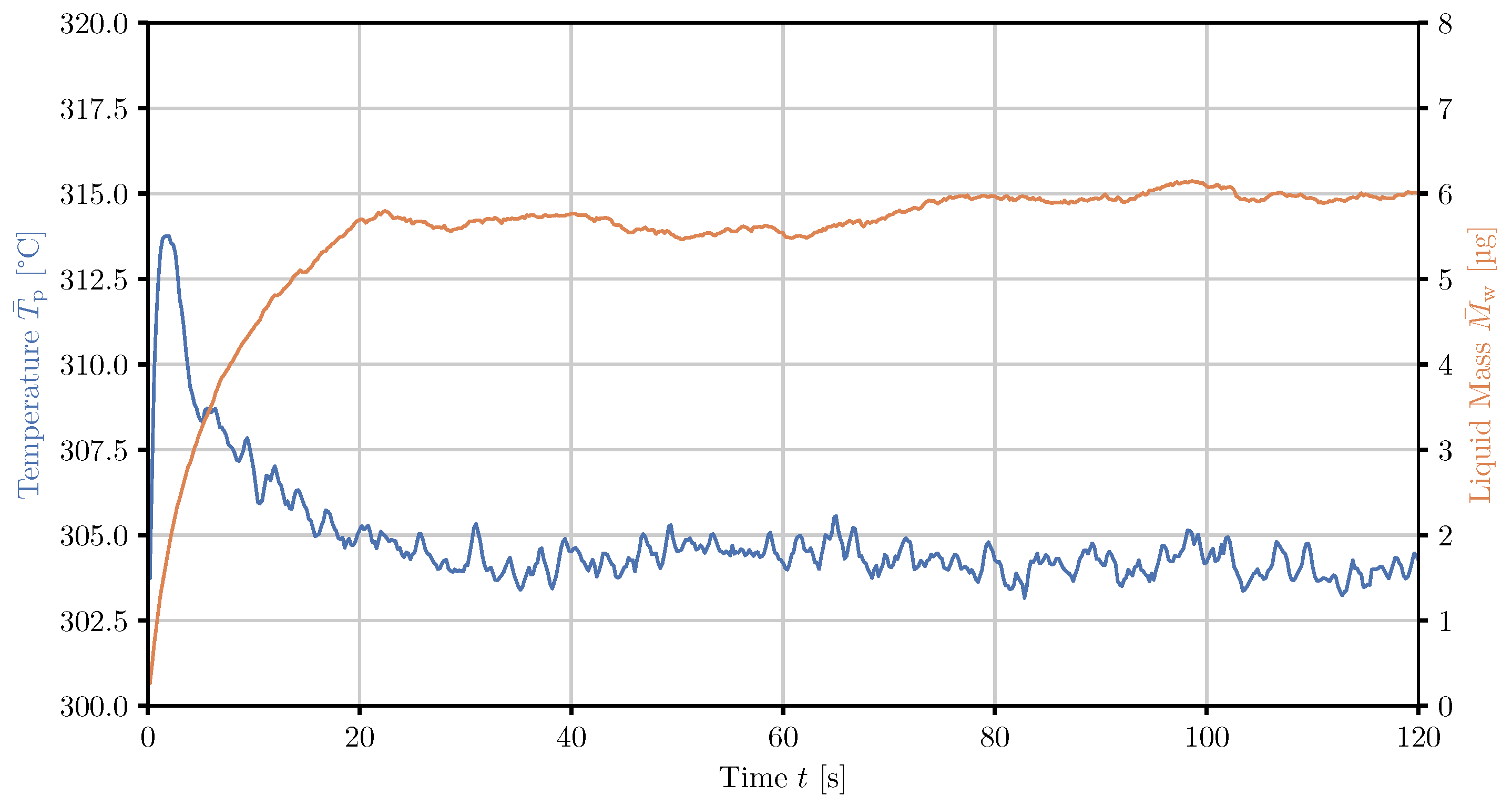
Simulations were run for 20 s without sampling to establish an equilibrium with respect to both temperatures and moisture content and continued for another 10 s for sampling the tracked quantities. This duration was chosen to be twice the time that was required for both mean temperature and mean liquid loading of particles to reach stable values, as shown in Section 3.1.
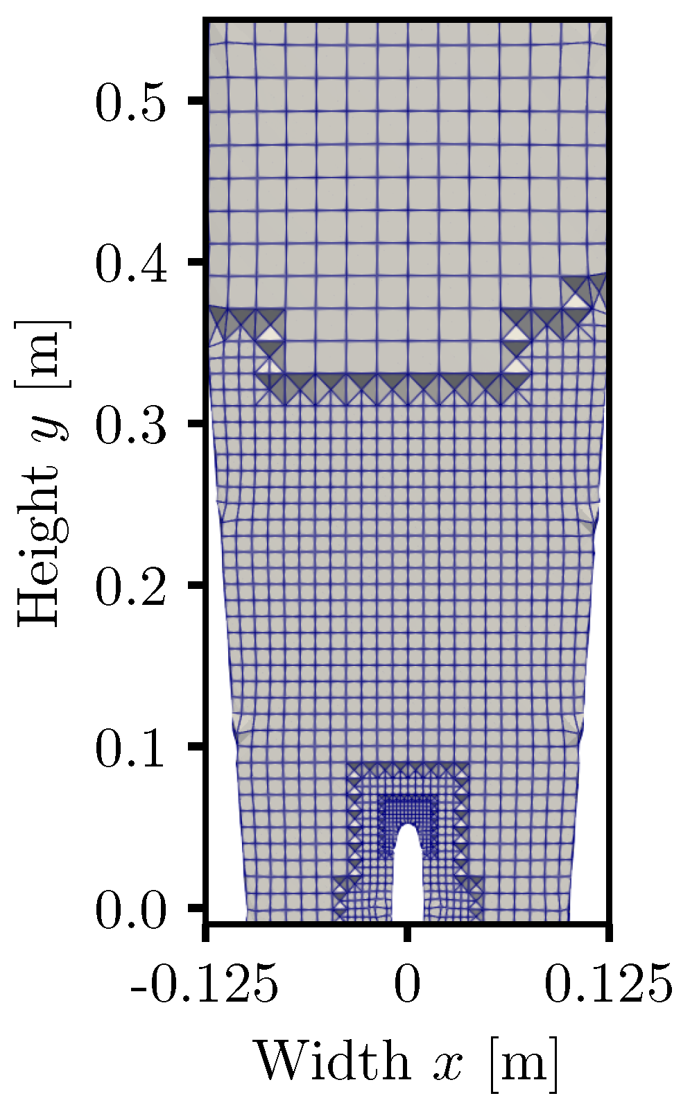
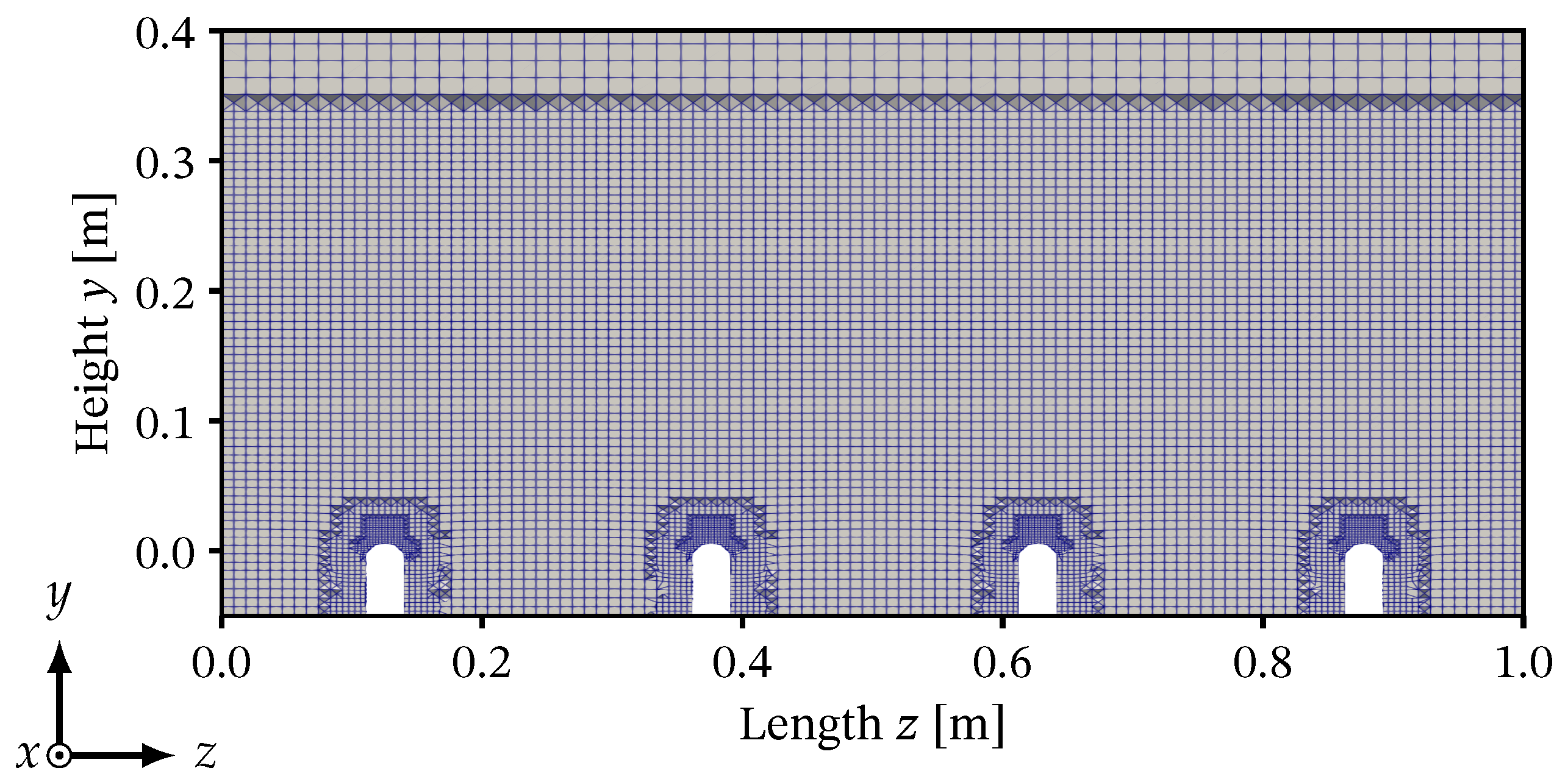
Meshes were created using snappyHexMesh with a grid size of three times the parcel diameter d p , parcel = δ CG d p = 2.6   m m and can be seen in Figure 6 for the lab-scale case and in Figure 7 for the pilot-scale case.
At y = 0   m , a plate was introduced on the DEM side to replicate the effect of a mesh grid that was used in the experiments. The numerical parameters and material properties are given in Table 4. The frictional parameters were chosen in analogy to Kieckhefen et al. [21]. A coarse-graining factor of δ CG = 4 was used to increase the time step to a manageable degree and reduce the number of particles to consider in order to be able to use the same particle properties in simulations of the lab-scale and pilot-scale plants. With this scaling factor, lab-scale apparatus simulations consider 155,233 parcels whereas the pilot-scale apparatus simulations consider 1,241,864 parcels.
The air flow rates and median droplet sizes corresponding to each of the used atomization pressures were determined and can be found in Table 5.

3. Results and Discussion

3.1. Laboratory-Scale Simulations

For deriving a micro-scale mapping with the surface roughness, the surface liquid evaporation time t evap , concentration in droplets upon impact x s , imp as well as the velocity at which droplets impact the particles’ surface v imp are chosen as the tracked quantities.
The simulation with the highest liquid injection rate and lowest air temperature and flow rate, case 3, was used to estimate the equilibration times required. In this case, liquid accumulation is very slow. This in turn influences the extent to which the mean particle temperature reaches an equilibrium, owing to the spatial unevenness of drying and heating zones and transfer of particles between them by mixing. The mean particle temperature and the mean particle surface liquid over time from case 3 are given in Figure 8. Here, it can be identified that the mean liquid mass M ¯ w reaches a steady value after 20 s and the particle temperature after 30 s . For additional safety, the simulation length was set to 60 s overall, allowing for the systems to spend 60 s equilibrating. Since recording these quantities creates a large amount of data, only the last 10 s of the simulation are saved for the surface liquid evaporation time and the last 2.5   s for the other two quantities.
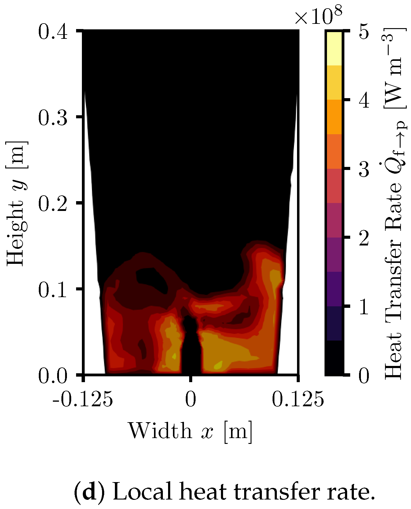
The order of the liquid holdup equilibrating before the mean particle temperature illustrates the aforementioned interplay of wetting, drying and mixing. This is also apparent when observing instantaneous snapshots of the gas temperature, vapor fraction and heat transfer rates in conjunction with particle positions, temperatures and droplet positions in one such case, shown in Figure 9. When focusing in on an area close to the nozzle ( x = 0   m , y = 0.05   m ), a region with very few particles due to the high gas velocities can be identified.
The gas velocity in the proximity of the particles leads to evaporation of liquid in the droplets, observable by the high vapor mass fraction and low temperatures there. Above this vacuole, particles directly exposed to the stream of droplets can be observed ( y = 0.15   m ) where gas and particle temperatures are equilibrated and no substantial heat transfer can be seen. This is due to the high water vapor content in this region.
This pattern repeats at the apparatus walls ( x = 0.1   m , y = 0.05   m ), where wetted particles move downwards after leaving the proximity of the nozzle due to the circulation pattern inherent in fluidized beds. The highest heat transfer rates occur close to the nozzle shaft where particles rise up towards the wetting zone. Here, peak local heat transfer rates of up to 400 k W m 3 can occur due to unconsumed/uncooled gas preferably rising with bubbles towards the center of the granulator, allowing for large temperature gradients. Due to bypass in the form of bubbles and equilibrated zones, the net heat transfer rate will be much lower.
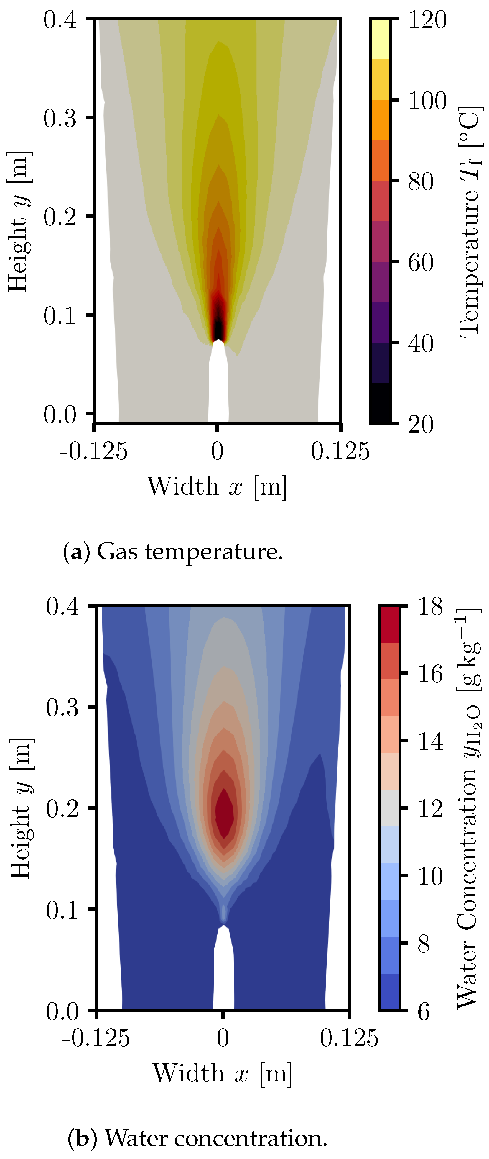
When looking at a very dry case and time-average over 10 s , we can observe that the gas temperature (Figure 10a) does not decrease in large regions of the bed, indicating that drying occurs directly after spray deposition or in the form of overspray. This is confirmed when observing the time-averaged gas phase moisture distribution (Figure 10b), where the highest vapor fractions occur about 10 c m above the nozzle.
Furthermore, averaging over 10 s of time, the duration during which the tracked quantities were sampled, revealed largely symmetric temperature and moisture fields, indicating that the simulation has converged with respect to mixing patterns, as well as heat and mass transfer.

3.2. Pilot-Scale Simulations

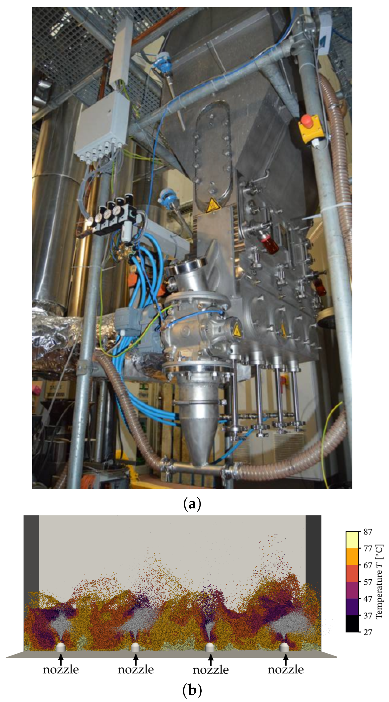
The simulations of the pilot-scale plant (Figure 11a) showed the bubbling behavior that is characteristic for fluidized beds of Geldart type B particles (Figure 11b).
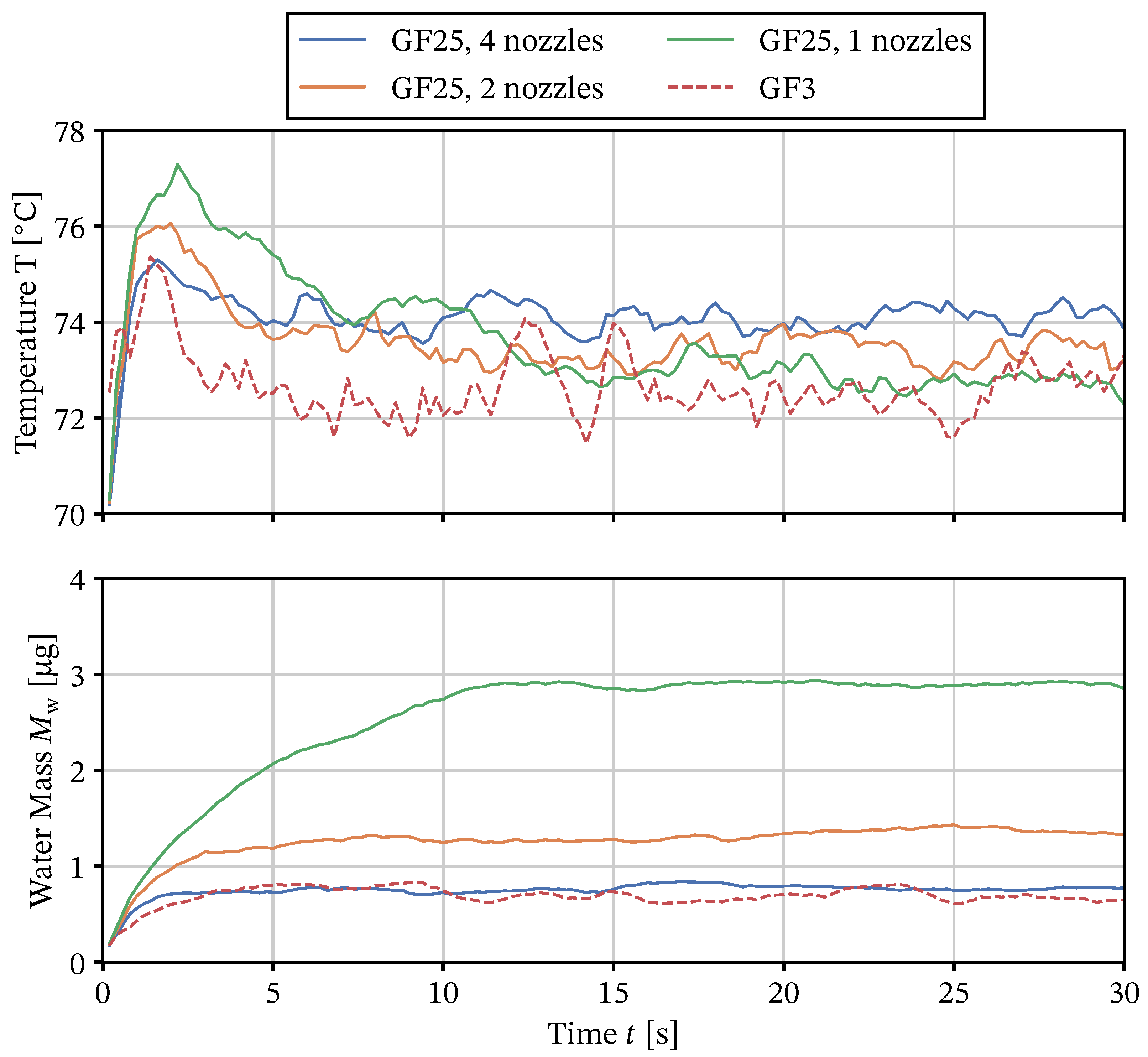
The simulations achieved a stable mean particle temperature after about 8 s for the pilot-scale cases with two and four nozzles, as well as the lab-scale case, while the single nozzle required about 15 s , as shown in Figure 12. All of the simulations approached a long-time mean temperature of 74 C . A shortcut approximation of the temperature decrease in the system due to evaporation (and neglecting the change in heat capacity of the gaseous phase) gives a temperature change of
Δ T = M ˙ spray ( 1 x s , 0 ) Δ h LV V ˙ air , in ρ air c p , air
= ( 120   g min 1 ) ( 1 0.3 ) ( 2500   kJ  k g 1 ) ( 840   m 3   h 1 ) ( 1.2   k g   m 3 ) ( 1.01   kJ  k g 1 K 1 )
= 11 K .
Given the inflowing air temperature of 85 C , this is in line with the resulting particle temperatures, confirming that most of the evaporation takes place on the particles’ surface rather than by spray in the gas phase. The corresponding per-particle surface liquid contents (Figure 12), however, differ drastically between cases. While the case with four nozzles and the lab-scale GF3 case show almost the same temporal behavior, reaching an equilibrium surface liquid content of 1.3   μ g within less than 5 s , the equilibrium surface liquid content of the system with two nozzles was at 2.5   μ g and that with one nozzle at 6 μ g . Given that these figures average over the entire system, only the rate at which they approach equilibrium values shows an influence of the position of liquid injection. Furthermore, averaging over the entire apparatus glosses over the complexities of mixing within that are taking place.
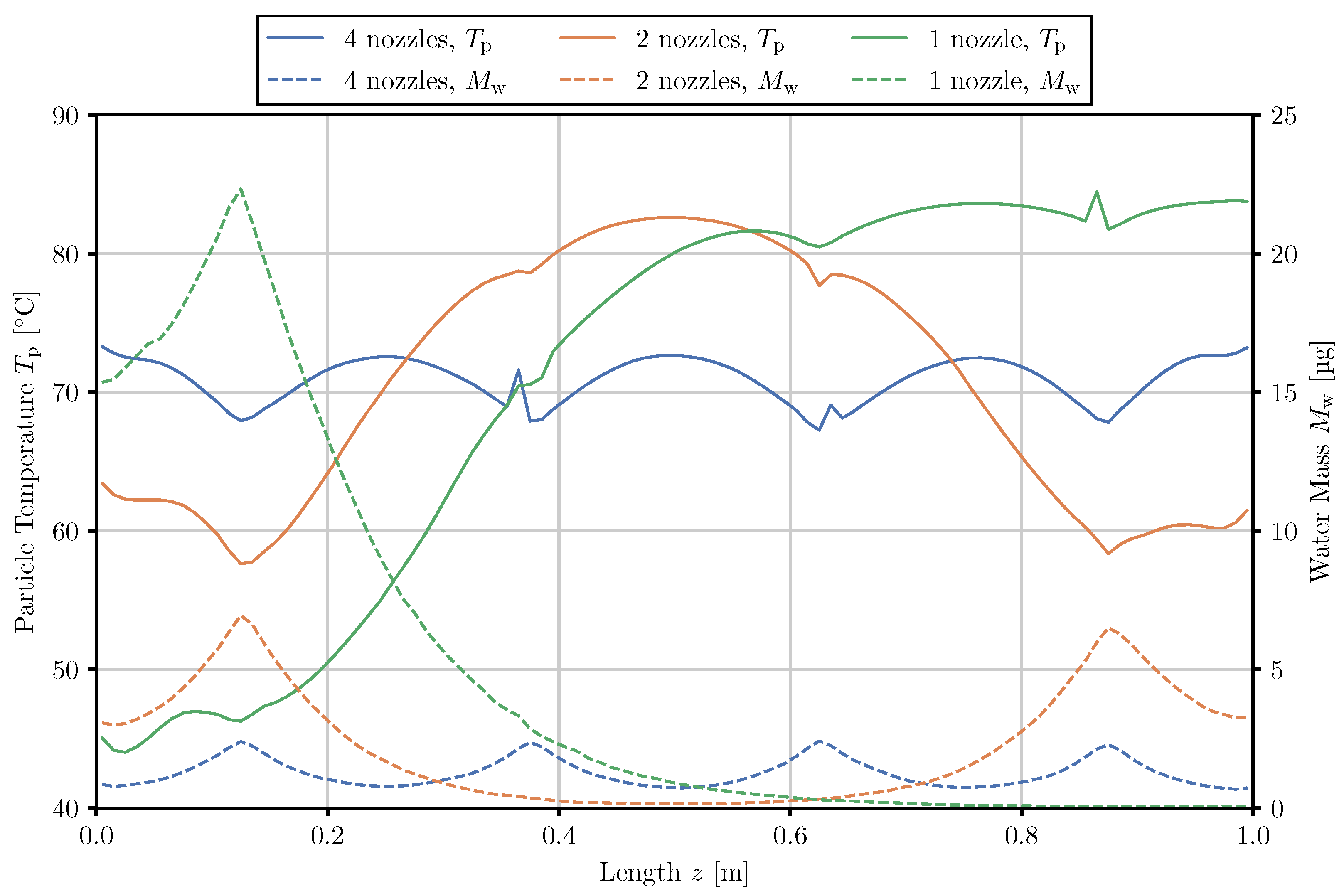
Looking at the time-averaged spatial distribution of particle surface liquid and temperature along the apparatus length (Figure 13), the reason for the disparity becomes apparent: The particle temperatures are the lowest where liquid is injected and the mean surface liquid is the highest. For the case with four and two active nozzles, an entirely symmetric profile of temperature of particle surface liquid mass can be observed. Meanwhile, for four nozzles, the liquid mass peaks around 2.5   μ g at the nozzles and falls to less than 1 μ g between the nozzles, and the two nozzle-scenario peaks at above 6 μ g and falls to almost 0 μ g for the innermost 0.4   m of the apparatus. With one nozzle in operation, the particle liquid mass reaches 23 μ g at the location of injection and falls to almost zero at a distance of 0.5   m .
On the thermal side of the matter, the opposite picture emerges. Wherever liquid is injected or transported to, the temperature drops due to evaporation. As the nozzle air is colder than the fluidization air, this introduces dips at nozzle locations that are operated without liquid injection. Gas bypass at the walls, and thus locally increased particle heating, is visible in every case. With four nozzles in operation, the temperature is relatively homogeneous within a 10 C corridor around 70 C , indicating a very consistent distribution of heating of particles that have been cooled due to evaporation. In contrast, with one nozzle, particles that are about 0.4   m away from liquid injection already reach a temperature of 80 C and the same applies to two nozzles and a distance of 0.25   m .
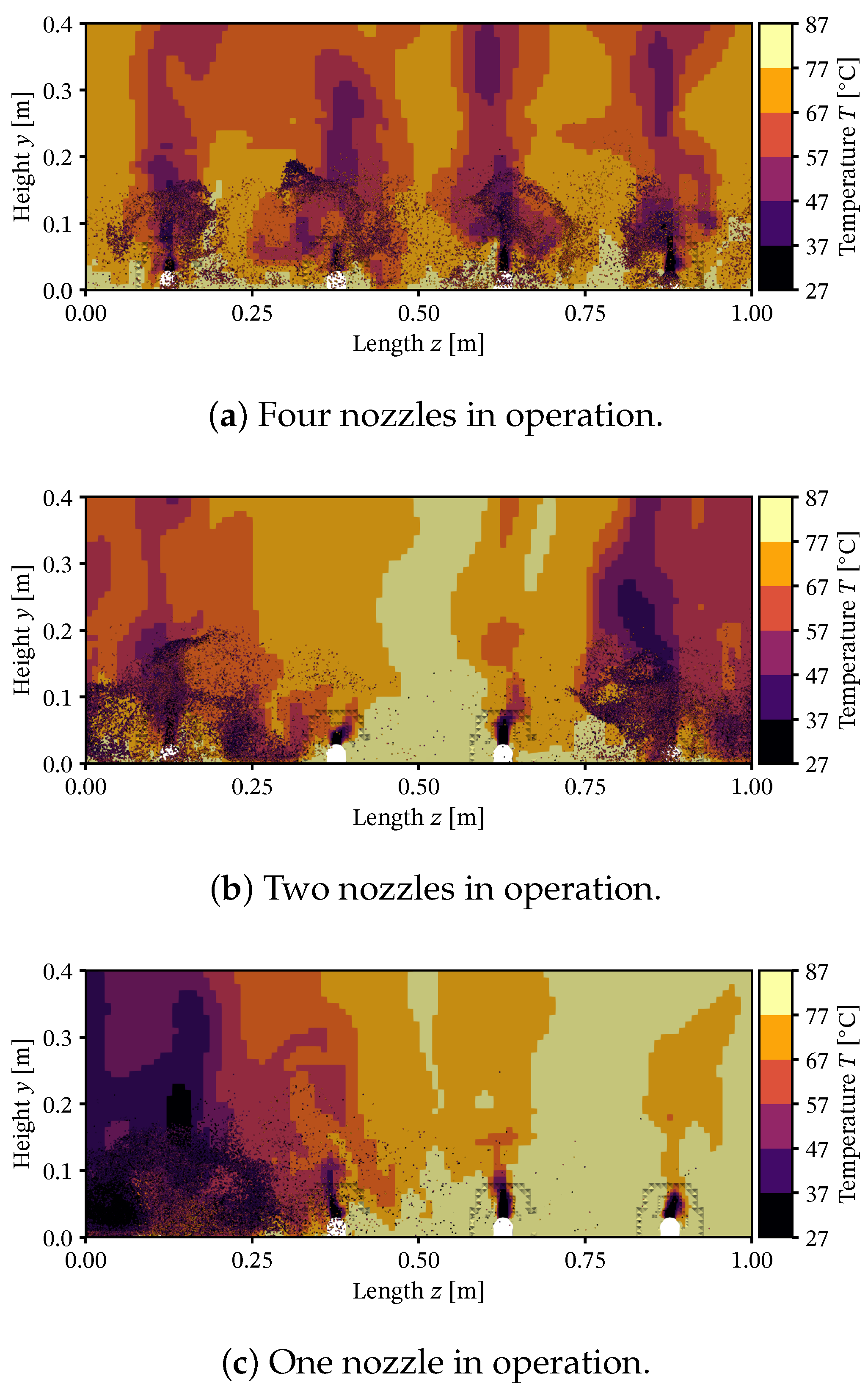
The corresponding, but instantaneous, gas temperature fields are shown in Figure 14. For four nozzles, clear heating and drying zones can be identified. In the first 0.025   m of the apparatus height, the gas temperature is reduced from the initial 85 C by 10 C or more, indicating that particles are being heated and/or dried. When one or two nozzles are in operation, regions of the apparatus can be identified, where gas just passes the particle bed with no significant heat exchange.
Due to the data being a cut through the mid-plane where the nozzles operate, very localized spots of cold air are visible that reduce the temperature locally by about 10 C . All of this shows that for excessive nozzle distances, most of the apparatus operates without contributing to the process at all.
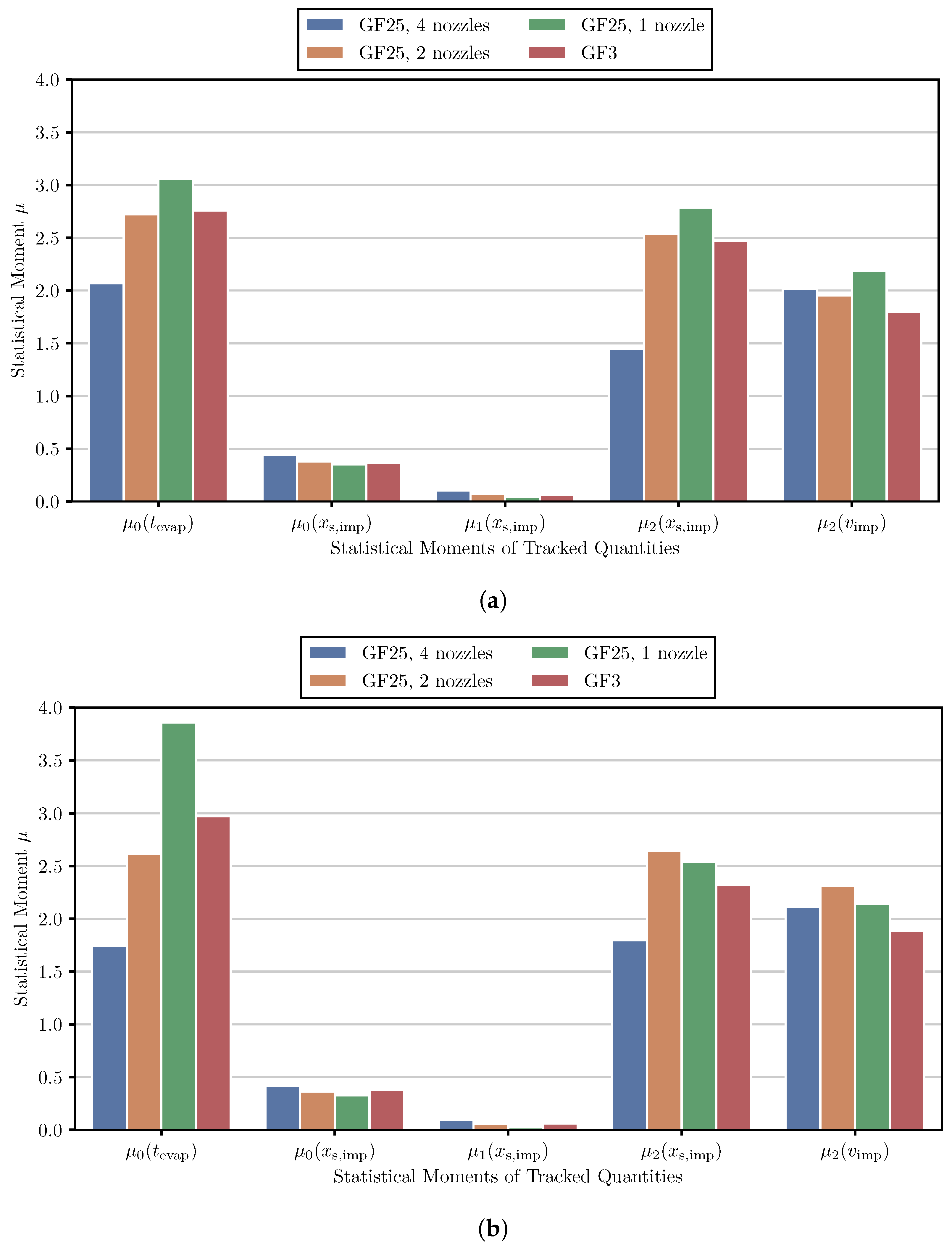
Looking at tracked quantities that result from the process (Figure 15), consequences for the micro-processes on the particle surface can be suggested. The particle liquid layer evaporation time distribution shows that for all cases present, the majority of particles dry in less than 1 s . This can be attributed to the majority of particles that are wetted only by a few droplets: The chance for particles to receive a few droplets further away from the spray zone is much higher than to be in the spray zone and receive a lot of liquids. As the amount of liquid received correlates with the time it takes to evaporate under equivalent conditions, the evaporation time increases correspondingly.
The corresponding mean liquid layer evaporation time, shown in Figure 15a as μ 0 ( t evap ) , is the highest for one nozzle, followed by two and four nozzles, respectively. Notably, the mean evaporation time on the lab scale (GF3) that corresponds closest to the pilot scale is the one with two nozzles. This is also true for a higher spray rate of 8 × 20   g   min 1 , where this trend is much more pronounced: The mean evaporation time with four nozzles lies at 1.8   s whereas the one for two nozzles is at 3.6   s and one single nozzle at 4.9   s . The reason for this behavior lies in the distance that wetted particles have to be transported before drying is completed (as previously mentioned when discussing Figure 13 and Figure 14), as well as the larger amount of liquid per particle that has to be removed (see Figure 12).
The solids concentration in the droplets upon impact, shown in the same figure, follows a Weibull distribution with a long tail end for all cases. The shape of this distribution can be explained with a time-average: Some droplets are transported further than others and, therefore, have a longer time to dry before encountering a particle.
For the pilot-scale case (GF25) with one nozzle, the peak of the distribution is at a value of x s , imp = 0.31 , and at x s , imp = 0.33 for two nozzles. The four-nozzle pilot-scale case has its maximum at x s , imp = 0.36 . This behavior can be explained with the low rates of drying due to higher humidity of the air.
The degree to which droplets that have a longer lifetime can dry is much more compressed with fewer nozzles, as more liquid is introduced in a smaller area, leading to higher humidity. Interestingly, the solids concentration distribution of the lab-scale apparatus is much more similar to the one obtained at the pilot scale with one or two nozzle than four nozzles, as is the case with the liquid layer evaporation time distribution.
When considering the statistical moments of the tracked quantities that were identified as the most important in the product property mapping, given in Figure 15a,b, the pilot-scale configuration with two nozzles most closely matched that of the lab-scale trial for a spray rate of M ˙ spray = ( 8 × ) 15   g   min 1 with very little deviation. For a higher spray rate of M ˙ spray = ( 8 × ) 20   g   min 1 , this is not the case for the second statistical moment of the impact solids concentration μ 2 ( x s , imp ) and the impact velocity μ 2 ( v imp ) where the one-nozzle variant is more similar.

3.3. Product-Property Tracked Quantity Mapping

The tracked quantities, namely the surface liquid evaporation time t evap , the solids concentration in droplets upon impact x s , imp and the impact velocity of droplets on the particle surface v imp are the consequence of the global process conditions and the geometry of the apparatus.
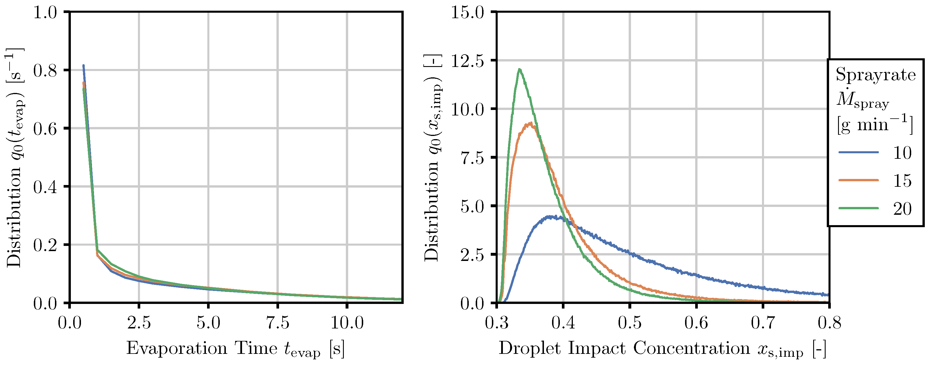
All other parameters being equal, variation in the spray rate (Figure 16) does not substantially increase the droplet impact solids concentration distribution. The solids concentration in impacting droplets is determined by droplet drying, which is limited by the saturation of the atomization air. The scenario with a relatively low spray rate ( M ˙ spray = 10   g   min 1 ) thus shows the droplet impact concentration curve shifted to much higher values compared to the other cases ( M ˙ spray > 10   g   min 1 ). In contrast to this, the effect of increasing the spray rate to a degree in which drying takes place all over the granulator would impact surface liquid evaporation times, while the droplet impact concentration remains the same. This scenario is very much a hypothetical as, for this temperature, spray rates higher than 20   g   min 1 would suffer from substantial agglomeration.
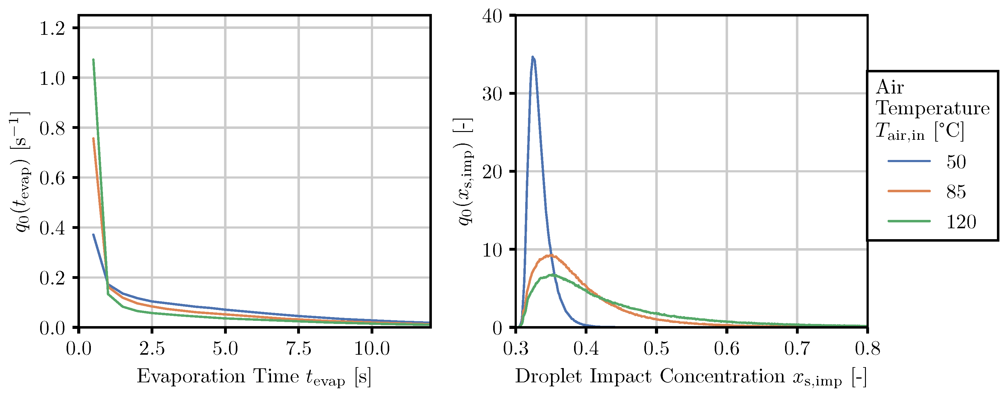
This exact effect can be seen when considering a variation in fluidization air temperatures (Figure 17). A low air temperature leads to a shift towards longer surface liquid evaporation times and lower solids concentration on particle impact due to lower drying rates and faster saturation of air in the granulator. The droplet impact concentration curves for T air , in = 50   C reveal almost no droplet drying at this temperature, and the two higher temperatures have much wider distributions, albeit with a similar maximum value.
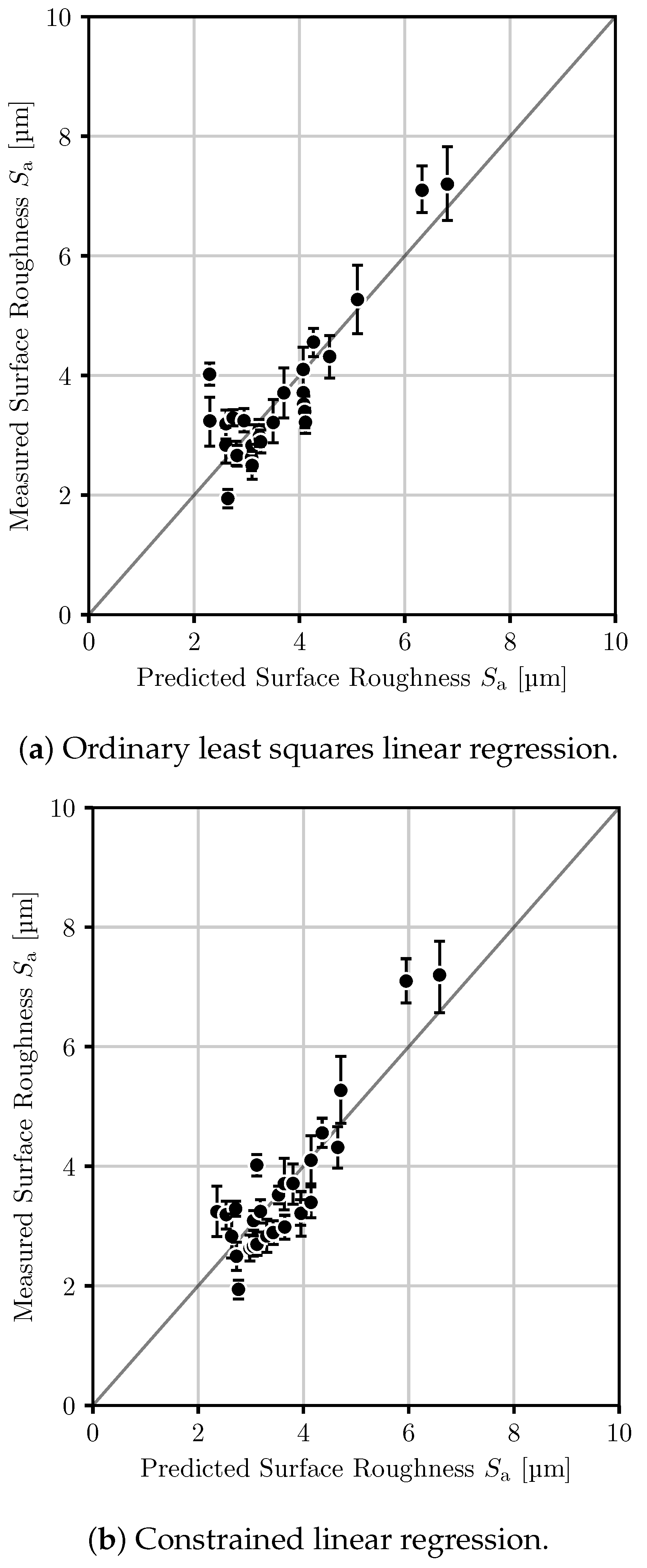
A mapping between tracked quantities and particle properties, chosen to be the arithmetic mean surface roughness S a , was found using the ordinary least squares method as well as L 1 -regularized linear regression. As before with the ordinary least squares method, statistically insignificant parameters were eliminated to yield
S a = μ 0 ( t evap ) μ 0 ( x s , imp ) μ 1 ( x s , imp ) μ 2 ( x s , imp ) μ 2 ( v imp ) · 0.795 15.0 45.8 1.31 3.25 , ,
where units were omitted for brevity and the parity plot can be seen in Figure 18a. Notably, the constant contribution was eliminated entirely (with p > 0.15 for this hypothesis), as well as four other tracked quantities to yield a five-parameter expression. To judge the quality of this fit, using the full residual
R 2 = 1 N i y i measured y i predicted 2
is not sufficient, as for every experiment, multiple roughness measurements are present. Therefore, the median roughness y i 50 , measured was used. Thus, the best possible reproduction in a fit would still produce a residual of
R min 2 = 1 N i y i 50 , measured y i predicted 2 = 1.32   μm 2 ,
which has to be taken into account. For the given five-parameter expression, a residual of 1.59   μm 2 results. In contrast, using a 7-parameter expression that results from both L 1 -regularized regression and assuming the relevance of a constant parameter and eliminating other terms gives the same expression:
S a = 7.91 + μ 0 ( t evap ) μ 1 ( t evap ) μ 1 ( x s , imp ) μ 2 ( x s , imp ) μ 1 ( v imp ) μ 2 ( v imp ) · 0.959 0.493 29.3 1.62 3.44 2.83 .
This carries a residual of 1.53   μm 2 and its parity plot is shown in Figure 18b. Given the bias of the parameter selection in L 1 -regularized regression to include the intercept in the fit on account of there being no penalty term for this, the equivalence of these is not surprising. On the basis of very similar residuals, the five-parameter expression Equation (32) is preferable.

3.4. Prediction of Product Properties on the Pilot-Scale

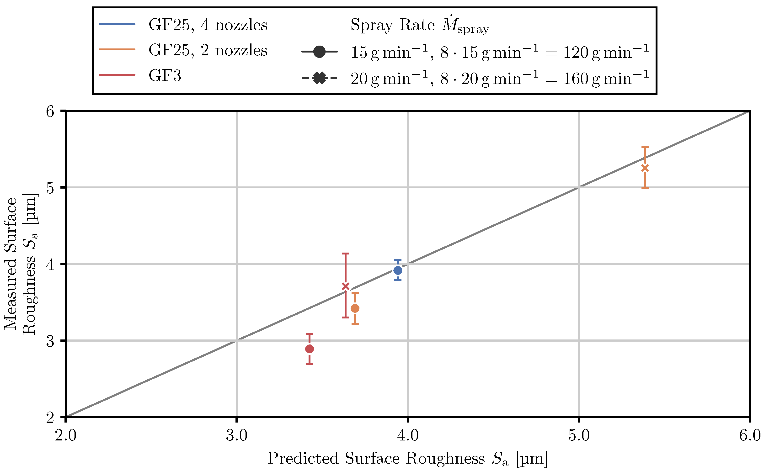
When applying the five-parameter mapping between the arithmetic mean surface roughness S a and tracked quantities (Equation (32)), an excellent agreement can be observed in the parity plot (Figure 19).
The case with the lower spray rate, M ˙ spray = ( 8 ) × 15   g   min 1 , shows a deviation of less than 1 μm with respect to experimentally observed values, with the GF25 with two nozzles producing similar products to the GF3 plant. The GF25 plant with four nozzles, on the other hand, produces rougher particles. Looking at the predictions, the absolute values are within an accuracy window smaller than 1 μm. The correct order of roughnesses for the different plant configurations considered can also be described. This degree of accuracy is to be expected given that the shapes of distributions of the tracked quantity match.
For a spray rate of M ˙ spray = ( 8 ) × 20   g   min 1 , the results are correct. Impressively, the production of particles with much higher roughness (by 2   μm ) for the GF25 plant with two nozzles versus the corresponding GF3 experiment is predicted by the approach. This demonstrates that the approach can accurately depict the deviations in local wetting and drying conditions that arise when scaling to another plant and consider the consequence of these deviations.
All of these results are in line with the observation that wetter drying conditions and lower temperatures produced particles with rougher surfaces in the lab-scale experiment of Orth et al [18].

4. Conclusions

The final properties of the product of a fluidized bed layering granulation process depend on the microprocesses that occur on the surface of the particles or inside of the droplets that impact the particles’ surface. An indirect particle-property prediction approach using tracked per-particle quantities instead of directly resolved micro-scale processes was developed. The approach was able to derive meaningful mappings between the properties of the final product and the so-called tracked quantities in lab-scale granulation experiments that used salt solutions as spray liquid.
The experiments of Orth et al. [18], that form the foundation of this study, were conducted by injecting a sodium benzoate solution onto Geldart group B micro-crystalline cellulose particles (Cellets). A set of five statistical moments of the tracked quantities, namely the liquid layer evaporation time, the solids concentration in droplets upon impact and droplet impact velocity, mapped the local process conditions that droplets experience to the resulting surface roughness.
The predictiveness of the approach in scale-up was shown in scaling the lab-scale process from the laboratory scale to the pilot scale, by a factor of eight, keeping bed height in the system, temperature, net spray rate per distributor area and, thus, gas velocity, constant. The number of nozzles in the pilot-scale experiments was varied between one and four while keeping the net liquid spray rate constant. This challenges the accurate representation of wetting, mixing and evaporation. The surface roughness was predicted to be higher than in the laboratory-scale trials when keeping thermal and net spray conditions constant, no matter how many nozzles were in use. Due to the worse mixing in the pilot-scale plant, localized drying conditions close to the nozzles are much wetter. These deviations were reflected in the tracked quantities and the derived mapping was able to quantitatively predict the surface roughness.

Author Contributions

Conceptualization, P.K., S.P.-B. and S.H.; Data curation, P.K.; Formal analysis, P.K.; Funding acquisition, S.P.-B. and S.H.; Investigation, P.K.; Methodology, P.K.; Project administration, S.P.-B.; Resources, P.K., S.P.-B. and S.H.; Software, P.K.; Supervision, S.P.-B. and S.H.; Validation, P.K.; Visualization, P.K.; Writing—original draft, P.K.; Writing—review and editing, P.K., S.P.-B. and S.H. All authors have read and agreed to the published version of the manuscript.

Funding

Paul Kieckhefen acknowledges funding from BASF SE.

Institutional Review Board Statement

Not applicable.

Informed Consent Statement

Not applicable.

Data Availability Statement

Not applicable.

Acknowledgments

Parts of this work are reprinted from [7] with permission from Cuvilier Verlag, Göttingen. The authors thank ingrediantpharm for providing the Cellets particles for the experiments.

Conflicts of Interest

The authors declare no conflict of interest.

References

  1. Hoffmann, T.; Rieck, C.; Bück, A.; Peglow, M.; Tsotsas, E. Influence of Granule Porosity during Fluidized Bed Spray Granulation. Procedia Eng. 2015, 102, 458–467. [Google Scholar] [CrossRef] [Green Version]
  2. Rieck, C.; Hoffmann, T.; Bück, A.; Peglow, M.; Tsotsas, E. Influence of Drying Conditions on Layer Porosity in Fluidized Bed Spray Granulation. Powder Technol. 2015, 272, 120–131. [Google Scholar] [CrossRef]
  3. Schmidt, M.; Bück, A.; Tsotsas, E. Experimental Investigation of the Influence of Drying Conditions on Process Stability of Continuous Spray Fluidized Bed Layering Granulation with External Product Separation. Powder Technol. 2017, 320, 474–482. [Google Scholar] [CrossRef]
  4. Diez, E.; Meyer, K.; Bück, A.; Tsotsas, E.; Heinrich, S. Influence of Process Conditions on the Product Properties in a Continuous Fluidized Bed Spray Granulation Process. Chem. Eng. Res. Des. 2018, 139, 104–115. [Google Scholar] [CrossRef]
  5. Batista, J.; Santos, D.; Béttega, R. Determination of the Physical and Interaction Properties of Sorghum Grains: Application to Computational Fluid Dynamics–Discrete Element Method Simulations of the Fluid Dynamics of a Conical Spouted Bed. Particuology 2021, 54, 91–101. [Google Scholar] [CrossRef]
  6. Bahramian, A.; Olazar, M. Evaluation of Elastic and Inelastic Contact Forces in the Flow Regimes of Titania Nanoparticle Agglomerates in a Bench-Scale Conical Fluidized Bed: A Comparative Study of CFD-DEM Simulation and Experimental Data. Chem. Eng. Res. Des. 2021, 176, 34–48. [Google Scholar] [CrossRef]
  7. Kieckhefen, P. A Novel Method for Predicting Product Properties in Fluidized Bed Spray Granulation; Number 19 in SPE-Schriftenreihe; Cuvillier Verlag: Göttingen, Germany, 2021. [Google Scholar]
  8. Golshan, S.; Sotudeh-Gharebagh, R.; Zarghami, R.; Mostoufi, N.; Blais, B.; Kuipers, J. Review and Implementation of CFD-DEM Applied to Chemical Process Systems. Chem. Eng. Sci. 2020, 221, 115646. [Google Scholar] [CrossRef]
  9. Kieckhefen, P.; Pietsch, S.; Dosta, M.; Heinrich, S. Possibilities and Limits of Computational Fluid Dynamics–Discrete Element Method Simulations in Process Engineering: A Review of Recent Advancements and Future Trends. Annu. Rev. Chem. Biomol. Eng. 2020, 11, 397–422. [Google Scholar] [CrossRef] [PubMed] [Green Version]
  10. Goniva, C.; Kloss, C.; Deen, N.G.; Kuipers, J.A.; Pirker, S. Influence of Rolling Friction on Single Spout Fluidized Bed Simulation. Particuology 2012, 10, 582–591. [Google Scholar] [CrossRef]
  11. Kinaci, M.E.; Lichtenegger, T.; Schneiderbauer, S. A CFD-DEM Model for the Simulation of Direct Reduction of Iron-Ore in Fluidized Beds. Chem. Eng. Sci. 2020, 227. [Google Scholar] [CrossRef]
  12. Kieckhefen, P.; Lichtenegger, T.; Pietsch, S.; Pirker, S.; Heinrich, S. Simulation of Spray Coating in a Spouted Bed Using Recurrence CFD. Particuology 2018, 42, 92–103. [Google Scholar] [CrossRef]
  13. Gunn, D. Transfer of Heat or Mass to Particles in Fixed and Fluidised Beds. Int. J. Heat Mass Transf. 1978, 21, 467–476. [Google Scholar] [CrossRef]
  14. Kariuki, W.I.; Freireich, B.; Smith, R.M.; Rhodes, M.; Hapgood, K.P. Distribution Nucleation: Quantifying Liquid Distribution on the Particle Surface Using the Dimensionless Particle Coating Number. Chem. Eng. Sci. 2013, 92, 134–145. [Google Scholar] [CrossRef]
  15. Stull, D.R. Vapor Pressure of Pure Substances. Organic and Inorganic Compounds. Ind. Eng. Chem. 1947, 39, 517–540. [Google Scholar] [CrossRef]
  16. Lichtenegger, T.; Peters, E.; Kuipers, J.; Pirker, S. A Recurrence CFD Study of Heat Transfer in a Fluidized Bed. Chem. Eng. Sci. 2017, 172, 310–322. [Google Scholar] [CrossRef]
  17. Pedregosa, F.; Varoquaux, G.; Gramfort, A.; Michel, V.; Thirion, B.; Grisel, O.; Blondel, M.; Prettenhofer, P.; Weiss, R.; Dubourg, V.; et al. Scikit-Learn: Machine Learning in Python. J. Mach. Learn. Res. 2011, 12, 2825–2830. [Google Scholar]
  18. Orth, M.; Kieckhefen, P.; Pietsch, S.; Heinrich, S. Correlating Granule Surface Structure Morphology and Process Conditions in Fluidized Bed Layering Spray Granulation. KONA Powder Part. J. 2021, 39, 230–239. [Google Scholar] [CrossRef]
  19. Sutherland, W. The Viscosity of Gases and Molecular Force. Lond. Edinb. Dublin Philos. Mag. J. Sci. 1893, 36, 507–531. [Google Scholar] [CrossRef] [Green Version]
  20. Pietsch, S.; Kieckhefen, P.; Müller, M.; Schönherr, M.; Kleine Jäger, F.; Heinrich, S. Novel Production Method of Tracer Particles for Residence Time Measurements in Gas-Solid Processes. Powder Technol. 2018, 338, 1–6. [Google Scholar] [CrossRef]
  21. Kieckhefen, P.; Pietsch, S.; Höfert, M.; Schönherr, M.; Heinrich, S.; Kleine Jäger, F. Influence of Gas Inflow Modelling on CFD-DEM Simulations of Three-Dimensional Prismatic Spouted Beds. Powder Technol. 2018, 329, 167–180. [Google Scholar] [CrossRef]
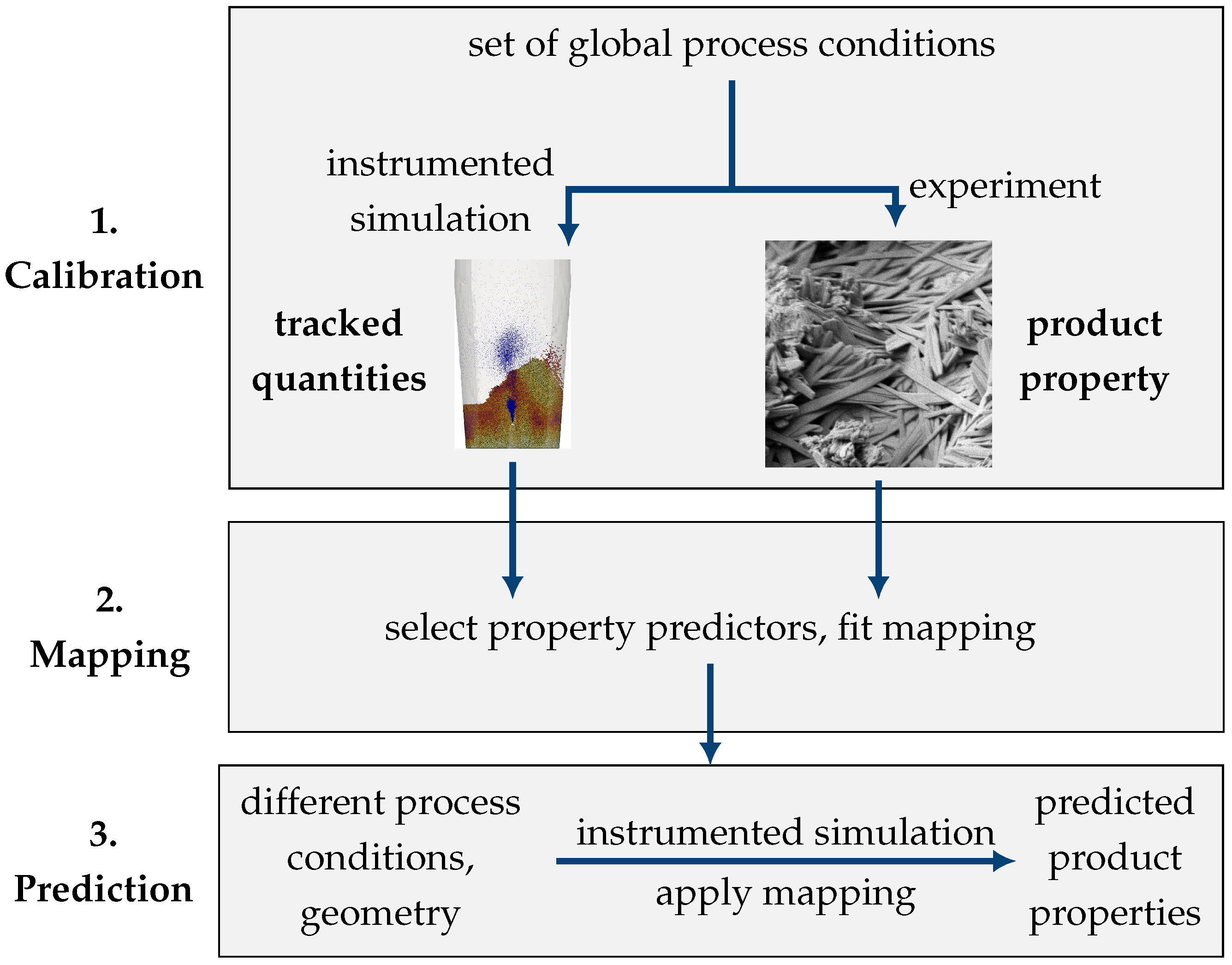
Figure 1. Schematic of the proposed approach to correlate the tracked quantity with product property.
Processes 10 01291 g001
Figure 2. Dimensions of the lab-scale granulator (Glatt GF3) model in m m .
Processes 10 01291 g002
Figure 3. Example result of laser-scanning confocal microscopy: 3D profile (a) and post-processing of extracted line profile for later roughness calculation (b).
Processes 10 01291 g003
Figure 4. Dimensions of the simulation domain of the GF25 pilot-scale plant in m m .
Processes 10 01291 g004
Figure 5. Dimensions of the nozzle of the GF25 pilot-scale plant.
Processes 10 01291 g005
Figure 6. Mesh of for simulations of the GF3 lab-scale plant.
Processes 10 01291 g006
Figure 7. Cross-section of the mesh used for the simulations of the pilot-scale GF25 plant in m m .
Processes 10 01291 g007
Figure 8. Mean particle temperature and mean particle surface liquid over time in case 3 of Orth et al. [18], with a fluidization gas velocity of V ˙ air = 80   N m 3 h 1 and temperature of T air , in = 50   C , a spray rate of M ˙ spray = 20   g  min 1 , an atomization pressure of p spray = 0.5 ¯ and a spray air temperature of 20   C .
Processes 10 01291 g008
Figure 9. Instantaneous simulation snapshots showing gas and particle temperature, spray cloud, water concentration in the gas phase and the rate of heat transfer in the apparatus midplane ( z = 0 ). The process conditions were set for the reference case at a fluidization gas velocity V ˙ air = 105   N  m 3 h 1 and temperature T air , in = 85   C , an atomization pressure of p spray = 1.8 bar and a spray air temperature of 70   C , corresponding to experiments (4)–(6).
Processes 10 01291 g009aProcesses 10 01291 g009b
Figure 10. Time-averages over 10 s of simulation time, showing gas temperature and water concentration in the gas phase in the apparatus midplane ( z = 0 ). The process conditions were set at a fluidization gas velocity V ˙ air = 130   N m 3   h 1 and temperature T air , in = 120   C , a spray rate of M ˙ spray = 10   g min 1 , an atomization pressure of p spray = 3.0 bar and a spray air temperature of 20 °C.
Processes 10 01291 g010
Figure 11. Photo of the GF25 plant and a snapshot of a representative simulation showing the injection of droplets through all four nozzles into the bubbling fluidized bed. (a) Photo of the Glatt GF25 pilot-scale granulator plant. (b) Simulation snapshot of the GF25 simulations, showing the temperatures of the particles, and the positions of the droplets, indicated in white.
Processes 10 01291 g011
Figure 12. Mean particle temperature and per-parcel water mass over time for the GF25 pilot-scale plant in three nozzle configurations and the GF3 lab-scale plant operated at a spray rate M ˙ spray = ( 8 × ) 15   g   min 1 .
Processes 10 01291 g012
Figure 13. Distribution of particle surface liquid/water mass and particle temperature across the apparatus length for the same net amount of liquid ( M ˙ spray = 8 × 15   g   min 1 ) injected through one, two and four nozzles.
Processes 10 01291 g013
Figure 14. Particle and gas phase temperatures in the GF25 plant (spray rate M ˙ spray = 8 × 20   g   min 1 ) after a 60  s process when introducing the same amount of liquid through one (on the very left), two (the outermost) or all four nozzles. Only wetted particles are shown and colored according to their temperature.
Processes 10 01291 g014
Figure 15. Tracked quantity distributions and their statistical moments for the lab-scale plant (GF3) and pilot-scale plant (GF25). (a) Statistical moments of tracked quantities at a spray rate of M ˙ spray = 8 × 15   g   min 1 . (b) Statistical moments of tracked quantities at a spray rate of M ˙ spray = 8 × 20   g   min 1 .
Processes 10 01291 g015
Figure 16. Influence of spray rate M ˙ spray on the tracked quantity distributions for the laboratory-scale case at V ˙ air = 105   m 3   h 1 , T air , in = 85   C , p spray = 1.8   bar , T spray = 70   C unless otherwise indicated.
Processes 10 01291 g016
Figure 17. Influence of air temperature T air , in on the tracked quantity distributions for the laboratory-scale case at V ˙ air = 105   m 3  h 1 , p spray = 1.8 bar , M ˙ spray = 15   g   min 1 , T spray = 70   C unless otherwise indicated.
Processes 10 01291 g017
Figure 18. Parity plots for the mapping between tracked quantities and arithmetic mean surface roughness S a .
Processes 10 01291 g018
Figure 19. Parity plot comparing the measured surface roughness data for pilot-scale (GF25) and lab-scale (GF3) granulation experiments and the predicted roughness using the tracked quantity approach.
Processes 10 01291 g019
Table 1. Different values for parameters in the granulation experiments.
ParameterSymbolUnitValues
LowMidHigh
Fluidization air flow rate V ˙ g m 3  h 1 80105130
Fluidization air temperature T g C 5085120
Spray air pressure p noz bar 0.51.83.0
Spray solution flow rate M ˙ noz , l g   min 1 101520
Spray air temperature T noz , g C 2070120
Table 2. Experimental plan used for the sodium benzoate on Cellets experiments performed in the lab-scale granulator.
Fluidization AirSpray Air
IDFlow Rate [Nm3 h−1]Temperature [°C]Pressure [bar]Solution Flow Rate [g min−1]Temperature [°C]
1105851.81070
2130503.010120
380500.52020
4105851.81570
5105851.81570
6105851.81570
780503.01020
8105851.815120
91301203.01020
10130851.81570
1280500.510120
131301200.510120
14130503.02020
151301200.52020
16105851.81520
17130500.520120
18801203.02020
19105851.82070
20801200.520120
211301203.020120
22801200.51020
23105853.01570
24130500.51020
251051201.81570
26801203.010120
28105501.81570
3080851.81570
3180503.020120
32105850.51570
Table 3. Geometric parameters and process conditions used in the scale-up.
SymbolUnitGlatt GF3Glatt GF25
Geometry
Base Dimensions m ϕ  0.2 0.25 × 1
Base Area A in m 2 0.03140.25
Fluidization Air
Flow Rate V ˙ air , in Nm 3 h 1 105840
Temperature T air , in C 8585
Spray
Atomization Pressure p spray bar 1.81.8
Air Temperature T atom . , in C 2020
Solute Concentration x s , 0 k g   k g 1 0.30.3
Bed Mass M bed k g 216
Table 4. Material properties, contact model parameters and numerical setup for the CFD-DEM models. Contact model properties were taken from [21].
QuantitySymbolValue
Numerics
Time Step
    CFD Δ t CFD 5 × 10 4 s
    DEM Δ t DEM 1 × 10 4 s
Coupling Interval Δ t couple 5 × 10 4 s
Scaling Factor (Coarse Graining) δ CG 4
Particle
Diameter d p 650 × 10 6 m
Density ρ p 1400  k g  m 3
Young’s Modulus
   Particle–Particle Y p 1 × 10 6 Pa
   Particle–Wall Y w 2 × 10 6 Pa
Poisson Ratio η 0.22
Restitution Coefficient
   Particle–Particle e pp 0.051
   Particle–Wall e pw 0.051
Friction Coefficient
   Particle–Particle k fr , pp 0.3
   Particle–Wall k fr , pw 0.3
Rolling Friction Coefficient
   Particle–Particle k rfr , pp 0.083
   Particle–Wall k rfr , pw 0.028
Liquid
Density ρ l 1000  k g  m 3
Heat Capacity C v , l 4186 k g 1 K 1
Heat of Evaporation Δ h l LV 2.55 × 10 6  J   k g 1
Droplets per Parcel N droplet 4
Table 5. Measured nozzle air flow and droplet size resulting from varying the atomization pressure.
Atomization PressureAtomization Air Flow RateMedian Droplet Size
p spray M ˙ air , noz d drop
[bar]kg h−1[ μ m]
0.5242
1.8432
3.0522
Publisher’s Note: MDPI stays neutral with regard to jurisdictional claims in published maps and institutional affiliations.