Article

Lightweight Design and Experimental Study of Ceramic Composite Armor

1
Academician Workstation and School of intelligent Manufacturing, Hunan Sany Polytechnic College, Changsha 410129, China
2
School of Materials Science and Engineering, Central South University, Changsha 410083, China
3
School of Mechanical and Automotive Engineering, Guangxi University of Science and Technology, Liuzhou 545006, China
*
Author to whom correspondence should be addressed.
Processes 2022, 10(6), 1056; https://doi.org/10.3390/pr10061056
Submission received: 29 April 2022 / Revised: 19 May 2022 / Accepted: 23 May 2022 / Published: 25 May 2022

Abstract

:
Ceramic/fiber composite armor is a hot research topic of bulletproof equipment. The lightweight design of ceramic materials and structures has attracted much attention. In this work, in the light of the remarkable performance of ceramic against elastic and oblique penetration, a novel honeycomb ceramic panel with a hexagonal prism and spherical body was designed. The splicing ceramic/fiber composite plate was bonded with a PE plate. The splicing ceramic/fiber composite was prepared, and the target test of the composite was conducted. The results show that the bulletproof performance of the hexagonal prism spherical crown ceramic/fiber composite plate is better than that of the conventional ceramic/fiber composite plate of the same thickness. The honeycomb spherical crown structure of the ceramic surface can convert the nominal forward penetration into the actual oblique penetration. This surface structure provides an effective lightweight design of ceramic/fiber composite armor.

1. Introduction

Lightweight armor has become the focus of research at home and abroad because of its advantages regarding quality and energy consumption. Non-metallic composite armor is one of its development directions, especially for individual soldier bulletproof equipment, and being lightweight is an important indicator of it. In order to improve the elastic resistance and lightweight level of ceramic and high-strength and high-toughness fiber composite armor, significant manpower and material resources have been invested in research and development at home and abroad.
In recent years, scholars at home and abroad have carried out in-depth studies on the anti-penetration characteristics of ceramic materials from experimental, theoretical, and numerical simulation aspects [1,2,3,4,5,6,7,8,9,10,11,12,13,14,15,16,17,18,19,20]. Among them, Fawaz et al. [3] conducted experimental research on the protective performance of spliced ceramic composite armor, and learned that the bulletproof performance of a hexagonal prismatic ceramic sheet is better than that of a quadrilateral prismatic ceramic sheet with the same area. Shokrieh et al. [8] conducted a simulation study on the oblique penetration of bullets, and found that the damage efficiency of 7.62 mm bullets on a ceramic composite target plate gradually decreased with the increase in the oblique angle of the target plate. The impact angle is an important factor affecting the damage efficiency of armoid-piercing bullets. Rahbek et al. [17] reviewed the elastic restraint effect of assembled ceramic plates, and expounded the importance of soft, hard, and multi-dimensional constraints. Li et al. [19] proposed a spherical ceramic composite plate, which has the effect of oblique penetration resistance. Liu et al. [21] proposed a spherical raised ceramic plate structure for the patent of “a ceramic composite plate”, which realized the effect of local oblique penetration of the projectile surface.
Most of the above studies on the elastic resistance of spliced ceramic composite panels have focused on the single damage efficiency, but there is no report on the elastic resistance of ceramic composite panels with a full-domain oblique penetration surface. In this paper, the bulletproof ceramic surface’s shape and the size of the monomer as the design object, the building ceramic surface for the whole domain oblique penetration, and monolithic ceramic composite armor with a splice-type bulletproof performance as the research target were investigated in an experimental study on the anti-elastic performance of the ceramic composite plate. In order to deeply study the defense capability of the ceramic composite target, a fuzzy grey correlation analysis model was established, and the correlation degree of each influencing factor was analyzed. These studies provide references for further research on the protective performance and lightweight feature of ceramic composite panels.

2. Design of Ceramic Monomer Structure
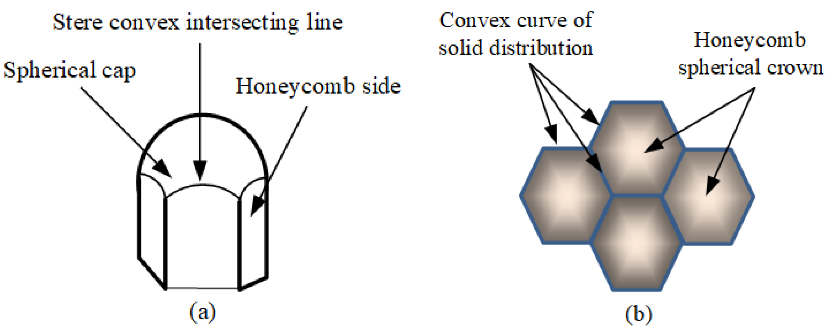
2.1. Structure Form

Because of its high hardness, high strength, high wear resistance, corrosion resistance, and small density, ceramic is widely used as a lightweight armor material, but, at the same time, ceramic formation is smaller, and it has shortages regarding its toughness and low fracture strength. These features mean ceramics are usually not a homogeneous bulletproof material application on their own but are combined with other materials to form composite materials using composite. Many scholars [3,12,14] have studied the elastic resistance of ceramic panels made of a variety of monomer ceramic tiles, and the consistent conclusion is that honeycomb ceramic panels have better elastic resistance. Similarly, there are many studies [6] on ceramic oblique penetration, and the consistent conclusion is that ceramic plates of the same thickness have better damage resistance within a certain range of projectile antenna. However, many of the above studies either simply considered the performance advantages of a honeycomb structure or only studied the local oblique penetration of the ceramic surface. The research on the above-mentioned “oblique penetration” anti-ballistic performance can be summarized into a so-called “projectile model”, as shown in Figure 1.
Obviously, the flaw in this design is the presence of non-oblique penetration zones, and for bulletproof structures, the presence of weak zones is fatal. In order to overcome this inadmissible structural problem, a structure is designed as shown in Figure 2.
The design of this structure eliminates the defect of non-oblique penetration in the plane curve and the triangular area of the “projectile structure”, while also taking into account the bulletproof advantage of the honeycomb structure.
Considering the advantages of the elastic resistance of the two structures, the optimized structural design can realize the honeycomb ceramic structure with nominal forward penetration and the actual contact target is full-domain oblique penetration.

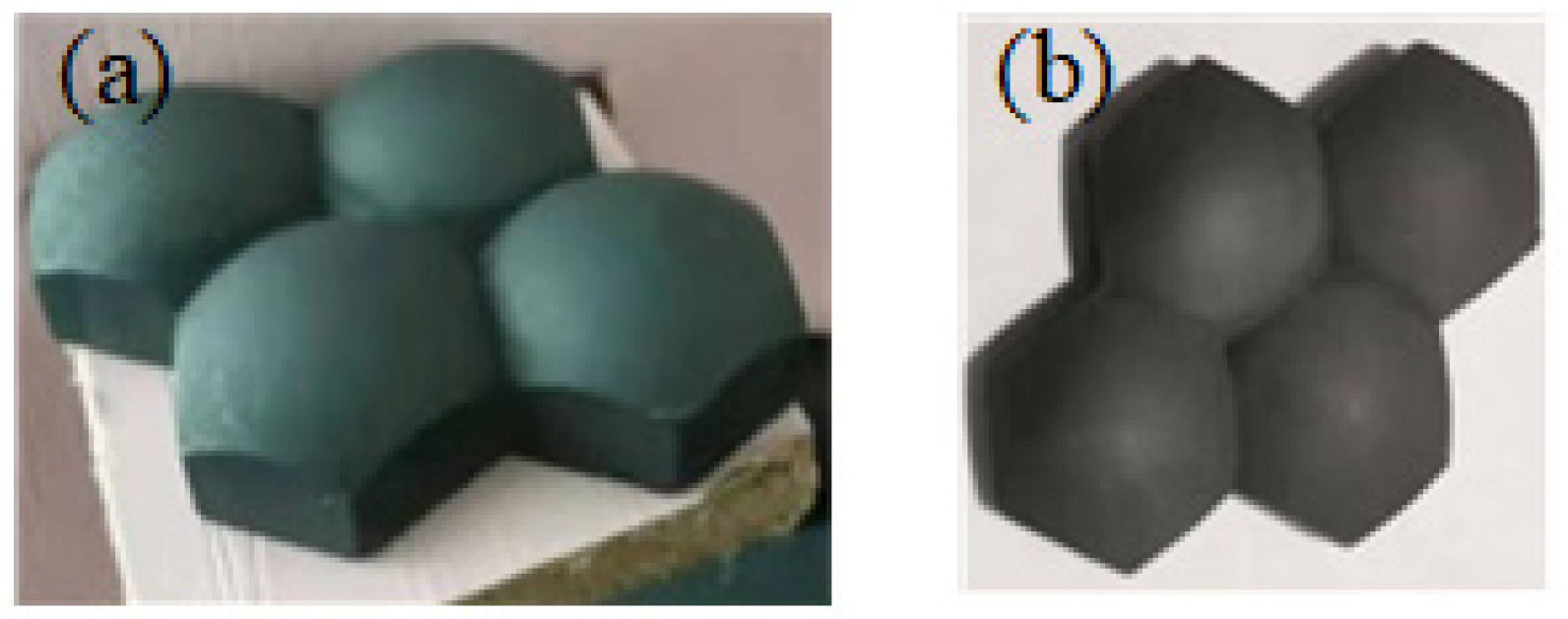
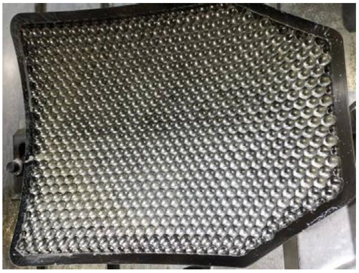
2.2. Monomer, Splice, and Monolithic Ceramic Structure

As the basic structure of the ceramic body, the ceramic monomer is designed as an intersecting body of a hexagonal prism and a sphere, which should have the function of converting the incident angle of the warhead into actual oblique penetration. The specific structural form is described in Figure 3.
It can be seen from Figure 3 that the intersecting line of a monomer is an upward convex curve, the projectile facing surface is a sphere with appropriate curvature, and the hexagonal prism part is a honeycomb matrix, whose bottom surface can be flat or curved to adapt to different backplane surfaces. To construct a splicing ceramic body from the monomer, it only needs to splice the single ceramic pieces of the multi-monomer into a large area according to the honeycomb structure, and then process the matching of the ceramic panel boundary using the monomer and semi-monomer ceramic pieces. According to the momentum principle, in order to match the mass of the warhead, the single-chip ceramics should be modeled and sintered by the combination of multiple monomers to increase the impact shear resistance of the ceramic sheet against the warhead. Figure 3b is a photo of the 4-coupled ceramic sheet. During the preparation of ceramic samples, four ceramic sheet molds, monomer molds, and semi-monomer molds are prepared. The last two sets of molds are prepared to deal with the boundary problem of the plate. The preparation of the ceramic sheet is formed by atmospheric sintering; its technical route is as follows: ceramic powder is pressed billet, and then it undergoes atmospheric sintering. This also provides a path for mass production of ceramic tiles. If the whole sintered ceramic plate is needed, only the single honeycomb structure, such as the skin modeling, mold opening, pressing, and sintering, of the honeycomb ceramic plate can be prepared. Figure 4 is the upper die of the multi-curved honeycomb plate. At the same time, due to the weight reduction and bulletproof performance of the honeycomb ceramic body, compared with the bulletproof performance of the existing bulletproof inserts, the areal density of the sample inserts is lower, and the mass of the same specification of the insert board is about 200 g less. The weight reduction effect and the improvement in the ballistic resistance obtained by the test are not due to the type and material of the ceramic but the shape and structure. Therefore, no new process is required to prepare the ceramic composite bulletproof equipment of this structure, which not only ensures the safety of the bulletproof vest performance but also means that the cost will not increase.

2.3. Material Selection for Panels and Backboards

Aluminum oxide, silicon carbide, silicon nitride, and boron carbide are common bulletproof ceramic materials [5,6,7,8,9,10]. Their high elastic modulus, high hardness, and low density of bulletproof performance indicators, including the high elastic modulus and high hardness of boron carbide, can make the bullet play a role in the invulnerability injury effectiveness in the process of penetration and absorb the kinetic energy of the warhead in the process of oblique penetration, broken shells, and the plough cut projectile cone. Its minimum density meets the lightweight requirements of armor for bulletproof materials. Boron carbide ceramic is used as bulletproof panel material in this study.
The main function of the backplane is to support the confinement ceramic panel and absorb the residual kinetic energy of the warhead. Therefore, the backplane material should have high stiffness, strength, and toughness to ensure that it can prevent the impact of ceramic fragments and broken shrapnel. From the performance index study of several common backplane materials, it can be seen that the bulletproof performance of a hard fiber backplane is much higher than that of a metal backplane [4,5,6,7,8,9,10,11,12,13,14]. In this study, a UHMWPE fiber composite material is used as the backplane to meet the lightweight requirements of composite armor.

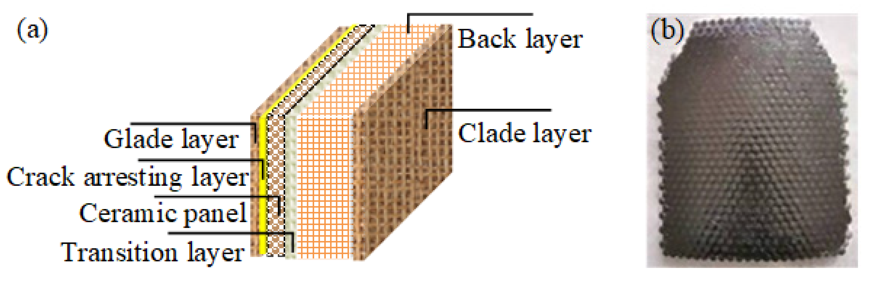
2.4. Preparation of Ceramic/Fiber Composite Armor

In order to carry out the targeted test, this study adopts a single soldier insert plate as the detection object of ceramic/fiber composite armor, and adopts a mainstream splicing ceramic panel and PE backplane with a multi-curved shape. The splicing ceramic unit comprises four single ceramic pieces as shown in Figure 1. The four monomer ceramic pieces were obtained from China Ningxia Machinery Research Institute Co., Ltd., and the PE backplane was provided by China Hunan Zhongtai Special Equipment Co., Ltd. The physical properties of the boron carbide ceramic materials are shown in Table 1, and the physical properties of the PE backplane materials are shown in Table 2.
A Kevlar layer is arranged between the panel and the backplane, which is bonded with special PE adhesive provided by Dongguan Jinggu Gum Co., Ltd., Dongguan, China. The honeycomb surface layer of the panel is filled with hot melt adhesive. Finally, the surface of the panel is covered with Kevlar cloth and PE adhesive, as shown in Figure 5.

3. Test Conditions and Methods

The test site was the test center of Ordnance Equipment Research Institute, and the test was based on GA141-2010 Police Body Armor and NIJ Standard-0101.6 Ballistic Resistance of Body Armor, respectively. In this paper, the defense capability of the ceramic composite target plate was studied using three types of projectiles (Type 53 7.62 mm armor-piercing incendiary projectile, 7.62 mm NATO (M80) projectile, and type 87 5.8 mm ordinary projectile). In order to compare the bulletproof performance of boron carbide and silicon carbide, two inserts were tested for various bullets. The backplane was a multi-curved PE backplane. The test results are shown in Table 3. The panel photos corresponding to the sample number after shooting and photos of the corresponding back convex of the rubber mud are shown in Figure 6.

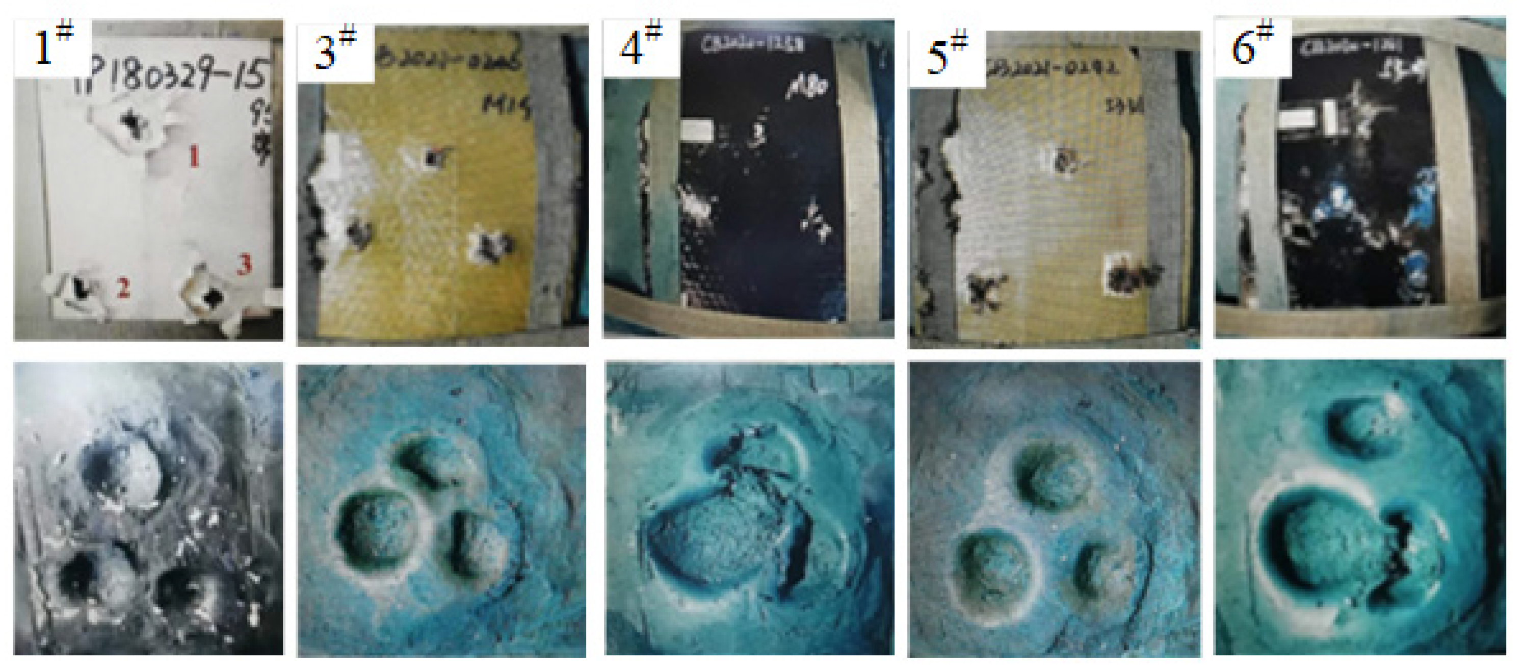
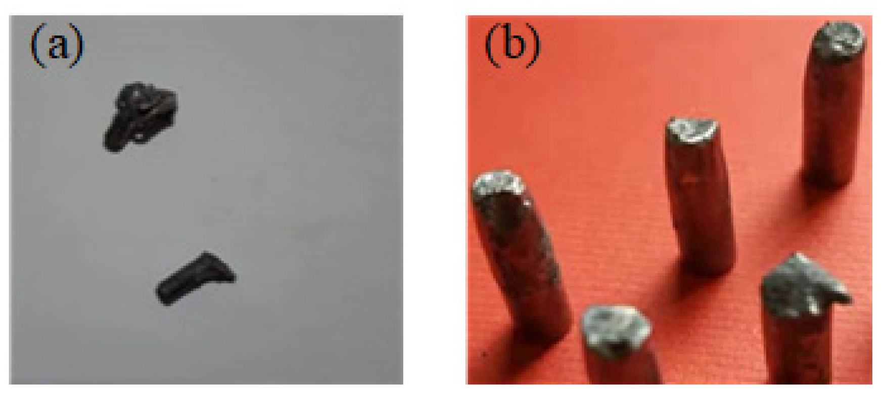
4. Results and Discussion

4.1. Analysis of Experimental Results

A total of 6 rounds of shells that penetrated the ceramic composite target plates were tested, including 2 rounds of 5.8 mm shells, 2 rounds of 7.62 mm NATO shells (M80), and 2 rounds of 7.62 mm 53 armor-piercing incendiary projectiles.
It can be seen from Table 3 that the 5.8 mm shell type 95 rifle shoots composite panels with 6 mm boron carbide panels and a 10 mm PE backplane, and its bulletproof performance meets the level 6 requirements of GA141-2010 Police Body Armor, while the composite panels with a 5 mm silicon carbide backplane and 12 mm PE backplane were penetrated in the third round. This means that the ceramic plate is not thick enough to withstand the impact of a warhead. Two 7.62 mm NATO shells, fired from an M14 7.62 mm automatic rifle, failed to penetrate the target plate, and the back convex of the boron carbide ceramic composite target plate was smaller than that of the silicon carbide ceramic composite target plate. However, their bulletproof performance meets NIJ Standard-0101.6 Ballistic Resistance of Body Armor grade iii requirements. Two rounds of 7.62 mm 53 penetrating bullets were fired by a 7.62 mm ballistic gun but failed to penetrate the target plate. Similarly, the dorsal convex of the boron carbide ceramic composite target plate is smaller than that of the silicon carbide ceramic composite target plate. However, their bulletproof performance meets the requirements of NIJ Standard-0101.6 Ballistic Resistance of Body Armor grade iv.
A comparative analysis of the test data is shown in Table 1 and the target test data of the conventional ceramic panel shows that the target surface density of the ceramic composite panel composed of the ceramic and PE plate with the same thickness in this test is low, and the back convex after the target test is small.
The partial recovery pattern of the type 87 5.8 mm shell is shown in Figure 7.
As can be seen from the damage morphology analysis of the projectile steel cone in Figure 7a, there are obvious fracture marks on the cone tip, which is different from the plough morphology of the penetrating cone head because of oblique penetration of the warhead. The impact angle of the projectile point on the ceramic surface is non-0°, and the impact is asymmetric. The ceramic surface has a transverse component force on the projectile, forming a rotational bending moment on the projectile axis, which will produce a tensile stress region in the projectile cone. When the tensile stress exceeds the tensile strength of the projectile material, the cone head will break. From the perspective of kinematics, the projectile will yaw during penetration. These two aspects of performance will increase the bulletproof performance of ceramic panels. Figure 7b shows a photograph of the warhead core embedded in the triangular region of the four-couplet ceramic. This triangle is the intersection of the three spherical crowns and has a maximum solid angle of 25° compared with the normal cone angle of 40°. Therefore, the steel cone has to intercept and trap at least two spherical crowns during the penetration process.

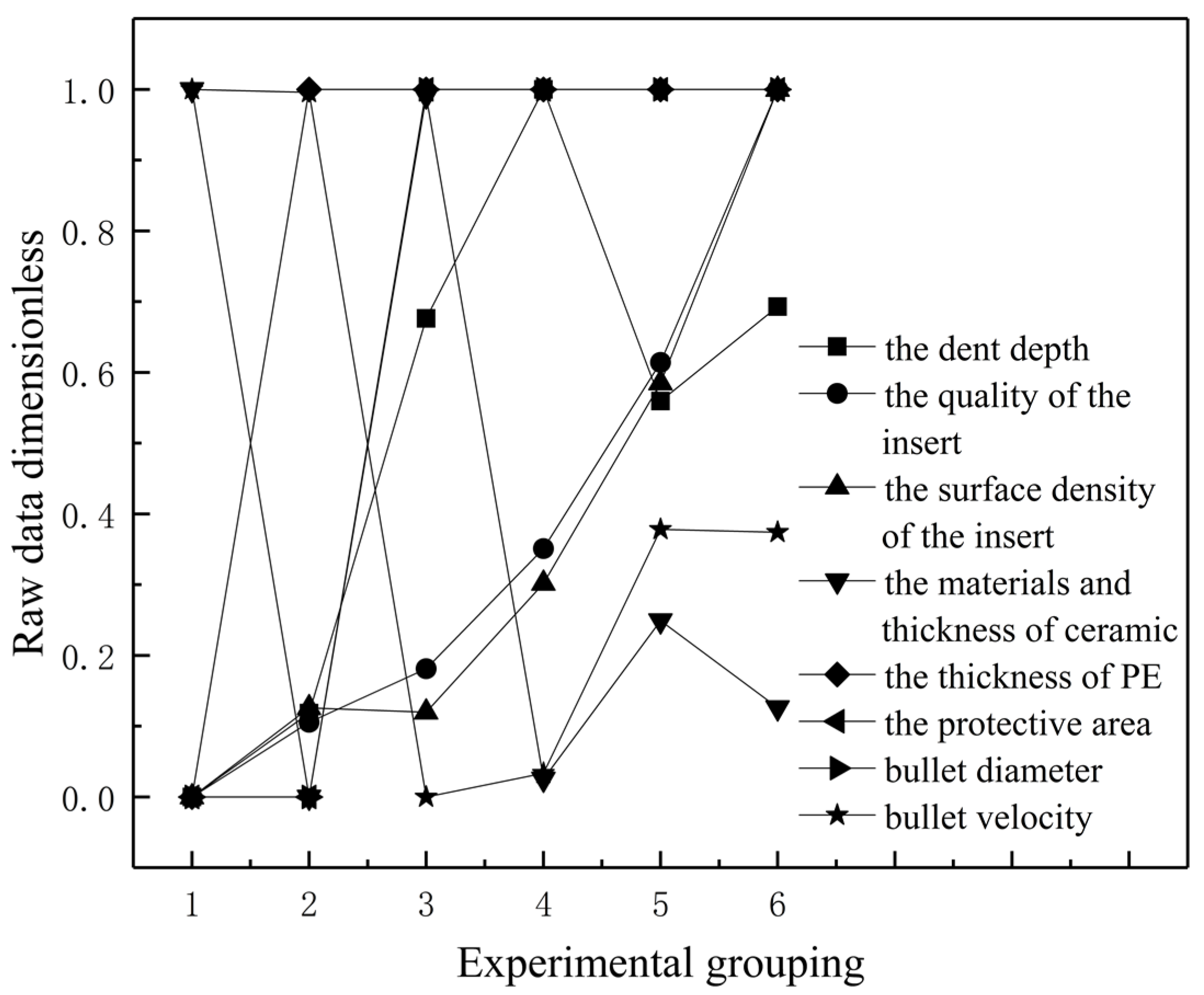
4.2. Correlation Analysis of the Influencing Factors of Shells Penetrating Ceramic Composite Target Plates

It can be seen from Table 3 that under different conditions, the quality of the insert, surface density of the insert, thickness of the ceramic, thickness of PE, protective area, bullet diameter, and bullet velocity have an important impact on the defense capability of the ceramic composite target. However, the primary and secondary roles of the influencing factors are not clear. This paper takes the statistical data of the six-shot penetrating ceramic composite target plate test as an example. The penetration situation and the dent depth of the backing material are used as the evaluation criteria for the defense ability, and fuzzy gray correlation analysis is carried out on the influencing factors.

4.2.1. Establishment of the Fuzzy Grey Relational Analysis Model

Fuzzy grey analysis starts from things with fuzzy boundaries and uses the multivariate analysis method in mathematical statistics to analyze the degree of correlation between the research objects [22]. Grey correlation analysis is a method for comparing the correlation of incomplete information systems, and it can calculate the degree of the mutual influence of various factors [23]. Combining the advantages of the two analysis methods, and based on the angle cosine model of Dunn’s grey relational model and the principle of similarity, the displacement difference is used to reflect the similarity between sequences to analyze the influence degree of each factor. The specific steps are as follows:
(1)
Determine the analysis sequence
A reference sequence is a data sequence that reflects the characteristics of a system’s behavior, and it consists of different sets of statistical data that characterize the system’s behavior. Its manifestation is:
Y T = [ y t ( 1 ) y t ( 2 ) y t ( n ) ]
In the formula, YT represents the reference sequence in the t-th group, (T = 1,2,…, H), [yt(1) yt(2) … yt(n)] is the data in the reference sequence in the YT group, and these data are the response of the specific manifestation of this parameter change law.
The comparison sequence is a data sequence that affects the behavioral characteristics of the system, and is composed of influencing factors that show different behaviors. Its manifestation is:
X T = [ x t 1 ( 1 ) x t 1 ( 2 ) x t 1 ( n ) x t 2 ( 1 ) x t 2 ( 2 ) x t 2 ( n ) x t m ( 1 ) x t m ( 2 ) x t m ( n ) ]
In the formula, XT is the comparison sequence corresponding to the reference sequence YT, and there are m influencing factor vectors in this comparison sequence.
The j-th influencing factor vector is xtj, (j = 1, 2,…, m); there are n kinds of working conditions under the action of these influencing factors, and the kth working condition is marked as xtj(k), (k = 1, 2,…, n).
(2)
Dimensionless analysis sequence
Since the influencing factors in the system characterization process have different data dimensions, in order to reduce the resulting identification and analysis errors, the data interval and dimensionless transformation are adopted, which is equivalent to the range change in fuzzy clustering. Its formula is as follows:
X = (x(1) x(2) x(3)…x(n))
x ( k ) = x ( k ) min k ( k ) max k   x ( k ) min k   x ( k )
where k = 1, 2, 3,…, n.
(3)
Calculation of fuzzy membership
The angle cosine method that is not subject to the linear proportional relationship of the data is used to calculate the angle cosine between the two parameters, and the similarity between the two is obtained. Its formula is as follows:
r t j = k = 1 n y t k x j k k = 1 n y t k 2 k = 1 n x j k 2
(4)
Calculation of the grey correlation coefficient
In the analysis model of the influence factors of the shells penetrating the ceramic composite target plates, all the reference sequences and the comparison sequences are subjected to the difference operation, and the following grey correlation coefficient calculation formula can be used:
ξ t j ( k ) = Δ min + ρ Δ max Δ t j ( k ) + ρ Δ max
where ξtj is the correlation coefficient between the reference sequence and the two corresponding points in the comparison sequence (j = 1, 2,…, m; k = 1, 2, …, n) and Δmin and Δmax are the minimum absolute difference and the maximum absolute difference between the corresponding elements in the reference sequence YT and the comparison sequence XT, respectively. Δtj(k) is the absolute difference between the k-th point of the reference sequence and the kth point of the comparison sequence, and ρ is the resolution coefficient.
The minimum absolute difference Δmin and the maximum absolute difference Δmax of the corresponding elements in the reference sequence YT and the comparison sequence XT are expressed as:
Δ min = min 1 j m min 1 k n y t ( k ) x t j ( k )
Δ max = max 1 j m max 1 k n y t ( k ) x t j ( k )
The expression of the absolute difference Δtj(k) between the kth point of the reference sequence and the kth point of the comparison sequence is:
Δ i j ( k ) = Y T ( k ) X r i ( k )
The essential meaning of the resolution coefficient ρ is the weight of the maximum absolute difference. The value of ρ should satisfy the integrity of the anti-interference and the correlation degree. If the value is too large or too small, it cannot correctly reflect the correlation between the research objects. The method of determining the resolution factor is as follows:
  • Step 1: Calculate the mean of all absolute differences:
    Δ ¯ = 1 n m j = 1 m k = 1 n y t ( k ) x t j ( k )
  • Step 2: Determine the value interval of the resolution coefficient ρ according to the ratio of the mean value of the absolute difference to the maximum absolute difference value; record EΔ = Δ ¯ max. The value interval of the resolution coefficient ρ is: EΔρ ≤ 2EΔ, and it needs satisfy:
    When   Δ max > 3 Δ ¯ ,   E Δ ρ 1.5 E Δ
    When   Δ max 3 Δ ¯ ,   1.5 E Δ ρ 2 E Δ
When Δmax > 3 Δ ¯ , it means that the sequence under study has abnormal values, and when Δmax ≤ 3 Δ ¯ , it means that the sequence under study is normal.
(5)
Disadvantages of European-style gray correlation
Correlation analysis is a quantitative comparative analysis of dynamic process development. In order to obtain more accurate results, the weighted grey relational degree is obtained by combining the weights with the relational coefficients. Its calculation formula is as follows:
r t j = 1 n w j k = 1 n ξ t j ( k )
(6)
Calculation of Fuzzy Gray Correlation Degree
Combining the fuzzy membership coefficient calculated by the angle cosine method with the gray correlation coefficient, a comprehensive index to define the torque influencing factors can be obtained; that is, the fuzzy correlation degree is:
R t j = ( r t j + r t j ) / 2 = ( k = 1 n y t k x j k k = 1 n y t k 2 k = 1 n x j k 2 + 1 n w j k = 1 n ξ t j ( k ) ) / 2

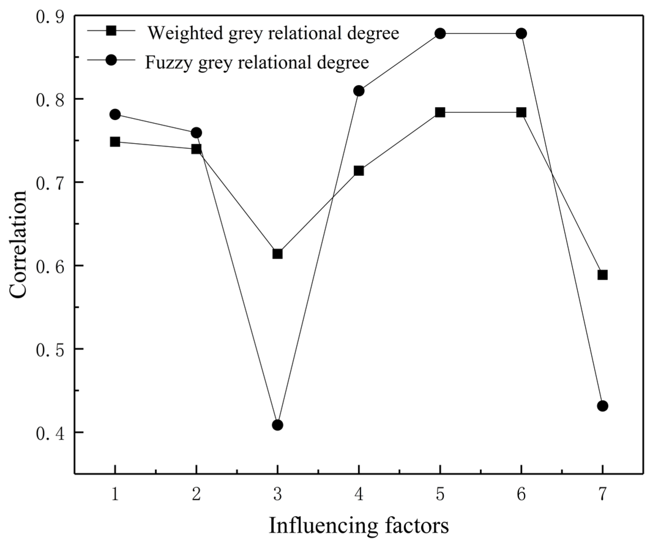
4.2.2. Correlation Analysis of the Factors Affecting the Penetration of the Standard Bullet into the Ceramic Composite Target

Based on the establishment of the above-mentioned fuzzy grey relational analysis model, in order to comprehensively analyze the hit situation and the dent depth of the backing material in the test of the standard bullet penetrating the ceramic composite target plate, the double test index problem is transformed into a single test index for evaluation. In the case of no penetration, the correction factor for the recessed depth of the backing material is 1, and in the case of penetration, the correction factor is 1.1. Each group of tests is repeated three times, and the average value of the backing material concave depth after three corrections is taken as the reference sequence; that is, the formula is as follows:
y ( k ) = i = 1 3 ( y i t ( k ) + 1.1 y i u ( k ) ) 3
where y(k) is the reference sequence, yit(k) is the recessed depth of the backing material that is not penetrated, and yi(k) is the maximum recessed depth of the backing material required in the case of penetration.
Taking y(k) as the reference sequence Y, the main factor of the depth of the material depression constitutes X. Among them, there are two kinds of ceramics: boron carbide and silicon carbide. The hardness of boron carbide is 48,542.92 MPa, and the hardness of silicon carbide is 32,630 MPa. The hardness ratio is 1.488, considering the different hardness of the two materials; that is, the conversion factor of the specified thickness of boron carbide ceramics is 1.488, and the conversion factor of the thickness of silicon carbide ceramics is 1. The influence of the bullet type mainly depends on the diameter of the warhead; that is, the diameter of the warhead is used as the influence coefficient. The bullet velocity is the average value of each group of tests. In summary, the following coefficient matrix can be obtained:
[ Y X ] = [ 113 6 106 5 97 3 194 5 30 98 3 1.79 1.97 2.1 2.39 2.84 3.5 23.87 26.37 26.25 29.87 35.5 43.75 1116 / 125 5 1116 / 125 6 372 / 25 10 10 12 12 12 12 12 0.075 0.075 0.08 0.08 0.08 0.08 5.8 5.8 7.62 7.62 7.62 7.62 924 924 845 847 875 875 ]
After dimensionless, the following coefficient matrix is obtained:
[ Y ( k ) X 1 ( k ) X 2 ( k ) X 3 ( k ) X 4 ( k ) X 5 ( k ) X 6 ( k ) X 7 ( k ) ] = [ 0 0.1185 0.6761 1 0.5593 0.6928 0 0.1053 0.1813 0.3509 0.6140 1.0000 0 0.1258 0.1197 0.3018 0.5850 1.0000 1.0000 0 0.0991 0.0252 0.2492 0.1261 0 1.0000 1.0000 1.0000 1.0000 1.0000 0 0 1.0000 1.0000 1.0000 1.0000 0 0 1.0000 1.0000 1.0000 1.0000 1.0000 0.9958 0 0.0336 0.3782 0.3739 ]
By analyzing the similarity of the geometric shapes of the curves in Figure 8, it is possible to roughly compare the impact of the bullet in the test of the bullet penetrating the ceramic composite target plate and the depth of the depression of the backing material. It can be seen that the curve of the influencing factors “ceramic thickness” and “warhead velocity” is quite different from the curve of the backing material’s concave depth, which shows that the factors of “ceramic thickness” and “warhead velocity” have little effect on the concave depth of the backing material. This method is more intuitive but imprecise.
By including the dimensionless coefficient matrix in Formula (5) for further analysis, the ambiguity membership degree of the influencing factors can be obtained, as shown in Table 4.
By including the dimensionless coefficient matrix in Formulas (7)–(9), Δmin = 0, Δmax = 1 can be calculated, and the absolute difference matrix between the reference sequence and the comparison sequence is:
[ Δ 1 ( k ) Δ 2 ( k ) Δ 3 ( k ) Δ 4 ( k ) Δ 5 ( k ) Δ 6 ( k ) Δ 7 ( k ) ] = [ 0 0.0133 0.4948 0.6491 0.0548 0.3072 0 0.0072 0.5564 0.6982 0.0275 0.3072 1.0000 0.1185 0.5770 0.9748 0.3100 0.5667 0 0.8815 0.3239 0 0.4407 0.3072 0 0.1185 0.3239 0 0.4407 0.3072 0 0.1185 0.3239 0 0.4407 0.3072 1.0000 0.8873 0.6761 0.9620 0.1811 0.3189 ]
By including the above absolute difference matrix in Formula (10), the mean value of all absolute differences Δ ¯ = 0.3575 , E Δ = Δ ¯ Δ max = 0.3575 ; then, the value range of ρ is: 0.3575 ≤ ρ ≤ 0.7150. It can be seen that Δmax < 3 Δ ¯ ; that is, the sequence data under study is normal, so this paper takes ρ = 1.75 ∗ E Δ = 0.625625.
By including the above results in Formula (6), the gray correlation coefficient matrix of each factor pair can be obtained:
[ ξ 1 ξ 2 ξ 3 ξ 4 ξ 5 ξ 6 ξ 7 ] = [ 1.0000 0.9792 0.5584 0.4908 0.9195 0.6707 1.0000 0.9886 0.5293 0.4726 0.9605 0.6707 0.3848 0.8407 0.5202 0.3909 0.6686 0.5247 1.0000 0.4151 0.6589 1.0000 0.5867 0.6707 1.0000 0.8407 0.6589 1.0000 0.5867 0.6707 1.0000 0.8407 0.6589 1.0000 0.5867 0.6707 0.3848 0.4163 0.4806 0.3930 0.7755 0.6624 ]
By including the gray correlation coefficient matrix in Formula (13), the weighted gray correlation degree of each factor affecting the depth of the concave backing material can be obtained, and the fuzzy membership degree and weighted gray correlation degree can be substituted in Formula (14) to obtain the fuzzy gray correlation degree of the influencing factors, as shown in Table 5. The polyline of the two is shown in Figure 9.
After sorting, R5 = R6 > R4 > R1 > R2 > R7 > R3, which represents the protection area, bullet type, PE thickness, plate quality, plate surface density, warhead speed, ceramic material, and thickness. It can be seen that the “protection area” and “bullet type” are the main factors affecting the dent depth of the backing material while the “ceramic material and thickness” and “bullet velocity” have little effect on it, which is consistent with the analysis results shown in Figure 8.

5. Conclusions

Based on the structural design of the ceramic panel in ceramic/fiber composite armor, this study prepared a ceramic splice panel with the intersecting body of a hexagonal prism and sphere as the structural unit. Then, the corresponding ceramic/fiber composite inserts were prepared, and experimental studies were carried out. Based on the fuzzy grey correlation analysis model, fuzzy correlation degree analysis was carried out on the influencing factors of the defense capability of the ceramic composite target, and the following conclusions were finally obtained:
(1)
The bulletproof performance of the hexagonal prism ball-crown ceramic/fiber composite board was better than that of the conventional ceramic/fiber composite board of the same thickness.
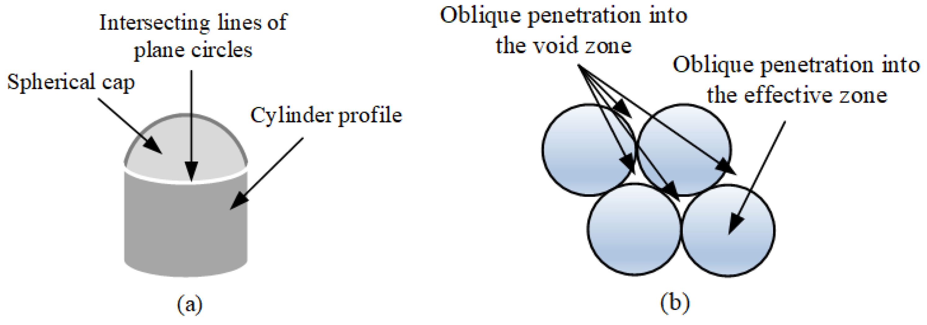
(2)
The hexagonal prism spherical cap ceramic panel can transform nominal forward penetration into actual oblique penetration.
(3)
The use of a hexagonal prism spherical cap ceramic panel is an effective way to achieve a lightweight design of ceramic/fiber composite armor.
(4)
The “protection area” and “bullet type” are the main factors affecting the dent depth of the backing material, while the “ceramic material and thickness” and “bullet velocity” have little effect on it.

Author Contributions

Conceptualization, J.C. and S.C.; methodology, Y.Z.; validation, X.L.; investigation, Y.H.; data curation, Y.W.; writing—original draft preparation, J.C.; writing—review and editing, S.C.; visualization, Z.S.; All authors have read and agreed to the published version of the manuscript.

Funding

This research was funded by Guangxi University of Science and Technology Doctoral (Grant No. 19Z27).

Acknowledgments

The authors gratefully acknowledge the financial support for this work from Guangxi University of Science and Technology Doctoral Fund.

Conflicts of Interest

The authors declare no conflict of interest.

References

  1. Shen, Z.; Hu, D.; Yang, G.; Han, X. Ballistic reliability study on SiC/UHMWPE composite armor against armor-piercing bullet. Compos. Struct. 2019, 213, 209–219. [Google Scholar] [CrossRef]
  2. Boldin, M.S.; Berendeev, N.N.; Melekhin, N.V.; Popov, A.A.; Nokhrin, A.V.; Chuvildeev, V.N. Review of ballistic performance of alumina: Comparison of alumina with silicon carbide and boron carbide. Ceram. Int. 2021, 47, 25201–25213. [Google Scholar] [CrossRef]
  3. Fawaz, Z.; Zheng, W.; Behdinan, K. Numerical simulation of normal and oblique ballistic impact on ceramic composite armours. Compos. Struct. 2004, 63, 387–395. [Google Scholar] [CrossRef]
  4. Clayton, J.D. Penetration resistance of armor ceramics: Dimensional analysis and property correlations. Int. J. Impact Eng. 2015, 85, 124–131. [Google Scholar] [CrossRef]
  5. Savio, S.G.; Ramanjaneyulu, K.; Madhu, V.; Bhat, T.B. An experimental study on ballistic performance of boron carbide tiles. Int. J. Impact Eng. 2011, 38, 535–541. [Google Scholar] [CrossRef]
  6. Zhai, Y.X.; Wu, H.; Fang, Q. Interface defeat studies of long-rod projectile impacting on ceramic targets. Def. Technol. 2020, 16, 19. [Google Scholar] [CrossRef]
  7. Madhu, V.; Ramanjaneyulu, K.; Bhat, T.B.; Gupta, N.K. An experimental study of penetration resistance of ceramic armour subjected to projectile impact. Int. J. Impact Eng. 2005, 32, 337–350. [Google Scholar] [CrossRef]
  8. Shokrieh, M.M.; Javadpour, G.H. Penetration analysis of a projectile in ceramic composite armor. Compos. Struct. 2008, 82, 269–276. [Google Scholar] [CrossRef]
  9. Zhang, Y.; Dong, H.; Liang, K.; Huang, Y. Impact simulation and ballistic analysis of B4C composite armour based on target plate tests—ScienceDirect. Ceram. Int. 2021, 47, 10035–10049. [Google Scholar] [CrossRef]
  10. Jiusti, J.; Kammer, E.H.; Neckel, L.; Lóh, N.J.; Trindade, W.; Silva, A.O.; Montedo, O.R.K.; de Noni, A. Ballistic performance of Al2O3 mosaic armors with gap-filling materials. Ceram. Int. 2017, 43, 2697–2704. [Google Scholar] [CrossRef]
  11. Ahn, B.K.; Curtin, W.A.; Parthasarathy, T.A.; Dutton, R.E. Criteria for crack deflection/penetration criteria for fiber-reinforced ceramic matrix composites. Compos. Sci. Technol. 1998, 58, 1775–1784. [Google Scholar] [CrossRef]
  12. Zhang, B.; Wang, Y.; Du, S.; Yang, Z.; Cheng, H.; Fan, Q. An analysis of bi-layer ceramic armor and optimization of protection efficiency. Mater. Des. 2021, 203, 109633. [Google Scholar] [CrossRef]
  13. Hu, P.; Cheng, Y.; Zhang, P.; Liu, J.; Yang, H.; Chen, J. A metal/UHMWPE/SiC multi-layered composite armor against ballistic impact of flat-nosed projectile. Ceram. Int. 2021, 47, 22497–22513. [Google Scholar] [CrossRef]
  14. Hu, D.Q.; Wang, J.R.; Yin, L.K.; Chen, Z.G.; Yi, R.C.; Lu, C.H. Experimental study on the penetration effect of ceramics composite projectile on ceramic/A3 steel compound targets. Def. Technol. 2017, 13, 7. [Google Scholar]
  15. Baha, T.; Ramazan, K. Ballistic performance of ceramic/composite structures. Ceram. Int. 2019, 45, 1651–1660. [Google Scholar]
  16. Zaera, R.; Sanchez-Galvez, V. Analytical modelling of normal and oblique ballistic impact on ceramic/metal lightweight armours. Int. J. Impact Eng. 1998, 21, 133–148. [Google Scholar] [CrossRef] [Green Version]
  17. Rahbek, D.B.; Simons, J.W.; Johnsen, B.B.; Kobayashi, T.; Shockey, D.A. Effect of composite covering on ballistic fracture damage development in ceramic plates. Int. J. Impact Eng. 2017, 99, 58–68. [Google Scholar] [CrossRef] [Green Version]
  18. Wang, W.Z.; Chen, Z.G.; Feng, S.S.; Zhao, T.Y. Experimental study on ceramic balls impact composite armor. Def. Technol. 2020, 16, 408–416. [Google Scholar] [CrossRef]
  19. Li, J.C.; Chen, X.W. Theoretical analysis of projectile-target interface defeat and transition to penetration by long rods due to oblique impacts of ceramic targets. Int. J. Impact Eng. 2017, 106, 53–63. [Google Scholar] [CrossRef]
  20. Chi, R.; Serjouei, A.; Sridhar, I.; Geoffrey, T.E. Pre-stress effect on confined ceramic armor ballistic performance. Int. J. Impact Eng. 2015, 84, 159–170. [Google Scholar] [CrossRef]
  21. Liu, W.; Chen, Z.; Cheng, X.; Wang, Y.; Amankwa, A.R.; Xu, J. Design and ballistic penetration of the ceramic composite armor. Compos. Part B Eng. 2016, 84, 33–40. [Google Scholar] [CrossRef]
  22. Wang, C.; Chen, S.F.; Yuen, M. Fuzzy Part Family Formation Based on Grey Relational Analysis. Int. J. Adv. Manuf. Technol. 2001, 18, 128–132. [Google Scholar] [CrossRef]
  23. Wang, G.; Wang, Y.; Liu, L.; Jin, Y.; Zhu, N.; Li, X.; Wang, G.; Chen, G. Comprehensive assessment of microbial aggregation characteristics of activated sludge bioreactors using fuzzy clustering analysis. Ecotoxicol. Environ. Saf. 2018, 162, 296–303. [Google Scholar] [CrossRef] [PubMed]
Figure 1. Schematic diagram of (a) the “projectile monomer” and (b) its combination.
Processes 10 01056 g001
Figure 2. Schematic diagram of (a) the “honeycomb monomer” and (b) its combination.
Processes 10 01056 g002
Figure 3. Photo of a 4-conjoined ceramic preform and sintered ceramic sheet at atmospheric pressure; (a) 4-conjoined ceramic billet; (b) sintered ceramic sheet at atmospheric pressure.
Processes 10 01056 g003
Figure 4. Upper die of the honeycomb ceramic slab with a multi-curved surface.
Processes 10 01056 g004
Figure 5. Schematic diagram of the ceramic composite insert plate and photos of the spliced ceramic composite insert plate sample. (a) Schematic diagram of the ceramic composite insert board. (b) Sample of the spliced ceramic composite insert plate.
Processes 10 01056 g005
Figure 6. Panel photos and the corresponding back convex photos of the rubber mud after the number-inserting board shooting.
Processes 10 01056 g006
Figure 7. Photo of the 5.8 mm projectile core recovered after the target test. (a) The 5.8 mm projectile steel core recovered after the target test. (b) Photo of the recovered sandwich steel core.
Processes 10 01056 g007
Figure 8. Sequence diagram of factors affecting the depth of the concave backing material (after dimensionless).
Processes 10 01056 g008
Figure 9. The weighted grey relational degree and fuzzy grey relational degree line chart of the influencing factors.
Processes 10 01056 g009
Table 1. Physical properties of boron carbide.
CeramicDensity (g·cm−3)Elasticity-ModulusHardness (HK)Fracture toughness (MPa·m1/2)
B4C2.5040029003.55
Table 2. Physical properties of PE backplane material.
UHMWPEDensity (g/m3)Modulus (G/dex)Strength (G/dex)Fracture Elongation (%)Areal Density (g/cm2)
ZT600.47401500 2.8 235   ± 5
Table 3. Material parameters of the rotating band.
NumberBoard Quality (kg)Board Surface Density (kg/m2)Ceramic Thickness (mm)PE Thickness (mm)Protection Area
(m2)
Range (m)
11.7923.876
boron carbide
100.07515
21.9726.375
Silicon carbide
120.07515
32.126.256
boron carbide
120.0815
42.3929.876
Silicon carbide
120.0815
52.8435.510
boron carbide
120.0815
63.543.7510
Silicon carbide
120.0815
Shot AngleAmmunition
(mm)
Shot
Sequence
Warhead
Velocity (m/s)
Shooting SituationBacking Material Recess Depth
Require
(mm)
Measured Value (mm)
Type 87 5.81926No penetration≤2518.3
2925No penetration21.0
3923No penetration17.2
Type 87 5.81925No penetration≤2515.1
2923No penetration21.0
3925Penetration/
7.62 NATO round (M80)1845No penetration≤4428.6
2844No penetration31.7
3847No penetration36.7
7.62 NATO round (M80)1847No penetration≤4438.5
2852No penetration36.7
3845No penetration41.2
Type 53 piercing bomb 7.621878No penetration≤4429.7
2873No penetration28.4
3875No penetration31.9
Type 53 piercing bomb 7.621877No penetration≤4426.7
2875No penetration32.4
3873No penetration38.9
Table 4. Fuzzy membership degrees of influencing factors.
X1X2X3X4X5X6X7
ri0.81410.77880.20320.90560.97310.97310.2741
Table 5. Weighted grey relational degree and fuzzy grey relational degree of the influencing factors.
X1X2X3X4X5X6X7
r i 0.74840.73970.61400.71370.78370.78370.5888
R i 0.78130.75930.40860.80960.87840.87840.4315
Publisher’s Note: MDPI stays neutral with regard to jurisdictional claims in published maps and institutional affiliations.

