1. Introduction
Production profile logging technology of Oil-water two-phase flow is an important support technology for efficient development of horizontal wells. It provides important key reference data for horizontal well stimulation implementation and effect evaluation, such as optimizing injection-production scheme, evaluating fracturing, water plugging, and profile modification effects. Moreover, the water holdup of Oil-water two-phase flow is one of the important dynamic measurement parameters for production profile logging technology. Flow patterns in horizontal oil wells are more complex than those in vertical oil wells, making water holdup measurements more difficult. At present, reliable production profile logging technology of Oil-water two-phase flow in the horizontal oil wells is still undeveloped in China.
Review the literatures published in the past thirty years, it is known that various conductance sensors are widely used for measuring water holdup and identifying flow pattern in Oil-water two-phase flow and gas-Oil-water three-phase flow. The double sensor conductivity probe method was used to measure local parameters in bubbly two-phase flow in horizontal pipe, the local void fraction, the local interfacial area concentration, and bubble interfacial velocity were measured and obtained [
1,
2,
3]. Ishill and Kim [
4] proposed the micro four-sensor conductivity probe for measuring local two-phase flow parameters in vertical upward annulus bubbles flow, and the experiments showed that the error of absolute measurement is less than 10%. Lucas and Mishra [
5] described the construction of a local four-sensor conductance probe and the associated electronic measurement circuit, for measuring the local axial, radial and azimuthal velocity components of the gas in bubbly gas-liquid vertical flows with and without swirl. Angeli and Hewitt [
6] investigated the flow pattern identification of Oil-water two-phase flow in horizontal pipes with 25.4 mm inner diameter; namely high-speed video recording and determination of the local phase fractions with a high frequency impedance probe, while the continuous phase in dispersed flows was recognized with a conductivity needle probe. Dong et al. [
7], Sun and Yang [
8], Fang et al. [
9] tried to measure separate phase fraction and distinguish flow pattern of Oil-water flows, gas-water flows, gas-Oil-water flows by using the single modality electrical capacitance tomography (ECT), electrical resistance tomography (ERT), or the dual-modality ECT/ERT, the accuracy of separate phase fraction measurement is highly dependent on the quality of image reconstruction.
For the purpose of developing reliable production profile logging instruments in the petroleum industry, Hu et al. [
10] firstly invented an impedance watercut meter which consists of four annular conductance sensors to measure water holdup in vertical oil wells, laboratory and field experiments proved that the water holdup measurement range and accuracy are 50~100% and 3%, respectively. Furthermore, Wang et al. [
11] optimized the measuring circuit of the meter that overcome artificial replacement of excitation source resistance caused by the salinity of downhole fluid varies widely. Xu et al. [
12] proposed a novel conductance sensor array for water holdup measurement in horizontal oil wells of low liquid production of oil and water, namely which consists of 24 needle-like electrodes that are mounted on 12 supporting arms arising from the central shaft. Han et al. [
13] used a radial dual-sensors conductance probe array to investigate flow patterns and water holdup in low velocity Oil-water two-phase flow through a vertical upward pipe with 20 mm inner diameter. Vu-Hoang et al. [
14] introduced a new logging tool to concretely obtain records of the holdups and velocity profiles along vertical direction of borehole, three types of array sensors consisted of five rotor flow sensors, six conductance probe sensors and six fiber probe sensors, are used to measure separate phase flow rate and holdup of gas, oil, and water. Liu et al. [
15] invented an annular array conductance sensor consisted of six annular electrodes for measuring the flow rate and water holdup of Oil-water two-phase flow in vertical production well. Han et al. [
16] presented using sixteen mini conductance probe sensors to measure the local oil holdup of oil-in-water emulsion flows of high water cut (80–96%) in vertical upward pipe. Zong et.al [
17] proposed using eight annular conductance sensors and five mini conductance probe sensors to study the inclined Oil-water two-phase flow characteristics. Xu et al. [
18] designed a bicircular conductance probe sensor array for measuring water holdup in simulation horizontal well for Oil-water two-phase flow.
It is very difficult to accurately measure water holdup due to the complex and variable flow patterns of Oil-water two-phase flow in horizontal oil wells affected by borehole inclination. In early literatures, it is known that the water holdup measurement of Oil-water two-phase flow is affected by flow pattern, which in turn is affected by pipe inclined angle. Mukherjee et al. [
19] researched pipe inclination angle effect to water holdup and Oil-water slippage in 38.1 mm inner diameter pipe for inclination angel ranged from ±30° to ±90°. Hill and Oolman [
20] studied simulation well inclination angel effect to production profile logging tool response in 152 mm inner diameter pipe. Zavareh et al. [
21], Davarzani et al. [
22], Tabeling et al. [
23], Oddie et al. [
24], Lum et al. [
25] studied the pipe inclination angel effect to flow patterns of Oil-water two-phase flow. As for water holdup measurement method of Oil-water two-phase flow, annular conductance sensor is suitable for more flow patterns than conductance probe sensor. However, since there is a serious problem in the field application of production profile logging of horizontal oil wells, i.e., the measurement error of water holdup increases due to the failure of the annular array conductance sensor to correct the influence of temperature and mineralization degree of groundwater in real time [
26]. Therefore, we proposed a novel method of measuring water holdup of Oil-water two-phase flow in horizontal oil wells. Then, we conducted the dynamic test by using the test prototype of the water holdup measurement method of Oil-water two-phase flow on the horizontal well simulation experimental device at five inclination angles. Finally, we analyzed the experimental phenomena and calculated the measurement error of the water holdup. The research results indicate that the novel method of measuring the water holdup of Oil-water two-phase flow in horizontal oil wells is a simple and accurate measurement method.
2. Measurement Principle of Water Holdup
In the production profile logging area, “water cut” and “water holdup” are commonly used terms, which are defined in reference [
27]. The geometry structure of water holdup measurement sensors of Oil-water two-phase flow in horizontal oil well is shown in
Figure 1, including annular array conductance sensor A and circumferential array conductance probe sensor B. The inner diameter of the sensor measuring channel is 20 mm. The annular array conductance sensor A consists of four annular conductance electrodes, thereinto, electrodes 1 and 4 are excitation electrodes, electrodes 2 and 3 are measurement electrodes. The inner diameter of each annular conductance electrode is 20 mm, and its thickness and width are 3 mm and 5 mm, respectively. The distance between electrodes 1 and 2 and between 3 and 4 is 80 mm for both. The distance between electrodes 2 and 3 is 50 mm. The distance between sensor A and sensor B is 60 mm in flow direction. The circumferential array conductance probe sensor B consists of four cylindrical conductance probes, for which the outer diameter of each cylindrical conductance probe is 3 mm, and its height is 5 mm. Each electrode is arranged at center angle 90° to its neighbor electrode.
The schematic diagram of water holdup test prototype of horizontal oil well in casing pipe is shown in
Figure 2, including petal type concentrating flow diverter, water holdup sensors, centralizer and measuring circuit. The measurement principle of water holdup is described as follows: The inner diameter of casing pipe is 125 mm, and the Oil-water two-phase flow flows in the casing pipe. Firstly, the measuring circuit controls petal type concentrating flow diverter to open, the annular space between the test prototype and the casing pipe is enclosed. The Oil-water two-phase fluid flows into the measurement channel of the water holdup sensors by the inlet of the petal type concentrating flow diverter. The mixed-phase conductivity (
) of Oil-water two-phase flow is measured by the annular array conductance sensor A. The specific measurement process is described as follows: The annular conductance sensor 1 and 4 are set as exciting electrodes; and the annular conductance sensor 2 and 3 are set as detecting electrodes, and the corresponding output voltage of detecting electrodes is
. Additionally, then the measuring circuit controls petal type concentrating flow diverter to close. The Oil-water two-phase fluid stratifies within the measurement channel of the water holdup sensors due to gravity. The water phase conductivity (
) is measured by the circumferential array conductance probe sensor B. The specific measurement process is described as follows: firstly, the instrument enclosure is set as ground electrode; then, four pairs of exciting-detecting electrodes are formed by four conductance probe sensors and the instrument enclosure; once the measuring circuit determines that one of the four exciting-detecting electrodes is flooded with water, therefore it can be used to measure the water-phase conductivity; additionally, the corresponding output voltage of exciting-detecting electrodes is
. The water holdup (
) of Oil-water two-phase flow can be obtained by the following Equation (1):
In order to obtain the water cut of Oil-water two-phase flow, it is necessary to calibrate the test prototype under the condition of Oil-water two-phase flow on the multiphase flow experimental device of the horizontal simulation well, and obtain the water cut–water holdup calibration chart; furthermore, water holdup can be converted to water cut through the calibration chart.
3. Experiments and Discussion
On the innovative horizontal well simulation facility, the Oil-water two-phase flow experiment was carried out by using the test prototype. Firstly, the horizontal well simulation facility was introduced. Secondly, the experimental method was described. Then, the experimental results and phenomena were discussed in detail. Finally, the measurement error of water holdup was calculated and evaluated.
3.1. Experimental Facility
The horizontal well simulation facility of Oil-water two-phase flow is located at the Daqing Production Well Logging Institute (DPWLI) in Heilongjiang Province of China. The schematic diagram of the flow loop is shown in
Figure 3. As shown in
Figure 3, the 125 mm inner diameter transparent Plexiglass pipes are 12 m long, which can be inclined from vertical direction to horizontal direction. In order to simulate the industrial application, the transparent Plexiglass pipes has the same diameter as the casing pipe. The flow rates of oil and water phase can be accurately controlled and metered using adjustment devices and measuring instruments. In addition, the experiments of Oil-water two-phase flow at any inclined angle can be carried out on the horizontal well simulation facility at normal pressure and temperature. More details of the experimental facility are provided in references [
27,
28].
Figure 4 shows the photo of the horizontal well simulation facility of Oil-water two-phase flow.
3.2. Experimental Design
The dynamic experiments of water holdup measurement of Oil-water two-phase flow were carried out by using the test prototype on the horizontal well simulation facility at the DPWLI, in Heilongjiang Province of China. The experimental mediums are tap water and diesel. The diesel density, kinematic viscosity, and interfacial tension are 820.0 kg/m3, 7.0 mm2/s and 28.6 mN/m, respectively, at 20 °C. The total flow rate of Oil-water two-phase flow is set as 3 m3/d, 5 m3/d, 10 m3/d, 30 m3/d, 40 m3/d, 60 m3/d, 100 m3/d, 120 m3/d, 150 m3/d and 200 m3/d, respectively. For each of the total flow rate, the water cut ranged from 30% to 90%, and the water cut adjust step is 10%. The inclination angle of horizontal simulation well is rotated clockwise, and the vertical direction and the horizontal direction are defined as 0° and 90°, respectively. The inclination angle is set as 80°, 83°, 85°, 88° (fluid flows upward) and 90° (fluid flows horizontally), respectively.
When the total flow rate is greater than 30 m3/d, after adjusting the water cut, the flow stable for 10 min before open the petal type concentrating flow diverter. Instead, when the total flow rate is less than 30 m3/d, after adjusting the water cut, the flow stable for 30 min before open the petal type concentrating flow diverter. After the petal type concentrating flow diverter is fully opened, continue the flow stable for 3 min, then start to measure the conductivity of Oil-water two-phase flow. The measurement time is set as 3 min, and two data are collected every second. Hence, a total of 360 instantaneous conductivity measurement data of the Oil-water two-phase flow are collected. Furthermore, starting to measure the conductivity of the water phase while the petal type concentrating flow diverter is fully closed. Similarly, the measurement time is set as 3 min, and two data are collected every second. Hence, a total of 360 instantaneous conductivity measurement data of the water phase are collected.
3.3. Discussions of Experimental Results
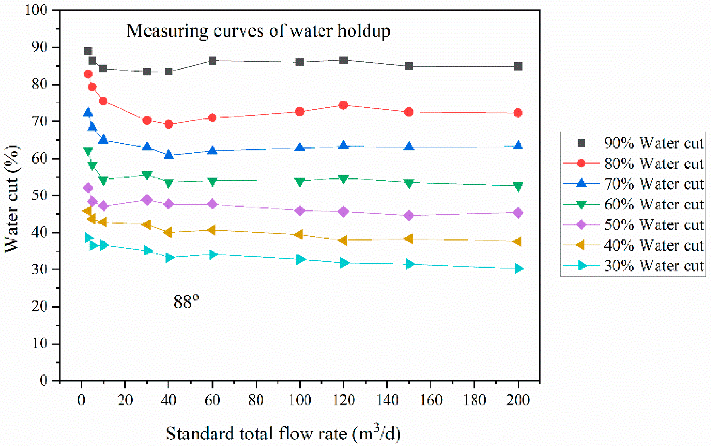
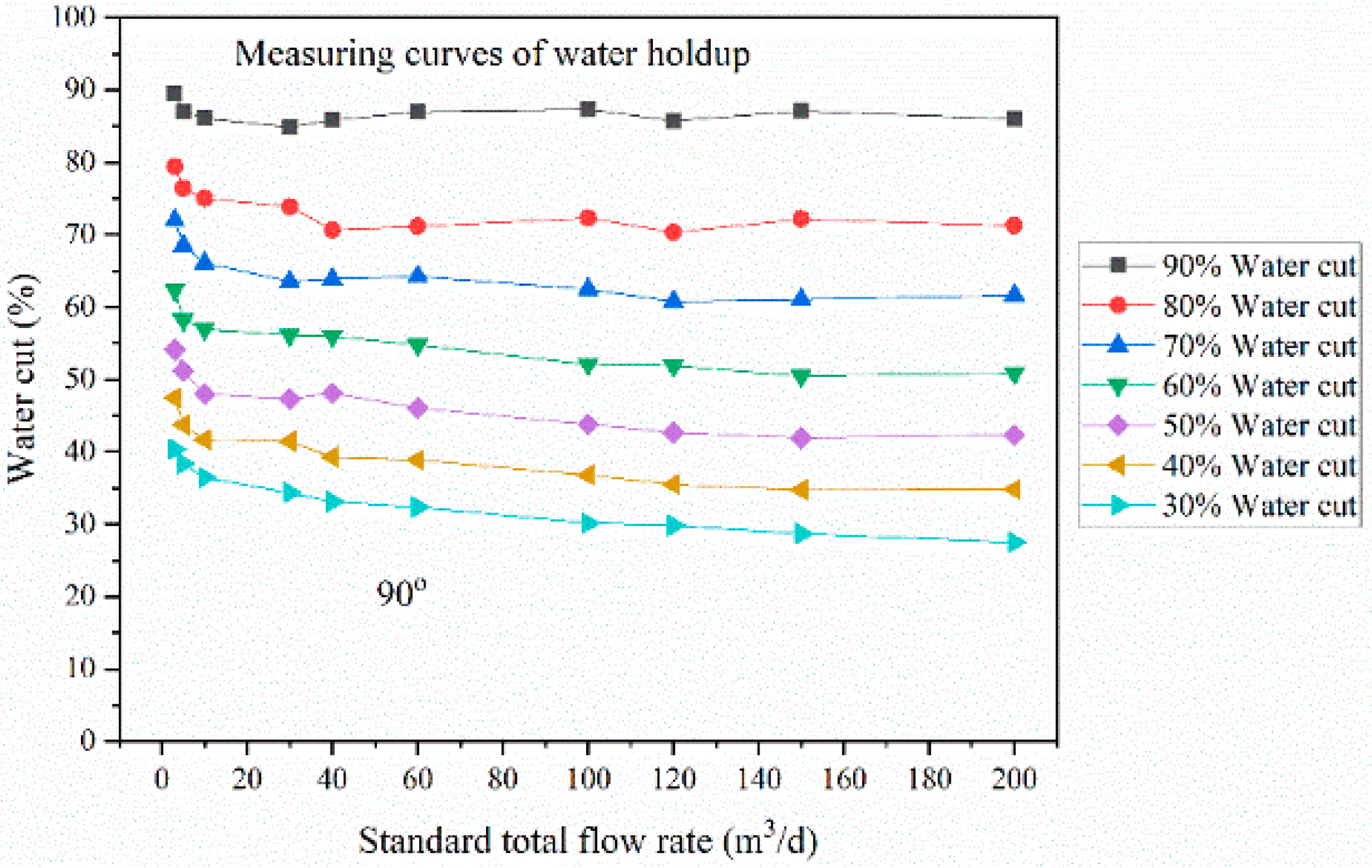
Figure 5,
Figure 6,
Figure 7,
Figure 8 and
Figure 9 shows the water holdup measurement charts with different flow rates and water cuts under the conditions of the horizontal simulation well inclination angle of 80°, 83°, 85°, 88° and 90°, respectively. The horizontal and vertical coordinates are the set standard flow rate and water cut, respectively, and curves in different colors represent measured water holdup. From the five figures, it indicated that the measurement result of water holdup is not only dependent on the water cut, but also related to the flow rate. The shape of water holdup curves measured at five inclined angles has good consistency. Further analysis of water holdup measurement charts at different inclined angles shows that the relationship between measured water holdup and set standard water cut has obvious regularity. In the low flow rates range, that is, when the total flow rates of oil and water two-phase flow are less than 30 m
3/d, the measured water holdups are not only dependent on the water cuts, but also related to the flow rates. When the set standard water cut remains unchanged, the measured water holdup moves to the direction of high water cut with the decrease in the flow rate. This phenomenon is caused by the Oil-water two-phase flow characteristics. Due to the density difference between the oil and water phase, the oil phase flows at a higher speed than the water phase. Therefore, under the condition of maintaining a certain set standard water cut, the measured water holdup at low flow rate is higher than that at high flow rate. With the decrease in the average flow rate of Oil-water two-phase flow, the difference of oil and water slippage velocity increases compared with the average velocity, especially when the total flow rate is less than 10 m
3/d, the slippage phenomenon is more significant, resulting in the difference between water holdup and water cut becoming larger. At present, other types of instruments of measuring horizontal oil well water holdup in use have difficulty reflecting the slippage phenomenon of Oil-water two-phase flow at low flow rates. For example, for the capacitive water holdup instruments, it is difficult to obtain accurate water holdup and water cut measurement curves because the capacitive electrode is easily affected by oil phase contamination. However, the water holdup measurement method by the combination of annular array conductance sensor and circumferential array conductance probe sensor proposed in this paper can better reflect the Oil-water slippage phenomenon at low flow rates. It indicates that the water holdup measurement method has obvious advantages at low flow rates of Oil-water two-phase flow.
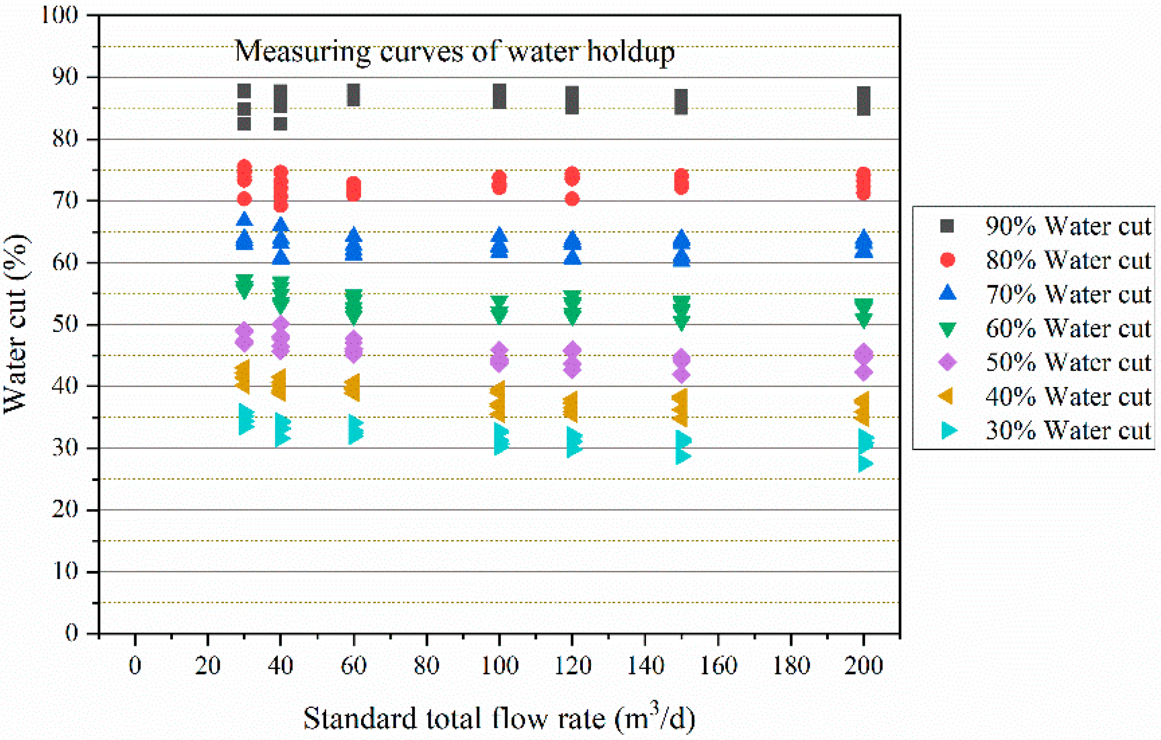
In order to further investigate the influence of horizontal simulation well inclination angles on water holdup measurement at high flow rates, the water holdup measurement chart of five inclination angles is given in
Figure 10, while the set standard flow rate ranged from 60 m
3/d to 200 m
3/d, and the set standard water cut ranged from 30% to 90%. It can be seen that the measured water holdup and the standard water cuts are approximately flat curves when the total flow rate is greater than 60 m
3/d and 100 m
3/d, and the standard water cut is greater than 60% and 30%, respectively. Because the oil and water slippage velocity rather small compared with the total average velocity. Therefore, the variation of flow rate has little influence on the water holdup measurement. At this time, the water holdup is very close to the water cut in the test prototype flow channel. The inclination angles have little influence on the water holdup measurement data of the test prototype and can be ignored. However, when the total flow rate of Oil-water two-phase flow is less than 60 m
3/d, the water holdup measurement data of the test prototype is greatly affected by the inclination angles and cannot be ignored. Therefore, the wellbore inclination angle measurement module should be included in the development of horizontal oil well production profile logging combination instrument, and the well logging interpretation model of different inclination angles must be established.
3.4. Error Calculation of Water Holdup
Furthermore, the measurement error of water holdup was evaluated. Due to the existence of random error, the measured values in the measurement column of equal accuracy are generally different, and they are dispersed around the arithmetic mean value of the measurement column to a certain extent. The degree of dispersion indicates the unreliability of the single measured value, and the standard deviation is used as the evaluation standard for evaluating unreliability. The specific process of error calculation of water holdup is described as follows:
(1) For a set standard flow rate, the average values of Oil-water mixed-phase conductivity and water phase conductivity measured by the test prototype are calculated, while the set standard water cut is 30%, 40%, 50%, 60%, 70%, 80% and 90%:
where
is the instantaneous measurement value of mixed-phase conductivity, and
is the average measurement value of mixed-phase conductivity.
where
is the instantaneous measurement value of water phase conductivity, and
is the average measurement value of water phase conductivity.
(2) The water holdup measured by the test prototype is calculated:
where
is the measurement value of water holdup.
(3) The standard deviation of mixed-phase conductivity and water phase conductivity are calculated:
where
is the standard deviation of mixed-phase conductivity.
where
is the standard deviation of water phase conductivity.
(4) The absolute value of measurement error of water holdup is calculated:
where
is the absolute value of water holdup measurement error.
The calculation results show that the absolute values of water holdup measurement error are less than 5% under the conditions of five inclination angles, while the total flow rate ranged from 10 m3/d to 200 m3/d, and the water cut ranged from 30% to 90%, respectively. However, the absolute values of water holdup measurement error are greater than 5% and less than 12% under the conditions of five inclination angles, while the total flow rate ranged from 3 m3/d to 10 m3/d, and the water cut ranged from 30% to 90%, respectively.
4. Conclusions
In this paper, a novel method of measuring the water holdup of Oil-water two-phase flow in horizontal oil wells was proposed. An innovative horizontal well simulation facility was used to simulate Oil-water two-phase flow and the proposed method was verified. Hence, the new method indicated important engineering application value because it solved the serious problem of measuring water holdup by using annular conductivity sensors alone, i.e., the measurement error of water holdup increases due to the failure of the annular array conductance sensor to correct the influence of temperature and mineralization degree of groundwater in real time. The experiment was correctly designed, the results were good and competently discussed. The dynamic experiments of water holdup measurement of Oil-water two-phase flow were carried out by using the self-developed test prototype on the horizontal well simulation facility. The measurement data of water holdup of five inclination angles were analyzed in detail, and the analysis results show that the measurement data of water holdup are affected by the wellbore inclination angle. The error calculation results show that the absolute values of water holdup measurement error are less than 5% under the conditions of five inclination angles, while the total flow rate ranged from 10 m3/d to 200 m3/d, and the water cut ranged from 30% to 90%, respectively. The research results prove that the novel method of measuring the water holdup of Oil-water two-phase flow in horizontal oil wells is a reliable and accurate measurement method. Future work will continue, the measurement method of water holdup proposed in this paper will be applied in engineering, the wellbore inclination angle measurement module should be included in the development of logging instrument, and the well logging interpretation model of different inclination angle must be established.


 ,
, 