Article

Investigation into Hydraulic Fracture Propagation Behavior during Temporary Plugging and Diverting Fracturing in Coal Seam

State Key Laboratory of Petroleum Resources and Engineering, China University of Petroleum, Beijing 102249, China
*
Author to whom correspondence should be addressed.
Processes 2022, 10(4), 731; https://doi.org/10.3390/pr10040731
Submission received: 6 March 2022 / Revised: 4 April 2022 / Accepted: 6 April 2022 / Published: 10 April 2022

Abstract

:
Temporary plugging and diverting fracturing (TPDF) is widely used to improve the stimulation effectiveness in coal seam. To study the fracture propagation behavior during TPDF in coal formation, a series of laboratory hydraulic fracturing experiments were performed on natural coal samples. Based on the results of sample splitting and fracture reconstruction, the influences of horizontal stress difference and the size of temporary plugging agent (TPA) as well as the concentration of TPA on hydraulic fracture growth were analyzed. Experimental results show that TPDF is beneficial for improving the fracture complexity even under high stress difference of 8 MPa. When the TPA of small particle size (70/100 mesh) was applied, the primary fracture could not be fully blocked whereas increasing the particle size of TPA to 20/40 mesh tended to cause accumulation and bridging in the wellbore, resulting in an abnormally high fracturing pressure. TPA with particle size of 40/70 mesh tended to be a reasonable choice for the target formation, as it could form effective plugging in primary fractures and promote the generation of new fractures. Meanwhile, optimizing the concentration of TPA was also conducive to improving the plugging effectiveness. Effective temporary plugging can be achieved by using appropriate TPA of proper size and concentration, which varies with different treatment parameters and formations. Laboratory experiments are expected to provide guidance for the parameter optimization for TPDF in coal seam.

1. Introduction

Coalbed methane (CBM) is an abundant and widely distributed unconventional resource with great exploitation prospect [1,2,3]. Shizhuangnan block, located in the southern Qinshui basin, north China, is one of the pioneer areas for the exploration and development of CBM [4,5]. Generally, it is necessary to create a large-scale complex fracture network and increase gas production area to promote the desorption of CBM in coal seam. TPDF has been proven to be an effective way to enhance the complexity of the fracture network, which has been utilized in the development of CBM. TPDF is performed by adding TPA in the fracturing fluid and pumping it into downhole. TPA is a substance that can temporarily reduce formation permeability or temporarily block the perforation hole. The thin and dense temporary plugging zone can be formed quickly under the action of pressure difference (Figure 1), which can bear high pressure and promote fracture diverting. After a certain period of time, the plug can be removed by itself or manually [6,7]. Investigating the propagation behavior of hydraulic fractures during TPDF in coal seam is of great significance for the treatment parameters design.
Recently, the hydraulic fracture propagation behavior in coal seam has been systematically studied through laboratory hydraulic fracturing experiments. Bell and Jones [8] suggested that the existence of joints in coal seam will deflect the propagation path of hydraulic fractures. Abass et al. [9] found that under high horizontal stress difference, a single hydraulic fracture tends to form along the direction of maximum horizontal principal stress. Deng et al. [10] and Du et al. [11] systematically studied the effects of different geological and engineering factors on breakdown pressure and fracture geometry in coal formation. Yang et al. [12] studied the influence of in situ stress and interlayer properties fracture propagation behavior in coal seam. Zou et al. [13], Cheng et al. [14], and Zhang et al. [15] analyzed the differences of fracture propagation geometry under different horizontal stress difference coefficients. The results showed that small horizontal stress difference coefficient is conducive to the formation of complex fracture network. Moreover, the propagation behavior of diverted fractures has also been investigated recently [16,17,18]. He et al. suggested that TPDF is one of the most effective ways to accomplish the diversion of hydraulic fractures and increase the complexity of fracture network. Wang et al. [19] performed temporary plugging and refracturing experiments using degradable fiber as TPA and found that when fiber is injected, the injection pressure increases significantly, leading to fracture diversion. Small horizontal stress difference, narrow fracture aperture, and higher concentration of TPA are conducive to the generation of diverted fractures. Liu et al. [20] conducted a temporary plugging fracturing experiment on artificial samples containing preexisting fractures, through which the influence of different size combinations and placement patterns of TPA was analyzed. It was found that the plugging effect of uniform mixing pattern was more helpful than that of a layered placement pattern. Even though experimental studies on TPDF have been reported, it was found that few TPDF experiments have been carried on actual coal seam. In addition, there is no universal standard for selection of TPA since the lithologies and treatment parameters vary from one to the other. Therefore, it is necessary to conduct TPDF in real coal seam so that the existence of joints and bedding planes in the coal sample can be considered. Meanwhile, it is also imperative to determine the proper TPA size combination and concentration for Shizhuangnan block, Qinshui basin, north China through experiments.
In this study, a series of laboratory TPDF experiments were performed on several natural coal samples with the dimension of 300 mm × 300 mm × 300 mm. Subsequently, the geometries of primary and diverted fractures were determined through coal samples splitting and the distribution of two types of dyes of different colors used for primary fracturing (PF) and TPDF. The influences of horizontal stress difference and parameters of TPA (i.e., particle size and concentration of TPA) on fracture propagation during TPDF were analyzed based on the experimental results of the fracture geometry and response of injection pressure. The experimental results are expected to provide guidance for the parameter optimization of TPDF in coal seam.

2. Experimental Equipment and Procedures

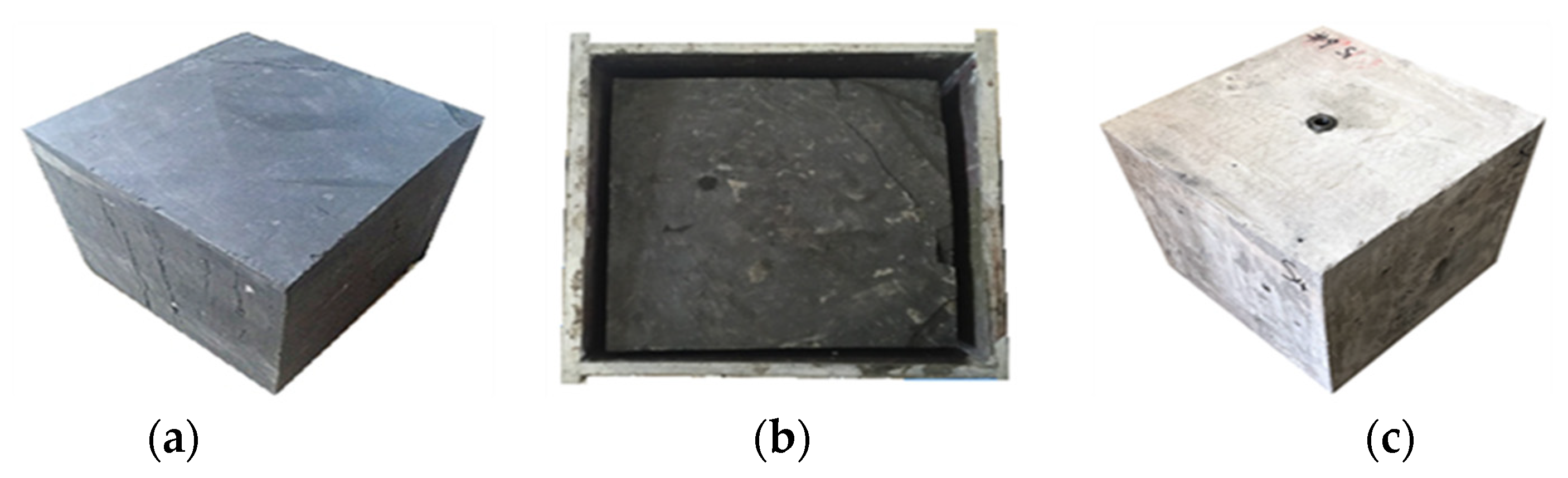
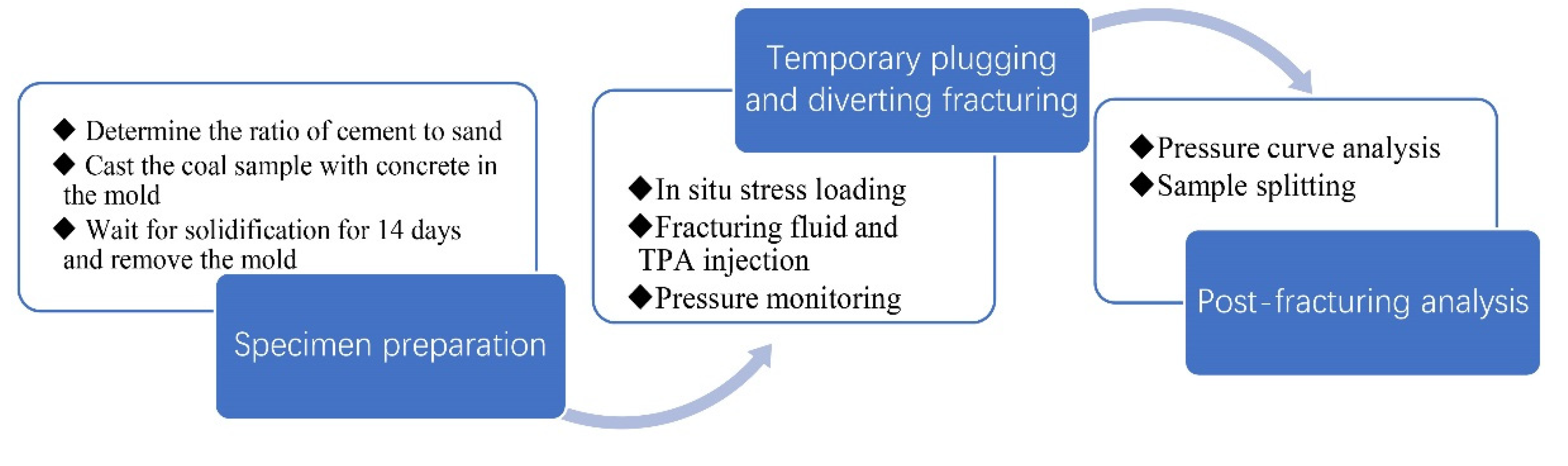
2.1. Specimen Preparation

The coal samples were collected from Qinshui Basin. Due to the difficulty of sample collection in the field, coal samples that perfectly fit the specimen chamber of a hydraulic fracturing system can rarely be obtained. Therefore, a concrete casting method was adopted to process irregular coal samples into standard cubes of 300 mm × 300 mm × 300 mm. The mechanical strength of concrete that was used for casting coal sample was optimized by adjusting the ratio of cement to sand, so that the solidified wrapped concrete had similar mechanical strength to that of coal seam. The optimized ratio of cement to sand was 1:7 through a series of tests. The specific processes of the concrete casting method were as follows: (1) Prepare an appropriate amount of cement slurry according to the optimized ratio of cement to sand, mix thoroughly, and pour into the mold; (2) slowly put the coal sample into the mold to ensure that the sample is not inclined and located in the center of the whole mold; (3) continue to pour cement slurry slowly into the mold until full; (4) allow the coal sample to be cured at room temperature for more than 14 days, and then the mold should be removed.
In order to carry out the laboratory fracturing simulation experiment, a long drill bit with an outer diameter of 3 cm was used to drill a central blind hole (wellbore) with a depth of 15 cm on the sample surface parallel to the bedding plane. The steel pipe (simulated casing) with an outer diameter of 2 cm and a length of 12 cm was cemented in the blind hole with epoxy. By doing so, an open hole section of 3 cm was left in the bottom of the borehole, where the primary hydraulic fracture would initiate. Coal samples before and after processing are shown in Figure 2.
A series of tests were carried out to understand the physical properties of coal seam, including porosity and permeability test, Brazilian splitting test, and uniaxial compression test. The testing results showed that the porosity of the coal seam varied from 5% to 10% and the permeability varied from 0.0006 mD to 0.023 mD. The average tensile strength was about 2.0 MPa. The uniaxial compressive strength ranged from 33.75 MPa to 39.51 MPa. The Young’s modulus ranged from 4.6 GPa to 5.1 GPa, and the Poisson’s ratio from 0.32 to 0.36.

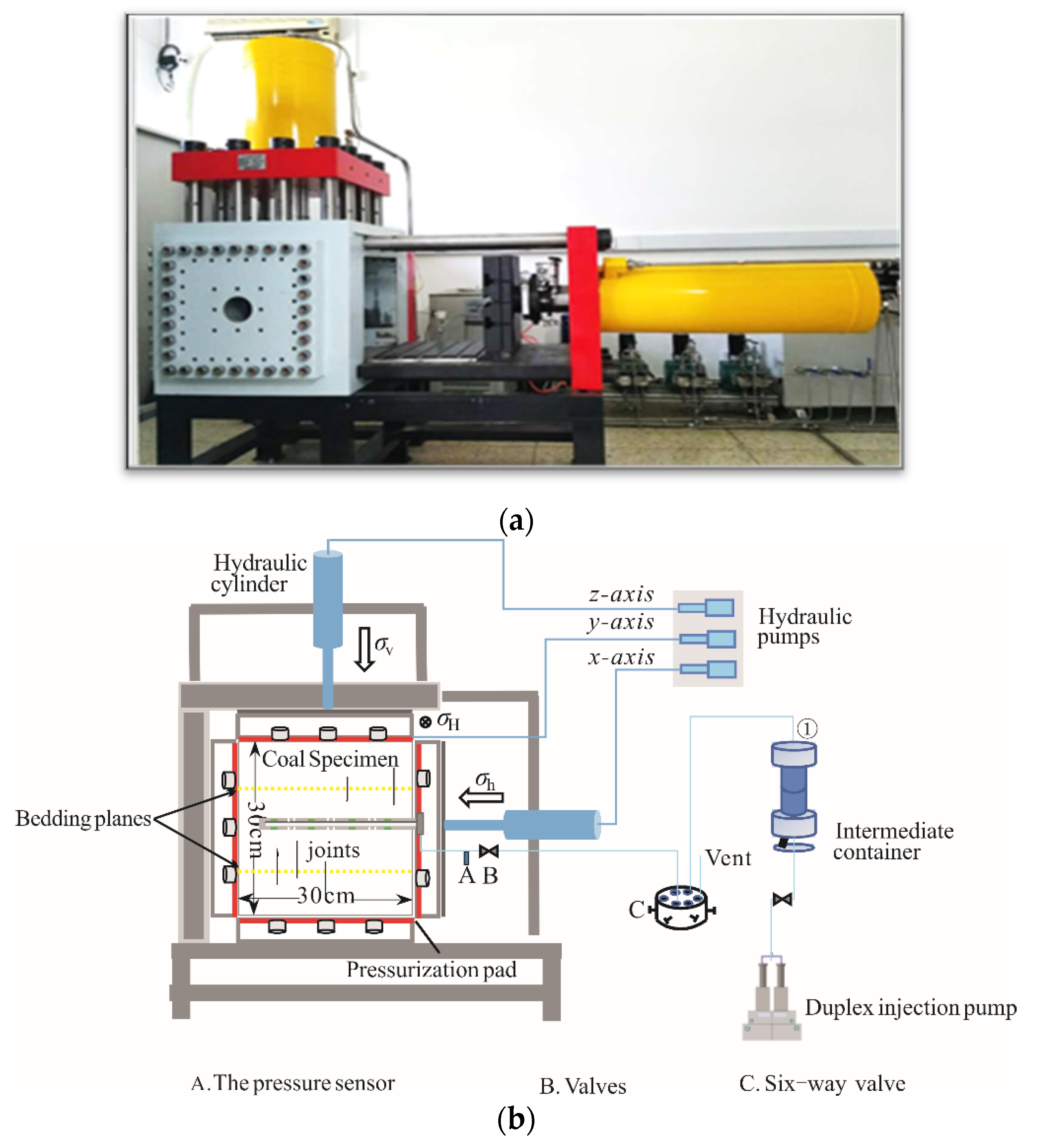
2.2. Experimental Equipment

A set of large-scale true triaxial hydraulic fracturing simulation system (Figure 3) was applied for the fracturing experiment. The coal sample was loaded in the specimen chamber, and three mutually perpendicular stresses were applied to the coal sample to simulate the in situ stress state. The maximum horizontal principal stress and minimum horizontal principal stress were set perpendicular to the wellbore and the vertical stress was parallel to the wellbore direction, so that stress state of a vertical well could be achieved. The fracturing fluid was stored in an intermediate container, where colored dyes were added for identification of hydraulic fracture geometry. The constant speed injection pump was used to pump the fracturing fluid into the wellbore.
In order to make the experimental results reflect the fracturing mechanism, the horizontal stress differences were set according to the actual geological conditions of the coal seam of interest. The size and the concentration of TPA were determined based on field application. The injection rates were selected based on similarity criteria [23]. Experimental parameters are shown in Table 1. The influences of horizontal stress difference, the concentration of TPA, and the particle size of TPA on the hydraulic fracture propagation behavior during TPDF were considered.

2.3. Experimental Procedures

In order to simulate the fracturing process of vertical wells, vertical stress σv was applied along the wellbore, and maximum horizontal principal stress σH and minimum horizontal principal stress σh were applied in the direction perpendicular to the wellbore. In order to avoid the damage of the sample during pressurization, the stress in three directions was simultaneously loaded to σh through the stress loading system; then, the pressure in σh direction was kept constant and the pressure in σH and σv directions were loaded to σH; finally, the confining pressure in σH and σh directions was kept constant, and the pressure in vertical direction was loaded to σv.
In the experiment, low viscosity hydraulic fracturing fluid (slick water with the viscosity of 10 μPa·s) was used in the primary fracturing, which is commonly used in the field. The fracturing fluid for TPDF was hydroxypropyl guar with a viscosity of 45 μPa·s. The fracturing fluid was injected into the wellbore with a constant injection rate of 300 mL/min. A red dye was added in the PF and a blue dye in the TPDF to distinguish the diverted fracture from the primary fracture. Meanwhile, the pressure was monitored in real time. Fluid injection was not stopped until a large amount of fluid was observed on the surface of the sample. The fractured coal sample was depressurized and removed from the sample chamber when injection was stopped. According to the color distribution of the two dyes on the surfaces of the coal sample, the propagation paths of primary fractures and diverted fractures were distinguished, and the three-dimensional fracture spatial distribution was reconstructed. The flow chart of the experiment is shown in Figure 4.

3. Experimental Results and Analysis

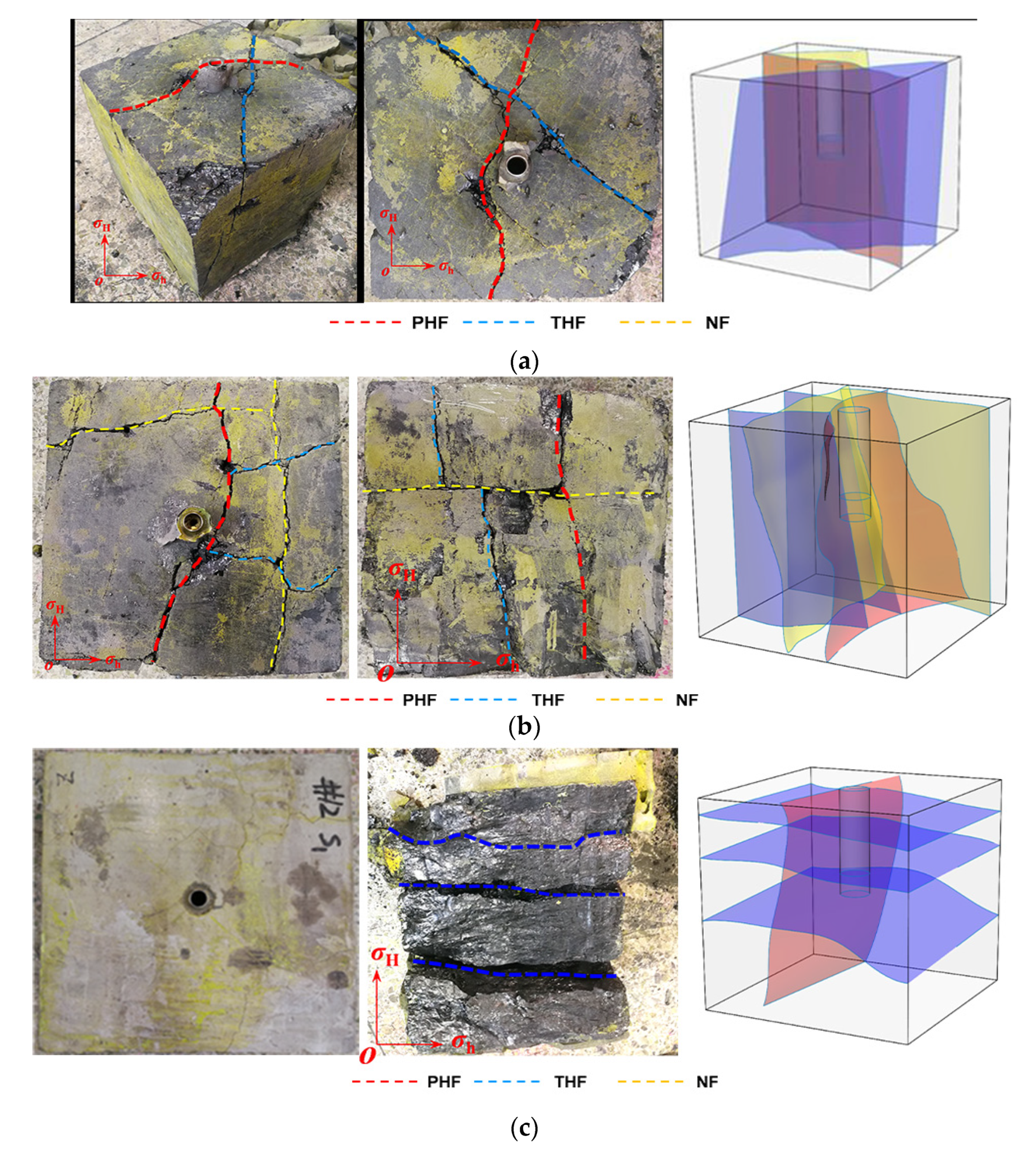
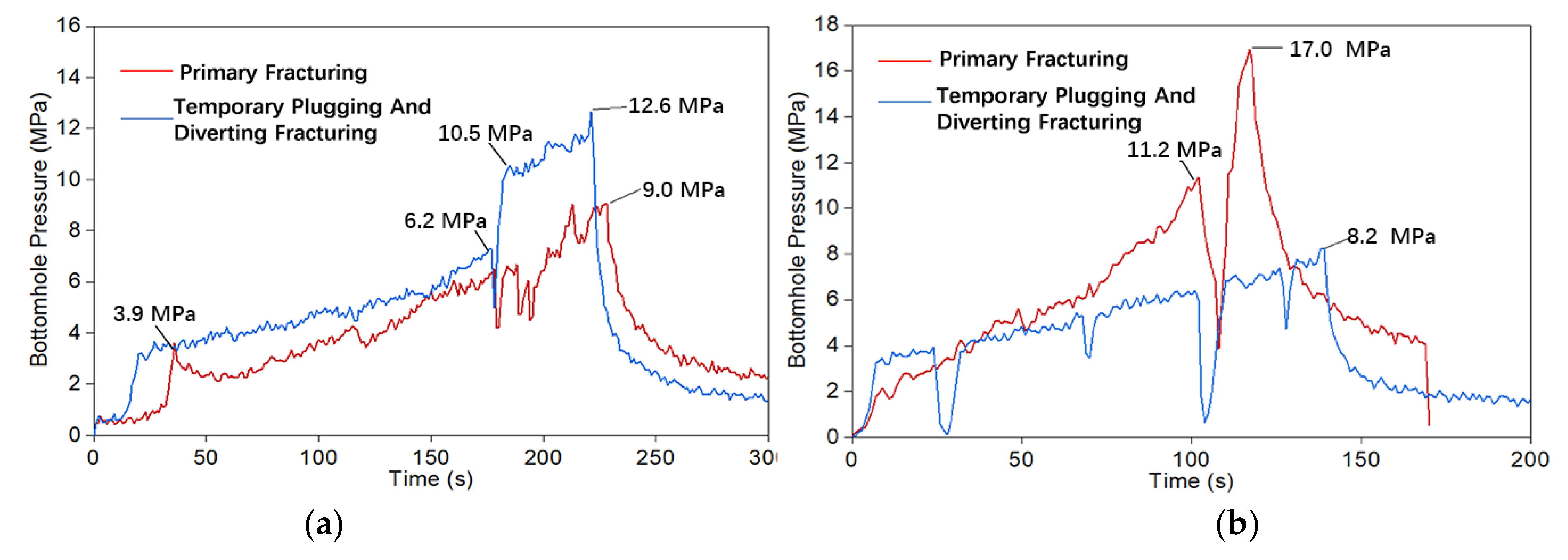
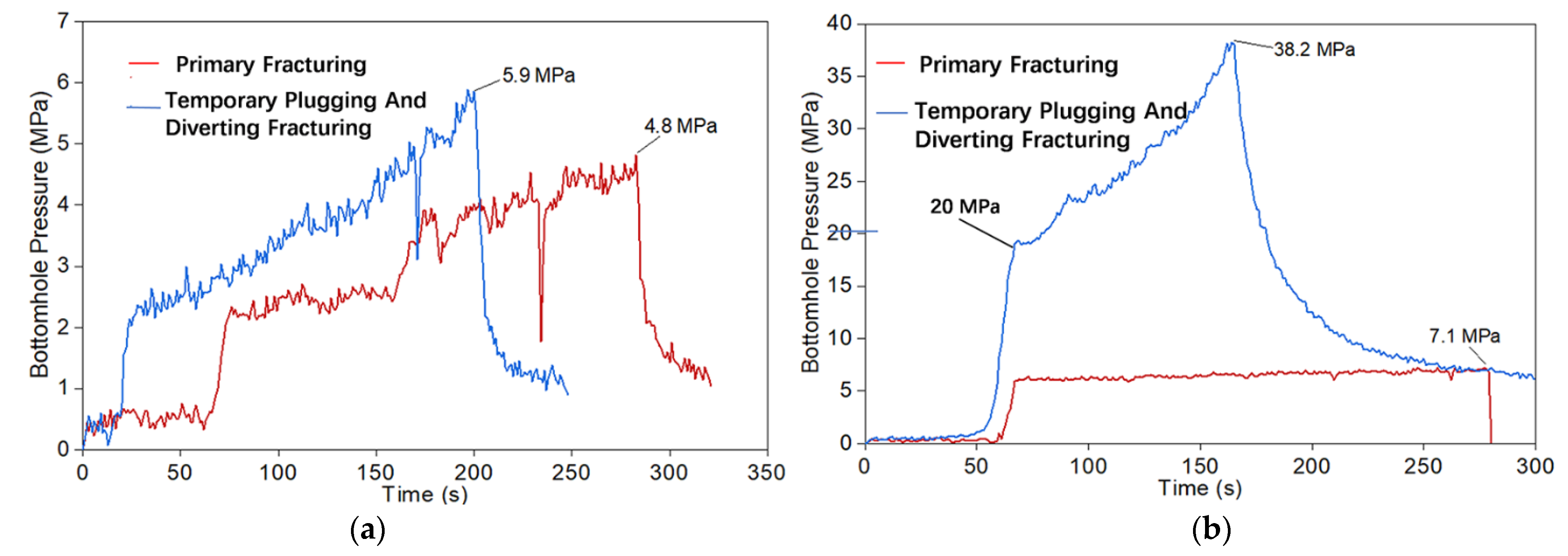
3.1. Effect of Horizontal Stress Difference

Horizontal stress difference is the key factor affecting the hydraulic fracture diverting in coal seam. Studies have shown that low horizontal stress difference facilitates complex fracture formation [24]. To study the spatial relationship of fractures between PF and TPDF under different horizontal stress difference, the horizontal stress difference was set as 2, 4, and 8 MPa. The fracture geometry and pressure curves under different horizontal stress differences were shown in Figure 5 and Figure 6.
As shown by the red marks in Figure 5a, when the horizontal stress difference was 2 MPa, a vertical fracture propagating along the direction of the maximum horizontal principal stress was formed in coal sample 1#, and the deflection of the fracture along the sample surface could be seen locally. The pressure rose slowly at the beginning of the PF, indicating that the natural fractures (NFs) were relatively developed (Figure 6a). When it increased to 3.9 MPa, the pressure decreased slightly, indicating that the micro fractures were locally opened. With the continuous injection of fracturing fluid, the fracture deflected along the joints, leading to the fluctuation of the pressure curve. The breakdown pressure of coal sample 1# was 9 MPa in the PF, resulting in a main fracture propagating along the direction of maximum horizontal principal stress; and the pressure dropped rapidly after reaching the breakdown pressure.
The temporary plugging fracturing experiment was carried out with a concentration of 40 g/L and injection rate of 300 mL/min, as shown by the blue curve in Figure 6a. The hydraulic fracture formed by temporary plugging (THF) intersected the primary hydraulic fracture (PHF) at an angle of about 75°, and the coal fell off locally at the intersection. As can be seen from the pressure curve in Figure 6a, due to filtration of the fracturing fluid, the pressure increased to 6.2 MPa slowly. The THF was not effectively plugged until the slope of the pressure curve increased sharply. When the pressure reached 10.5 MPa, the PHF imitated, but it did not extend to the sample surface until a sudden pressure decline occurred when the pressure reached 12.6 MPa. Moreover, the breakdown pressure of TPDF was 3.6 MPa higher than that of the PF.
As could be seen from Figure 5b, under the condition that the horizontal stress difference was 4 MPa, the PHF of coal sample 2# propagated along the direction of maximum horizontal principal stress. The PHF encountered a NF and opened it partially, and finally crossed the NF and propagated along the original direction, which corresponds to two peaks of the pressure curve in Figure 6b (red line). When the pressure reached 11.2 MPa, a NF in sample 2# was activated partially. Under the action of maximum horizontal stress, the NF was not fully opened and the pressure continued building. When the pressure reached 17 MPa, a PHF was generated and the coal sample completely broke. Several pressure drops were observed during TPDF, but the maximum pressure during TPDF, 8.2 MPa, was smaller than that of PF. This could be explained by the THFs formed during TPDF. Since all THFs were activated joints, which showed low tensile strength, after TPA was pumped, the fluid could be diverted to those joints and activated them with relatively low breakdown pressure. The fracture morphology was complex due to the existence of NFs and the activated joints.
The horizontal stress difference of coal sample 3# was 8 MPa, and the vertical stress was basically equal to the maximum horizontal principal stress. As could be seen from Figure 5c, one vertical fracture along the direction of maximum horizontal principal stress was formed in PF. However, three horizontal fractures were formed after temporary plugging fracturing due to the development of coal bedding planes and the small difference between vertical stress and maximum horizontal principal stress. As shown in Figure 6c, the pressure curve of PF was relatively flat due to the existence of bedding planes and joints in the coal sample 3#. The breakdown pressure in the PF was 14 MPa, and the breakdown pressure in the temporary plugging fracturing was 19.3 MPa, indicating that the primary fracture was effectively plugged. The THFs were activated bedding planes.
Through the comparison of the fracture morphologies of samples 1#–3#, it could be seen that the THFs changed from vertical fractures to horizontal fractures (activated bedding plans) with the increase of horizontal stress difference. Under low horizontal stress difference, THF can initiate in random direction with regard to the PHF, as the induced stress by plugging effect can easily overcome the stress difference. This explains why the THF propagated along the direction of maximum horizontal stress. When horizontal stress was set as 8 MPa, the difference between maximum horizontal stress and vertical stress was only 1 MPa. Under such conditions, the vertical stress can no longer restrain the bedding plane opening. This could account for the activation of bedding planes in sample 3#. The influence of horizontal stress difference for PF and TPDF are different. Horizontal stress difference mainly affects the complexity of the fracture geometry in PF, whereas it mainly determines the fracture orientation of the THF in TPDF.

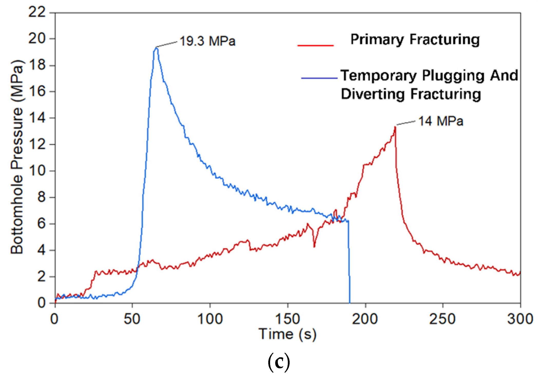
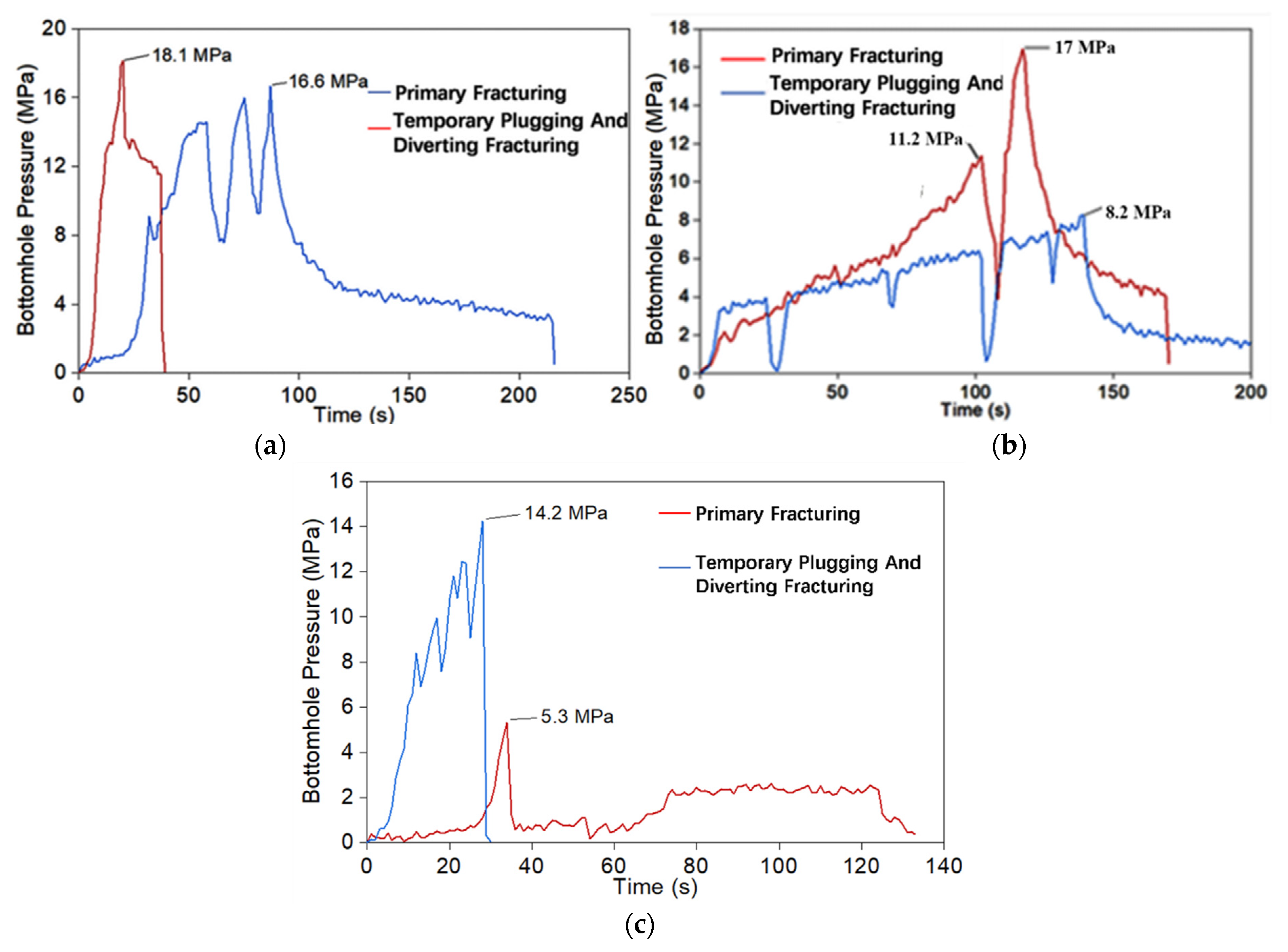
3.2. Effect of the Concentration of TPA

The concentration of TPA is a critical parameter which has a great impact on the effectiveness of TPDF [25,26]. Figure 7 and Figure 8 show the fracture geometries and the injection pressure curves of samples 4# and 5# under different concentrations of TPA. In these two cases, the horizontal stress difference was set to be 4 MPa and the particle size of temporary TPA was 40/70 mesh.
As shown in Figure 8a, the injection pressure of sample 4# slowly increased, which may be attributed to the existence of high-permeability joints near the wellbore. When the injection pressure increased to 4.8 MPa, a PF propagating along the direction of the maximum horizontal stress was created as shown in Figure 7a. During TPDF, TPA with the concentration of 20 g/L was injected. According to the injection pressure curve in Figure 8a, the injection pressure from 25 s to 200 s increased with a slope which was steeper than that of PF linearly, indicating that the TPA reduced the fluid leak-off to certain extent. The breakdown pressure of TPDF was 5.9 MPa, which was only 1.1 MPa higher than that of PF. According to the results of sample splitting (Figure 7a), a new fracture was generated in TPDF, which initially initiated perpendicular to the primary fracture and then diverted to the direction parallel to the primary fracture. By comparing Figure 5b and Figure 7a, it was found that after TPDF, the fracture geometry was simpler and the diversion distance was smaller in sample #4 than those in sample 2#, indicating that the temporary plugging effectiveness was improved by increasing concentration of TPA. It was also proven by the significant increase in the breakdown pressure during the TPDF.
For coal sample #5, the concentration of temporary TPA was 60 g/L. As shown in Figure 8b, during the PF, the injection pressure increased to 7 MPa and then remained stable, indicating that the fluid leak-off dominated. The injection was stopped at the injection time of 275 s without obvious breakdown occurring. After the injection of TPA, the injection pressure increased sharply and the coal sample #5 broke at the breakdown pressure of 38.2 MPa. According to the results of fracture geometry in Figure 7b, after the TPDF, the complexity of hydraulic fracture significantly increased. Multiple PHFs were created and radially propagated outward.
Under the low TPA concentration of 60 g/L, effective plugging could not be achieved, since there was not enough TPA to form a plugging zone. Under the high concentration of 60 g/L, the temporary TPA tended to be detained in the wellbore. Consequently, abnormally high breakdown pressure was induced, which was beneficial for the hydraulic fracture to overcome the containment of stress state. However, the accumulation and block of TPA in the wellbore may cause the failure of hydraulic fracturing treatment. Thus, the concentration of TPA should be optimized so that, on the one hand, a dense and firm plugging zone can form; on the other hand, accumulation and block of TPA in the wellbore can be avoided.

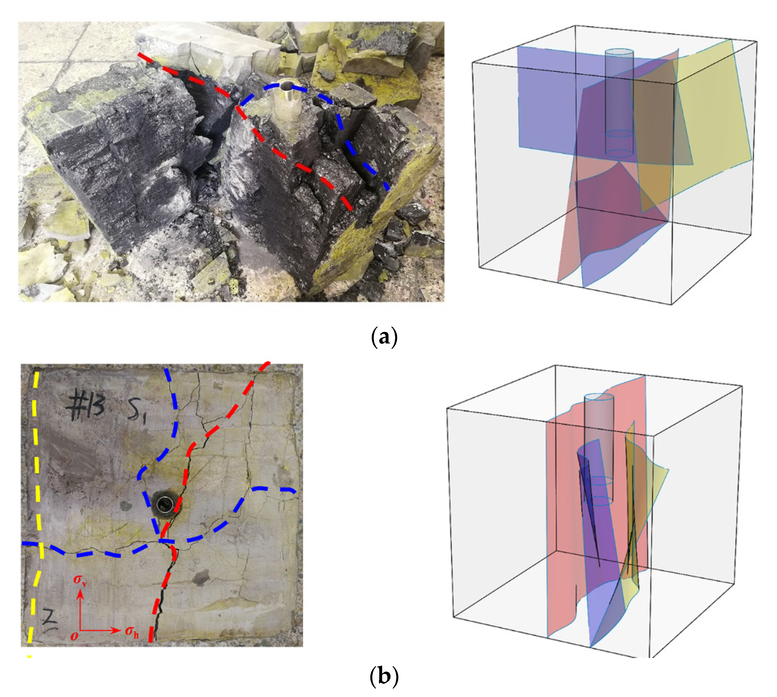
3.3. Effect of the Particle Size of TPA

To analyze the influence of TPA particle size on temporary plugging and diverting fracturing, 20/40 mesh (large particle size), 40/70 mesh (medium particle size), and 80/120 mesh (small particle size) TPAs were selected to carry out fracturing simulation experiments. Figure 9 showed the fracture geometry under different TPA particle sizes obtained through coal sample splitting and fracture reconstruction [27].
As shown in Figure 9, under the condition of horizontal stress difference of 4 MPa and the injection rate of 300 mL/min, vertical fractures along the wellbore were formed in all three coal samples in the PF. The propagation direction of the primary fracture was mainly controlled by stress state, and the overall fracture geometry was relatively simple. When 20/40 mesh was used as temporary TPA, the fracture in sample 6# was still initiated and propagated outward along the primary fracture, and only one new branch fracture was generated far away from the wellbore (Figure 9a). As can be seen from Figure 10a, the breakdown pressure of PF was 16.6 MPa. The fracture propagated perpendicular to the direction of minimum horizontal principal stress and opened the natural weak plane. When reaching the breakdown pressure, a plateau stage of high pressure was observed, indicating that the fracture width was narrow. When temporary TPA of the 20/40 mesh was used, it accumulated in the wellbore due to its large particle size, leading to effective pressure building. The breakdown pressure was 18.1 MPa, which was higher than that of PF.
The particle size of the TPA for sample 2# was 40/70 mesh, which was conducive to being carried into the primary fracture by the fracturing fluid. At the same time, due to the decrease of sand-carrying capacity caused by fracturing fluid filtration and the tortuosity of fracture surface, the temporary TPA gradually settled and bridged in the PHF. With the gradual increase of fluid pressure, two fractures perpendicular to the primary fracture were formed in sample 2# during TPDF (Figure 9b). One of the fractures initiated from the primary fracture and propagated to the boundary of the sample after directly penetrating through the NF. The other fracture initiated from the open hole section and diverted along the NF when encountering the NF, then continued to propagate to the boundary.
Since the fracturing fluid had better ability to suspend TPA of small size, it was easier for small-size TPA to enter the fracture and migrate away from the wellbore. When TPA of smaller particle size (80/120) was used, it distributed in the whole fracture surface of PF (Figure 9c). However, since the effective plugging in the primary fracture was not formed, the pressure in the temporary plugging fracturing was relatively low, only the bottom bedding plane, which communicated with the primary fracture, was partially opened in the rock sample. As shown in Figure 10c, the breakdown pressure of sample 7# in the PF was 5.3 MPa, and a vertical fracture parallel to the horizontal maximum principal stress was formed. A horizontal fracture was formed at the breakdown pressure of 14.2 MPa. Though wide distribution of temporary TPA along the primary fracture surface was observed, the plugging effect was poor and the effective pressure building was small.
By comprehensively comparing the experimental results of samples 2#, 6#, and 7#, the relationship between the particle size of TPA and the fracture width of PF should be considered in the optimization for TPDF. Only when the TPA forms effective plugging in the primary fracture could it ensure the generation of THFs. Improper selection of particle size of TPA would lead to poor temporary plugging effect. The TPA of a large particle size (20–40 mesh) would affect the sand-suspension effect of fracturing fluid, causing the TPA to accumulate in the wellbore and resulting in abnormal treatment pressure. The TPA of small size prevents the formation of effective plugging. In this case, the fracture mainly propagates along the PHF during temporary fracturing. A TPA of 40/70 mesh is relatively reasonable because it could form effective plugging in the primary fracture and promote the generation of THFs.

4. Conclusions

The propagation behavior of hydraulic fracture during TPDF was investigated through laboratory fracturing experiments. The conclusions are as follows:
(1)
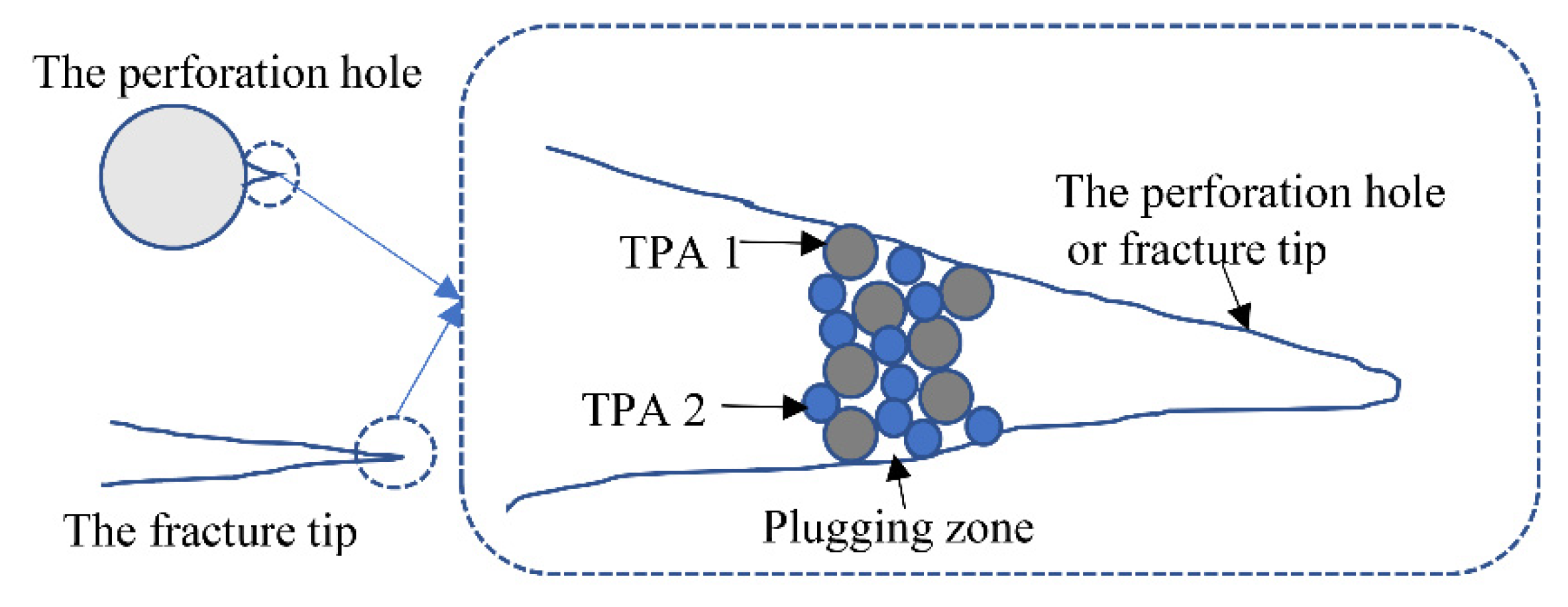
Temporary plugging and diverting fracturing is an effective technique to increase the complexity of hydraulic fracture in coal seam. In this study, the hydraulic fracture generated during the PF tended to propagate along direction of the maximum horizontal stress under different stress states. The injection of TPA can significantly promote the generation of THFs.
(2)
When the particle size of TPA was 20/40 mesh, blockage in the wellbore tended to occur; when the particle size of TPA was 70/100 mesh, the TPA was widely distributed within the primary fracture, which failed to form effective plugging and consequently restricted the generation of THFs. Reasonable particle size (40/70 mesh) of TPA can ensure the entry of TPA into the primary fracture and form effective plugging, which is conducive to the generation of THFs.
(3)
With the concentration of TPA increasing from 20 g/L to 60 g/L, the plugging effectiveness was significantly enhanced. Both the diverting distance and the complexity of hydraulic fractures increased. However, under the high concentration of 60 g/L, the TPA tended to accumulate and block in the wellbore, resulting in an abnormally high breakdown pressure. On one hand, this abnormally high breakdown pressure could overcome the containment of stress state in fracture propagation path. On the other hand, it may cause the failure of hydraulic fracturing treatment.

Author Contributions

Conceptualization, Y.Z.; investigation, B.G. and Q.M.; methodology, Y.Z.; project administration, Y.Z.; visualization, B.G.; writing—original draft, Q.M.; writing—review and editing, B.G. All authors have read and agreed to the published version of the manuscript.

Funding

This research received no external funding.

Institutional Review Board Statement

Not applicable.

Informed Consent Statement

Not applicable.

Data Availability Statement

Not applicable.

Conflicts of Interest

The authors declare no conflict of interest.

References

  1. Huang, S.; Liu, W.; Zhao, G. Current status and development trend of China’s CBM development and utilization. J. China Coal Soc. 2009, 35, 5–10. [Google Scholar]
  2. Shan, X.; Zhang, S.; Li, A. Analysis of fracture propagation law of coalbed methane wells. Nat. Gas Ind. 2005, 1, 161–163. [Google Scholar]
  3. Cao, X.; Zhu, Y.; Wang, D. Occurrence characteristics and gas-controlling geological factors of coalbed methane in Zhengzhuang block. Coal Geol. Prospect. 2011, 39, 16–42. [Google Scholar]
  4. Zhao, X.; Zhu, Q.; Sun, F. Practice and thinking on exploration and development of high-rank coalbed methane in Qinshui Basin. J. China Coal Soc. 2015, 40, 2131–2136. [Google Scholar]
  5. Zhao, X.; Yang, Y.; Sun, F. High-rank coalbed methane accumulation rules and exploration and development technologies in the southern Qinshui Basin. Pet. Explor. Dev. 2016, 43, 303–309. [Google Scholar] [CrossRef]
  6. Gomaa, A.M.; Nino-Penaloza, A.; Castillo, D.; McCartney, E.; Mayor, J. Experimental Investigation of Particulate Diverter Used to Enhance Fracture Complexity. In Proceedings of the SPE International Conference and Exhibition on Formation Damage Control, Lafayette, LA, USA, 24–26 February 2016. SPE-178983-MS. [Google Scholar]
  7. Rassenfoss, S. Getting more from fracturing with diversion. J. Pet. Technol. 2017, 69, 42–47. [Google Scholar] [CrossRef]
  8. Bell, G.J.; Jones, A.H. Coal seam hydraulic fracture propagation on a laboratory scale. In Proceedings of the 1989 Coal-Bed Methane Symposium, Tuscaloosa, AL, USA, 17–20 April 1989; Volume 8994, pp. 17–20. [Google Scholar]
  9. Abass, H.H. Experimental observations of hydraulic fracture propagation through coal blocks. In Proceedings of the SPE Eastern Regional Meeting, Columbus, OH, USA, 31 October–2 November 1990. [Google Scholar]
  10. Deng, G.; Wang, S.; Huang, B. Study on the behavior of hydraulic crack propagation in coal and coal. Chin. J. Coal Mech. Eng. 2004, 23, 3489–3493. [Google Scholar]
  11. Du, C. The Theory and Application of Coal Seam Hydraulic Fracturing. Ph.D. Thesis, China University of Mining and Technology, Beijing, China, 2008. [Google Scholar]
  12. Yang, J.; Wang, Y.; Li, A. Experimental study on the law of coal and coal hydraulic crack propagation. J. China Coal Soc. 2012, 37, 73–77. [Google Scholar]
  13. Zou, Y. Simulation of Hydraulic Fracture Propagation in Coal Seams. Ph.D. Thesis, China University of Petroleum, Beijing, China, 2011. [Google Scholar]
  14. Cheng, Y.; Xu, T.; Wu, B. Experimental study on fracture morphology of coal and coal hydraulic fracturing. Nat. Gas Geosci. 2013, 24, 134–137. [Google Scholar]
  15. Zhang, Y.; Zhang, S.; Liu, Y. Experimental study on crack propagation law of coal and coal hydraulic fracturing. China Coal Geol. 2015, 27, 21–25. [Google Scholar]
  16. Huang, G.; Liu, W.; Wang, X. Application of Fracture Turning Fracturing Technology in Xinjiang Oilfield. Xinjiang Pet. Sci. Technol. 2008, 3, 21–24. [Google Scholar]
  17. Dai, J.; Zhong, S.; Xiong, J. Research and application of temporary plugging and fracturing technology in Pingbei Oilfield. Drill. Prod. Technol. 2006, 29, 67–69. [Google Scholar]
  18. Wu, Y.; Chen, F.; Cheng, N. Using manual temporary plugging and steering to improve the effect of repeated fracturing. Drill. Prod. Technol. 2008, 31, 59–61. [Google Scholar]
  19. He, C.M.; Shi, S.Z.; Zhong, K.W.; Chen, J.; Jiang, W.; Cheng, N. Performance Evaluation of Water Soluble Diverter Agent and its Temporary Plugging Effect in Refracturing. In Proceedings of the IOP Conference Series: Earth and Environmental Science, Xiamen, China, 1–3 March 2018; Volume 188, p. 012071. [Google Scholar]
  20. Liu, S.; Guo, T.; Rui, Z.; Ling, K. Performance Evaluation of Degradable Temporary TPA in Laboratory Experiment. J. Energy Resour. Technol. 2020, 142, 123002. [Google Scholar] [CrossRef]
  21. Ma, X.; Zou, Y.; Li, N.; Chen, M.; Zhang, Y.; Liu, Z. Experimental study on the mechanism of hydraulic fracture growth in a glutenite reservoir. J. Struct. Geol. 2017, 97, 37–47. [Google Scholar] [CrossRef]
  22. Zou, Y.; Gao, B.; Zhang, S.; Ma, X.; Sun, Z.; Wang, F.; Liu, C. Multi-fracture nonuniform initiation and vertical propagation behavior in thin interbedded tight sandstone: An experimental study. J. Petrol. Sci. Eng. 2022, 213, 110417. [Google Scholar] [CrossRef]
  23. Liu, G.H.; Pang, F.; Chen, Z.X. Similarity criterion in hydraulic fracturing simulation experiments. J. Univ. Pet. 2000, 05, 45–48. [Google Scholar]
  24. Olson, J.E.; Taleghani, A.D. Modeling simultaneous growth of multiple hydraulic fractures and their interaction with natural fractures. In Proceedings of the SPE Hydraulic Fracturing Technology Conference, The Woodlands, TX, USA, 19 January 2009. SPE 119739. [Google Scholar]
  25. Wang, Y.; Yuan, L.; Ren, J. Research and application progress of temporary plugging agents for steering fracturing. Sci. Technol. Eng. 2017, 17, 196–204. [Google Scholar]
  26. Su, L.; Pang, P.; Da, Y. Optimization and field test of TPA dosage for temporary plugging and repeated fracturing in low permeability oilfields. Fault Block Oil Gas Field 2014, 21, 114–117. [Google Scholar]
  27. Li, N.; Zhang, S.; Ma, X. Experimental study on the propagation law of hydraulic fractures in glutenite reservoirs. Chin. J. Coal Mech. Eng. 2017, 36, 2383–2392. [Google Scholar]
Figure 1. Schematic diagram of temporary plugging mechanism.
Processes 10 00731 g001
Figure 2. Coal sample before and after casting: (a) coal sample before casting; (b) the mold; (c) coal sample after casting.
Processes 10 00731 g002
Figure 3. True triaxial hydraulic fracturing simulation system: (a) a picture of true triaxial hydraulic fracturing simulation system [21]; (b) schematic diagram of triaxial hydraulic fracturing simulation system [22].
Processes 10 00731 g003
Figure 4. The flow chart of the TPDF experiment.
Processes 10 00731 g004
Figure 5. Fracture morphology of samples 1#-3# after TPDF: (a) fracture morphology of sample 1#; (b) fracture morphology of sample 2#; (c) fracture morphology of sample 3#.
Processes 10 00731 g005
Figure 6. Pressure curves for coal samples 1#–3#: (a) pressure curves of sample 1#; (b) pressure curves of sample 2#; (c) pressure curves of sample 3#.
Processes 10 00731 g006aProcesses 10 00731 g006b
Figure 7. Effect of the concentration of TPA on THF morphology: (a) fracture morphology of sample 4#; (b) fracture morphology of sample 5#.
Processes 10 00731 g007
Figure 8. Pressure curves for coal samples 4# and 5#: (a) pressure curves of sample 4#; (b) pressure curves of sample 5#.
Processes 10 00731 g008
Figure 9. Effect of the particle size of TPA on fracture geometry: (a) fracture morphology of sample 6#; (b) fracture morphology of sample 2#; (c) fracture morphology of sample 7#.
Processes 10 00731 g009
Figure 10. Pressure curves of coal samples 2#, 6#, and 7#: (a) pressure curves of sample 6#; (b) pressure curves of sample 2#; (c) pressure curves of sample 7#.
Processes 10 00731 g010
Table 1. Experimental scheme.
Specimen Numberσv, σH, σh
(MPa)
Injection Rate
(mL/min)
Concentration
of TPA (g/L)
Size of TPA
(Mesh)
1#12, 7, 5300 + 3004040–70
2#12, 9, 5300 + 3004040–70
3#12, 11, 3300 + 3004040–70
4#12, 9, 5300 + 3002040–70
5#12, 9, 5300 + 3006040–70
6#12, 9, 5300 + 3004020–40
7#12, 9, 5300 + 3004080–120
Publisher’s Note: MDPI stays neutral with regard to jurisdictional claims in published maps and institutional affiliations.

