Abstract
This paper proposes an evaluation system for the sealing ability of cement–casing interface and cement matrix, which was developed based on a permeability testing device and a model that predicts the breakthrough pressure of cement sheath matrix and interfacial transition zone (ITZ). It was found that the breakthrough pressure of ITZ was much smaller than that of cement matrix. Moreover, compared with water-based drilling fluid, oil-based one led to lower breakthrough pressure of ITZ even after the flushing treatment. Meanwhile, latex, resin and elastic materials enabled a substantial rise in the breakthrough pressure of cement matrix. However, compared with the latex, resin and elastic cement, the expansive cement had higher breakthrough pressure of ITZ, indicating an improvement on the interface sealing ability. Additionally, a small enlargement rate of the hole diameter and long effective bond were able to prevent gas storage wells from leakage.
1. Introduction
“To cut greenhouse gas emissions by 80–100% by 2050 or sooner” is the goal of Carbon Neutral Cities Alliance [1] and has promoted the development of the natural-gas industry. As a critical component of the natural-gas supply and distribution chain, underground gas storage (UGS) is playing an increasingly important role in this sector [2]. Maintaining the wellbore sealing integrity of UGS wells is a key issue concerning the safety of the staff, the surrounding environment and the UGS itself [3]. The sealing failure of the cement sheath results in sustained casing pressure (SCP), which is a common phenomenon that raises potential risk concerns [4].
The quality of the resultant annular cement sheath is crucial for sealing integrity [5]. The quality of the cement sheath is evaluated not only by the compressive strength, bond strength, and permeability [6], but also by the sealing ability of the interface of the cement casing and cement formation. Yang, Kuru [7] found that leakage is most likely to occur near the interface, either the one between the cement and casing or the cement and formation. Therefore, interfaces play an essential role in the sealing integrity of the cement sheath. An important component of the cement sheath is the interfacial transition zone (ITZ) between the casing (and formation) and cement [5], which significantly affects the sealing integrity of the cement sheath. In the present study, the sealing ability of the cement–casing interface and cement matrix was investigated.
Numerous methods have been used to assess the interface’s sealing integrity of the cement sheath, mainly including the interface’s bonding strength, gas channeling, scanning electron microscope (SEM), and µ-CT [5,7,8,9]. For instance, Yang [7] employed SEM and µ-CT to investigate the effects of the environmental cement-drying shrinkage and the expansion agent on the sealing ability of the interface. However, the interface’s bonding strength cannot be used to evaluate the leakage capacity of channels such as micro-cracks and large pores. In other words, a high interfacial bonding strength may still accompany serious SCP. The channeling pressure of the gas-channeling test is time dependent and is thus unable to quantitatively represent the sealing ability of the cement sheath. SEM and µ-CT are not suitable for field applications due to the cost, complex operating procedure and strong professionalism required. Underground gas-storage cement is in need of an evaluation system with convenient operation, high applicability and low cost.
Considering its wide and successful application in reservoir caprocks [10], the breakthrough pressure was selected to assess the sealing ability of the cement–casing interface and is generally described by the Laplace law [11]:
where σ is the interfacial tension, N/m; θ is the contact angle, °; and is the radius, m. Breakthrough pressure is a vital parameter for evaluating the effectiveness of the cement sheath on gas sealing. One of the major reasons accounting for SCP is gas leakage due to the differential pressure of the cap rock and cement sheath. High breakthrough pressure of the cement sheath ensures better sealing integrity and lower leakage risk. The porosity of the matrix and the ITZ of the cement sheath is close to that of rock, whose breakthrough pressure can be used to determine the sealing ability of the cement sheath.
In this work, a model was built to predict the breakthrough pressure of the ITZ of the cement–casing interface and cement matrix, based on which a measuring method was presented. The accuracy and reliability of the new evaluation system was verified. The effects of oil- and water-based drilling fluids and flushing fluids on the sealing ability of the cement sheath were also investigated by breakthrough pressure. The system was finally applied to an underground gas-storage well.
2. Interfacial Transition Zone
The ITZ is a typical micro-meso structure with a thickness of 40–100 μm [12,13,14]. The properties of the ITZ differ from that of the cement matrix [15]. The radial micro-cracks, micro-annuli and macro-porosity that develop in the ITZ of the cement–casing interface [5,16,17] result in the permeability reaching 600 mD or even higher [7,18,19], which is higher than that of the cement matrix (usually less than 0.01 mD). Therefore, the ITZ is a potential leakage channel for natural gas in underground gas storage.
The ITZ of the cement sheath has two parts, including the casing–cement interface (first interface) and the formation–cement interface (second interface) (Figure 1). However, the pore structure and permeability are different between the two transition zones [7]. Besides, the cement sheath is a porous media with three permeabilities: the ITZ is highly permeable while the cement matrix is a low-permeability medium. This study investigated the breakthrough pressure of the ITZ of the casing–cement interface and matrix.
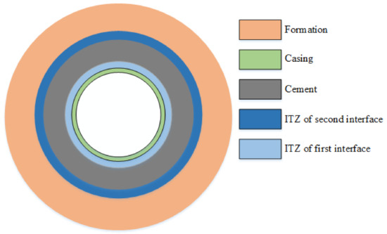
Figure 1.
Schematic diagram of the transition zones in cement sheath.
3. Breakthrough-Pressure-Prediction Model
3.1. Breakthrough Pressure of Matrix
The breakthrough pressure of the cement matrix is higher than that of the ITZ and can be described as follows [20]:
where is the breakthrough pressure, Pa; is the tortuosity, m/m; is the interfacial tension of gas, N/m; θg is the contact angle of gas, °; is the permeability of the cement matrix, m2; is the pore-shape factor, 2; and is the porosity of the cement matrix, %.
The porosity of the cement sheath depends on the water-cement ratio and the hydration degree. The porosity of the cement matrix can be determined by the following equation [21]:
where is the max hydration degree, %. is the water-cement ratio, %.
The hydration degree of a cement slurry mainly depends on the water-cement ratio, curing conditions and time. After the cementing construction of the gas storage, it takes so long to start gas injection that the cement will be fully hydrated. As the specimens had been cured for a long time, the maximum hydration degree of the cement slurry was applied in this model and was calculated by the following equation [22]:
The tortuosity is the geometric feature of the pore structure and is only closely related to the porosity of the cement stone. Koichi, Tetsuya [23] found that the tortuosity of cement stone decreases as the porosity in the cement increases, and its changing is expressed mathematically as:
3.2. Breakthrough Pressure of ITZ
According to the seepage characteristics, the high permeability of the ITZ and the low permeability of the matrix have the following relationship [24]:
where is the radius of the cement sheath, m; h is the thickness of the ITZ, m, which is 7 × 10⁻⁵ in this paper; , , is the permeability of the cement–casing interface, matrix and ITZ, respectively.
When , Equation (6) can be written as:
The porosity and permeability of the ITZ can be calculated by the following equation [25]:
where is the porosity of ITZ; B represents the Raleigh–Ritz pore-size-distribution constant in HYMOSTRUC and is 3.6 × 10⁷ m−1; is the viscosity, Pa·s.
The breakthrough pressure of the ITZ is presented as follows:
4. Model Verification
4.1. Contact Angle
The neat-cement and expansion-cement slurries with a water-cement ratio of 0.44 were used to verify the accuracy of the breakthrough-pressure-prediction model. These cement slurries were cured in water (90 °C, 21 MPa) for seven days. The contact angles of the cements, as indicated in Figure 2, were measured and the averages of the measurements are shown in Table 1. The addition of expansion agents increased the contact angle, suggesting the hydrophobic nature of these agents.
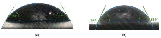
Figure 2.
Contact angles of two cement slurries. (a) neat cement; (b) expansion cement.

Table 1.
Composition of the prepared cement samples.
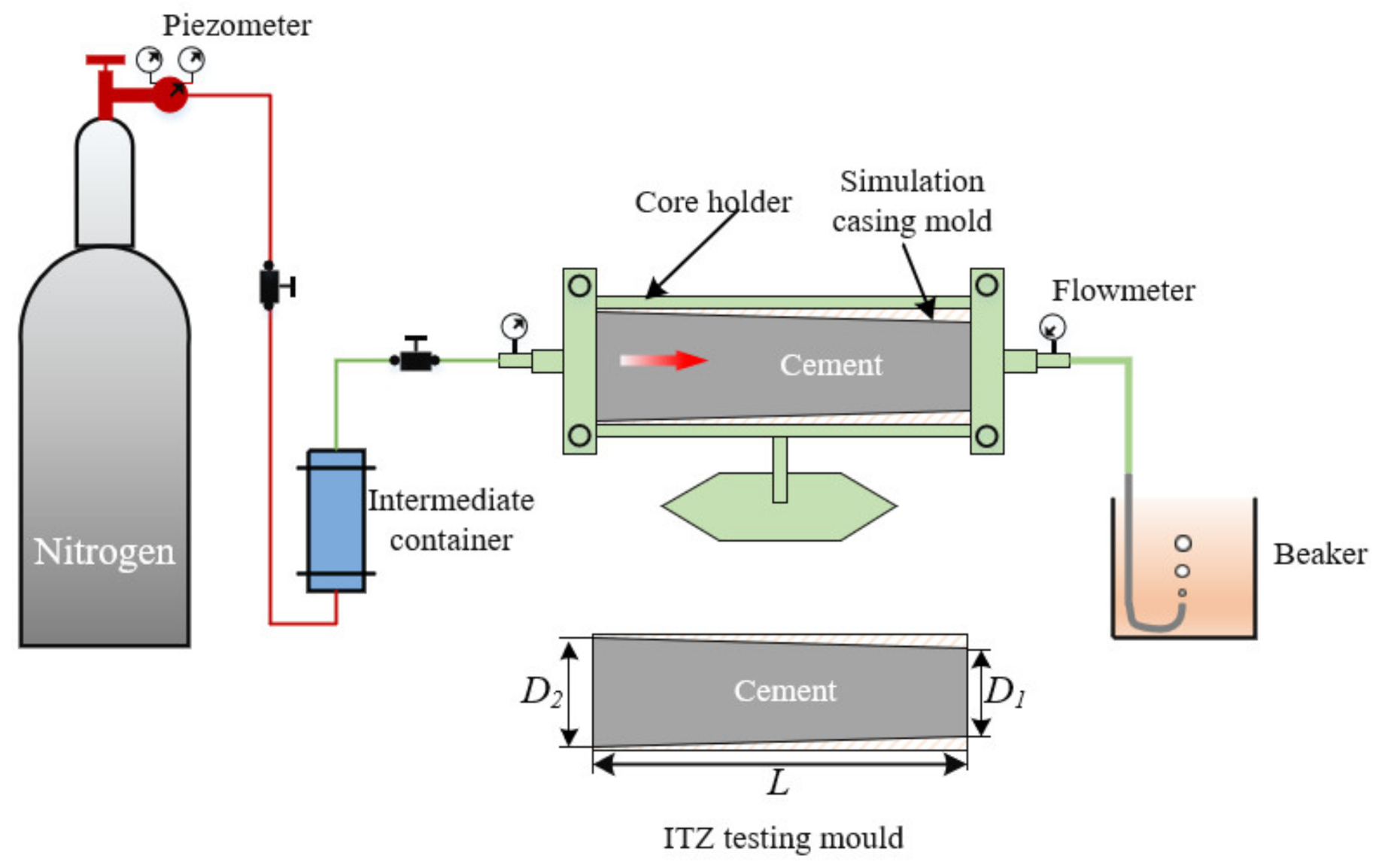
The breakthrough-pressure-testing device is composed of a nitrogen source, intermediate container, core holder, simulation casing mold, cement sheath, and flowmeter, etc. The essential component is the simulation casing mold, which has a certain slope inside with a value satisfying Equation (10). The purpose of this design is to prevent the pressure difference between the two ends of the cement column from exceeding the bonding strength of the cement, which will lead to micro-annuli.
4.2. Verification Method
- Step 1: Measure the gas permeability of the cement matrix by the gas-permeability method.
- Step 2: Use Equation (2) to calculate the breakthrough pressure of the cement matrix ().
- Step 3: Measure the gas permeability of the ITZ and use Equation (7) to calculate the permeability of the ITZ ().
- Step 4: Use Equation (9) to calculate the breakthrough pressure of the ITZ .
- Step 5: Put the cured specimen of the ITZ-testing mold (Figure 3) into the core holder and apply a confining pressure that is double the matrix breakthrough pressure ().
- Step 6: Apply the of the ITZ to the specimen as a test of the pressure difference. If no bubbles appear after waiting for 10 h, then increase the pressure by 0.1 MPa. Repeat this step until bubbles appear and record the pressure difference.
The permeability of the total mold and cement matrix are shown in Table 2 and the verified results are shown in Figure 4. It was found that the errors of the breakthrough pressure of the cement matrix and the ITZ of the neat-cement-slurry system were 3.85% and 4.17%, respectively, and those of the expansive-cement-slurry system were 2.44% and 6.74%, respectively, indicating accurate predictions of the breakthrough pressure of the ITZ by this model. The breakthrough pressure of the ITZ of the expansion cement was 185.4% higher than that of the neat cement. Expansion agents were added to the cement to reduce or avoid the shrinkage during cement-slurry setting, contributing to minimized gap or cracks of the ITZ [7,26]. This means a reduced permeability of the ITZ and the resultant increase in the breakthrough pressure.
Table 2.
Verified results of breakthrough pressure.

Figure 4.
Experimentally verified results of breakthrough pressure of matrix and ITZ.

Figure 3.
Schematic diagram of breakthrough-pressure-testing device.
Figure 3.
Schematic diagram of breakthrough-pressure-testing device.
5. Factors Influencing Breakthrough Pressure
5.1. Drilling Fluid
Since drilling fluid and flushing fluid mainly act on the casing–cement interface, this study only analyzed the breakthrough pressure of the ITZ. To determine the effect of water-based and oil-based drilling fluids on the breakthrough pressure of the casing–cement interface, the steel tubes were immersed in two drilling fluids for 24 h, and then flushed with flushing fluid. The effect of the treatment on the breakthrough pressure of the cement–casing interface was analyzed, and the results are shown in Figure 5. Compared with the oil-based drilling fluid, the water-based fluid led to a much higher breakthrough pressure of the treated steel tube, which was further augmented by the flushing-liquid treatment. The oil-based-drilling-fluid treatment left an oil film on the surface of the steel tube, which could not be completely removed by the flushing-fluid treatment. The oil film changed the hydrophilicity of the surface of the casing: the contact angles of the steel treated by oil-based and water-based drilling fluid were 86.5° and 68.1°, respectively, which were reduced to 65.6° and 53.3° by flushing. According to Equation (10), the degree of the contact angle negatively correlates with the breakthrough pressure.
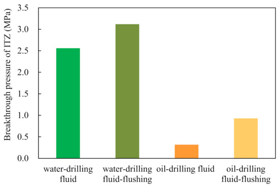
Figure 5.
Impact of drilling fluids on the breakthrough pressure of ITZ. Drilling fluid and flushing fluid are from the construction site.
5.2. Cement Slurries
The breakthrough pressure of the matrix and the ITZ of the expansive-cement, elastic-cement, latex-cement and resin-cement slurries were analyzed and the results are shown in Figure 6 and Figure 7. The different types of cement ranked in descending order of the breakthrough pressure of the matrix are as follows: latex cement, resin cement, expansive cement, elastic cement and neat cement, with the pressure of the first two types much higher than that of the rest. First of all, latex and resin have a film-forming effect, which can greatly reduce the permeability of the cement matrix [27,28]. Additionally, latex and resin change the hydrophilicity of the cement and increase the contact angle, which raises the matrix breakthrough pressure. In descending order of the breakthrough pressure of the ITZ are expansive cement, latex cement, resin cement, elastic cement, and neat cement (Figure 7). Expansion agents reduce the micro-gap caused by cement shrinkage, and latex and resin improve the bonding effect of the interface, both of which cause a dramatic increase in the breakthrough pressure of the ITZ. The breakthrough pressures of elastic cement, latex cement and expansive cement were 17.7%, 64.5% and 85.4%, respectively, which were higher than that of the neat slurry. Compared with swellable materials and latex, elastic materials have less influence on the breakthrough pressure. Figure 7 shows that the breakthrough pressure of the matrix remained constantly high while the breakthrough pressure of the ITZ varied. The expansion material had a better effect than latex and resin on increasing the breakthrough pressure of the ITZ.
Figure 6.
Impact of cement slurries on the breakthrough pressure of matrix.
Figure 7.
Impact of cement slurries on the breakthrough pressure of ITZ.
6. Application
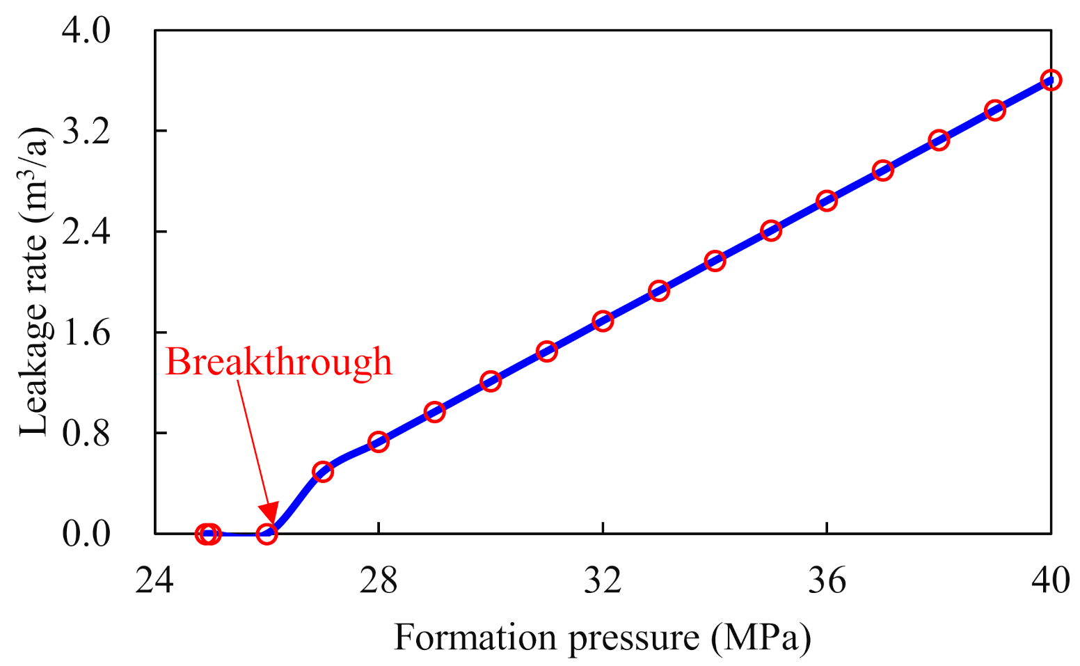
We applied the evaluation system to an underground gas-storage well in Sichuan Basin, the basic information of which is shown in Table 3. The expansive elastic-cement slurry was used for cementing the gas-storage well, and its performance is shown in Table 4. The leakage rate of the ITZ was predicted by Equation (11). The result in Figure 8 shows that the breakthrough pressure is negatively correlated with the leakage rate.
where is the formation pressure, MPa; is the density of the formation water, kg/m3; g is the gravity acceleration, m/s2; H is the depth of the top of caprock, m; is the radius of the casing, m; is the thickness of the caprock, m.
Table 3.
Basic information of an underground gas storage.
Table 4.
Performance parameter of expansive-elastic cement.
Figure 8.
The relationship between leakage rate and formation pressure.
When gas was first injected, the formation-pore pressure was too low to leak (Figure 8). However, the pore pressure continued rising with the continuous injection of natural gas into the formation. When the pore pressure of the formation reached 27.0 MPa, the difference between the pore pressure and hydrostatic column one (2.1 MPa) exceeded the breakthrough pressure (1.8 MPa) of the ITZ, resulting in leakage. When the pressure difference was only slightly higher than the breakthrough pressure of the cement matrix (4.85 MPa), the increase in the leakage rate was not significant, because the contribution of the matrix to the rate is extremely low. When the pore pressure increased to 40.0 MPa, the leakage rate of the matrix was only 0.006 m3/a. When the pressure difference outran the breakthrough pressure, the leakage rate rose linearly with the increase in pore pressure. When the pore pressure increased by 33.3% from 30.0 to 40.0 MPa, the leakage rate climbed by 197.1%.
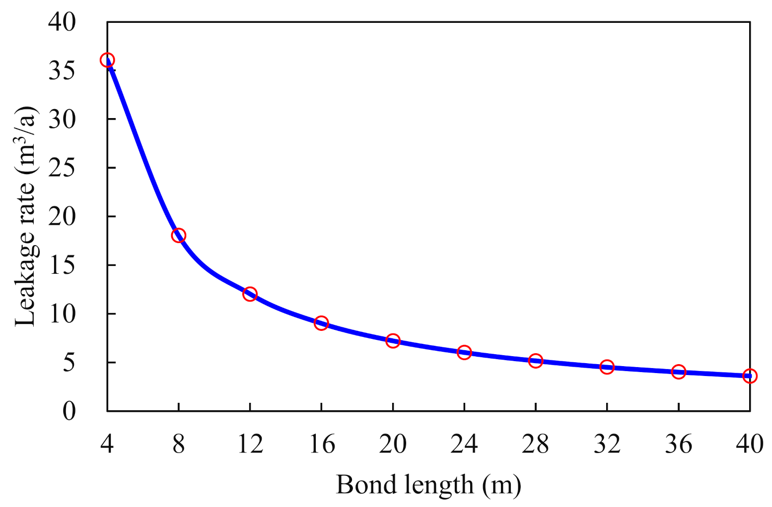
With poor cementing quality, the effective bonding length of the cement–casing-interface sheath greatly impacted the leakage rate, as shown in Figure 9. As the effective bonding length increased, the drop in the leakage rate was initially dramatic and then gradually slowed down. The leakage rate dropped by 400.0% as the effective bonding length increased from 4 m to 20 m, but only reduced by 66.5% when the length rose from 24 m to 40 m. The cement sheath with such performance ensured that significant leakage could be avoided by an effective bond between the cement–casing interface longer than 24 m.
Figure 9.
The influence of the effective bonding length of cement sheath on the leakage rate.
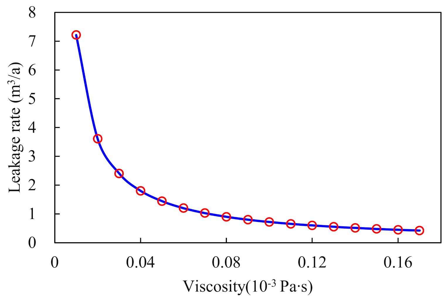
As the viscosity of fluid in the formation increased, the leakage rate decreased rapidly and then gradually slowed down (Figure 10). Viscosity had a comparable effect on the leakage rate as bonding length. Viscosity negatively correlated with the leakage rate, which reduced from 7.2 to 0.9 m3/a as the viscosity was increased from 0.01 to 0.08 mPa·s. Natural gas contains more impurities under formation conditions [29]. The heterogeneity of the gas caused high viscosity, which decelerated the leakage.
Figure 10.
The effect of the viscosity of formation fluids on the leakage rate.
The borehole diameter positively correlated with the leakage rate (Figure 11). An increase in the borehole diameter raised the contact area between the cement sheath and the casing, as well as the ITZ. When the diameter of the drill bit was constant, a larger diameter of the wellbore led to a greater expansion rate, which increased by 88% as the hole diameter was enlarged by 14%. The expansion rate of the borehole should be controlled during the drilling.
Figure 11.
The wellbore diameter effect on the leakage rate.
7. Conclusions
In the present study, an evaluation system used the breakthrough-pressure model to determine the sealing ability of the cement–casing interface and cement matrix in underground gas-storage wells. The quantitative evaluation generated by this system allows the rational selection of flushing fluids and cement slurries. We employed the system to evaluate the effect of the drilling fluid, flushing fluid, and sealing ability of the cement slurries on breakthrough pressure, and an analysis of the leakage of the cement–casing-interface was performed in an underground gas-storage well. The following are the obtained results:
- Compared with water-based drilling fluid, oil-based fluid decreased the breakthrough pressure of the ITZ by changing the contact angle. The pressure could be increased by fluid flushing.
- The breakthrough pressure of the matrix of latex and resin cement was higher than that of expansive cement, whereas the breakthrough pressure of the ITZ of latex and resin was lower than that of expansive cement. Expansive cement had a better performance in interface sealing.
- The ITZ had a dominant role in the leakage of the cement–casing interface. Continuous injection of natural gas increased the pore pressure of the formation, leading to an increase of leakage in the cement–casing-interface sheath.
- A longer effective bonding length, higher gas viscosity and smaller enlargement rate of the hole diameter led to a smaller leakage rate of the cement sheath-casing.
Author Contributions
Writing-Original draft preparation, Y.Y.; writing-reviewing, and editing, L.L.; methodology, W.Y.; data curation, Y.Z.; data statistics, K.Z.; validation, B.Y. All authors have read and agreed to the published version of the manuscript.
Funding
This research was funded by Feasibility study on gas-storage engineering of Nanpu 1–29 and Baogu 2 blocks in Jidong Oilfield grant number KF2019A02.
Institutional Review Board Statement
Not applicable.
Informed Consent Statement
Not applicable.
Data Availability Statement
Not applicable.
Acknowledgments
The authors acknowledge the Feasibility study on gas-storage engineering of Nanpu 1–29 and Baogu 2 blocks in Jidong Oilfield (KF2019A02). Without their support, this work would not have been possible.
Conflicts of Interest
The authors declare no conflict of interest. The authors declare that they have no known competing financial interests or personal relationships that could have appeared to influence the work reported in this paper.
References
- Becker, S.; Bouzdine-Chameeva, T.; Jaegler, A. The carbon neutrality principle: A case study in the French spirits sector. J. Clean. Prod. 2020, 274, 122739. [Google Scholar] [CrossRef] [PubMed]
- Zhao, L.; Yan, Y.; Wang, P.; Yan, X. A risk analysis model for underground gas storage well integrity failure. J. Loss Prev. Process Ind. 2019, 62, 103951. [Google Scholar] [CrossRef]
- Zhang, H.; Shen, R.; Yuan, G.; Ba, Z.; Hu, Y. Cement sheath integrity analysis of underground gas storage well based on elastoplastic theory. J. Pet. Sci. Eng. 2017, 159, 818–829. [Google Scholar] [CrossRef]
- Benge, G. Improving wellbore seal integrity in CO2 injection wells. Energy Procedia 2009, 1, 3523–3529. [Google Scholar] [CrossRef] [Green Version]
- Torsæter, M.; Todorovic, J.; Lavrov, A. Structure and debonding at cement–steel and cement–rock interfaces: Effect of geometry and materials. Constr. Build. Mater. 2015, 96, 164–171. [Google Scholar] [CrossRef]
- Nelson, E.B.; Guillot, D. Well Cementing, 2nd ed.; Schlumberger: Sugar Land, TX, USA, 2006. [Google Scholar]
- Yang, X.; Kuru, E.; Gingras, M.; Iremonger, S.; Chase, P.; Lin, Z. Characterization of the microstructure of the cement/casing interface using esem and micro-CT scan techniques. SPE J. 2021, 26, 1131–1143. [Google Scholar] [CrossRef]
- Lavrov, A.; Panduro, E.A.C.; Torsæter, M. Synchrotron Study of Cement Hydration: Towards Computed Tomography Analysis of Interfacial Transition Zone. Energy Procedia 2017, 114, 5109–5117. [Google Scholar] [CrossRef]
- Zeng, Y.; Lu, P.; Zhou, S.; Sang, L.; Liu, R.; Tao, Q.; Qian, T. A new prediction model for hydrostatic pressure reduction of anti-gas channeling cement slurry based on large-scale physical modeling experiments. J. Pet. Sci. Eng. 2018, 172, 259–268. [Google Scholar] [CrossRef]
- Xu, L.; Ye, W.; Chen, Y.; Chen, B.; Cui, Y. A new approach for determination of gas breakthrough in saturated materials with low permeability. Eng. Geol. 2018, 241, 121–131. [Google Scholar] [CrossRef]
- Song, J.; Zhang, D. Comprehensive Review of Caprock-Sealing Mechanisms for Geologic Carbon Sequestration. Environ. Sci. Technol. 2012, 47, 9–22. [Google Scholar] [CrossRef]
- He, S.; Li, Z.; Yang, E.-H. Quantitative characterization of anisotropic properties of the interfacial transition zone (ITZ) between microfiber and cement paste. Cem. Concr. Res. 2019, 122, 136–146. [Google Scholar] [CrossRef]
- Hussin, A.; Poole, C. Petrography evidence of the interfacial transition zone (ITZ) in the normal strength concrete containing granitic and limestone aggregates. Constr. Build. Mater. 2011, 25, 2298–2303. [Google Scholar] [CrossRef]
- Gao, Y.; De Schutter, G.; Ye, G.; Huang, H.; Tan, Z.; Wu, K. Characterization of ITZ in ternary blended cementitious composites: Experiment and simulation. Constr. Build. Mater. 2013, 41, 742–750. [Google Scholar] [CrossRef]
- Scrivener, K.L.; Crumbie, A.K.; Laugesen, P. The Interfacial Transition Zone (ITZ) Between Cement Paste and Aggregate in Concrete. Interface Sci. 2004, 12, 411–421. [Google Scholar] [CrossRef]
- Bentur, A.; Diamond, S.; Mindess, S. The microstructure of the steel fibre-cement interface. J. Mater. Sci. 1985, 20, 3610–3620. [Google Scholar] [CrossRef]
- Neubauer, C.; Jennings, H.; Garboczi, E. A three-phase model of the elastic and shrinkage properties of mortar. Adv. Cem. Based Mater. 1996, 4, 6–20. [Google Scholar] [CrossRef]
- Rusch, D.W.; Sabins, F.; Aslakson, J. Microannulus Leaks Repaired with Pressure-Activated Sealant. In Proceedings of the SPE Eastern Regional Meeting, Charleston, WV, USA, 15–17 September 2004. [Google Scholar]
- Bachu, S.; Bennion, D.B. Experimental assessment of brine and/or CO2 leakage through well cements at reservoir conditions. Int. J. Greenh. Gas Control 2009, 3, 494–501. [Google Scholar] [CrossRef]
- Wen, M.; Liu, Z.; Gao, X.; Li, Y. Asymptotic Model of Breakthrough Pressure in Partially Saturated Porous Media with Microvisualization Step-by-Step Breakthrough Experiments. Energy Fuels 2020, 35, 1594–1604. [Google Scholar] [CrossRef]
- Tennis, P.D.; Jennings, H.M. A model for two types of calcium silicate hydrate in the microstructure of Portland cement pastes. Cem. Concr. Res. 2000, 30, 855–863. [Google Scholar] [CrossRef]
- Mills, R.H. Factors influencing cessation of hydration in water cured cement pastes. In Transportation Research Information Services; Highway Research Board: Washington, DC, USA, 1966. [Google Scholar]
- Koichi, M.; Tetsuya, I.; Toshiharu, K. Multi-scale modeling of concrete performance -Integrated material and structural mechanics_decrypted. J. Adv. Concr. Technol. 2003, 1, 91–126. [Google Scholar]
- He, G.; Tang, H. Reservoir Physical (Second); Petroleum Industry Press: Beijing, China, 2016. [Google Scholar]
- Chaube, R.; Kishi, T.; Maekawa, K. Modelling of Concrete Performance: Hydration, Microstructure and Mass Transport; CRC Press: London, UK, 1999. [Google Scholar]
- Goboncan, V.C.; Dillenbeck, R.L. Real-time cement expansion/shrinkage testing under downhole conditions for enhanced annular isolation. In Proceedings of the SPE/IADC Drilling Conference, Amsterdam, The Netherlands, 19–21 February 2003. [Google Scholar]
- Xu, B.; Yuan, B.; Wang, Y.; Zeng, S.; Yang, Y. Nanosilica-latex reduction carbonation-induced degradation in cement of CO2 geological storage wells. J. Nat. Gas Sci. Eng. 2019, 65, 237–247. [Google Scholar] [CrossRef]
- Yang, Y.; Yuan, B.; Wang, Y.; Zhang, S.; Zhu, L. Carbonation resistance cement for CO2 storage and injection wells. J. Pet. Sci. Eng. 2016, 146, 883–889. [Google Scholar] [CrossRef]
- Jarrahian, A.; Aghel, B.; Heidaryan, E. On the viscosity of natural gas. Fuel 2015, 150, 609–618. [Google Scholar] [CrossRef]


Publisher’s Note: MDPI stays neutral with regard to jurisdictional claims in published maps and institutional affiliations. |
© 2022 by the authors. Licensee MDPI, Basel, Switzerland. This article is an open access article distributed under the terms and conditions of the Creative Commons Attribution (CC BY) license (https://creativecommons.org/licenses/by/4.0/).