Article

Optimization Design and Performance Evaluation of a Hybrid Excitation Claw Pole Machine

College of Automation Engineering, Nanjing University of Aeronautics and Astronautics, Nanjing 211106, China
*
Author to whom correspondence should be addressed.
Processes 2022, 10(3), 541; https://doi.org/10.3390/pr10030541
Submission received: 31 January 2022 / Revised: 1 March 2022 / Accepted: 7 March 2022 / Published: 10 March 2022

Abstract

:
Claw pole machines (CPMs) have the advantages of a simple structure and low cost; therefore, they are commonly used in electric vehicles (EV). However, the methods to improve reliability and efficiency should be studied. So, a new type of hybrid excitation claw pole machine (HE-CPM) for EV is proposed. The permanent magnet (PM) is inserted in the rotor, and the field winding is placed on the front and back ending cover. Because the hybrid flux path of the proposed machine is three-dimensional (3D) and 3D finite element analysis (FEA) is time-consuming, a 3D magnet equivalent circuit (MEC) method considering rotor position is proposed and results between 3D MEC and FEA are compared. Particle swarm optimization (PSO) and 3D MEC are combined in the optimization design of HE-CPM. The optimized results prove the effectiveness of the optimization method. Finally, the flux density distribution, electromagnetic characteristics of HE-CPM are evaluated. The thermal analysis and mechanical stress analysis are carried out. The HE-CPM prototype was manufactured. The direct current (DC) bus voltages under different excitation currents and load currents are measured and compared with those of FEA. When the armature current and the excitation current are 7 A and 4 A, respectively, the rated power and rated speed of HE-CPM are 10.28 kW and 3000 rpm, respectively. The maximum efficiency is 89%. FEA results are basically consistent with the experimental results. Accurate results and time savings can be achieved by combining PSO and 3D MEC.

1. Introduction

Claw pole machines (CPMs) have been widely used in electric vehicle (EV) applications due to their simple structure and low-cost merits [1,2,3,4,5]. Nevertheless, they hardly achieve perfect performances in the EV system that requires both high power density and a wide flux-weakening range [6]. Moreover, conventional CPM has two major drawbacks: claw-to-claw flux leakage leads to low efficiency and the use of a slip-ring system leads to low reliability [7,8,9,10,11]. A permanent magnet claw pole machine (PM-CPM) can address the slip-ring system problem and the permanent magnet (PM) excitation method can reduce the volume of the machine and improve the power density and efficiency [12]. However, it is difficult to regulate voltage and is easily affected by temperature. Hence, the hybrid excitation method is introduced as a decent candidate for the EV system [13,14,15]. In a hybrid excitation claw pole machine (HE-CPM), the PM excitation can bring high power density and the field excitation ensures good flux regulation capability [16,17]. The air gap field is mainly produced by PMs and the role of the field current is to adjust the air gap field. HE-CPM can achieve a wide constant power speed range and higher efficiency at the flux weakening region [12].
Dealing with HE-CPM, different topologies have been reported. A HE-CPM for vehicles is proposed to address the large claw-to-claw flux leakage problem and a prototype with a rated power of 1.5 kW is made [3]. A HE-CPM which consists of a PM excitation in the rotor and a field excitation in the stator is proposed and the back electromotive force (EMF) production capability is improved [7,8]. Moreover, various topologies are compared, including the series flux path HE-CPM, the parallel flux path HE-CPM, brushless HE-CPM, and the PM-assisted brushless HE-CPM. The last topology exhibits the highest back EMF production capability and the reliability is improved because the brush-ring system is removed in that topology [4,9]. A brushless electrically excited CPM for a hybrid electric vehicle is designed and analyzed. It exhibits good excitation ability with minimized excitation copper loss and the brush-ring system is eliminated to improve reliability [11]. A HE-CPM with a laminated rotor structure is proposed. The laminated rotor solution makes it easier to be manufactured [13]. A HE-CPM with a suspended brushless electrical excitation rotor and combined PM rotor is proposed to reduce excitation loss and improve efficiency [15].
To sum up, HE-CPM is suitable to be used in EV applications. However, the three-dimensional (3D) hybrid magnetic circuit in the machine means that HE-CPM can only be simulated by 3D finite element analysis (FEA) which takes an inordinate amount of time. The magnetic equivalent circuit (MEC) method has been used for decades for machine electromagnetic analysis. Compared with 3D FEA, the MEC method enables the user to model any machine with a small number of elements, and retain a high computational accuracy [8]. The nodal and mesh-based MEC methods are compared, a mesh formulation can yield a model that is much more efficient numerically than the nodal MEC method [18]. A 3D MEC modeling for HE-CPM is proposed. The Newton–Raphson iteration is used to derivate flux linkage and back EMF [19,20]. The saturation effect inside HE-CPM and the claw-to-claw flux leakage are taken into account in an improved MEC method [8]. A 3D MEC method is used to establish an equivalent model of a hybrid excitation synchronous machine. The prototype test platform is established to verify that the 3D MEC method has high calculation accuracy, and the calculation time is reduced [21].
In this article, a new type of HE-CPM for EV application is introduced. The PM is the main excitation source, and the field excitation coils are placed on both sides of the ending cover to adjust the magnetic field. Meanwhile, the slip-ring system is removed from the machine to improve reliability.

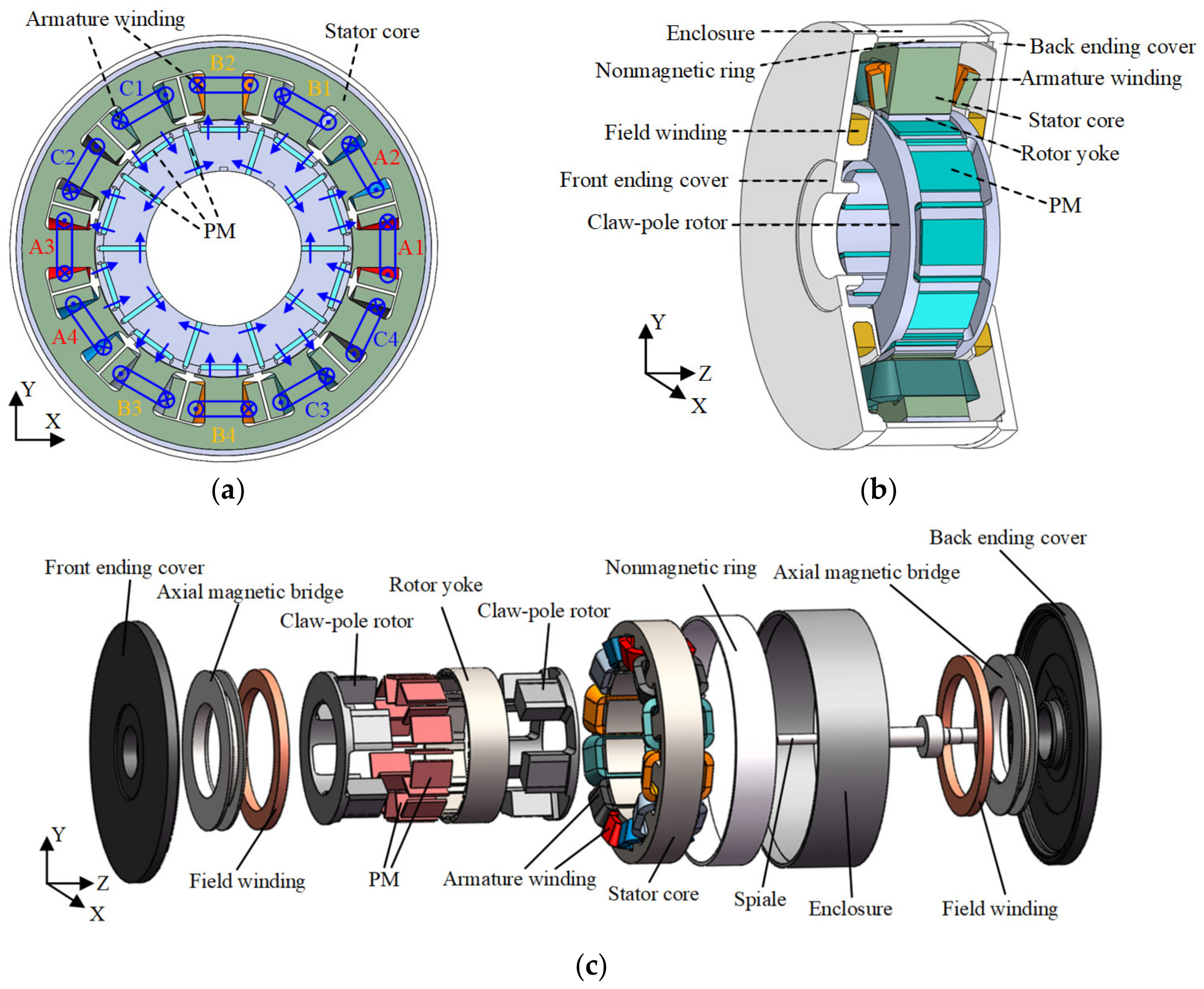
2. Machine Configuration and Flux Path

2.1. Machine Configuration

The configuration of the proposed HE-CPM is shown in Figure 1. The generator mainly consists of the stator core, claw-pole rotor, nonmagnetic ring, front and back ending covers and enclosure. The stator core is formed by axial lamination of silicon steel sheets, twelve armature coils are wounded in stator slots, and the current polarities are shown by blue dots and crosses in Figure 1a. The rotor part is composed of two mutually nested claw-pole rotors, PMs and rotor yoke, as shown in Figure 1b,c. PMs are inserted in the two claw-pole rotors, and the magnetization directions of PMs are shown by the blue arrows in Figure 1a. The rotor yoke is sleeved on the two mutually nested claw-pole rotors. Two field windings are placed in front and back ending covers, respectively, and they are connected in series.
The structural advantages of the proposed HE-CPM are summarized as follows:
(1)
The size of the slot formed by the two claw-pole rotors exactly matches the size of PM. Therefore, no glue is needed when assembling the rotor, which is more environmentally friendly. The noise when the rotor moves is also reduced.
(2)
The field winding is placed at the end cover of the proposed HE-CPM. Compared with the hybrid excitation machine with the field winding placed on the stator, placing the field winding at the end cover can reduce the complexity of machine configuration.

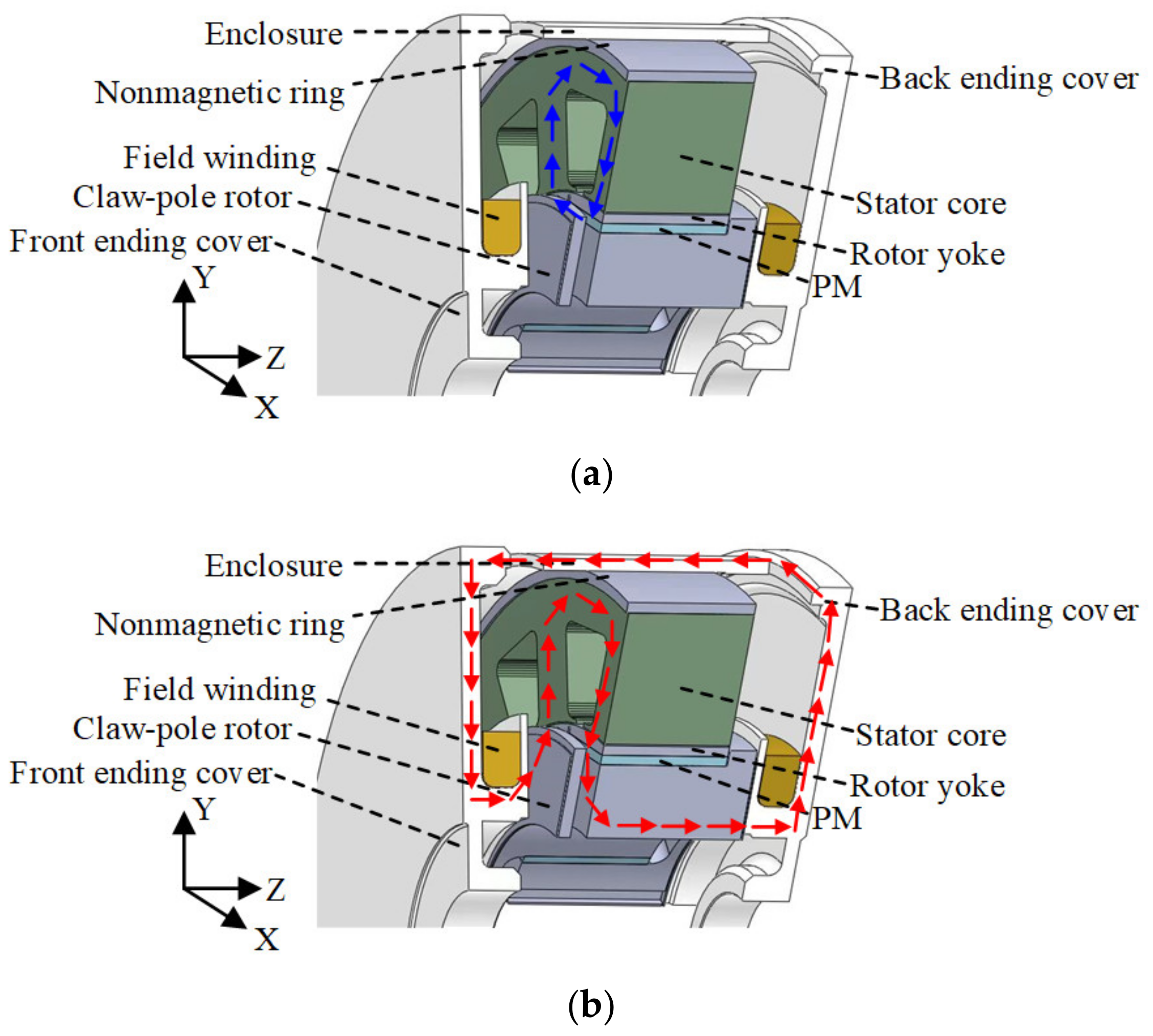
2.2. Hybrid Flux Path
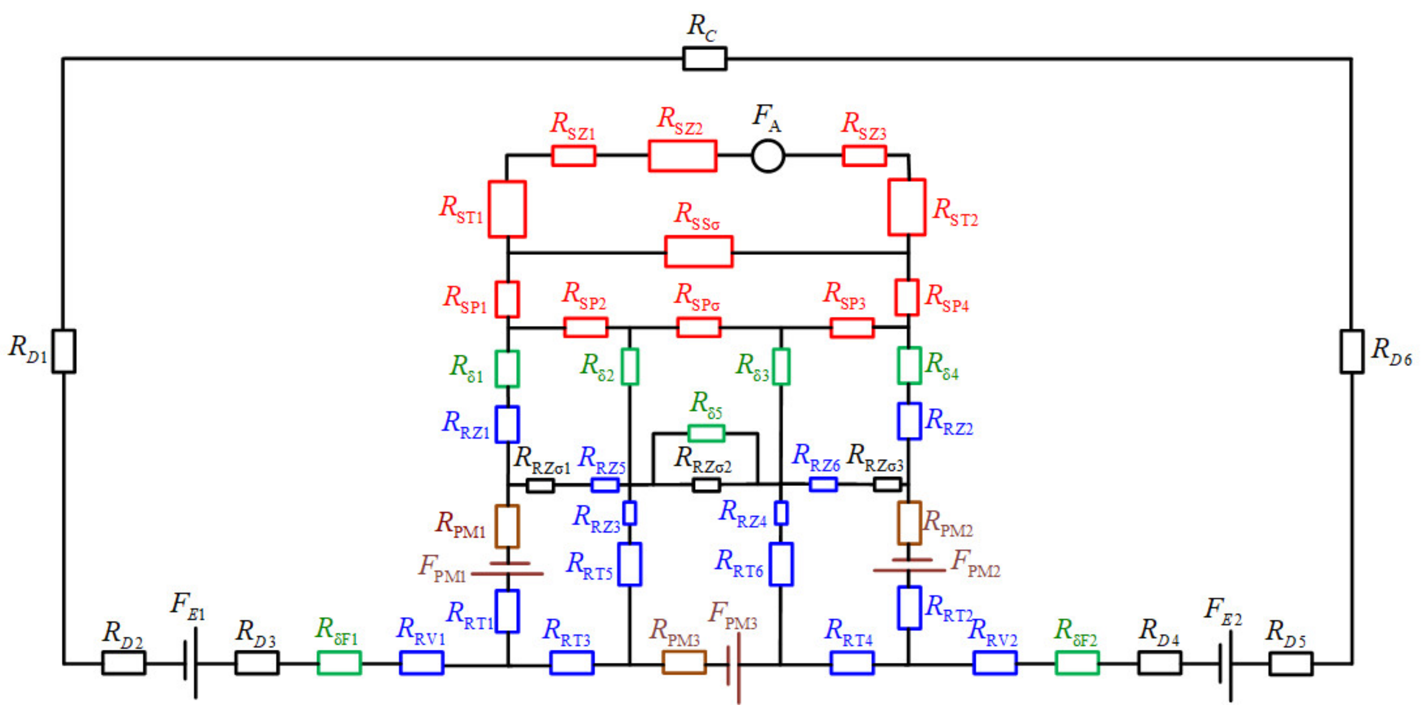
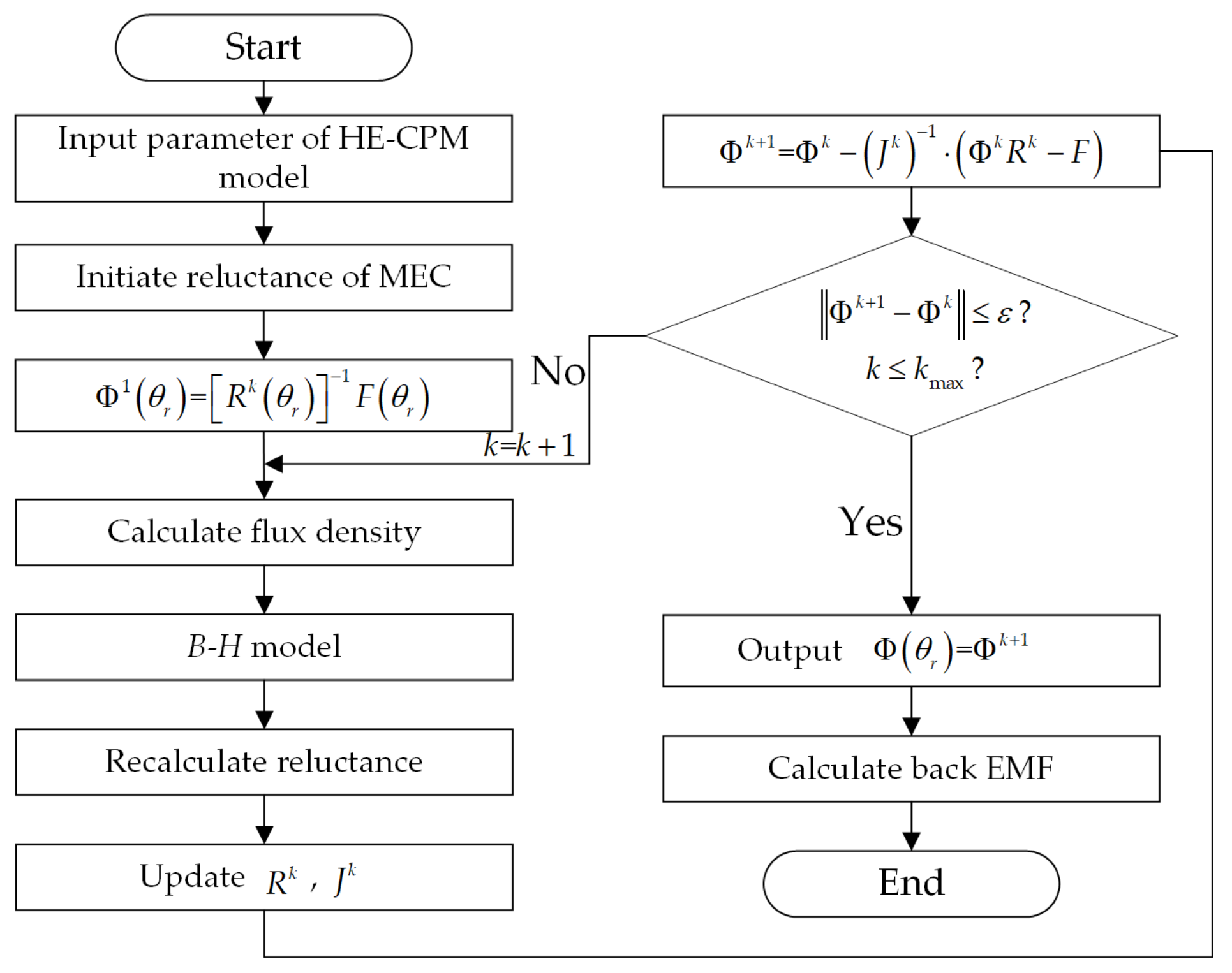
The hybrid flux path in HE-CPM is shown in Figure 2. The PM field is the main magnetic field, and the PM excitation flux path is indicated by the blue arrow in Figure 2a. The PM excitation flux passes through claw-pole rotor finger, rotor yoke, main air gap, stator tooth, stator yoke, adjacent stator tooth, main air gap, rotor yoke, claw-pole rotor finger. The field excitation flux path is indicated by the red arrow in Figure 2b. The field excitation flux passes through claw-pole rotor finger, rotor yoke, main air gap, stator tooth, stator yoke, adjacent stator tooth, main air gap, rotor yoke, claw-pole rotor finger, back axial magnetic bridge, back ending cover, enclosure, front-ending cover, front axial magnetic bridge, claw-pole rotor finger. The field excitation flux plays an auxiliary and modulation role, and the hybrid flux path is parallel.

3. MEC Model

The closed-loop MEC under a pair of magnetic poles at the initial rotor position is modeled, as shown in Figure 3. The stator-related items are marked in red. The rotor-related items are marked in blue. The PM-related items are marked in gray, including PM equivalent internal reluctance and PM equivalent magnetomotive force (MMF) source. The air gap-related items are marked in cyan. Different items in MEC are listed in Table 1.
Based on Ohm’s law of magnetic circuits, the MMF in MEC can be expressed as:
F = Φ R
where F , Φ , R are MMF, magnetic flux, reluctance in magnetic circuits, respectively.
The MMFs in HE-CPM are provided by PM and field winding. So, the MMF obtained from PM can be expressed as:
F P M = H c h P M
where H c is the intrinsic coercivity of magnet, h P M is the PM length in magnetization direction.
The MMF obtained from field winding can be expressed as:
F E = N f I f
where N f is the turns of the field winding, I f is the excitation current.
The machine configuration is complex, so it is necessary to select the appropriate equivalent shape of each reluctance. In order to facilitate the calculation, the reluctances which are derived from the above MEC model are equivalent to the common cube shape and several other shapes shown in Figure 4. The dotted line with an arrow indicates the direction of magnetic flux.
R S Z 2 , R S T , R S P 1 , R S P 4 , R S P σ , R δ 1 ~ R δ 4 , R R Z 1 , R R Z 2 , R P M , R R T 1 , R R T 2 can be equivalent to common cube shape, and the reluctance can be expressed as:
R c u b = L m μ 0 μ s S m
where L m is the path length of magnetic flux. μ 0 is the permeability of the vacuum. μ s is the relative permeability. S m is the cross-sectional area of the magnetic flux path.
R S S σ , R δ 5 , R R Z σ , R R Z 5 , R R Z 6 , R R T 3 , R R T 4 can be equivalent to tile shape, as shown in Figure 4a, and the reluctance can be expressed as:
R t i l = α μ 0 μ s h 2 l n r s 2 r s 1
where α is the angle between non-parallel planes in the tile shape. h 2 is the axial length of the tile. r s 2 , r s 1 are the outer radius and inner radius of tile, respectively.
R S Z 1 , R S Z 3 , R S P 2 , R S P 3 , R R Z 3 , R R Z 4 , R R T 5 , R R T 6 can be equivalent to vertical plane shape, as shown in Figure 4b, and the reluctance can be expressed as:
R p l a = π d 1 + d 2 μ 0 μ s 2 l d 1 l n 1 + d 2 t   +   d 2 l n 1 + d 1 t
where t is the distance between two planes. l is the radial arc length. d 1 , d 2 are the width of two planes, respectively.
R D 1 , R D 6 can be equivalent to a concentric cylinder shape, as shown in Figure 4c, and the reluctance can be expressed as:
R c y l = l n r 2 r 1 2 μ 0 μ s h π
where h is the length of the cylinder. r 1 , r 2 are the inner radius and outer radius of the cylinder, respectively.
R C , R D 2 ~ R D 5 , R δ F 1 , R δ F 2 , R R V 1 , R R V 2 can be equivalent to parallel torus shape, as shown in Figure 4d, and the reluctance can be expressed as:
R t o r = h c μ 0 μ s π r c 2 2 r c 1 2
where h c is the distance between parallel rings. r c 1 , r c 2 are the inner radius and outer radius of the torus, respectively.
According to Figure 3, the following nonlinear equations can be obtained:
F n l × 1 = Φ n l × 1 R n l × n l
where F is the MMF source vector. Φ is loop flux vector. R is a symmetric matrix composed of reluctance. n l is the number of flux loops.
Loop flux vector Φ can be expanded as:
Φ = Φ s t 1     Φ s t n s   Φ r t 1   Φ a t 1   Φ a g 1     Φ a g n a T
where the subscripts s t , r t , a t and a g indicate loop fluxes in the stator tooth, rotor tooth, axial auxiliary air gap and main air gap, respectively, and the subscripts n s and n a indicate the number of stator and air gap loops, respectively. Similarly, the MMF source vector F is expanded as:
F = F s t 1     F s t n s   F P M 1   F D E   0 1 × n a T
The reluctance matrix R can be expressed as:
R = R s t n s × n s 0 0 R P M   0 R a g , s t n s × n a θ r R P M , D E R a g , P M 1 × n a θ r 0 R P M , D E T R a g , s t T R a g , P M T   R D E R a g , D E 1 × n a θ r R a g , D E T R a g n a × n a θ r
where R s t and R P M are derived from the stator and rotor loops. R D E is derived from the axial flux loop. R a g , s t , R a g , P M , R a g , D E , R a g are related to rotor position.
At the initial position of rotor (k = 0):
Φ 1 θ r   = R k θ r 1 F θ r
When k > 0, the following can be derived:
Φ k + 1 = Φ k J k 1 · Φ k R k F
where J is the Jacobian matrix and k is the iteration number.
The flow chart of 3D MEC is shown in Figure 5. According to Figure 3 and Equations (4)–(8), the initial reluctance matrix can be calculated. Then, the flux of the initial position Φ 1 θ r can be obtained from (13). Perform iterative calculation according to (14), and update R k , J k when the rotor moves to the next position. When the difference between Φ k + 1 and Φ k is within the allowable range, the solution of rotor position is obtained. With the change of rotor position, R k and J k will change accordingly. Therefore, the proposed MEC is a 3D MEC that is related to the position of the rotor.
Finally, according to the Φ θ r calculated by 3D MEC, the back EMF can be obtained:
E = N a ω Φ θ r 2
where N a is the number of turns of armature winding per phase. ω is the angular frequency.
The no-load characteristic derived from FEA and the no-load characteristic calculated by using the proposed 3D MEC are compared in Figure 6. With the increase of excitation current, the back EMF also increases. A good agreement between both characteristics can clearly be noticed. By changing the excitation current, the back EMF can be adjusted, and the generator output power can be modulated.

4. Optimization of Dimension Parameters

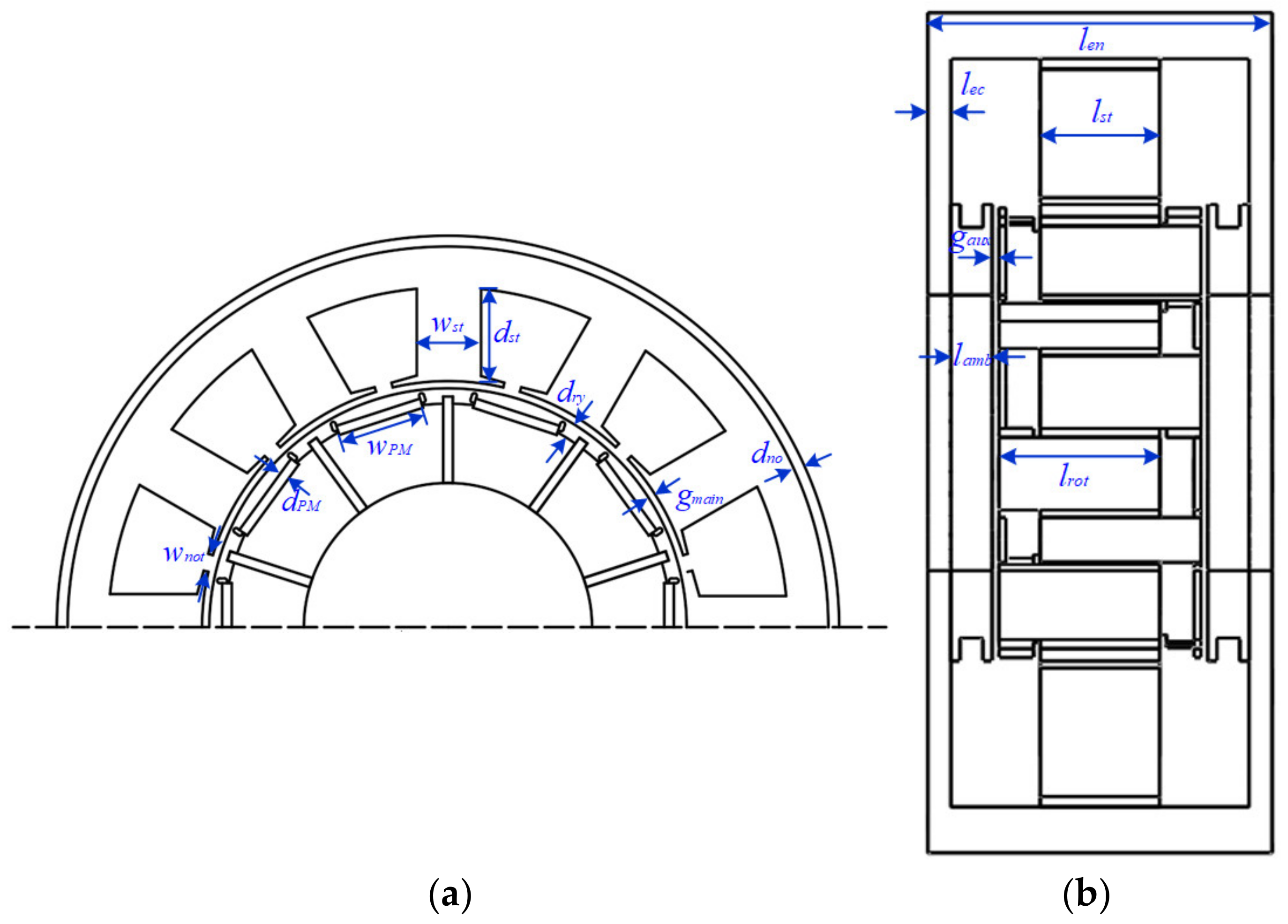
4.1. Machine Parameters Definition and Selection

The HE-CPM is designed to be used in EV and the requirements are: (1) Rated power ≥ 10 kW; (2) Efficiency ≥ 85%; (3) Maximum operating temperature < 90 degrees centigrade.
The dimension parameters of HE-CPM are defined in Figure 7 and are listed in Table 2. After that, the parameters that have a major influence on the machine performance will be selected and optimized to obtain better machine performance. Finally, the results before and after optimization will be compared to verify the effectiveness of the optimization algorithm and 3D MEC.
Generally, the generator in EV application should have: (1) High torque density to meet the requirements during start-up; (2) Low torque ripple to reduce noise; (3) Low loss to increase efficiency. So, three objectives are selected during optimization, which are the average torque f1, torque ripple f2, and loss f3. The optimization problem can be expressed as:
min f 1 x , f 2 x , f 3 x ,   x ϵ F
where x refers to the dimension parameters, and F refers to the constraints of dimension parameters.
The proposed HE-CPM is a dual three-phase machine, so the torque can be expressed as:
T o u t t   = n = A 1 , B 1 , C 1 e t i t   + n = A 2 , B 2 , C 2 e t i t ω r
where e t and i t are phase back EMF and current, respectively. ω r is angular velocity.
The torque ripple can be expressed as:
T r t   = m a x T o u t t m i n T o u t t A v g T o u t t
where m a x T o u t t and m i n T o u t t are the maximum value and minimum value of torque, respectively. A v g T o u t t is the average value of torque.
The iron loss p i r o n consists of hysteresis loss p h , eddy current loss p e c , and excess loss p e :
p i r o n = p h + p e c + p e = k h f B m α + k e c f 2 B m 2 + k e f 1.5 B m 1.5
where k h , k e c , and k e are the hysteresis, eddy current, and excess loss coefficients, respectively. B m is the maximum flux density.
The three design objectives (i.e., torque, torque ripple, loss) are closely influenced by the MMF and air gap permeance [12], and the relationship between them and wPM, wnot, wst, dPM, dry, dst, gmain can be obtained from [12]. The PM MMF, field excitation equivalent MMF and air-gap permeance are determined by the seven dimension parameters (i.e., wPM, wnot, wst, dPM, dry, dst, gmain). Therefore, the seven dimension parameters are selected as the parameters to be optimized.

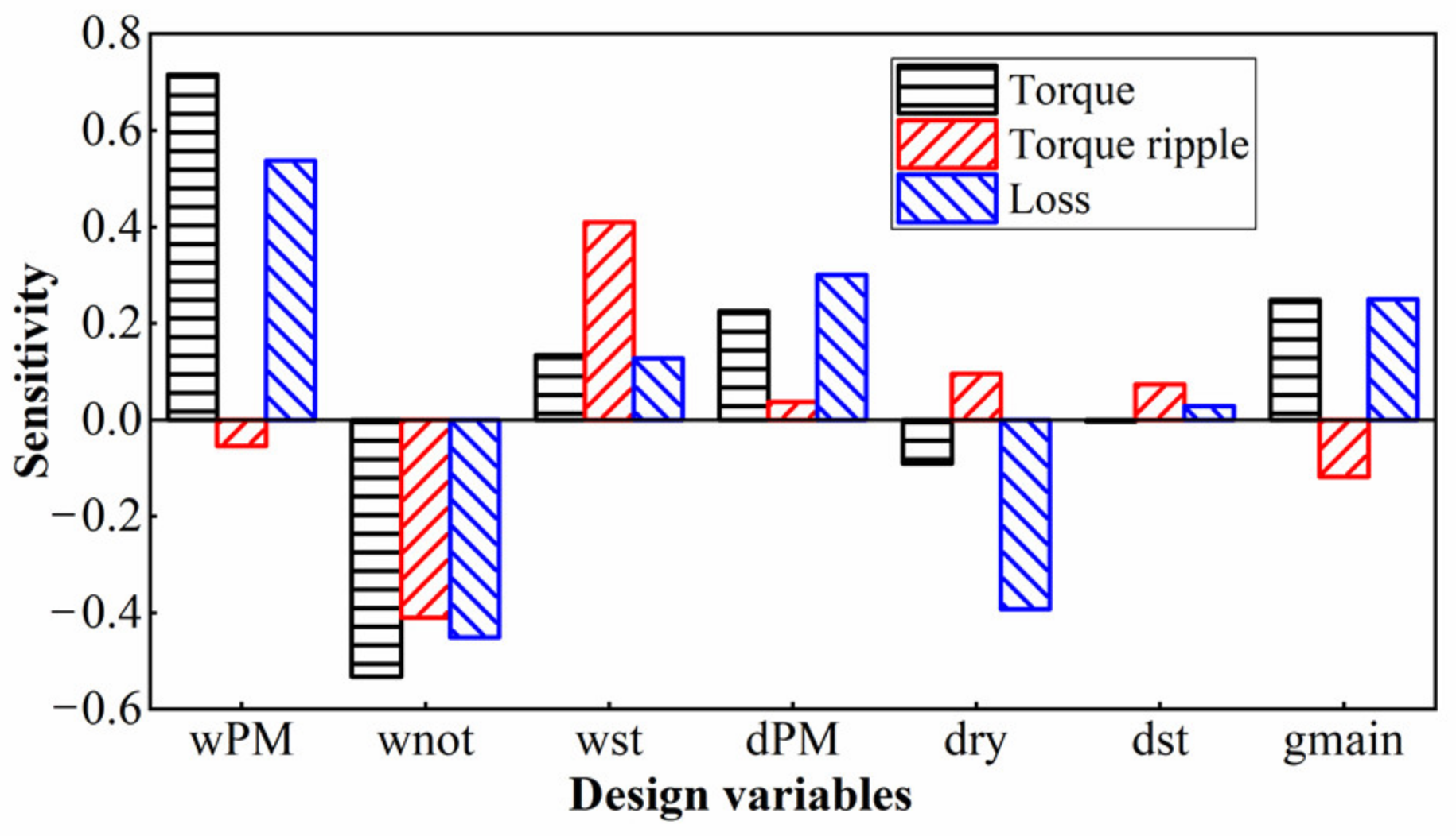
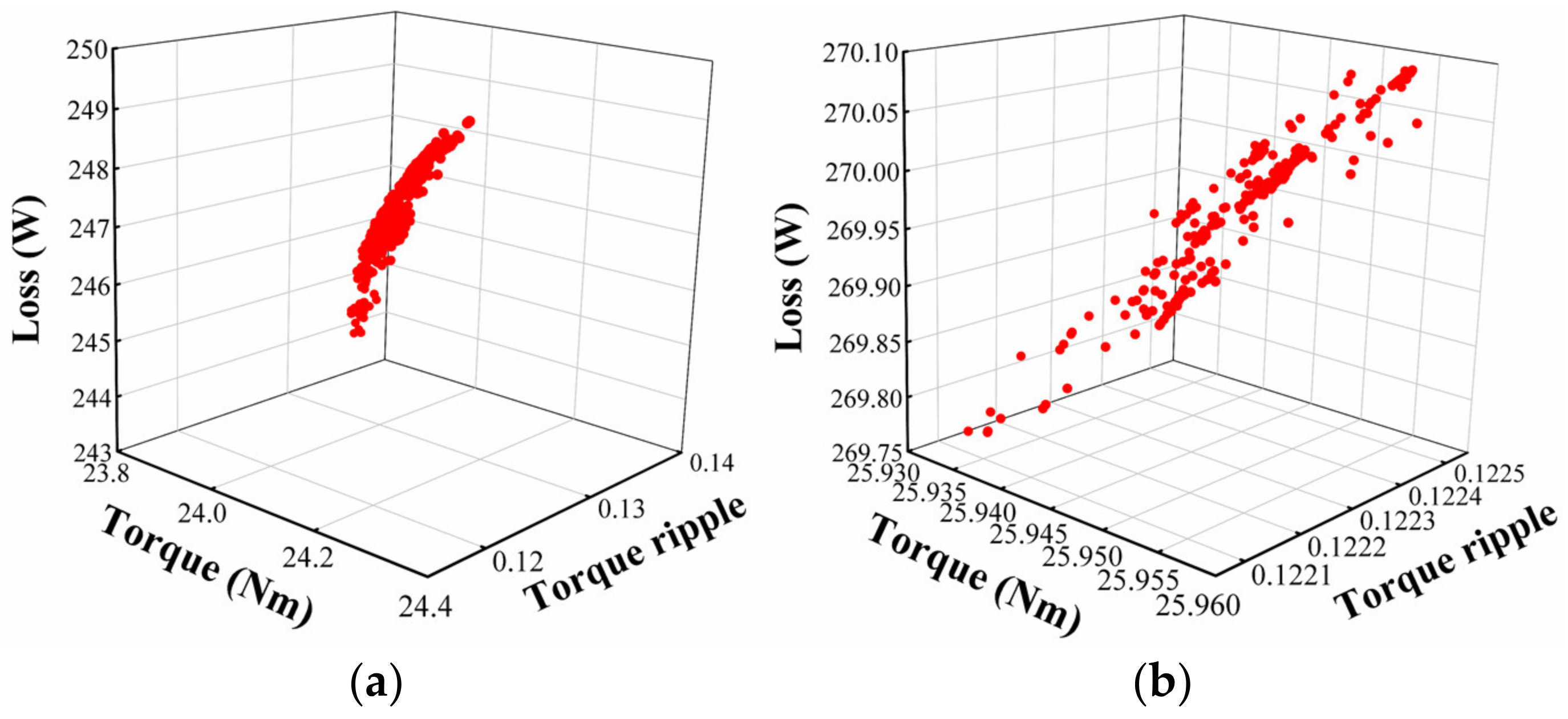
4.2. Machine Parameters Optimization

Each dimension parameter has a different influence on different objectives, the sensitivity analysis method (SAM) is one of the most effective methods to analyze and measure the influence of each variable on the optimization objectives. Generally, the sensitivity of the ith parameter xi at point x0 is defined as:
S i = y x x i | x = x 0
where S i is sensitivity, y x is the objective function.
Therefore, the sensitivity of wPM, wnot, wst, dPM, dry, dst, gmain can be obtained by calculating the derivative of the objective function. The greater the value of sensitivity, the greater the influence of dimension parameters on optimization objectives. If the dimension parameter has a positive sensitivity value, it indicates that the optimization objective will increase with the increase of dimension parameter; if the design variable has a negative sensitivity value, it indicates that the optimization objective will decrease with the increase of dimension parameter.
The sensitivity analysis results of different design variables are shown in Figure 8. The comprehensive sensitivity of design variables to optimization objectives can be expressed as:
S i = ω t S t x i + ω t r S t r x i + ω l S l x i
where S i is the comprehensive sensitivity of HE-CPM, x i is the design variable, and S t x i , S t r x i and S l x i are the sensitivity of the design variable to torque, torque ripple and loss, respectively. ω t , ω t r and ω l are the weight coefficients of torque, torque ripple and loss, respectively. When determining the specific numerical values of w, it must be noted that the sum of ω t , ω t r and ω l must be 1. Then, if we want to obtain higher torque and less loss, we could set ω t and ω l to 0.4 and ω t r to 0.2 (The sum of three coefficients must be 1). In this case, we can obtain higher torque and less loss. Then, if we want to achieve a smaller torque ripple and loss, we can set ω t to 0.2 and ω t r and ω l to 0.4. In this case, the result will have smaller torque ripple and loss, but the torque will also be lower. We can also set ω t , ω t r and ω l to 1/3, which means the result will achieve a relative balance in torque, torque ripple and loss. Therefore, it mainly depends on which of the three objective functions we pay more attention to. In our design, torque and loss are more concerned, so we set ω t and ω l to 0.4 and ω t r to 0.2. The sensitivities of these design variables are shown in Table 3.
According to the sensitivity from high to low, classify the design variables into three levels, A: wPM (0.512), wnot (0.4174), gmain (0.2234). B: dPM (0.2178), dry (0.2128). C: wst (0.1862), dst (0.0276). Because the sensitivity of level C is low, the initial values of wst and dst in level C are used. The three parameters in level A are optimized, and then the two parameters in level B are optimized. Three-dimensional (3D) FEA is time-consuming, so particle swarm optimization (PSO) is used for optimization in combination with 3D MEC.
Based on the observation of the activity behavior of animal clusters, the PSO algorithm uses the information sharing of individuals in the group to make the movement of the whole group produce an evolutionary process from disorder to order in the problem-solving space, so as to obtain the optimal solution [22].
PSO is initialized as a group of random particles (random solutions). Then the optimal solution is found through iteration. In each iteration, the particles update themselves by tracking two optimal values (pbest, gbest). After finding these two optimal values, the particle updates its speed and position:
v i = v i + c 1 × r a n d   × p b e s t i x i   +   c 2 × r a n d   × g b e s t i x i
x i = x i + v i
where i = 1,2,…,N; N is the total number of particles. vi is the speed of particles. rand() is a random number between 0 and 1. xi is the current position of particles. c1 and c2 are the learning factors. pbest is the local optimal value. gbest is the global optimal value.
Firstly, the three design variables of level A are optimized, and the resulting Pareto solution set is shown in Figure 9a. It can be seen that the corresponding torque is about 24 Nm and the torque ripple is 0.12 to 0.13. The loss is about 245 W. After optimizing the three design variables in level A, the two design variables of level B are optimized, and the resulting Pareto solution set is shown in Figure 9b. It can be seen that the torque increases to 25.95 Nm, the torque ripple is stable at about 0.122, but the loss increases to about 270 W.
The dimension parameter optimization results in levels A and B are shown in Table 4. Then, the parameters before and after optimization are used in 3D FEA, respectively. Their results are compared.
FEA results before and after optimization are shown in Figure 10, and the torque ripples are listed in Table 5. It can be seen that the average torque has increased from 26.1 Nm to 28.3 Nm and the torque ripple has decreased from 28.4% to 22.6%. The hysteresis loss has decreased by 8.7% and the eddy current loss has decreased by 9.9%. The FEA results verify the effectiveness of the optimization algorithm combined with 3D MEC for machine optimization.

5. Machine Performance Evaluation

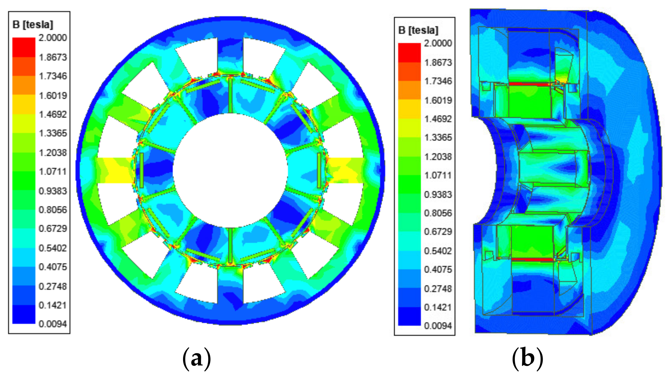
5.1. Flux Density Distribution

The no-load flux distribution of the proposed HE-CPM is shown in Figure 11. It can be seen that the highest magnetic flux density is in the stator shoe and its value is 1.87 T.

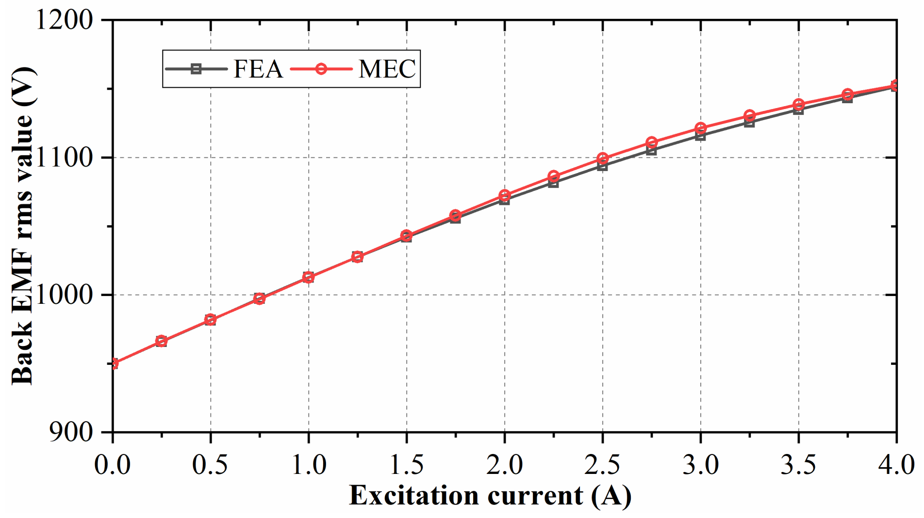
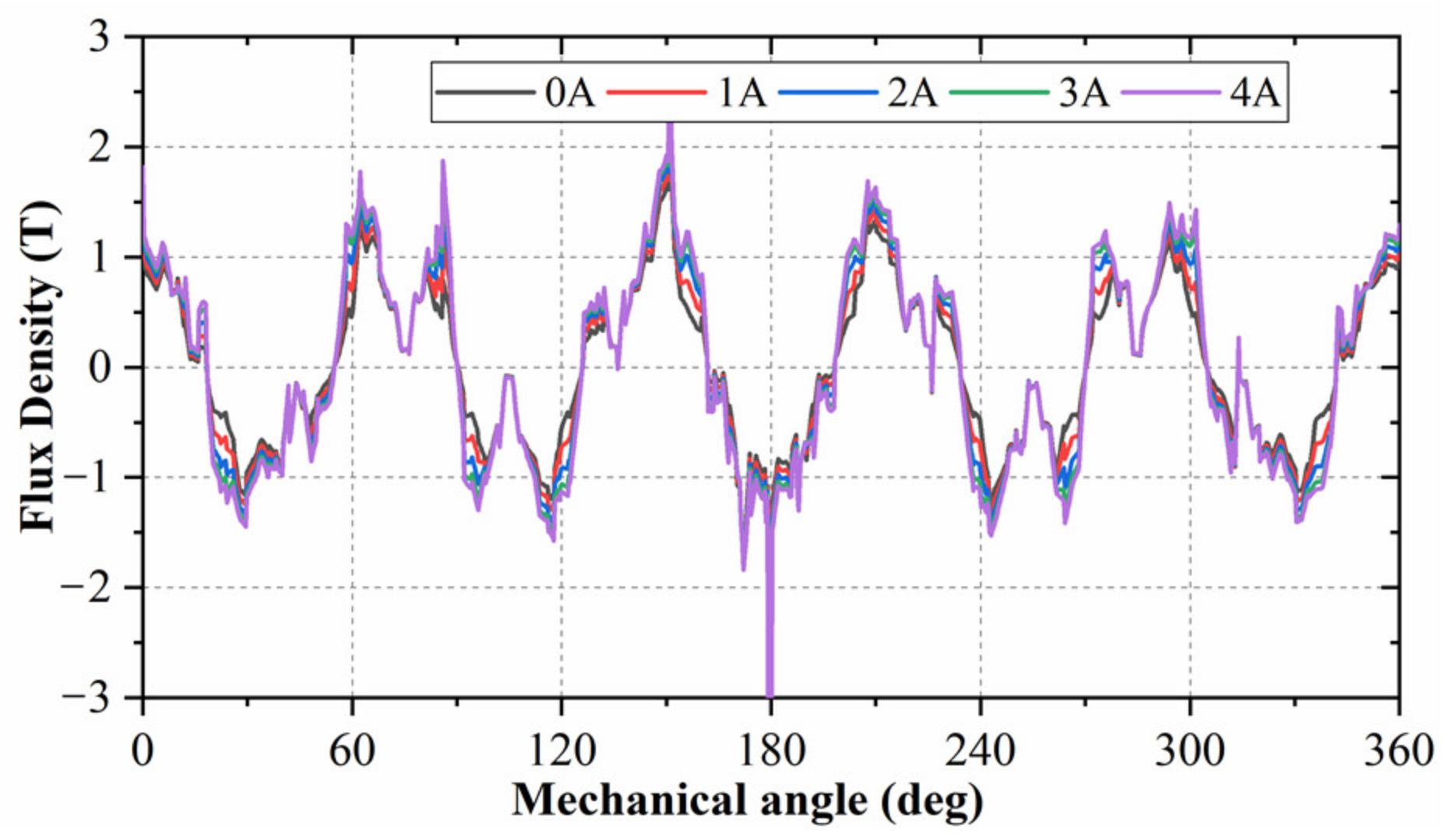
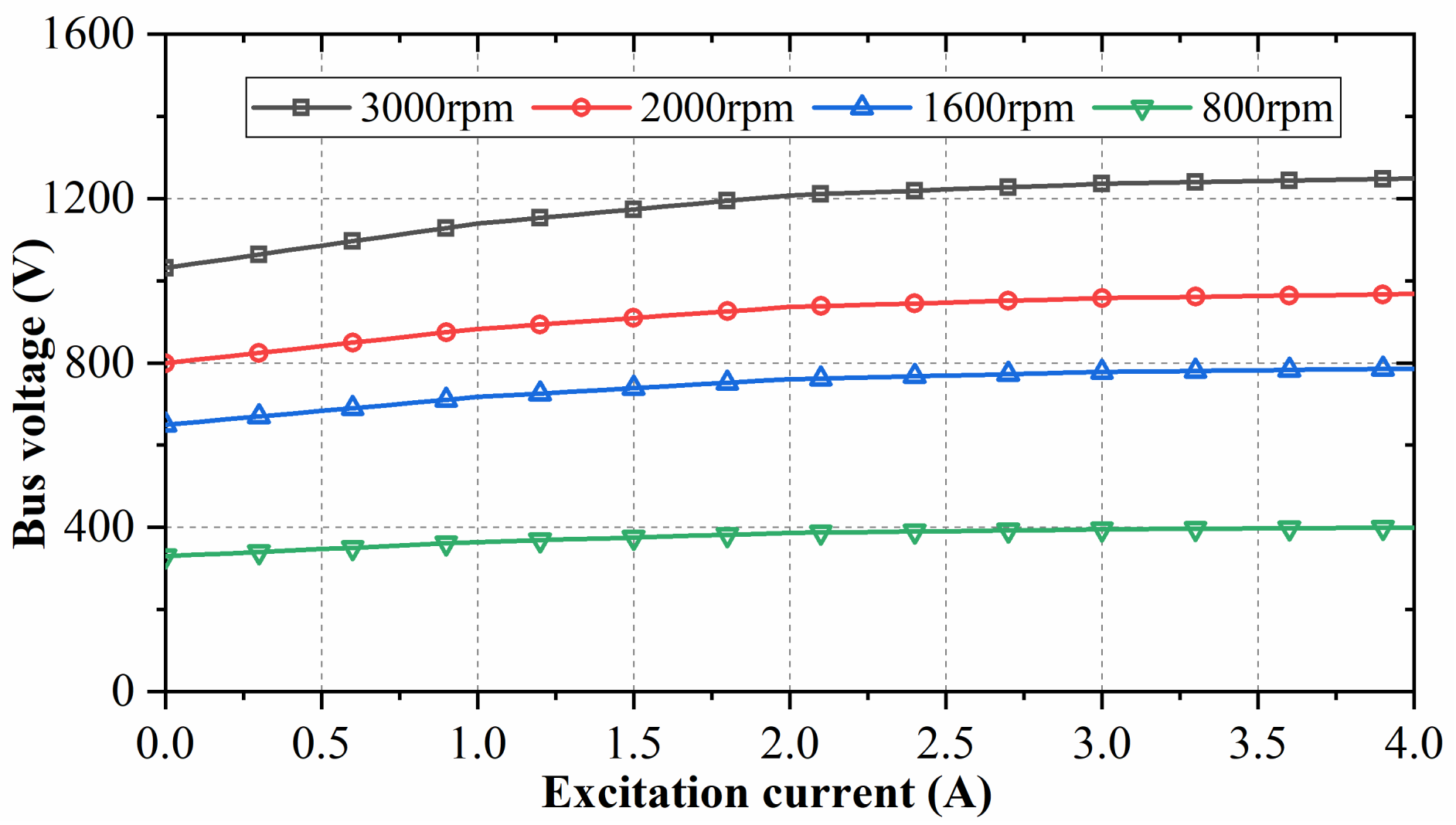
5.2. Electromagnetic Characteristics

The magnetic flux density of the main air gap under different excitation currents is shown in Figure 12. The magnetic flux density produced by PM in the main air gap is 0.9 T, which is distributed periodically along the circumferential direction of the main air gap. When the excitation currents are 1 A, 2 A, 3 A, 4 A, the maximum flux densities are 0.977 T, 1.05 T, 1.11 T, 1.15 T, respectively. It can be seen that when the excitation current increases gradually, the flux density of the main air gap also rises. Therefore, the flux density of the main air gap can be adjusted by changing the excitation current.
The no-load back EMF is shown in Figure 13. The generator is a dual three-phase machine, therefore, two sets of three-phase back EMF can be obtained. It can be seen that the difference between A1 and A2 back EMF is 30 degrees, and the amplitude of phase voltage is 768 V. According to (17), the generator output power P o u t is obtained by multiplying the back EMF e t by the current i t , and the power divided by the angular velocity ω r is the generator output torque T o u t t . Therefore, the back EMF will directly affect the power and torque. We can change the excitation current to adjust the back EMF, and finally, adjust the generator output power. Because our machine is a generator, we pay more attention to the sinusoidal degree of the back EMF. If the back EMF has large harmonics, it will lead to the large cogging torque of the generator, which will directly lead to the large ripple of the generator output torque. However, we want to get a stable and large output torque.
The relationship between bus voltage and excitation current is shown in Figure 14. With the increase of excitation current, the bus voltage increases. When the speed decreases, the voltage also decreases. When the speed is 3000 rpm and the excitation current is 4 A, the DC voltage is about 1250 V. The rated speed of HE-CPM is 3000 rpm.
The relationship between bus voltage and the load current is shown in Figure 15. With the increase of load current, the bus voltage decreases. Increasing the excitation current from 0 A to 4 A can significantly increase the bus voltage.

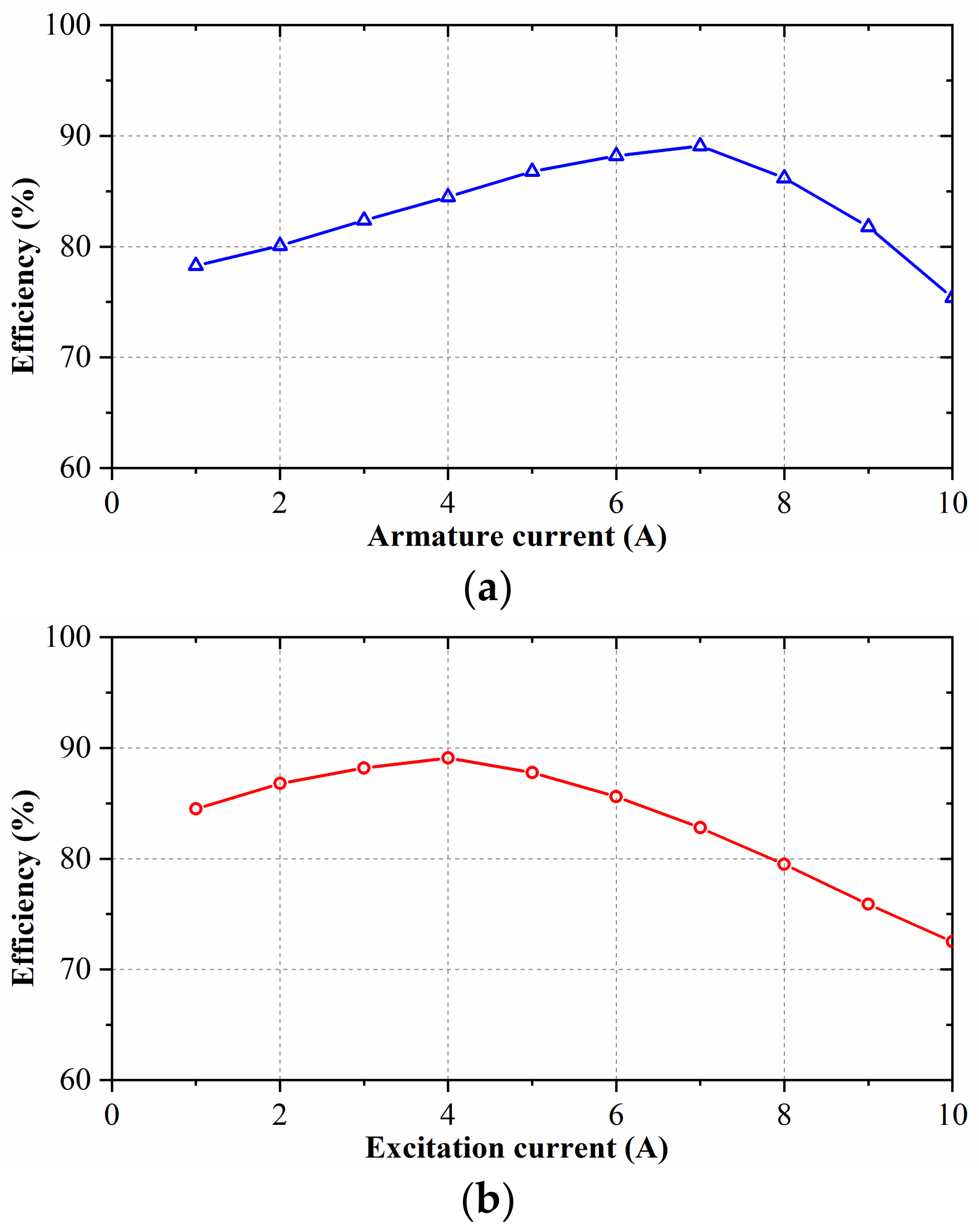
5.3. Loss and Efficiency

The iron loss is calculated in (19), the copper loss is related to the resistance and current, and can be expressed as:
p c u = M N I 2 R c u = M N I 2 ρ c u l c u S c u
where R c u is resistance. I is current. ρ c u is the copper resistivity. l c u is the length of a single wire. S c u is the cross-sectional area of the wire. M is the slot number. N is the turns of the winding. For armature winding, N is Na. For field winding, N is Nf.
Considering the change of copper resistivity caused by temperature, the copper resistivity can be expressed as [23]:
ρ c u = ρ c u 20 1 + α T T 20
where ρ c u 20 is the copper resistivity at temperature T 20 = 20   , and the value is 1.7 × 10⁻⁸ Ωm. α is the temperature coefficient of copper resistivity, and the value is 3.93 × 10⁻³ K−1.
The output power P o u t can be expressed as:
P o u t = T o u t t ω r
The efficiency η can be expressed as:
η = P o u t P i n × 100 % = P a v g p i r o n P a v g + p c u × 100 %
where P i n is the input power. P a v g is the average electromagnetic power.
The relationship between efficiency and armature current and the excitation current is shown in Figure 16. It can be seen that with the increase of current, the efficiency first increases and then decreases. The rapid increase of copper loss is the main reason for the decrease in efficiency. The maximum machine efficiency is 89%.

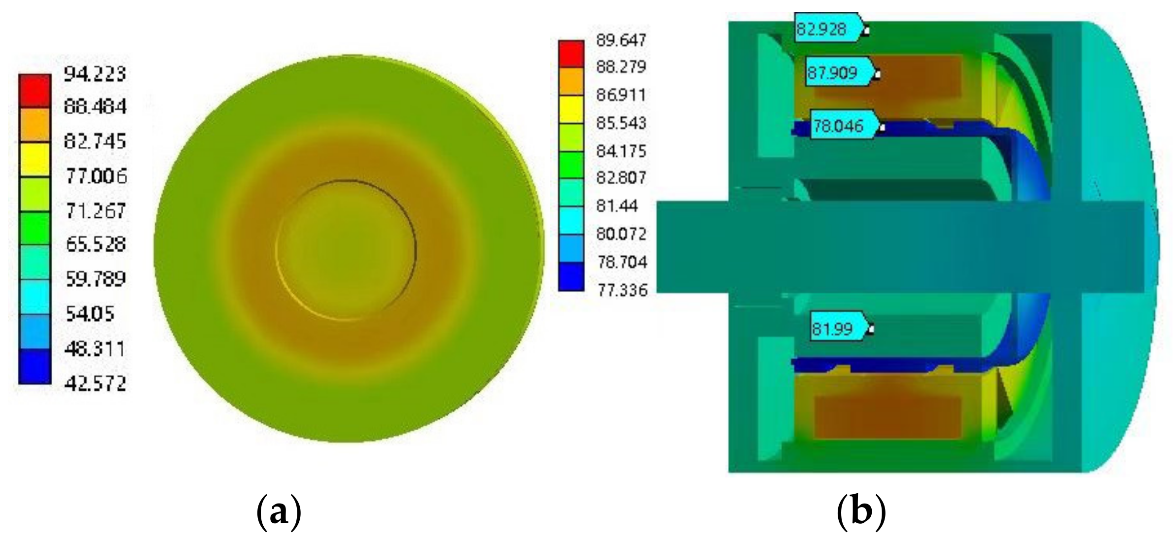
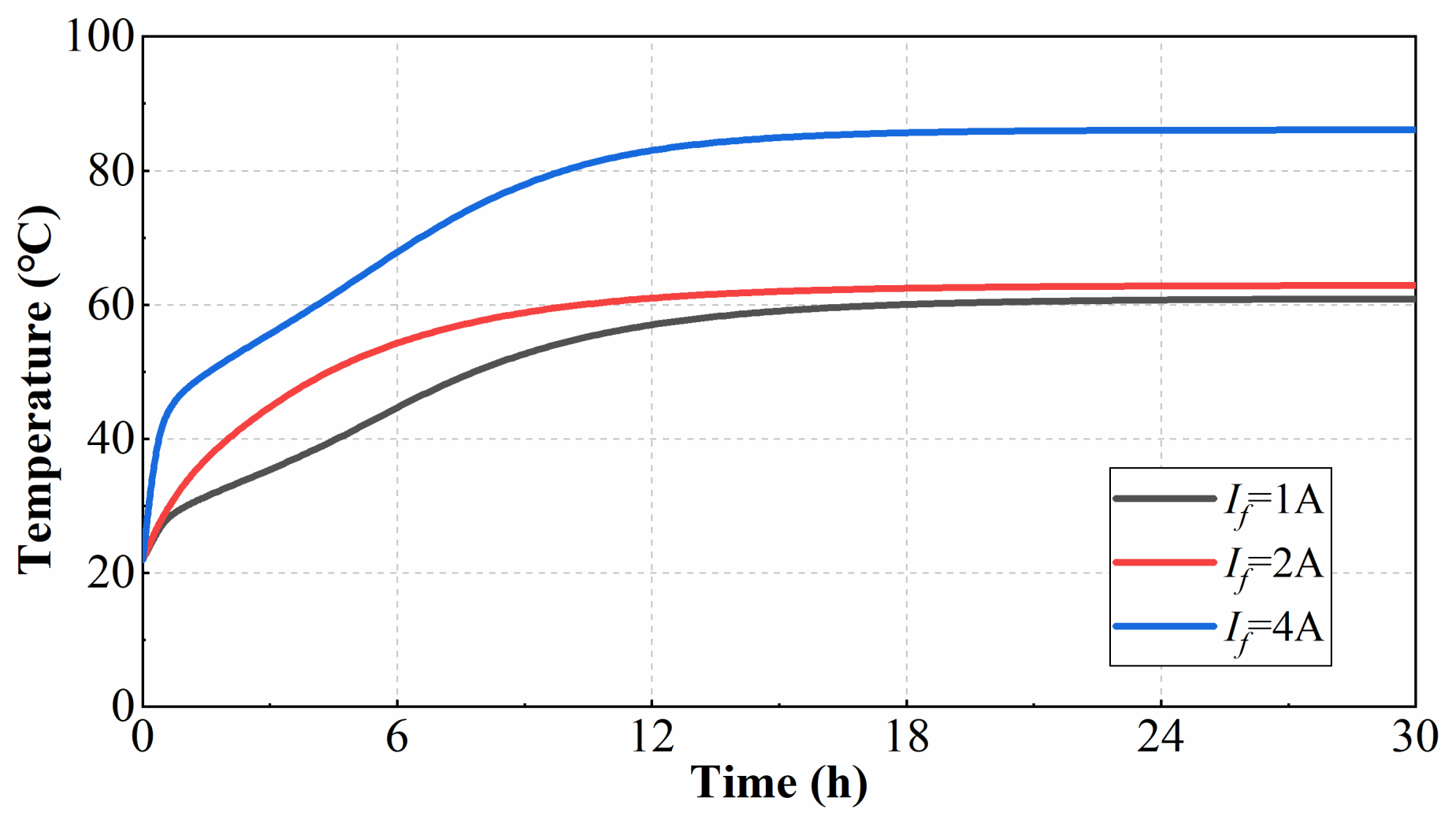
5.4. Temperature Field Simulation

The temperature of each part of HE-CPM needs to be analyzed to ensure that the temperature is within the allowable range when the generator is working. The temperature of each part of the machine should not exceed 90 degrees centigrade. The temperature field nephogram of HE-CPM is shown in Figure 17. It can be seen that the maximum temperature is 87.909 degrees centigrade, and the position is the field winding which is placed in the axial magnetic bridge. When the excitation current increases, the temperature of the axial magnetic bridge will rise, so the temperature of the axial magnetic bridge at different excitation currents is shown in Figure 18. It can be seen that when the excitation current increases from 1 A to 4 A, the temperature increases from 60.6 degrees centigrade to 87.909 degrees centigrade. The temperature curve of the axial magnetic bridge is shown in Figure 19.
It can be seen from Figure 17, Figure 18 and Figure 19 that the maximum operating temperature of field winding is 87.909 degrees centigrade. The field winding consists of copper wires. Based on (25), the copper resistivity at temperature 87.909 degrees centigrade can be calculated, and ρ c u = 1.267 ρ c u 20 = 2.1539 × 10 8   Ω m . It can be seen from (24) that the copper loss p c u is proportional to ρ c u . Therefore, the copper loss p c u at 87.909 degrees centigrade is 1.267 times that of the copper loss at 20 degrees centigrade. The lower the temperature, the smaller the copper loss. It can be seen from (27) that the efficiency is improved when the copper loss is reduced. Therefore, the maximum operating temperature of the machine should be as low as possible.

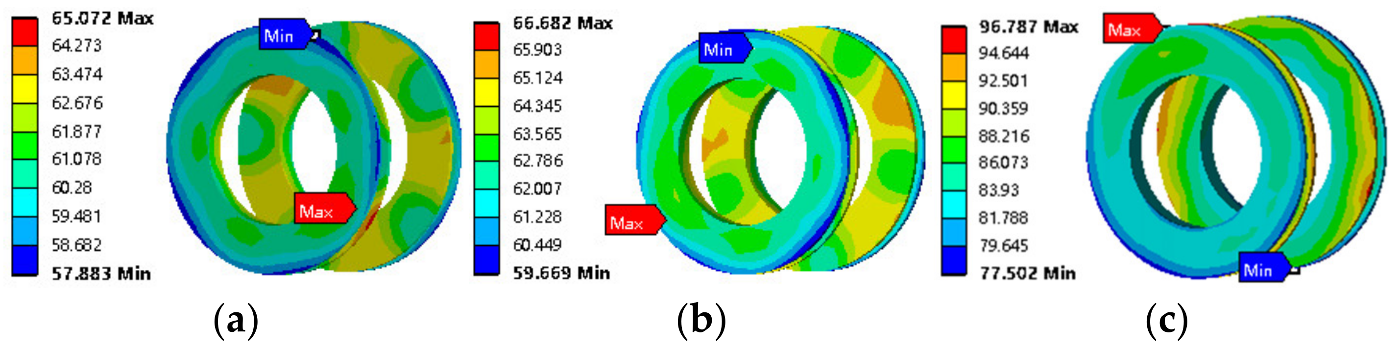
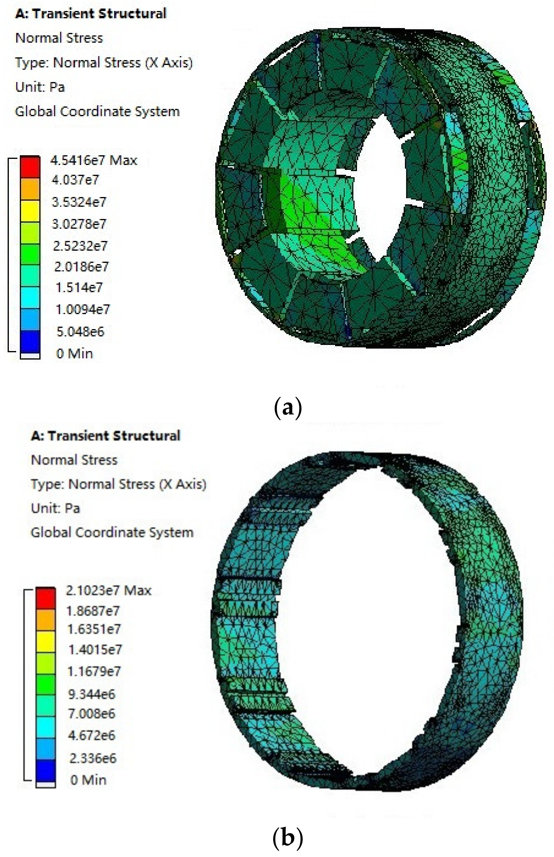
5.5. Mechanical Stress

The mechanical stress of the rotor needs to be analyzed by FEA to ensure that the proposed HE-CPM can work at the rated speed (3000 rpm). The material parameters of the rotor yoke are listed in Table 6 [24]. The mechanical stress nephogram of HE-CPM is shown in Figure 20. The simulation condition is transient mechanical stress simulation, and the unit is Pa. The maximum mechanical stress of the rotor is 45.4 MPa, while the maximum stress of the rotor yoke is 21 MPa. The maximum mechanical stress obtained from FEA is less than allowable stress (800 MPa), so the rotor can sustain under the rated speed (3000 rpm).

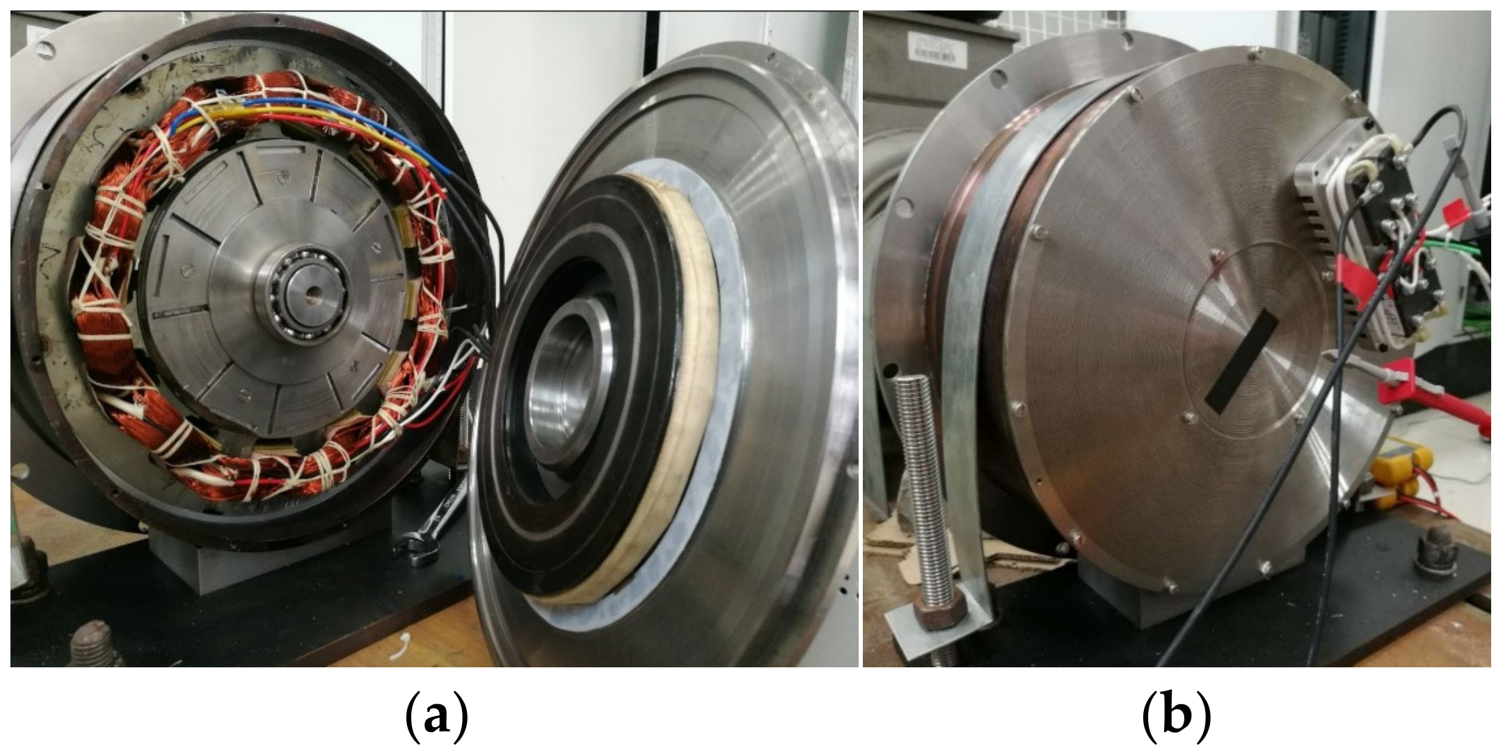
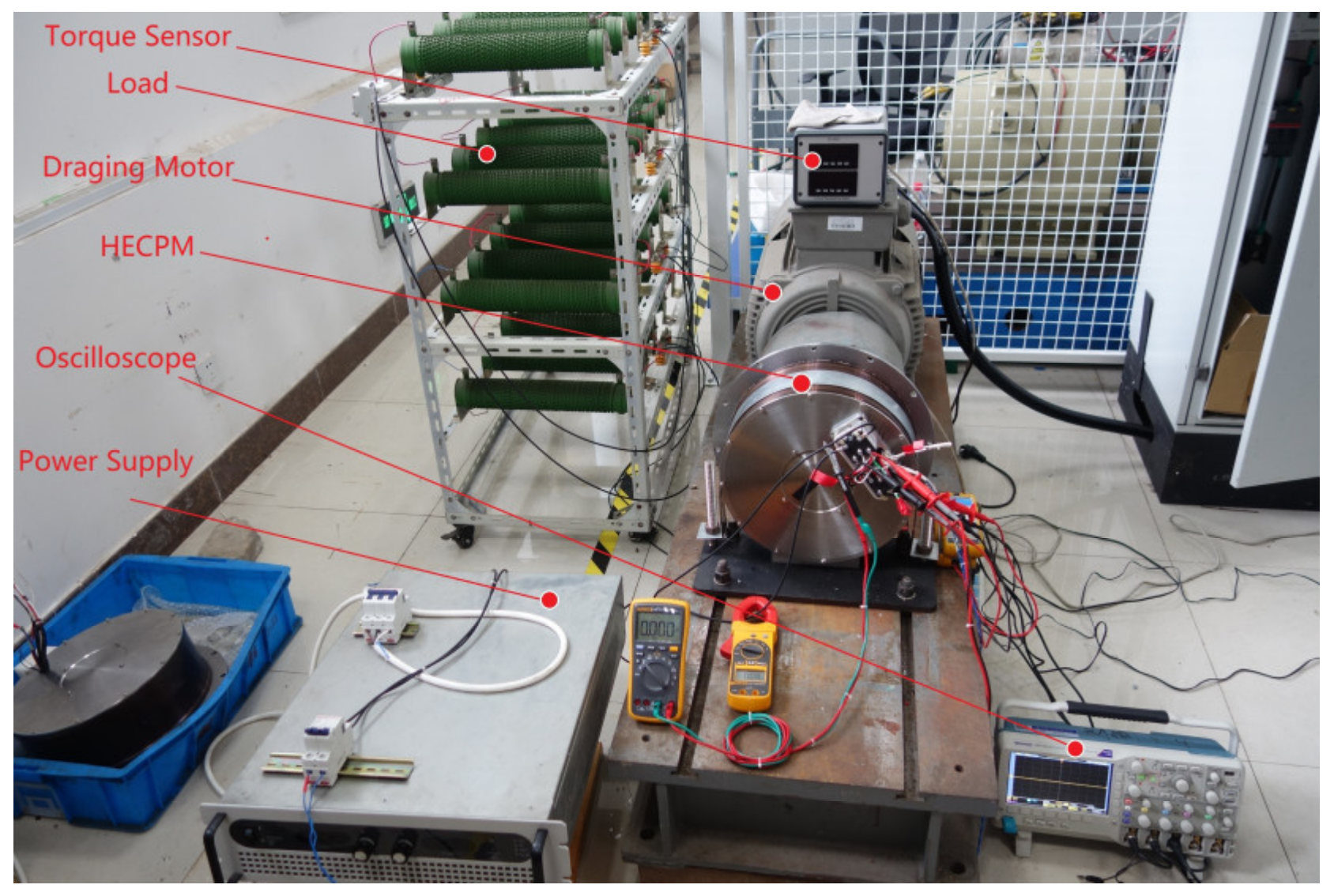
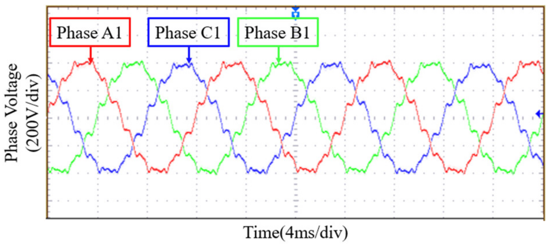
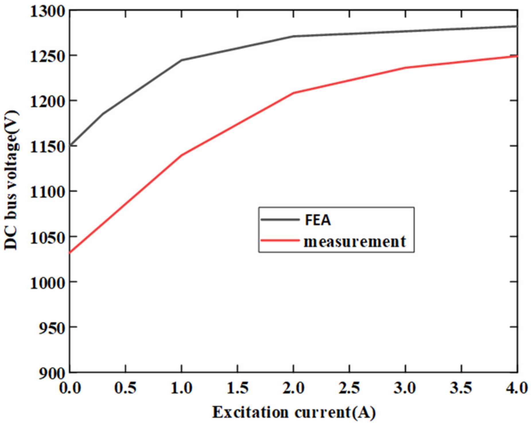
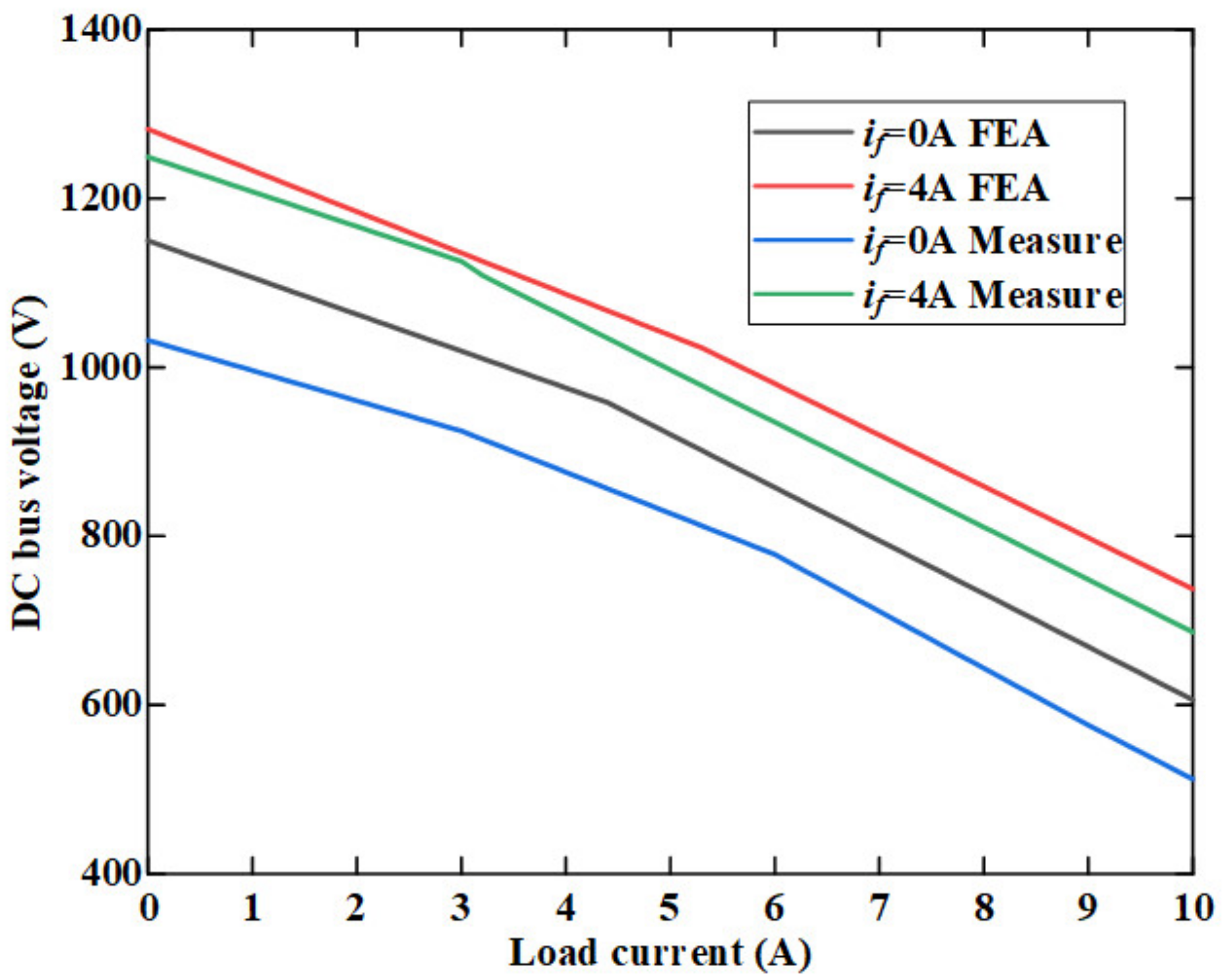
6. Experimental Validation

The prototype of the proposed HE-CPM was manufactured and shown in Figure 21a,b, and its dimension parameters are listed in Table 7. The experimental test bench is shown in Figure 22. A torque sensor is used to measure the electromagnetic torque, and the oscilloscope is used to display the measured waveforms.
The experimental back EMF waveform of the proposed HE-CPM is shown in Figure 23 and it is nearly sinusoidal. It can be seen from Figure 24, with the increase of excitation current, the DC bus voltage also increases. When the excitation current is 4 A, the curve of DC bus voltage becomes flat, and the DC bus voltage is stable at about 1250 V. It can be seen from Figure 25 the DC bus voltage decreases with the increase of load current. When the excitation current changes from 0 A to 4 A, the DC bus voltage increases by about 135 V. Obviously, increasing the excitation current can increase the voltage and also the output power. The experimental results are basically consistent with the FEA results. When the excitation current is 4 A, the rated torque under rated speed (3000 rpm) can be measured by the torque sensor and its value is 32.72 Nm. The rated power can be calculated by (26), and its value is 10.28 kW. The rated voltage under rated speed (3000 rpm) is measured and its value is 543.1 V. The rated parameters of HE-CPM are listed in Table 8.

7. Discussion

It can be seen from Figure 17, Figure 18 and Figure 19 that the field winding which is located in the axial magnetic bridge has the highest temperature. The high temperature also leads to the increase of copper loss and the decrease in efficiency. Therefore, we can consider adding a cooling device in the axial magnetic bridge to reduce the temperature. According to (24), we can use the copper wire of a larger cross-sectional area. Alternatively, we can choose a material with lower resistivity than the wire, such as silver. The resistivity of silver is 1.65 × 10⁻⁸ Ωm. However, silver is too expensive.
Based on the experimental results, the performance of HE-CPM is compared with other similar designs, as shown in Table 9.
The rated power of the proposed HE-CPM is 10.28 kW, and it has the largest power of these machines. The efficiency of the proposed HE-CPM reaches 89%. The claw pole generator reported in [11] has a rated power of 7.2 kW and an efficiency of 92%. However, one issue of this design is the complex stator structure, which leads to difficultly in manufacturing. The hybrid excited claw pole machine reported in [17] has a configuration similar to the proposed HE-CPM, its PMs are mounted on the rotor, and the field winding is embedded within machine shields. However, its rated power is too low due to a small machine size. The claw pole electric machine reported in [25] has an efficiency of 81%, but its rated power is unknown. The relatively large cogging torque in this design is a significant problem. The hybrid excitation claw pole generator reported in [26] has a rated power of 0.65 kW, while its efficiency is unknown. The rated power is too low to be used in large EVs. The hybrid excitation claw pole machine reported in [27] has a decent performance. It has the same rated speed (3000 rpm) as the proposed HE-CPM and the rated power is 5 kW. The usage of an iron powder core in that claw pole machine decreases the torque by about 4% but also reduces the iron losses. It should be noted that the iron powder core is more porous than solid iron. Therefore, the allowable stress of the iron powder core is 125 MPa. The allowable stress of the rotor yoke in the proposed HE-CPM is 800 MPa, which is much higher. Comparing the rated power, voltage, speed and efficiency of these machines, the proposed HE-CPM has the highest rated power (10.28 kW), and the efficiency is about 89%, slightly lower than that of the machine reported in [11].
Because the flux path of the proposed HE-CPM is 3D, we use the combination of PSO and 3D MEC to optimize the dimension parameters of HE-CPM. This optimization method can also be extended to other machines with complex flux paths, such as transverse flux machines.
The main content of this article is optimization design and performance evaluation. The control strategy of HE-CPM will be studied in future work.

8. Conclusions

This article proposes a new kind of HE-CPM which is used in EV. The magnetic field was mainly obtained by PM, and the field excitation coils played the role of adjusting the magnetic field. Firstly, the machine configuration and hybrid flux path were introduced. Then, the 3D MEC method which is related to rotor position was illustrated in detail and the effectiveness was verified by comparing it with the results of FEA. Then, in the design stage, the parameters related to machine performance (torque, torque ripple and loss) were selected, and their sensitivities were analyzed. These main dimension parameters were optimized by using PSO and 3D MEC. The FEA results before and after optimization were compared to verify the effectiveness of machine optimization using the combination of PSO and 3D MEC. The average torque increased to 28.3 Nm and the torque ripple was suppressed. Finally, the machine performance was evaluated, including flux density distribution, electromagnetic characteristics, loss and efficiency, temperature field and mechanical stress. The proposed HE-CPM has a rated power of 10.28 kW, and an efficiency of 89%.
The HE-CPM prototype was manufactured, and a fundamental experiment was conducted. The performance of the proposed HE-CPM was evaluated and the design requirements were met. A good agreement between the FEA and experiment results proved the validity of machine optimization by using PSO and 3D MEC. The combination of PSO and 3D MEC can obtain accurate results and reduce optimization time. This optimization method can be extended to other machines with complex flux paths.

Author Contributions

Conceptualization, Y.C. and C.L.; methodology, Y.C.; software, Y.C. and S.Z.; validation, Y.C., S.Z. and J.Y.; formal analysis, Y.C.; investigation, C.L.; resources, C.L.; data curation, S.Z.; writing—original draft preparation, Y.C.; writing—review and editing, C.L.; visualization, Y.C.; supervision, C.L.; project administration, C.L.; funding acquisition, C.L. All authors have read and agreed to the published version of the manuscript.

Funding

This research was funded by the National Natural Science Foundation of China, grant number 51877108.

Institutional Review Board Statement

Not applicable.

Informed Consent Statement

Not applicable.

Conflicts of Interest

The authors declare no conflict of interest.

References

  1. Zhu, Z.Q.; Cai, S. Overview of Hybrid Excited Machines for Electric Vehicles. In Proceedings of the Fourteenth International Conference on Ecological Vehicles and Renewable Energies (EVER), Monte Carlo, Monaco, 9–10 May 2019; pp. 1–14. [Google Scholar]
  2. Wardach, M.; Palka, R.; Paplicki, P.; Prajzendanc, P.; Zarebski, T. Modern Hybrid Excited Electric Machines. Energies 2020, 13, 5910. [Google Scholar] [CrossRef]
  3. Li, Y.; Yu, Z.; Meng, H.; Wang, J.; Jing, Y. Design and Optimization of Hybrid-Excited Claw-Pole Machine for Vehicle. IEEE Trans. Appl. Supercond. 2021, 31, 1–4. [Google Scholar] [CrossRef]
  4. Omri, R.; Ibala, A.; Masmoudi, A. Hybrid Excited Claw-Pole Machines: Comparison between Different Topologies. In Proceedings of the 16th International Multi-Conference on Systems, Signals & Devices (SSD), Istanbul, Turkey, 21–24 March 2019; pp. 423–428. [Google Scholar] [CrossRef]
  5. Liu, C.; Lu, J.; Wang, Y.; Lei, G.; Zhu, J.; Guo, Y. Design Issues for Claw Pole Machines with Soft Magnetic Composite Cores. Energies 2018, 11, 1998. [Google Scholar] [CrossRef] [Green Version]
  6. Liu, Y.; Zhang, Z.; Zhang, X. Design and Optimization of Hybrid Excitation Synchronous Machines with Magnetic Shunting Rotor for Electric Vehicle Traction Applications. IEEE Trans. Ind. Appl. 2017, 53, 5252–5261. [Google Scholar] [CrossRef]
  7. Rebhi, R.; Ibala, A.; Masmoudi, A. Hybrid excited claw pole alternators: Attempt to satisfy the increasing power need on board. In Proceedings of the 17th International Conference on Electrical Machines and Systems (ICEMS), Hangzhou, China, 22–25 October 2014; pp. 3510–3514. [Google Scholar] [CrossRef]
  8. Rebhi, R.; Ibala, A.; Masmoudi, A. MEC-Based Sizing of a Hybrid-Excited Claw Pole Alternator. IEEE Trans. Ind. Appl. 2014, 51, 211–223. [Google Scholar] [CrossRef]
  9. Omri, R.; Ibala, A.; Masmoudi, A. 3D-FEA based-comparison of different topologies of claw-pole alternators with a dual excitation. In Proceedings of the Thirteenth International Conference on Ecological Vehicles and Renewable Energies (EVER), Monte Carlo, Monaco, 10–12 April 2018; pp. 1–6. [Google Scholar] [CrossRef]
  10. Yu, J.; Cao, Y.; Zhu, S.; Liu, C. Comparison Research of Hybrid Excitation Synchronous Generator between Uniform and Nonuniform Rotor Structure. In Proceedings of the IECON 2019-45th Annual Conference of the IEEE Industrial Electronics Society, Lisbon, Portugal, 14–17 October 2019; pp. 951–956. [Google Scholar] [CrossRef]
  11. Zhao, X.; Niu, S.; Ching, T.W. Design and Analysis of a New Brushless Electrically Excited Claw-Pole Generator for Hybrid Electric Vehicle. IEEE Trans. Magn. 2018, 54, 1–5. [Google Scholar] [CrossRef]
  12. Wang, Q.; Niu, S. A Novel DC-Coil-Free Hybrid-Excited Machine with Consequent-Pole PM Rotor. Energies 2018, 11, 700. [Google Scholar] [CrossRef] [Green Version]
  13. Wardach, M. Design of hybrid excited claw pole machine with laminated rotor structure. In Proceedings of the 2018 Innovative Materials and Technologies in Electrical Engineering (i-MITEL), Sulecin, Poland, 18–20 April 2018; pp. 1–4. [Google Scholar]
  14. Zhang, X.; Zhao, X.; Niu, S. A Novel Dual-Structure Parallel Hybrid Excitation Machine for Electric Vehicle Propulsion. Energies 2019, 12, 338. [Google Scholar] [CrossRef] [Green Version]
  15. Geng, H.; Zhang, X.; Zhang, Y.; Hu, W.; Lei, Y.; Xu, X.; Wang, A.; Wang, S.; Shi, L. Development of Brushless Claw Pole Electrical Excitation and Combined Permanent Magnet Hybrid Excitation Generator for Vehicles. Energies 2020, 13, 4723. [Google Scholar] [CrossRef]
  16. Yang, C.; Lin, H.; Guo, J.; Zhu, Z. Design and Analysis of a Novel Hybrid Excitation Synchronous Machine with Asymmetrically Stagger Permanent Magnet. IEEE Trans. Magn. 2008, 44, 4353–4356. [Google Scholar] [CrossRef]
  17. Melcescu, L.M.; Cistelecan, M.V.; Popescu, M.; Craiu, O. Design and development of a hybrid excited claw pole synchronous machine. In Proceedings of the International Aegean Conference on Electrical Machines and Power Electronics and Electromotion, Joint Conference, Istanbul, Turkey, 8–10 September 2011; pp. 799–804. [Google Scholar]
  18. Derbas, H.W.; Williams, J.M.; Koenig, A.C.; Pekarek, S.D. A Comparison of Nodal- and Mesh-Based Magnetic Equivalent Circuit Models. IEEE Trans. Energy Convers. 2009, 24, 388–396. [Google Scholar] [CrossRef] [Green Version]
  19. Elloumi, D.; Ibala, A.; Rebhi, R.; Masmoudi, A. 3D MEC modeling of a hybrid-excited claw pole alternator incorporating the rotor motion. In Proceedings of the 2015 International Conference on Sustainable Mobility Applications, Renewables and Technology (SMART), Kuwait City, Kuwait, 23–25 November 2015; pp. 1–7. [Google Scholar] [CrossRef]
  20. Elloumi, D.; Ibala, A.; Rebhi, R.; Masmoudi, A. Lumped Circuit Accounting for the Rotor Motion Dedicated to the Investigation of the Time-Varying Features of Claw Pole Topologies. IEEE Trans. Magn. 2015, 51, 1–8. [Google Scholar] [CrossRef]
  21. Asfirane, S.; Hlioui, S.; Amara, Y.; Gabsi, M. Study of a Hybrid Excitation Synchronous Machine: Modeling and Experimental Validation. Math. Comput. Appl. 2019, 24, 34. [Google Scholar] [CrossRef] [Green Version]
  22. Lee, J.H.; Kim, J.; Song, J.; Kim, D.; Kim, Y.; Jung, S. Distance-Based Intelligent Particle Swarm Optimization for Optimal Design of Permanent Magnet Synchronous Machine. IEEE Trans. Magn. 2017, 53, 1–4. [Google Scholar] [CrossRef]
  23. Wrobel, R.; Griffo, A.; Mellor, P.H. Scaling of AC copper loss in thermal modeling of electrical machines. In Proceedings of the 2012 XXth International Conference on Electrical Machines, Marseille, France, 2–5 September 2012; pp. 1424–1429. [Google Scholar] [CrossRef]
  24. Ding, H.C.; Xiao, L.J.; Zhang, H.Y.; Sun, C.Y. Interference Fit Calculation and Stress Analysis for Rotor Sleeve of High-speed Permanent Magnet Electric Machine. Mach. Des. Res. 2011. [Google Scholar]
  25. Wardach, M. Hybrid excited claw pole electric machine. In Proceedings of the 21st International Conference on Methods and Models in Automation and Robotics (MMAR), Miedzyzdroje, Poland, 4–5 October 2016; pp. 152–156. [Google Scholar]
  26. Chao-Hui, Z.; Huanqiu, G.; Xin-Wei, W. The Study of Structure and Characteristic of a New Type HECPSG. In Proceedings of the IEEE International Symposium on Industrial Electronics, Vigo, Spain, 4–7 June 2007; pp. 1097–1100. [Google Scholar] [CrossRef]
  27. Hagstedt, D.; Reinap, A.; Ottosson, J.; Alakula, M. Design and experimental evaluation of a compact hybrid excitation claw-pole rotor. In Proceedings of the 2012 XXth International Conference on Electrical Machines, Marseille, France, 2–5 September 2012; pp. 2896–2901. [Google Scholar] [CrossRef]
Figure 1. HE-CPM structure diagram. (a) Front view. (b) Section view. (c) Exploded view.
Processes 10 00541 g001
Figure 2. Hybrid flux path in HE-CPM. (a) PM excitation flux path. (b) Field excitation flux path.
Processes 10 00541 g002
Figure 3. Magnetic equivalent circuit model of HE-CPM under a pair of magnetic poles at initial rotor position.
Processes 10 00541 g003
Figure 4. Different reluctance equivalent shapes. (a) Tile; (b) Vertical plane; (c) Concentric cylinder; (d) Parallel torus.
Processes 10 00541 g004
Figure 5. Flow chart of 3D MEC.
Processes 10 00541 g005
Figure 6. Comparison results of back EMF between FEA and MEC.
Processes 10 00541 g006
Figure 7. HE-CPM parameters definition. (a) Front view. (b) Section view.
Processes 10 00541 g007
Figure 8. The sensitivity of different design variables.
Processes 10 00541 g008
Figure 9. Pareto solution set. (a) Level A. (b) Level B.
Processes 10 00541 g009
Figure 10. FEA results before and after optimization. (a) Torque. (b) Hysteresis loss. (c) Eddy current loss.
Processes 10 00541 g010
Figure 11. No-load flux density distributions of HE-CPM. (a) Front view. (b) Section view.
Processes 10 00541 g011
Figure 12. Magnetic flux density of main air gap under different excitation currents at full load.
Processes 10 00541 g012
Figure 13. No-load back EMF of HE-CPM.
Processes 10 00541 g013
Figure 14. Relationship between bus voltage and excitation current at different speeds.
Processes 10 00541 g014
Figure 15. Relationship between bus voltage and load current at different excitation currents.
Processes 10 00541 g015
Figure 16. Machine efficiency diagram. (a) Relationship between efficiency and load current. (b) Relationship between efficiency and excitation current.
Processes 10 00541 g016
Figure 17. Temperature field nephogram of HE-CPM. (a) Front view. (b) Section view.
Processes 10 00541 g017
Figure 18. Temperature field nephogram of axial magnetic bridges. (a) If = 1 A. (b) If = 2 A. (c) If = 4 A.
Processes 10 00541 g018
Figure 19. Relationship between axial magnetic bridge temperature and excitation current.
Processes 10 00541 g019
Figure 20. Mechanical stress nephogram of HE-CPM. (a) Rotor. (b) Rotor yoke.
Processes 10 00541 g020
Figure 21. Prototype photos. (a) Inside the prototype. (b) Prototype as a whole.
Processes 10 00541 g021
Figure 22. Experimental test bench of the proposed HE-CPM.
Processes 10 00541 g022
Figure 23. Experimental back EMF waveform of the proposed HE-CPM.
Processes 10 00541 g023
Figure 24. Comparison results of DC bus voltage versus excitation current between FEA and experimental measurement.
Processes 10 00541 g024
Figure 25. Comparison results of DC bus voltage versus load current between FEA and experimental measurement.
Processes 10 00541 g025
Table 1. Different items in MEC.
ItemSymbol
Equivalent reluctance of stator yoke R S Z 1 ,   R S Z 2 ,   R S Z 3
Equivalent reluctance of stator tooth R S T 1 ,   R S T 2
Equivalent reluctance of stator shoe R S P 1 ~ R S P 4
Equivalent reluctance of rotor yoke R R Z 1 ~ R R Z 6
Equivalent reluctance of axial magnetic bridge R R Z σ 1 ,   R R Z σ 2 ,   R R Z σ 3
Equivalent reluctance of claw-pole rotor finger R R T 1 ~ R R T 6
Equivalent reluctance of enclosure R C
Equivalent reluctance of front and back ending cover R D 1 ~ R D 6
Equivalent reluctance of claw-pole rotor finger yoke R R V 1 ,   R R V 2
PM equivalent internal reluctance R P M 1 ,   R P M 2 ,   R P M 3
Main air gap reluctance R δ 1 ~ R δ 5
Auxiliary air gap reluctance R δ F 1 ,   R δ F 2
Flux leakage reluctance in stator slot R S S σ
Flux leakage reluctance between adjacent stator shoes R S P σ
Phase A armature reactive MMF F A
PM equivalent MMF source F P M 1 ,   F P M 2 ,   F P M 3
Field excitation equivalent MMF source F E 1 ,   F E 2
Table 2. Dimension parameters of HE-CPM.
ParameterValueParameterValue
PM widthwPMMain air gap thicknessgmain
Stator notch widthwnotAuxiliary air gap thicknessgaux
Stator tooth widthwstStator lengthlst
PM thicknessdPMEnclosure lengthlen
Rotor yoke thicknessdryRotor lengthlrot
Stator tooth heightdstEnding cover lengthlec
Nonmagnetic ring thicknessdnoAxial magnetic bridge lengthlamb
Table 3. Design variables and their sensitivity.
Design Variable S t S t r S l S i
wPM0.716−0.0540.5370.512
wnot−0.533−0.41−0.4510.4174
wst0.1340.4090.1270.1862
dPM0.2260.0370.30.2178
dry−0.0910.096−0.3930.2128
dst−0.0040.0740.0280.0276
gmain0.249−0.1190.250.2234
Table 4. Optimization results of design variables.
Design VariableInitial ValueOptimized Value
wPM2223.1
wnot2628.6
gmain10.6
dPM3.24.4
dry66.4
Table 5. Torque ripple.
Before OptimizationAfter Optimization
Maximum value29.8 Nm31.5 Nm
Minimum value22.4 Nm25.1 Nm
Average value26.1 Nm28.3 Nm
Torque ripple28.4%22.6%
Table 6. Material parameters of rotor yoke.
Elastic Modulus
E / P a
Density
ρ / kg · m 3
Poisson’s Ratio
v
Allowable Stress
σ / M P a
2.06 × 101178500.31800
Table 7. Dimension parameters of HE-CPM prototype.
ParametersValue
Stator outer diameter312 mm
Stator inner diameter200 mm
Effective core length52 mm
Rotor outer diameter198.8 mm
Rotor inner diameter120 mm
Winding factor0.966
Number of slots12
Stacking factor0.9
Armature winding turns210
Stator yoke width17 mm
Stator tooth width28.28 mm
PM length53 mm
Table 8. Rated parameters of HE-CPM.
Rated PowerRated TorqueRated VoltageRated Speed
10.28 kW32.72 Nm543.1 V3000 rpm
Table 9. Performances comparison.
Proposed HE-CPMElectrically
Excited Claw Pole Generator Reported in [11]
Hybrid Excited Claw Pole
Synchronous
Machine Reported in [17]
Hybrid Excited Claw Pole
Electric
Machine
Reported in [25]
Hybrid
Excitation Claw Pole
Synchronous Generator
Reported in [26]
Hybrid
Excitation Claw Pole
Machine
Reported in [27]
Rated power10.28 kW7.2 kW0.73 kW-0.65 kW5 kW
Rated voltage543.1 V48 V120 V14 V135.5 V108 V
Rated speed3000 rpm900 rpm1200 rpm1300 rpm1500 rpm3000 rpm
Efficiency89%92%-81%--
Publisher’s Note: MDPI stays neutral with regard to jurisdictional claims in published maps and institutional affiliations.

