
Study on Properties of High-Vanadium Full-Locked Cable with Alloy Coating with Defects


Abstract
:1. Introduction
2. Experimental
2.1. Design and Manufacture of Specimen
2.2. Experimental Materials and Instruments
2.3. Experiment for Accelerated Corrosion
- (1)
- The HVFLC is subject to corrosion from atmospheric conditions during application. Accelerated corrosion test can simulate the effect of long-period atmospheric corrosion in the laboratory. According to GBT 6455-2008 [6], the corrosion paste experiment is used to simulate the accelerated corrosion test.
- (2)
- Preparation of corrosion paste. 0.035 g of Cu (NO3)2·3H2O (AR), 0.165 g of FeCl3-6H2O (AR) and 1.0 g of NH4Cl (AR) were dissolved in 50.0 mL of distilled water. Then, 30.0 g of kaolinite was added. In order to fully soak the kaolin, the slurry was mixed thoroughly by rapid stirring with a glass rod and allowed to stand for 2 min. Stir well with a glass rod before using.
- (3)
- Brushing of corrosion paste. Apply the corrosion paste evenly on the specimen. The thickness of the corrosion paste should be between 0.08 mm and 0.20 mm. The specimen is dried at room temperature with relative humidity less than 50% for 1 h, and then placed in a humid room.
- (4)
- Setting the corrosive environment. The treated specimens are reasonably placed in a damp box. There is no contact between the specimen and the specimen or between the specimen and the wall of the box. The temperature in the test chamber is maintained at 35 ± 1 °C, and the relative humidity is maintained between 80~90%.
- (5)
- Test period and specimen treatment after testing. Every 24 h is an experimental period. After the test, the specimen is cleaned to remove the corrosion paste from the surface.
2.4. Characterization and Performance Testing
3. Results and Discussions
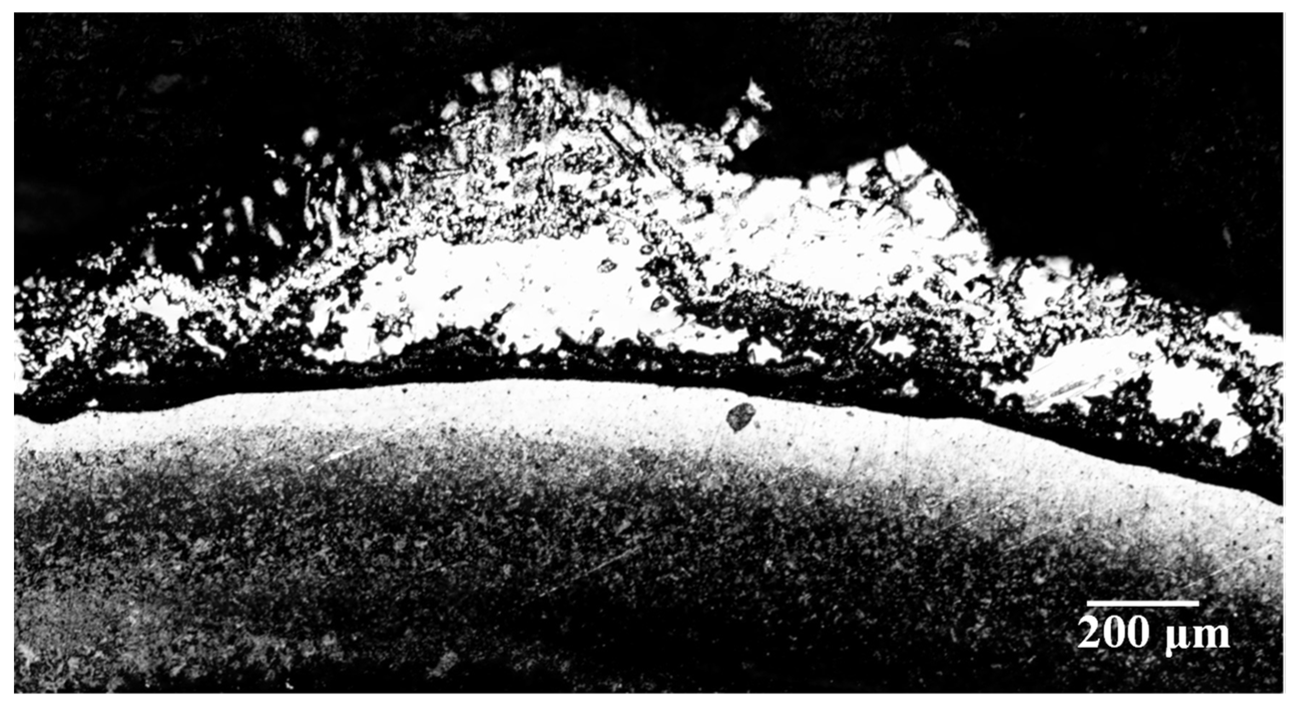
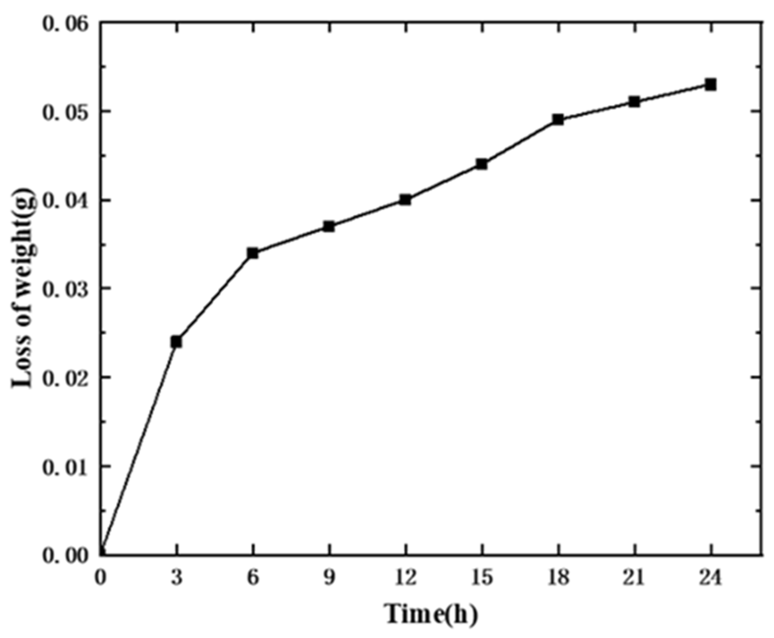
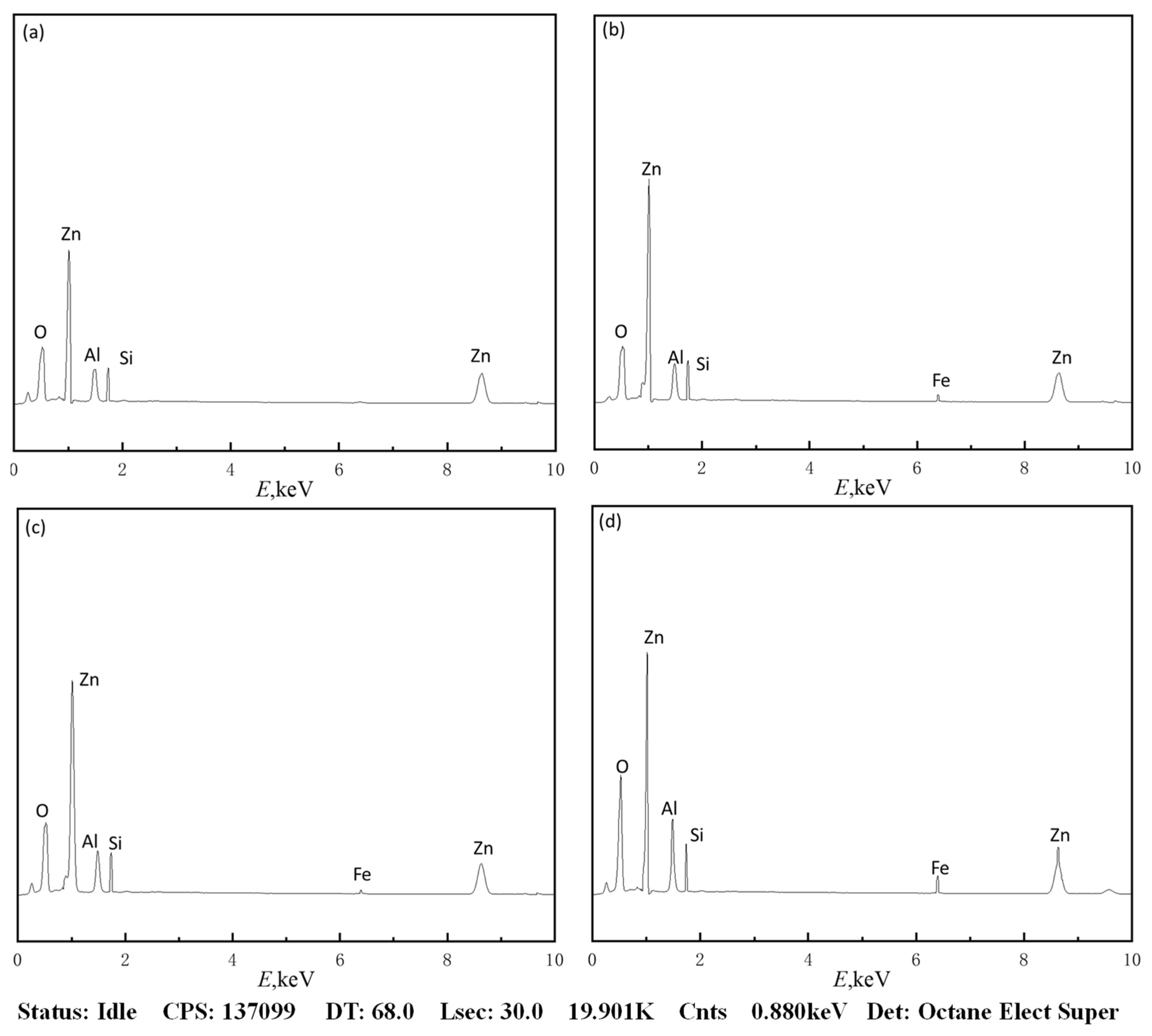
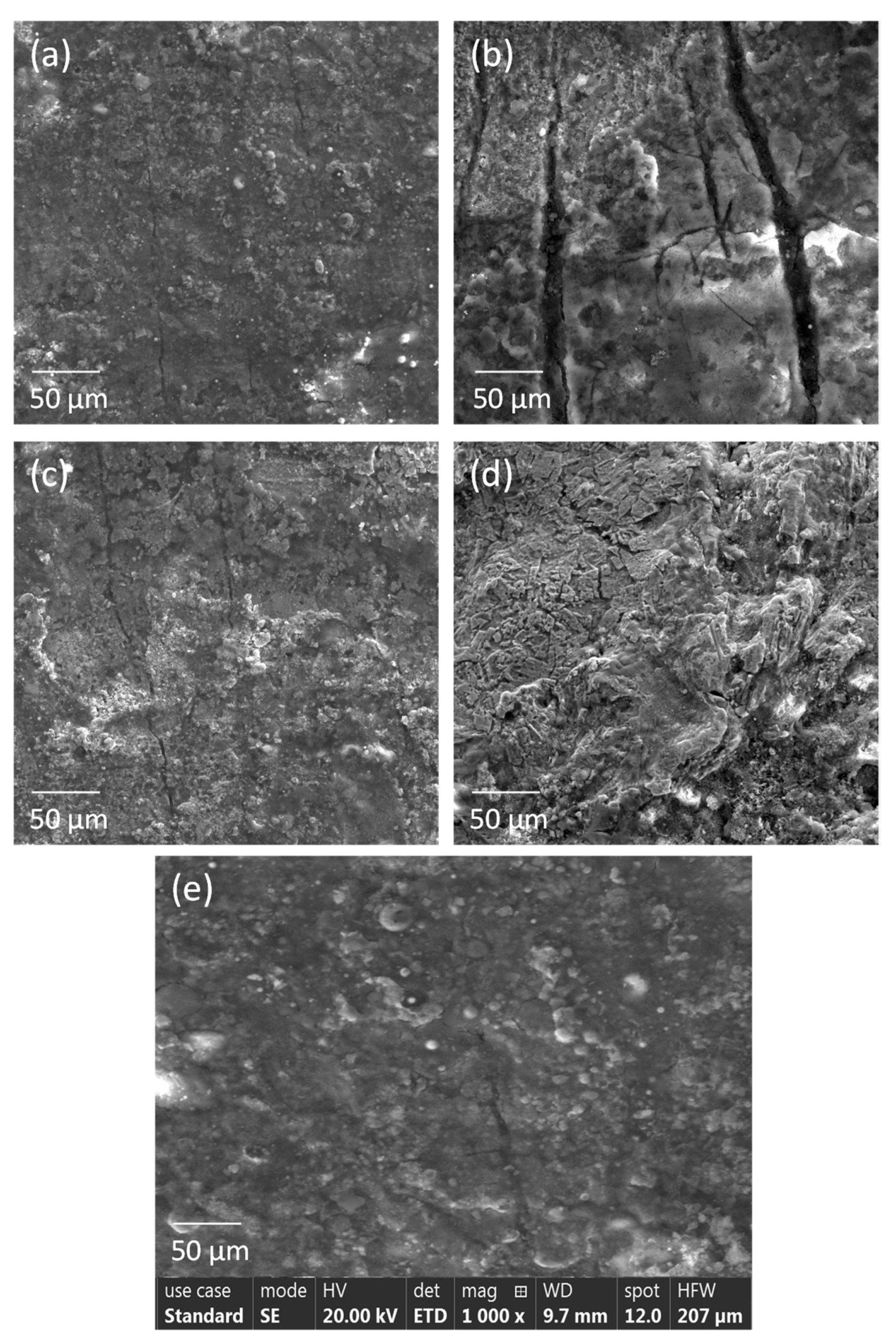
3.1. Research on Corrosion Regularity
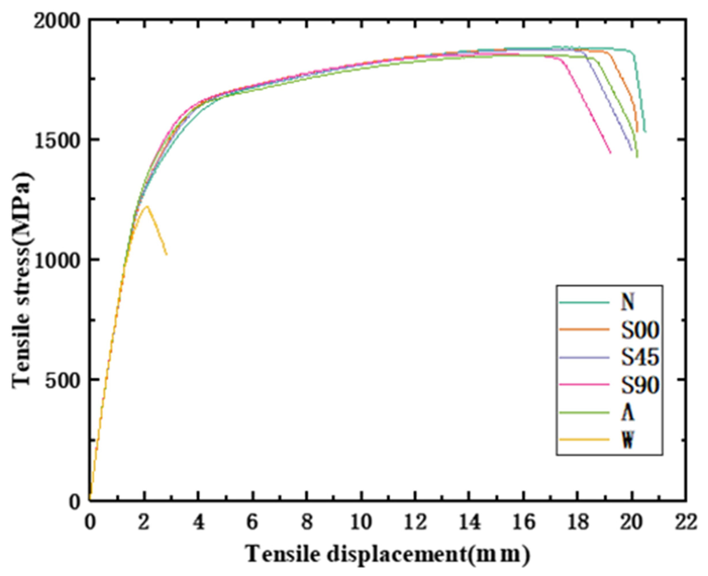
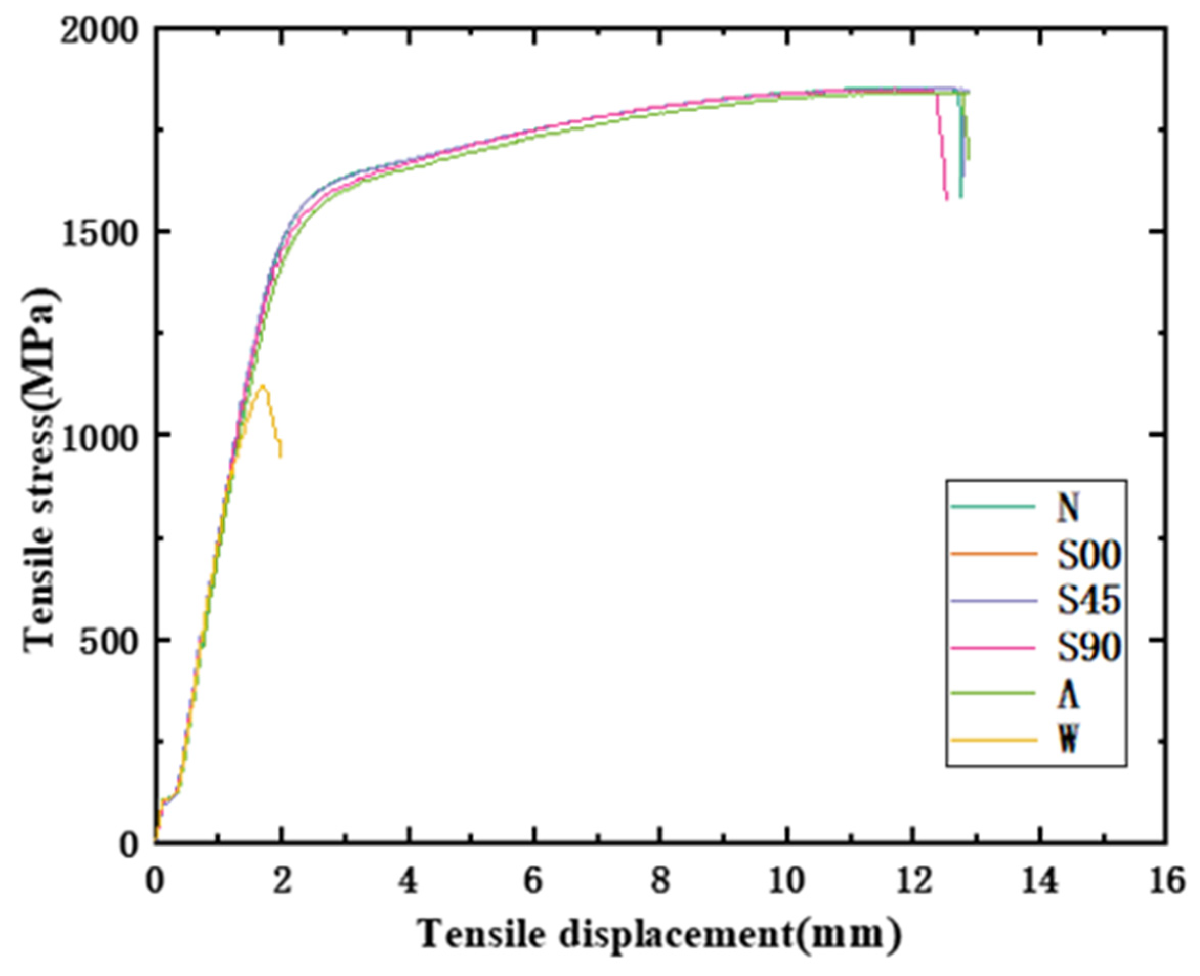
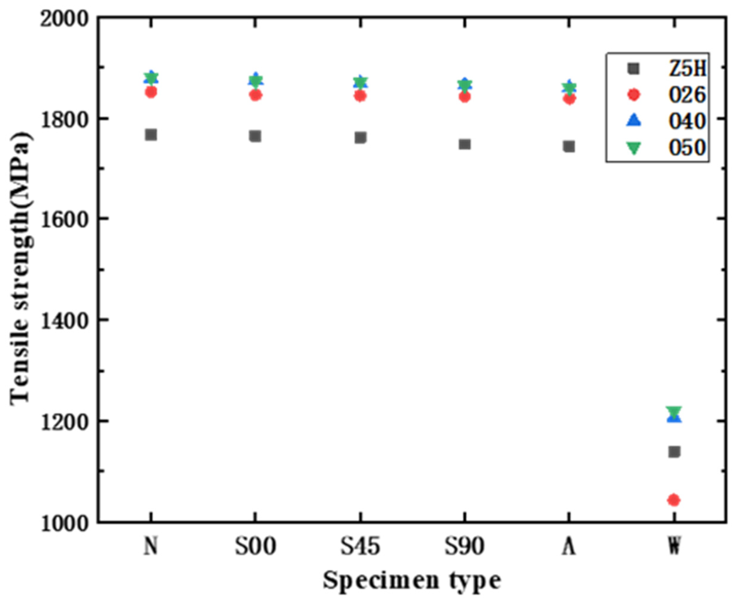
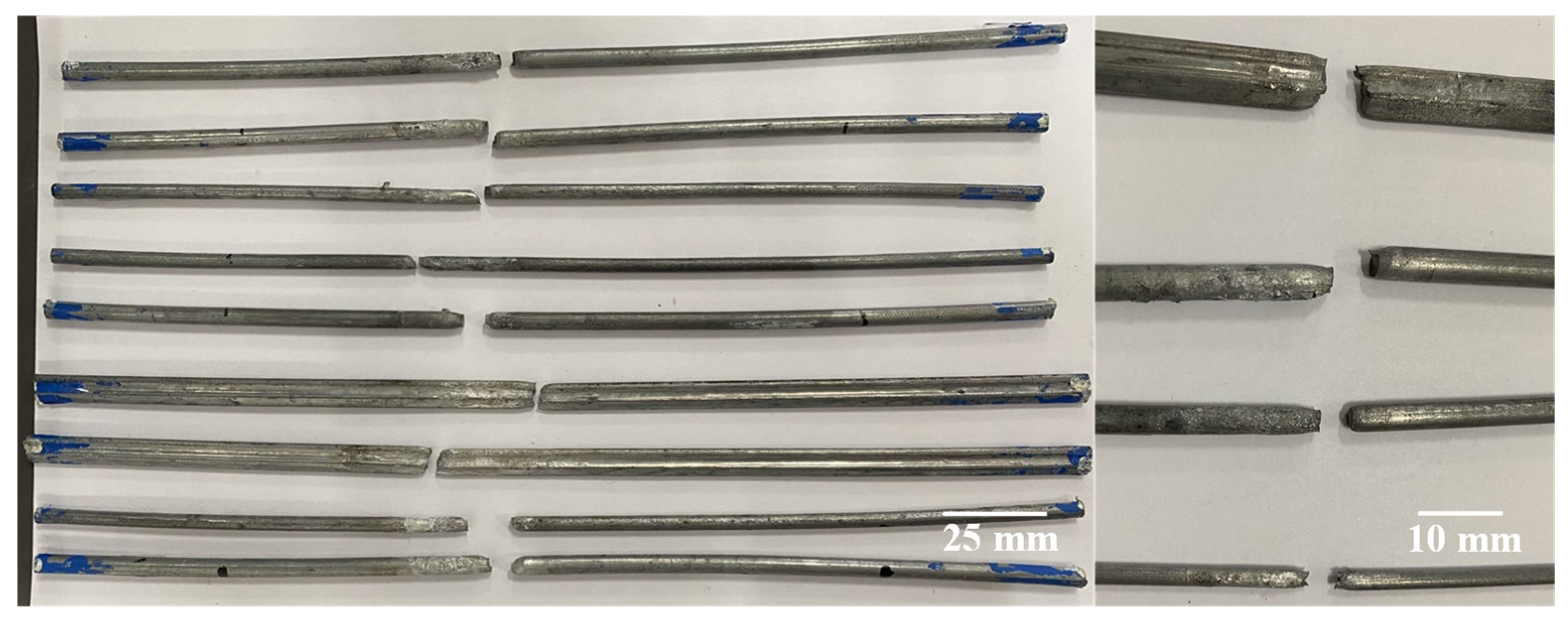
3.2. Characterization of Mechanical Properties
4. Conclusions
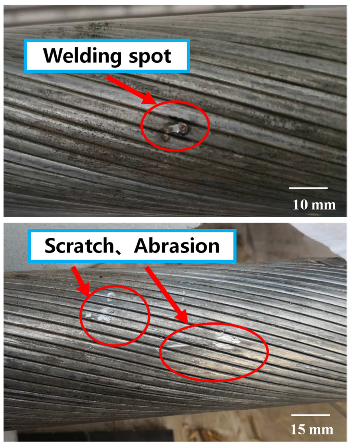
- (1)
- Defects of scratches, abrasions and welding spots inevitably occur during processing and installation of the HVFLC. Defects can damage the Zn-5%Al-rare earth alloy coating on the surface of the wires. It will negatively affect the mechanical properties and corrosion resistance of the HVFLC, and adversely affect the long-term service performance.
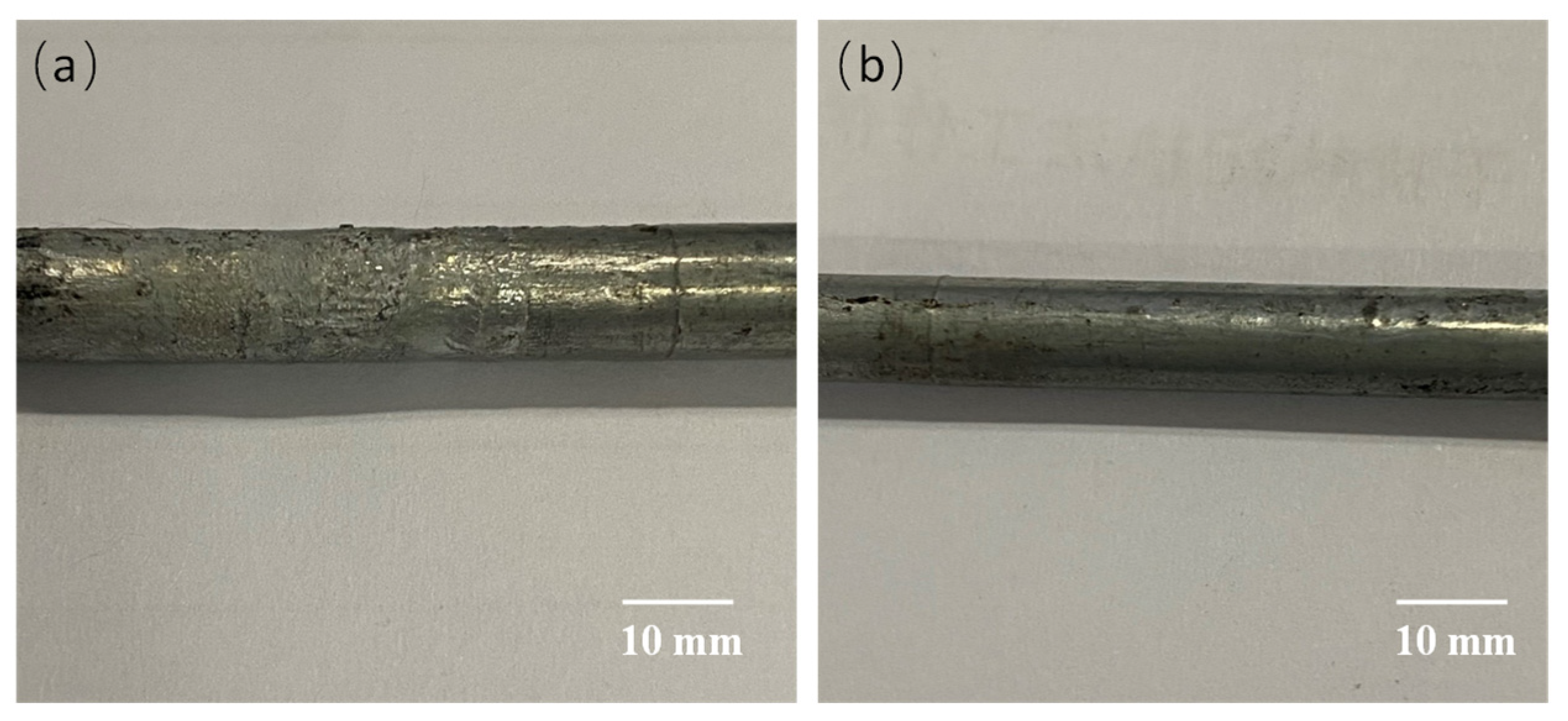
- (2)
- The accelerated corrosion tests with corrosion paste showed that the presence of scratch, abrasion and welding spot damaged the Zn-5% Al-rare earth alloy coating on the surface of the HVFLC. Different effects on the corrosion resistance of the wires were observed. The effect of welding spot defects is the most serious, and the corrosion mechanism and pattern still need further study.
- (3)
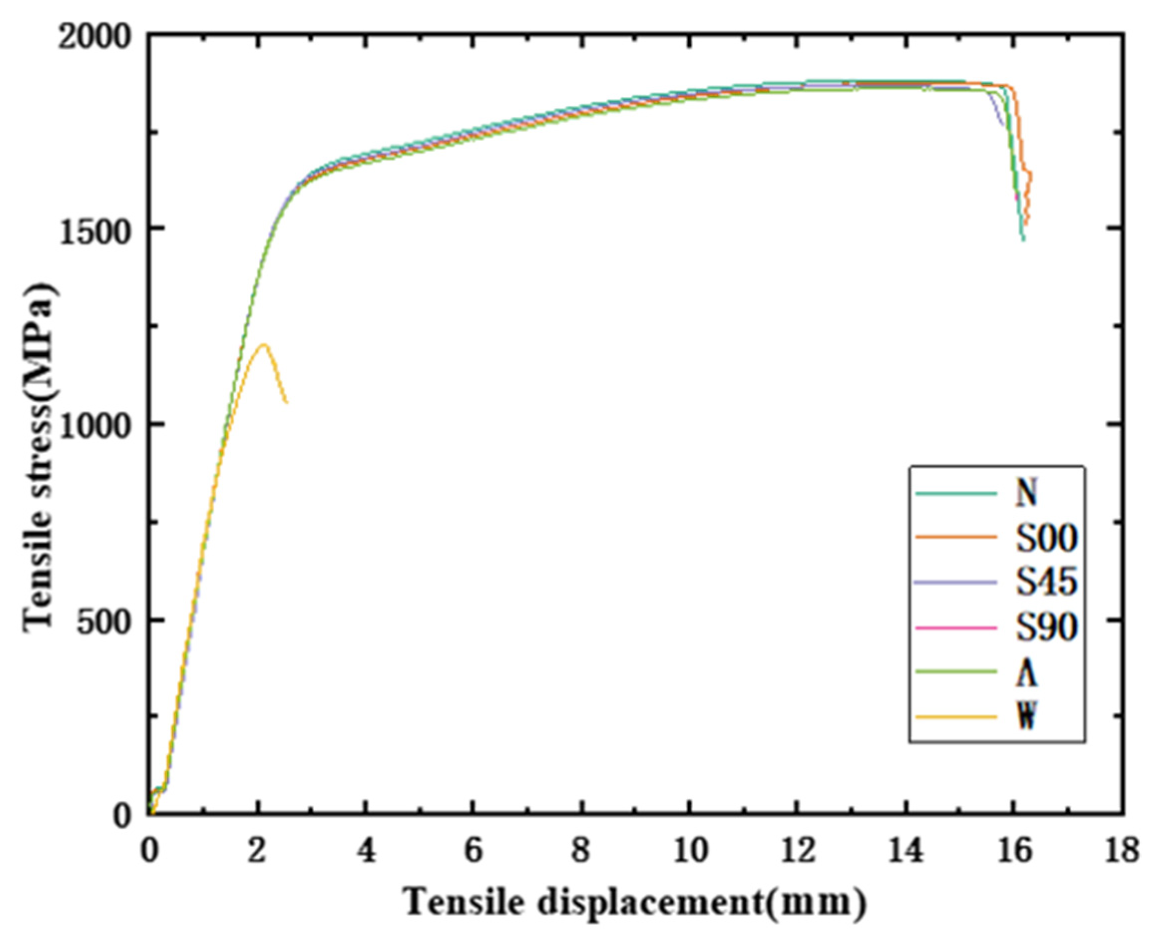
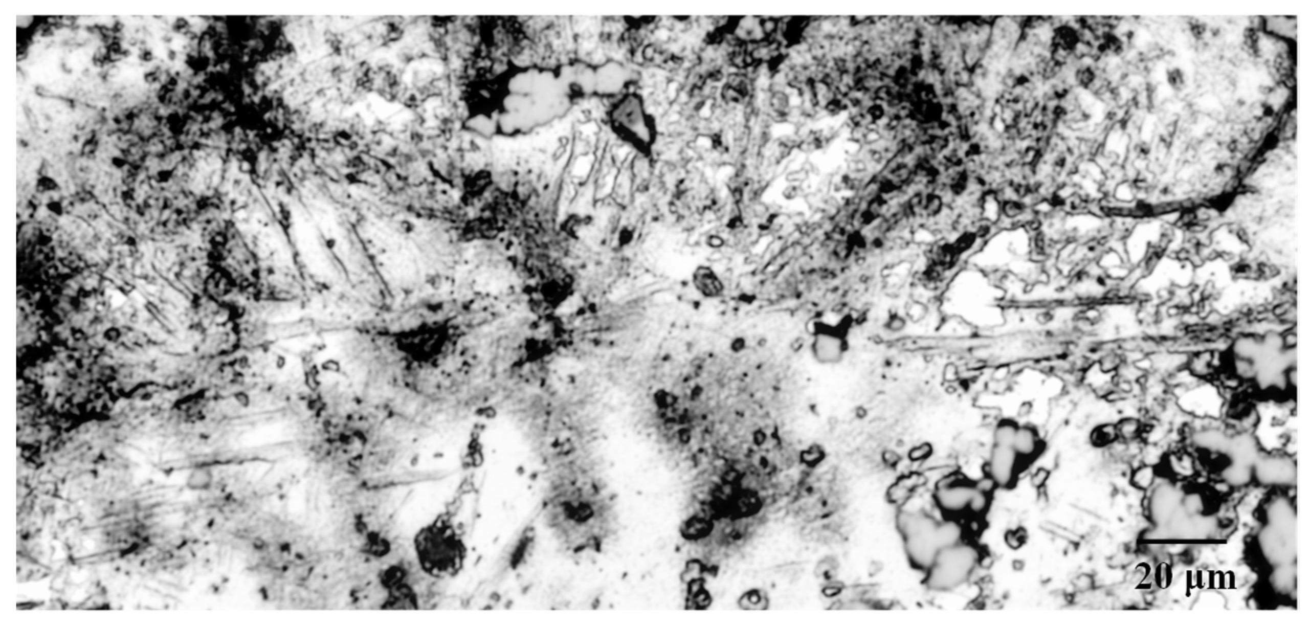
- It can be found from the mechanical tensile test that the mechanical properties of the HVFLC were affected by various defects. Stress concentration occurs during tension due to surface defects of specimens. Defected specimens are more likely to fail under tension than standard specimens with a complete alloy coating. In addition, the presence of welding spot defects changed the metallographic structural characteristics of the specimens. A hard brittle martensite structure with poor toughness was produced in these areas. The mixed fractures of brittle fractures and ductile fractures occur in the specimens. Additionally, the tensile strength of the specimens decreases by about 40%.
- (4)
- Defects causing damage to alloy coating should be avoided as far as possible during processing and application of the HVFLC. Defects of welding spots have a great influence on corrosion resistance and mechanical properties. In order to guarantee the long-term service performance of the cable body, it is necessary to prevent the occurrence of welding spots.
Author Contributions
Funding
Data Availability Statement
Acknowledgments
Conflicts of Interest
References
- Yang, Y.C.; Chen, B.L. Design of main structure of national speed skating Hall. Build. Struct. 2018, 48, 1–4. [Google Scholar]
- Wang, Z.; Bai, G.B. Steel structural design of National Speed Skating Oval. Build. Struct. 2018, 48, 5–11. [Google Scholar]
- Zhang, J.X.; Gao, S.D.; Wang, Z.Q. Key Construction Technology of Long-span Saddleback Cable Network Structure of National Speed Skating Oval. Constr. Technol. 2019, 48, 41–44. [Google Scholar]
- Bai, G.B.; Wang, Z. Key Issues in Cable Net Form-Finding of the National Speed Skating Oval. Steel Constr. 2020, 35, 54–61. [Google Scholar]
- Zhang, Y.; Su, Z.H. Manufacture Technologies of High-Vanadium Full-Locked Cable Used in National Speed Skating Oval Project. Constr. Technol. 2020, 49, 7–11. [Google Scholar]
- GB/T 6465-2008; Metallic and Other Non-Organic Coatings-Corrodkote Corrosion Test (CORR Test). Standard GB: Beijing, China, 2008.
- Wang, X.F.; Liu, H. Effect of welding method on defect, microstructure and mechanical properties of welded joints of Q235 steel. Trans. Mater. Heat Treat. 2021, 42, 150–159. [Google Scholar]
- Chen, L.; Nie, P.; Qu, Z.; Ojo, O.A.; Xia, L.; Li, Z.; Huang, J. Influence of heat input on the changes in the microstructure and fracture behavior of laser welded 800MPa grade high-strength low-alloy steel. J. Manuf. Processes 2020, 50, 132–141. [Google Scholar] [CrossRef]
- Song, S.K.; Feng, Y. Correlativity on corrodkote accelerated corrosion test and atmospheric exposure test of pure aluminum 1060. Light Met. 2018, 2, 54–58. [Google Scholar]
- Han, G.M. Theory and Technology of Welding Process; China Machine Press: Beijing, China, 2018. [Google Scholar]
- Li, Y.J.; Wang, J. Welding Defect Analysis and Countermeasures; Chemical Industry Press: Beijing, China, 2018. [Google Scholar]
- Bai, L.Y.; Jiang, K.B.; Gao, L. The Influence and Mechanism of Residual Stress on the Corrosion Behavior of Welded Structures. Mater. Res. 2018, 21, e20180166. [Google Scholar] [CrossRef] [Green Version]


| Section | Diameter | Defects | Serial Number |
|---|---|---|---|
| Z | 5H | N/A/S00/S45/S90/W | 1/2/3/4/5/6 |
| O | 26 | N/A/S00/S45/S90/W | 1/2/3/4/5/6 |
| O | 40 | N/A/S00/S45/S90/W | 1/2/3/4/5/6 |
| O | 50 | N/A/S00/S45/S90/W | 1/2/3/4/5/6 |
| Name | Specification | Manufactor |
|---|---|---|
| Cu(NO3)2·3H2O | AR 99.9% | Macklin |
| FeCl3·6H2O | AR 99% | Macklin |
| NH4Cl | AR 99.9% | Macklin |
| Kaolin | CP | Macklin |
| Ethanol absolute | AR 99.7% | Macklin |
| Deionized water | / | / |
Publisher’s Note: MDPI stays neutral with regard to jurisdictional claims in published maps and institutional affiliations. |
© 2022 by the authors. Licensee MDPI, Basel, Switzerland. This article is an open access article distributed under the terms and conditions of the Creative Commons Attribution (CC BY) license (https://creativecommons.org/licenses/by/4.0/).
Share and Cite
Fang, Z.; Fu, J.; Wang, Z.; Chen, B.; Shi, P.; Ma, J. Study on Properties of High-Vanadium Full-Locked Cable with Alloy Coating with Defects. Processes 2022, 10, 513. https://doi.org/10.3390/pr10030513
Fang Z, Fu J, Wang Z, Chen B, Shi P, Ma J. Study on Properties of High-Vanadium Full-Locked Cable with Alloy Coating with Defects. Processes. 2022; 10(3):513. https://doi.org/10.3390/pr10030513
Chicago/Turabian StyleFang, Zhou, Junjie Fu, Zhe Wang, Binlei Chen, Puan Shi, and Jiahao Ma. 2022. "Study on Properties of High-Vanadium Full-Locked Cable with Alloy Coating with Defects" Processes 10, no. 3: 513. https://doi.org/10.3390/pr10030513
APA StyleFang, Z., Fu, J., Wang, Z., Chen, B., Shi, P., & Ma, J. (2022). Study on Properties of High-Vanadium Full-Locked Cable with Alloy Coating with Defects. Processes, 10(3), 513. https://doi.org/10.3390/pr10030513