Article

Behavior of Top-Blown Jet under a New Cyclone Oxygen Lance during BOF Steelmaking Process

State Key Laboratory of Advanced Special Steel, Shanghai Key Laboratory of Advanced Ferrometallurgy, School of Materials Science and Engineering, Shanghai University, Shanghai 200444, China
*
Author to whom correspondence should be addressed.
Processes 2022, 10(3), 507; https://doi.org/10.3390/pr10030507
Submission received: 12 January 2022 / Revised: 4 February 2022 / Accepted: 23 February 2022 / Published: 3 March 2022
(This article belongs to the Special Issue Computational Modeling of Multiphase Flow (II))

Abstract

:
An oxygen lance is the operation unit that generates supersonic oxygen jets, controls their behavior, and acts as a vital role in the steelmaking process. It is thought that airflow similar to a tornado may suppress upward splashing because of part of the jet pressure shifting from the axis of the oxygen lance to the tangential direction. Therefore, a new oxygen lance is designed to form a tornado jet, and the numerical simulation consequences are verified by the physical model. The structure of the new oxygen lance is optimized by numerical simulation results, and the comparison of simulation results before and after optimization is analyzed. On this basis, the effect of the cyclone oxygen lance on the upward splashing behavior, penetrating depth, turbulent kinetic energy, turbulent dissipation rate, and rotation of molten bath is investigated. The conclusions present that, compared with the conventional oxygen lance, the upward splashing with the cyclone oxygen lance decreases, and the penetrating depth and reaction area increase. In other words, for obtaining the same penetrating depth, the cyclone lance height can be higher than that of a conventional oxygen lance, which leads to a better protective effect on the refractories of the oxygen lance. Moreover, the average value of the turbulent kinetic energy of the cyclone nozzle is larger than that of the traditional Laval nozzle at the interface between oxygen and slag, which improves the effect of steelmaking.

1. Introduction

During the steelmaking process, the decarbonization reaction between oxygen and molten steel happens through a gas jet formed by the top lance. A supersonic oxygen lance has been applied in a converter effectively, and a lot of good effects have been reached. However, the upward splashing of the steelmaking process caused by the supersonic oxygen lance will lower productivity and metal recovery [1]. Splashing will also seriously cause the loss of the lining and damage to the oxygen lance [2,3]. Moreover, the jet coalescence of traditional oxygen lance weakens the effect of the single jets because the jets swallow a lot of the surrounding medium. We think that if airflow similar to a tornado can be obtained, the splashing behavior in the converter may be restrained because of part of the jet pressure shifting from the axis of the oxygen lance to the tangential direction. So, a new cyclone oxygen lance is designed to solve the problems mentioned above. The effect of the cyclone nozzle on the upward splashing behavior, penetrating depth, and reaction area of molten bath compared with a traditional oxygen lance were investigated for the purpose of proposing scientific theoretical basis for the lance design and the practical application of the cyclone oxygen lance.
Some scholars have studied the influence of nozzle arrangement on the molten bath [4,5,6]. Some scholars have researched the influence of new designed nozzle on the molten bath [7,8]. Some scholars have researched the influence of temperature on the molten bath [9,10]. The research group of Davood Toghraie did a lot of studies in multiphase flow field [11,12,13,14,15,16]. Liu et al. analyzed the mixing capacity and flow field of conventional and new twisted oxygen lances (twist angles are 4°, 8°, and 12°, respectively) on the molten bath [17]. Sambasivam et al. proposed a new subsonic nozzle placed in the center of the lance in order to control flow [18]. The blowing performance of the lance was studied by numerical simulation and water modeling. The new oxygen lance can significantly improve the droplet generation rate. Qiang Li et al. considered that the operation pressure and lance height have more considerable effects on the interface behavior, cavity depth, and hydrodynamics in the molten bath than viscosity and surface tension [19]. Naji Meidani et al. proposed a new supersonic oxygen lance and studied the depth of penetration and mixing times of the jet formed by the new lance [20]. They considered that jet penetration depth was decided by gas flow rate, lance height, and bath density. Cao et al. researched the mixing behavior of the 80t converter by physical model and numerical simulation [21]. They put forward the cavity shape index and considered that the depth and width of the cavity should be limited nearly equally. Ming Lv and Rong Zhu analyzed the flow field and radius of traditional oxygen jet and coherent jet and studied the influence of annular gas flow rate on the central jet velocity [22]. The conclusion showed that the supersonic region of the jet increases with increasing annular gas flow rate. Mingming Li et al. researched the coherent behavior of supersonic oxygen jets by the Laval oxygen lance simulation [23]. The conclusion showed that the high surrounding temperature prolongs the supersonic region of the jet. Norifumi Asahara et al. investigated the cavity formation and spitting phenomena with individual and multi hole nozzles [24]. Cao et al. put forward a literature review on latest progress in the steelmaking process [25]. In addition, there are a few studies that have been put forward to investigate the effect of lance construction on the jet flow field and the molten bath.
The article presents a novel lance design to improve the blowing performance. A cyclone oxygen lance is proposed for obtaining the tornado airflow, and its effect on the molten bath is investigated. This paper introduces the consequences obtained by numerical simulations and physical model experiments. On this basis, the interaction behavior of the new lance on the molten bath was researched by comparing it with the traditional Laval lance under different operating pressure and lance height, referring to the previous study.

2. Materials and Methods

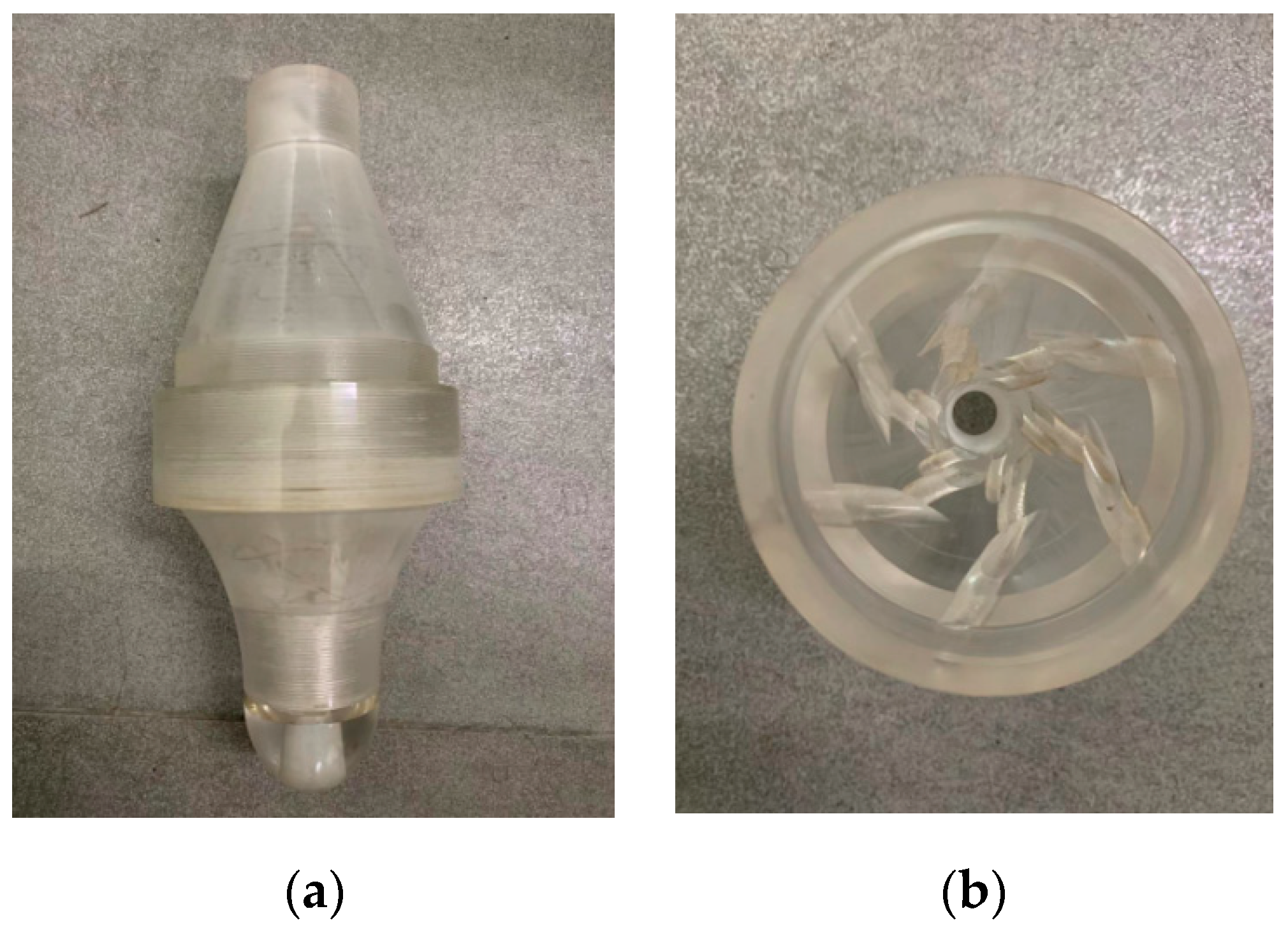
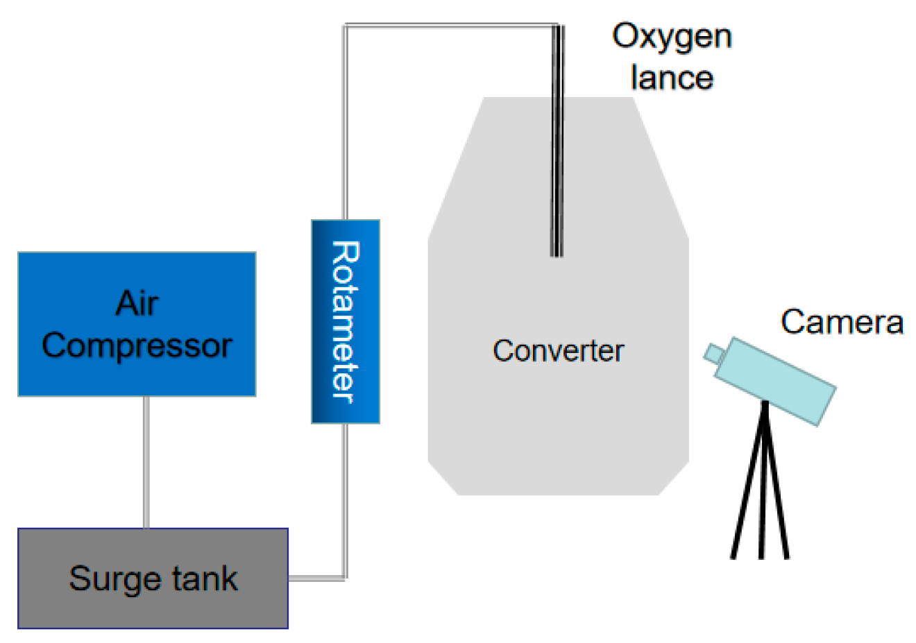
2.1. Physical Model and Model Validation

Yoshihiko Higuchi and Yukari Tago considered that for the “nozzle twist lance”, the suppression effect on the splashing rate can be attributed to part of the jet pressure shifting from the axis of the oxygen lance to the tangential direction [26]. It is thought that if airflow similar to a tornado can be obtained, the upward splashing behavior in the converter should be restrained. According to this theory, a new cyclone nozzle is designed in this present study. As shown in Figure 1, there are three layers of air inlet channels in the nozzle that can rotate the airflow tangent to the air outlet channel. From the exit, a tornado jet can be obtained.
A water model experimental reactor in a one-sixth-scaled 120 t converter was constructed to investigate the flow pattern and splashing behavior. The parameters of converters and oxygen lance are achieved to build the physical model based on the similarity of kinetics and geometry [27]. The modified Froude number is applied to make the model dynamically similar to the actual converter by considering inertial and gravity (Equation (1))
F r = ρ g ρ l ρ g v 2 g g d ρ g ρ l v 2 g g d
The conversion can get Equation (2)
Q Q 1 = ( d d 1 ) 5 × ρ l ρ g ρ l 1 ρ g 1 × ρ g 1 ρ g
where Q , Q 1 stand for gas flows of the physical model and the prototype of converter (m3/h); ρ l , ρ l 1 stand for liquid density of the physical model and prototype of converter (kg/m3); ρ g , ρ g 1 present oxygen density of the physical model and prototype of converter (kg/m3); v g v g 1 stand for gas velocities of the model and prototype (m/s); g acts as acceleration of gravity (m/s2); d, d1 are characteristic size of system; and the subscripts l and g are short for liquid and gas.
At the beginning, as presented in the Section 2.4, the structure of the new oxygen lance is optimized by numerical simulation results. Then, the prototype of converter and warter model parameters are established and presented in Table 1. Based on the experimental parameters, the cavity depth and width are obtained under different lance heights. Thereafter, the physical model is simulated by the VOF model through Fluent19.2 software. Next, the representative cavity profiles are compared for model validation.
The simulation consequences were compared with the physical model experiment results in order to validate the numerical model under the parameters of Table 1. Figure 2 shows the experimental device. Figure 3 compares the representative cavities obtained by the water and numerical model. As seen from this figure, the simulation results are in good agreement with the measured results. Therefore, it can be concluded that the present numerical model can be applied to analyze the jet behavior. On this basis, the numerical model is applied in this study to research the cyclone oxygen lance jet.

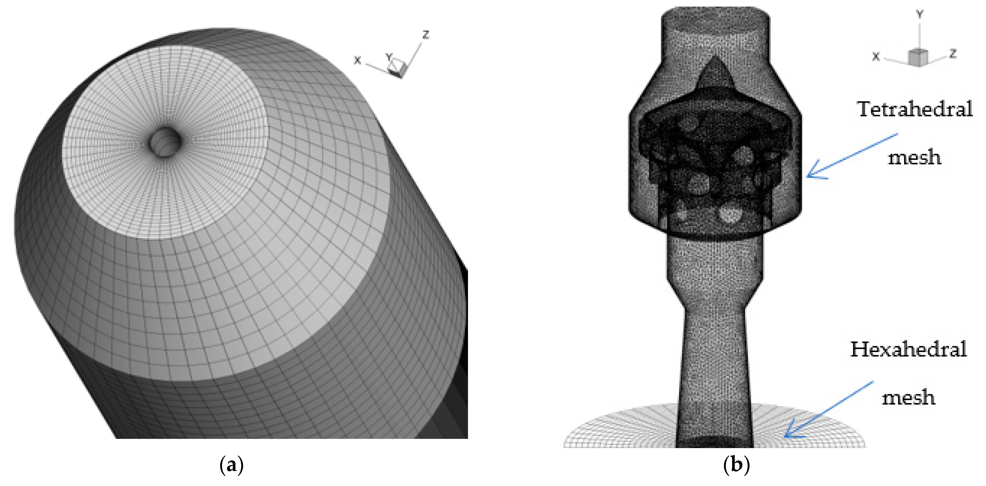
2.2. Numerical Model

The model, mesh of converter, and cyclone oxygen lance are presented in Figure 4. The computational mesh is constructed using ICEM CFD 19.2, and due to the complex structure of the new nozzle the hybrid mesh is applied (Tetrahedral mesh is applied to the new nozzle; Hexahedral mesh is applied to the converter). For the purpose of adapting to the great variation of velocity, temperature gradient, and the motion capture of the gas-liquid interface, the mesh refinement is carried out in the main flow area of the jet and near the gas-liquid interface. The supersonic compressible equation is used to describe the top-blown supersonic jet, and the VOF (Volume of Fluid) numerical model is coupled to describe the liquid dimpling formed by the top-blown jet impinging on the molten steel. The physical parameters of molten steel-slag-oxygen are shown in Table 2.
The Top-blown process of the converter is extremely complex and difficult to observe. Therefore, the complex chemical reactions between molten steel, slag, and gas are not considered. To simplify the simulation, the following assumptions were made:
  • The Newtonian fluid is adopted to simulate the fluid flow in the converter;
  • Oxygen is assumed as an ideal gas;
  • A no-slip condition is applied to the wall, and the heat transfer process between the wall and molten bath is ignored. The standard wall function is applied to solve the average velocity near the wall.

2.3. Boundary Conditions and Solution Methods

The stagnant pressure is applied to the pressure inlet, and the pressure outlet is equal to the external atmospheric pressure.
The pressure-velocity coupling scheme adopts the PISO (Pressure-Implicit with splitting of Operators) algorithm with the unsteady solution mode during numerical simulation. The interpolation of the pressure values is achieved using the Pressure Staggering Option (Pressure Staggering Option, PRESTO!) and a second-order upwind scheme. The VOF (Volume of Fluid) numerical model is applied to track the interface. Moreover, the CICSAM (Compressive Interface-Capturing Scheme for Arbitrary Meshes) is used to capture the sharp-free interface.
The initial time step is set to 10−6 s. The time step can be slightly increased with the gradual stabilization of the calculation, and the Courant number should be limited to less than 1. The convergence criterion of energy residuals was 10−6. Other variables adopt the default criterion.
In order to test the independence of the grid, three hybrid grid schemes of 909337, 1183611, and 1829641 are selected for simulation. The calculation consequences show that when the mesh size is fine enough (for the mesh schemes of 1183611 and 1829641), the simulation results are independent of the mesh size. Thus, the scheme of 1183611 is applied in the present study.

2.4. Optimization of Cyclone Oxygen Lance

In order to get the best structure of cyclone nozzle, many works have been done by means of numerical simulation. In this study, the parameters that should be modified better were found by analyzing the numerical simulation results. Then, the model was updated and simulated again.
As shown in Figure 5, there are many small vortexes (marked by the red circles) on one side of the channels, at the first and third layers, which will lead to the loss of energy. The reason should be that the airflow is obstructed when it passes through the swirling layer due to the sharp air intake structure. Finally, as shown in Figure 6, the cyclone nozzle was optimized by a series of modifications.
The simulation consequences of the modified model are presented in Figure 7. As seen from these figures, the flow field of the optimized cyclone nozzle has no obvious swirls than before, which can better take advantage of the cyclone nozzle. Moreover, the effect of the cyclone nozzle on the molten bath is compared and analyzed between the two simulation results. From Figure 8, it can be concluded that the optimized cyclone nozzle considerably reduces the splashing behavior compared to before.

3. Discussion and Results

3.1. Effect of Cyclone Oxygen Lance on Supersonic Region

Under the same conditions, the Mach number is plotted against the distance from the nozzle exit in Figure 9 under the same conditions. It can be seen from Figure 9 that the supersonic region of the Laval nozzle (0.77 m) is shorter than that of the cyclone nozzle (1.06 m) under the same conditions. This is because that the exit diameter of the cyclone nozzle is larger than that of the Laval nozzle, which is effective to maintain higher velocity and prolong the supersonic region for the cyclone oxygen lance jet.
Another advantage of the cyclone nozzle is that there is no jet coalescence because it only has one exit. The jet coalescence of traditional oxygen lance weakens the effect of the single jets because the jets swallow a lot of the surrounding medium.

3.2. Effect of Cyclone Oxygen Lance on Droplet Generation

The effect of the nozzle structure on the droplet generation is investigated to evaluate the nozzle design for the cyclone oxygen jet. The blowing number (NB) is used to evaluate the droplet production in a top-blown process [28,29] and is denoted as follow:
N B = ρ g u g 2 2 ρ l σ l g
where ρ g and ρ l stand for the density of oxygen and molten steel (kg/m3); u g stands for the critical oxygen velocity (m/s) [30,31,32]; σ stands for the surface tension (N/m); g stands for the acceleration of gravity (m2/s). The droplet formation rate per unit volume of top-blown oxygen can be obtained by Equation (4) by means of the blowing number calculated by Equation (3):
R F = ( N B ) 3.2 [ 2.6 × 10 6 + 2.0 × 10 4 ( N B ) 12 ] 0.2
where R stands for the droplet formation; F stands for the volume flow of top-blown gas (m3/h). Table 3 shows the NB distributions of the traditional nozzle and new nozzle under different conditions.
As shown in Table 3, the cyclone nozzle has a larger droplet formation than the Laval nozzle, and the rate of droplet formation decreases with the lance height increasing from 1100 mm to 1550 mm similar to the Laval nozzle. The law of the traditional Laval nozzle is similar to that of [8]. The generation of droplets increases with the increasing of flow rate and the decreasing of lance height.

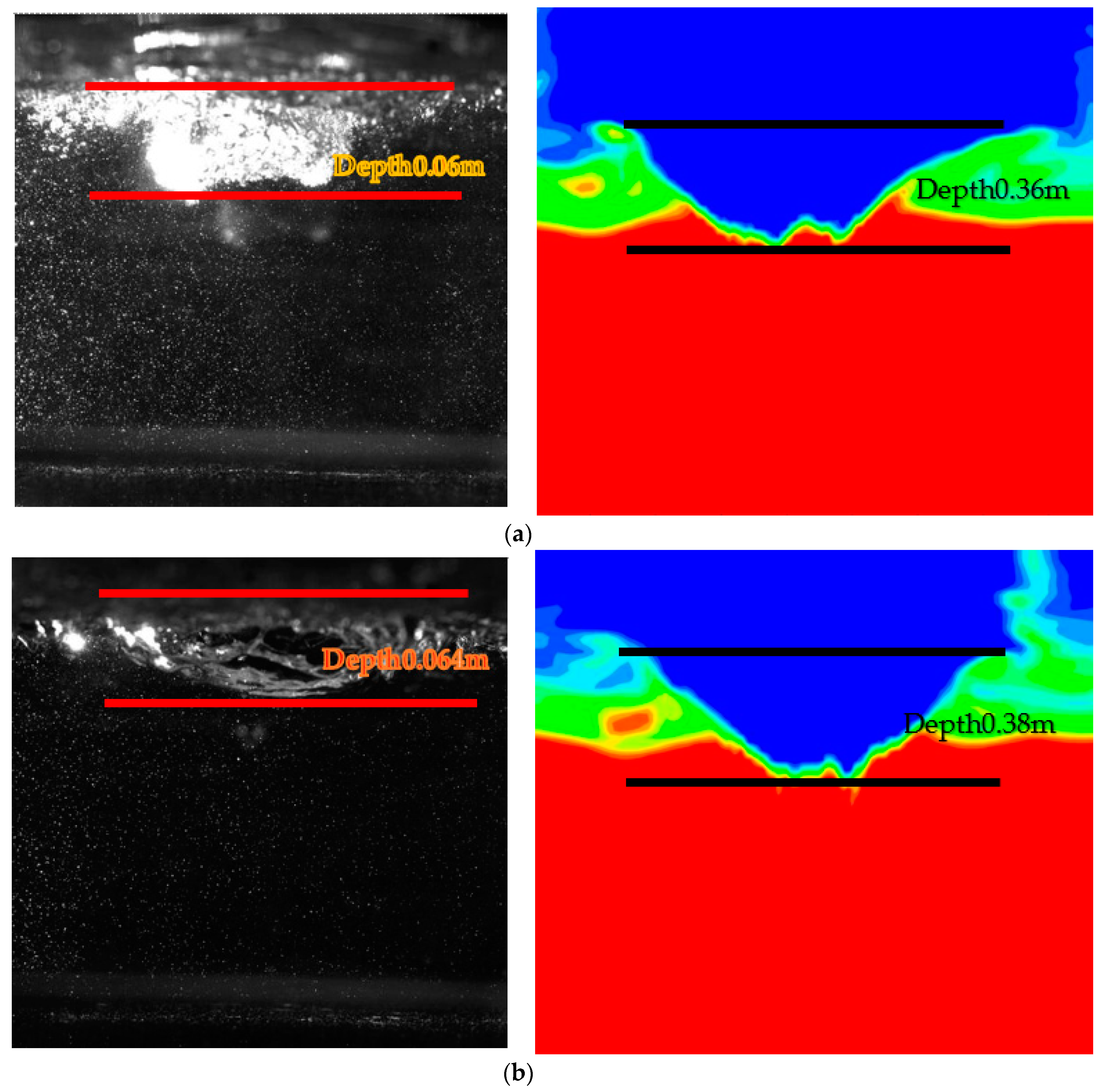
3.3. Effect of Cyclone Oxygen Lance on Upward Splashing and Penetrating Depth

As seen from Figure 10, the upward splashing (marked by the red circles) is obvious for the traditional Laval nozzle, while there is hardly upward splashing for the cyclone nozzle under the same conditions. The suppression effect on the splashing can be attributed to part of the jet pressure shifting from the axis of the oxygen lance to the tangential direction. It means that if the splashing exists, it will splash along the edge of the cavity rather than in the direction of the oxygen lance. Therefore, it can be concluded that compared with the conventional oxygen lance, the cyclone oxygen lance may improve the problems of sticking and burning lance due to the jet of cyclone oxygen lance blowing downward vertically, which can be supported by Figure 11, where the nozzle exit temperature of cyclone oxygen lance is 200 K lower than that of the Laval oxygen lance.
From Figure 10, it can be concluded that the depth of the cavity formed by the cyclone oxygen lance jets impinging on the molten bath is obviously larger than that of the traditional Laval nozzle under conditions of a, b, and c, which are the significant parameters of hard blowing used in the stage of deep decarbonization. In other words, for obtaining the same penetrating depth, the cyclone lance height can be higher than that of a conventional oxygen lance, which leads to a better protective effect on the refractories of the oxygen lance.
For the cyclone nozzle itself, it can be concluded from parts a and b of Figure 10 that when the lance height increases from 1100 mm to 1550 mm, the penetration depth decreases from 0.55 m to 0.38 m. Similarly, it also can be concluded from Figure 10b,c that when the operation pressure decreases from 1 Mpa to 0.8 Mpa, the penetration depth decreases from 0.55 m to 0.45 m. The consequences are consistent with the practical application that converter operators often adjust the lance height and operation pressure to control blowing property.

3.4. Effect of Cyclone Oxygen Lance on Turbulence Kinetic Energy Distribution

In Figure 12, the turbulent kinetic energy is plotted against the radial distance under different axial locations and different operation pressures. In Figure 13, turbulent kinetic energy and turbulent dissipation rate is plotted against the axial distance under different operation pressures. It can be concluded that the turbulence is restricted when the jets are sprayed from the exit. As a result, relatively small turbulent kinetic energy is obtained. As the jets continue to spray downward, shown in Figure 12a,b, the development of turbulence is improved as a result of the radial expansion of the jets. However, as shown in Figure 13, the turbulent kinetic energy slowly increases to a maximum value and then begins to decrease because of the attenuation of turbulent fluctuation. It can also be found in Figure 13a: the turbulent kinetic energy will reach a larger value at a higher operation pressure. The increasing of the turbulent kinetic energy can result in more intense fluctuations at the interface between oxygen and slag and improve the slagging. As shown in Figure 13b, the trend of the turbulent dissipation rate is consistent with that of the turbulent kinetic energy.
Figure 14 presents the radial distributions of the turbulent kinetic energy of Laval and cyclone nozzles at the interface between oxygen and slag under different operating pressures and lance height. Table 4 shows the average value of turbulent kinetic energy of Laval and cyclone nozzles at the interface between oxygen and slag under different operating pressures and lance height. Based on the results, at the interface between oxygen and slag, the maximum turbulent kinetic energy increases with the operating pressure increasing and lance height decreasing. Laval and cyclone nozzles both follow this law proposed above. From the calculation results shown in Table 4, the average value of turbulent kinetic energy of cyclone nozzle is larger than that of the conventional Laval nozzle, which may be related to the tornado jet formed by the cyclone nozzle. As presented in Figure 15, the molten bath can obtain rotating kinetic energy.

4. Conclusions

In this present article, the effect of cyclone nozzle on the upward splashing behavior, penetrating depth, and reaction area of molten bath compared with traditional oxygen lance were investigated for the purpose of proposing scientific theoretical basis for the lance design and practical application of cyclone oxygen lance. The interaction behavior between the top-blown jet and molten bath under different conditions is investigated through hydrodynamic and mathematical methods. Some useful results have been achieved and the conclusions are as follows:
  • Compared with traditional Laval oxygen lance, cyclone oxygen lance can retain higher impact velocity and prolong the supersonic region. Moreover, there is no jet coalescence because the cyclone nozzle only has one exit. Both of these aspects are useful for the jets impinging on the molten bath.
  • The cyclone nozzle has a larger droplet formation rate than that of the conventional nozzle, which can help the converter to promote productivity. Similar to the traditional Laval nozzle, the droplet formation rate decreases with increasing lance height.
  • Compared with the conventional Laval oxygen lance, the cyclone oxygen lance can reduce the upward splashing and, thereby, reduce the physical erosion of the furnace lining as a result of part of the jet pressure shifting from the axis of the oxygen lance to the tangential direction. In the steelmaking process, reducing the erosion of the furnace lining is of great economic benefit to the steel-making plant. Similar to the law of the Laval nozzle affecting the molten bath, the penetration depth is inversely proportional to the lance height and proportional to the operating pressure for the new nozzle.
  • Under the same inlet flow rate, pressure, and lance height, the penetration depth formed by the cyclone oxygen lance jet impinging on the molten bath is larger than that of the conventional Laval nozzle. Therefore, the cyclone oxygen lance can increase the blowing efficiency and improve the utilization rate of oxygen and metal yield, which is of great economic benefit to the steel-making plant.
  • The turbulent kinetic energy and turbulent dissipation rate of jets initially increases and then decreases along the axial direction. The maximum value of turbulent kinetic energy and turbulent dissipation rate of jets increases with increasing operating pressure. The average value of the turbulent kinetic energy of the cyclone nozzle is larger than that of the conventional Laval nozzle at the interface between oxygen and slag, which may be related to the tornado jet formed by the cyclone nozzle. The increasing of the turbulent kinetic energy can result in more intense fluctuations at the interface between oxygen and molten slag, which can improve the slagging and, thus, promote the blowing efficiency.

5. Patents

Patent of the people’s Republic of China, the patent number is ZL 2018 1 0767819.9.

Author Contributions

Conceptualization, J.L., C.C., and J.Z.; data curation, J.L.; formal analysis, J.L.; funding acquisition, B.W.; investigation, J.L., J.Z., and B.W.; methodology, J.L. and B.W.; project administration, B.W.; resources, J.L., J.Z., and B.W.; supervision, B.W.; validation, J.L. and Z.M.; writing–original draft, J.L.; writing–review & editing, J.L., J.Z., and B.W. All authors have read and agreed to the published version of the manuscript.

Funding

This research was funded by the Innovation Program of the Shanghai Municipal Education Commission (NO.2019-01-07-00-09-E00024), Science and Technology Commission of Shanghai Municipality (NO.19DZ2270200, 20511107700), and Independent Research and Development Project of State Key Laboratory of Advanced Special Steel, Shanghai Key Laboratory of Advanced Ferrometallurgy, Shanghai University (SKLASS 2021-Z02).

Institutional Review Board Statement

Not applicable.

Informed Consent Statement

Not applicable.

Data Availability Statement

Not applicable.

Acknowledgments

The authors gratefully acknowledge the resources partially provided by the State Key Laboratory of Advanced Special Steel, Shanghai University of Materials Science and Engineering.

Conflicts of Interest

The authors declare no conflict of interest.

References

  1. Higuchi, Y.; Tago, Y. Effect of lance design on jet behavior and spitting rate in top blown process. ISIJ Int. 2001, 41, 1454–1459. [Google Scholar] [CrossRef] [Green Version]
  2. Fabritius, T.M.J.; Luomala, M.J.; Virtanen, E.O.; Tenkku, H.; Fabritius, T.L.J.; Siivola, T.P.; Härkki, J.J. Effect of bottom nozzle arrangement on splashing and spitting in combined blowing converter. ISIJ Int. 2002, 42, 861–867. [Google Scholar] [CrossRef]
  3. Sabah, S.; Brooks, G. Splash distribution in oxygen steelmaking. Metall. Mater. Trans. B 2015, 46, 863–872. [Google Scholar] [CrossRef]
  4. Liu, G.; Liu, K.; Han, P.; Chen, Y. Numerical investigation on behaviors of interlaced jets and their interaction with bath in BOF steelmaking. AIP Adv. 2019, 9, 075202. [Google Scholar] [CrossRef]
  5. Sun, Y.H.; Liang, X.T.; Zeng, J.H.; Chen, J.; Chen, L. Numerical simulation and application of oxygen lance in 120t BOF of PANSTEEL. Ironmak. Steelmak. 2016, 44, 76–80. [Google Scholar] [CrossRef]
  6. He, C.; Yang, N.; Huang, Q.; Liu, C.; Wu, L.; Hu, Y.; Fu, Z.; Gao, Z. A Multi-Phase Numerical Simulation of a Four-Nozzle Oxygen Lance Top-Blown Convertor. Procedia Earth Planet. Sci. 2011, 2, 64–69. [Google Scholar] [CrossRef] [Green Version]
  7. Alam, M.; Naser, J.; Brooks, G.; Fontana, A. A Computational Fluid Dynamics Model of Shrouded Supersonic Jet Impingement on a Water Surface. ISIJ Int. 2012, 52, 1026–1035. [Google Scholar] [CrossRef] [Green Version]
  8. Dong, K.; Zhu, R.; Liu, F. Behaviours of supersonic oxygen jet with various Laval nozzle structures in steelmaking process. Can. Metall. Q. 2018, 58, 285–298. [Google Scholar] [CrossRef]
  9. Li, Q.; Li, M.; Kuang, S.B.; Zou, Z. Computational study on the behaviours of supersonic jets and their impingement onto molten liquid free surface in BOF steelmaking. Can. Metall. Q. 2014, 53, 340–351. [Google Scholar] [CrossRef]
  10. Alam, M.; Naser, J.; Brooks, G. Computational Fluid Dynamics Simulation of Supersonic Oxygen Jet Behavior at Steelmaking Temperature. Metall. Mater. Trans. B 2010, 41, 636–645. [Google Scholar] [CrossRef]
  11. Hosseini, M.; Arasteh, H.; Afrouzi, H.; Toghraie, D. Numerical simulation of a falling droplet surrounding by air under electric field using VOF method: A CFD study. Chin. J. Chem. Eng. 2020, 28, 2977–2984. [Google Scholar] [CrossRef]
  12. Azadbakhti, R.; Pourfattah, F.; Ahmadi, A.; Akbari, O.A.; Toghraie, D. Eulerian–Eulerian multi-phase RPI modeling of turbulent forced convective of boiling flow inside the tube with porous medium. Int. J. Numer. Methods Heat Fluid Flow 2019, 30, 2739–2757. [Google Scholar] [CrossRef]
  13. Nemati, M.; Abady, A.R.S.N.; Toghraie, D.; Karimipour, A. Numerical investigation of the pseudopotential lattice Boltzmann modeling of liquid–vapor for multi-phase flows. Phys. A Stat. Mech. Appl. 2018, 489, 65–77. [Google Scholar] [CrossRef]
  14. Sun, Y.-L.; Rahmani, A.; Saeed, T.; Zarringhalam, M.; Ibrahim, M.; Toghraie, D. Simulation of deformation and decomposition of droplets exposed to electro-hydrodynamic flow in a porous media by lattice Boltzmann method. Alex. Eng. J. 2022, 61, 631–646. [Google Scholar] [CrossRef]
  15. Toghaniyan, A.; Zarringhalam, M.; Akbari, O.A.; Shabani, G.A.S.; Toghraie, D. Application of lattice Boltzmann method and spinodal decomposition phenomenon for simulating two-phase thermal flows. Phys. A Stat. Mech. Appl. 2018, 509, 673–689. [Google Scholar] [CrossRef]
  16. Jia, Y.; Zeng, M.; Barnoon, P.; Toghraie, D. CFD simulation of time-dependent oxygen production in a manifold electrolyzer using a two-phase model. Int. Commun. Heat Mass Transf. 2021, 126, 105446. [Google Scholar] [CrossRef]
  17. Liu, F.; Sun, D.; Zhu, R.; Zhao, F.; Ke, J. Effect of nozzle twisted oxygen lance on flow field and dephosphorisation rate in converter steelmaking process. Ironmak. Steelmak. 2016, 44, 640–648. [Google Scholar] [CrossRef]
  18. Sambasivam, R.; Lenka, S.N.; Durst, F.; Bock, M.; Chandra, S.; Ajmani, S.K. A New Lance Design for BOF Steelmaking. Metall. Mater. Trans. B 2007, 38, 45–53. [Google Scholar] [CrossRef]
  19. Li, Q.; Li, M.; Kuang, S.; Zou, Z. Numerical Simulation of the Interaction Between Supersonic Oxygen Jets and Molten Slag–Metal Bath in Steelmaking BOF Process. Metall. Mater. Trans. B 2015, 46, 1494–1509. [Google Scholar] [CrossRef]
  20. Meidani, A.R.N.; Isac, M.; Richardson, A.; Cameron, A.; Guthrie, R.I.L. Modelling shrouded supersonic jets in metallurgical reactor vessels. ISIJ Int. 2004, 44, 1639–1645. [Google Scholar] [CrossRef] [Green Version]
  21. Cao, L.L.; Liu, Q.; Wang, Z.; Li, N. Interaction behaviour between top blown jet and molten steel during BOF steelmaking process. Ironmak. Steelmak. 2016, 45, 239–248. [Google Scholar] [CrossRef]
  22. Lv, M.; Zhu, R. Research on coherent jet oxygen lance in BOF steelmaking process. Metall. Res. Technol. 2019, 116, 502. [Google Scholar] [CrossRef]
  23. Li, M.; Li, Q.; Kuang, S.B.; Zou, Z. Coalescence Characteristics of Supersonic Jets from Multi-Nozzle Oxygen Lance in Steelmaking BOF. Steel Res. Int. 2015, 86, 1517–1529. [Google Scholar] [CrossRef]
  24. Asahara, N.; Naito, K.-I.; Kitagawa, I.; Matsuo, M.; Kumakura, M.; Iwasaki, M. Fundamental Study on Interaction between Top Blown Jet and Liquid Bath. Steel Res. Int. 2011, 82, 587–594. [Google Scholar] [CrossRef]
  25. Cao, L.L.; Wang, Y.N.; Liu, Q.; Feng, X.M. Physical and Mathematical Modeling of Multiphase Flows in a Converter. ISIJ Int. 2018, 58, 573–584. [Google Scholar] [CrossRef] [Green Version]
  26. Higuchi, Y.; Tago, Y. Effect of nozzle twisted lance on jet behavior and spitting rate in top blown process. ISIJ Int. 2003, 43, 1410–1414. [Google Scholar] [CrossRef] [Green Version]
  27. Lv, M.; Zhu, R.; Wang, H.; Bai, R. Simulation and Application of Swirl-Type Oxygen Lance in Vanadium Extraction Converter. Steel Res. Int. 2013, 84, 304–312. [Google Scholar] [CrossRef]
  28. Subagyo, G.B.; Coley, K.; Irons, G. Generation of droplets in slag-metal emulsions through top gas blowing. Chem. Eng. Sci. 2002, 57, 663. [Google Scholar] [CrossRef] [Green Version]
  29. Rout, B.K.; Brooks, G.; Rhamdhani, M.A.; Li, Z. Modeling of droplet generation in a top blowing steelmaking process. Metall. Mater. Trans. B 2016, 47, 3350–3361. [Google Scholar] [CrossRef] [Green Version]
  30. He, Q.L.; Standish, N. A model study of droplet generation in the BOF steelmaking. ISIJ Int. 1990, 30, 305–309. [Google Scholar] [CrossRef]
  31. Standish, N. Drop generation due to an impinging jet and the effect of bottom blowing in the steelmaking vessel. ISIJ Int. 1989, 29, 455–461. [Google Scholar] [CrossRef] [Green Version]
  32. Sumi, I.; Kishimoto, Y.; Kikuchi, Y.; Igarashi, H. Effect of high-temperature field on supersonic oxygen jet behavior. ISIJ Int. 2006, 46, 1312–1317. [Google Scholar] [CrossRef] [Green Version]
Figure 1. The schematic view of cyclone nozzle: (a) external shape of cyclone nozzle; (b) internal shape of cyclone nozzle.
Processes 10 00507 g001
Figure 2. Schematic diagram of experimental equipment.
Processes 10 00507 g002
Figure 3. Comparison of the consequences between physical model and numerical simulation (lance height 1550 mm, operation pressure 1.0 Mpa): (a) comparison of the consequences between physical model and numerical simulation at 5 s; (b) comparison of the consequences between physical model and numerical simulation at 10 s.
Processes 10 00507 g003
Figure 4. Mesh and structure of converter and cyclone nozzle: (a) mesh of converter; (b) mesh of cyclone nozzle.
Processes 10 00507 g004
Figure 5. Numerical simulation results of cyclone nozzles simulated by the pre-modified model: (a) velocity contours and vector diagrams of the first layer of cyclone nozzle; (b) velocity contours and vector diagrams of the second layer of cyclone nozzle; (c) velocity contours and vector diagrams of the third layer of cyclone nozzle.
Processes 10 00507 g005
Figure 6. Comparison between the pre-modified structure and the modified structure: (a) pre-modified model; (b) modified model.
Processes 10 00507 g006
Figure 7. Numerical simulation results of cyclone nozzles simulated by the modified model: (a) velocity contours and vector diagrams of the first layer of cyclone nozzle after optimization; (b) velocity contours and vector diagrams of the third layer of cyclone nozzle after optimization.
Processes 10 00507 g007
Figure 8. Comparison of interaction behavior between the pre-modified model and modified model: (a) density diagrams of interaction between nozzle and molten bath before optimization; (b) density diagrams of interaction between nozzle and molten bath after optimization.
Processes 10 00507 g008
Figure 9. Comparison of Mach number between Laval and cyclone oxygen lances (lance height 1100 mm, operation pressure 0.8 Mpa).
Processes 10 00507 g009
Figure 10. Comparison of interaction behavior between Laval and cyclone oxygen lances under different parameters: (a) comparison of interaction behavior between Laval and cyclone oxygen lances (lance height 1550 mm, operation pressure 1.0 Mpa); (b) comparison of interaction behavior between Laval and cyclone oxygen lances (lance height 1100 mm, operation pressure 1.0 Mpa); (c) comparison of interaction behavior between Laval and cyclone oxygen lances (lance height 1100 mm, operation pressure 0.8 Mpa).
Processes 10 00507 g010
Figure 11. Comparison of nozzle exit temperature between Laval and cyclone oxygen lances under the same parameters: (a) nozzle exit temperature of Laval oxygen lance; (b) nozzle exit temperature of Cyclone oxygen lance.
Processes 10 00507 g011
Figure 12. Radial distributions of turbulence kinetic energy of cyclone nozzle at different axial locations under different operating pressure and lance height of 1100 mm: (a) 0.4 m from nozzle exit; (b) 1.1 m from nozzle exit (interface between oxygen and slag).
Processes 10 00507 g012
Figure 13. Axial distributions of turbulent kinetic energy and turbulent dissipation rate of cyclone nozzle under different operating pressure: (a) distributions of turbulent kinetic energy; (b) distributions of turbulent dissipation rate.
Processes 10 00507 g013
Figure 14. Radial distributions of turbulent kinetic energy of Laval and cyclone nozzles at the interface between oxygen and slag under different operating pressures and lance height: (a) Laval nozzle; (b) cyclone nozzle.
Processes 10 00507 g014
Figure 15. Vector diagram of the interface between oxygen and slag.
Processes 10 00507 g015
Table 1. Parameters of prototype and physical model.
ParameterPrototypeModel
Bath height/mm1336223
Slag thickness/mm20034
Number of nozzles1 for Cyclone, 4 for Laval1 for Cyclone
Lance height/mm1550 and 1100258 and 183
Bath diameter/mm4960827
Throat diameter/mm80 for Cyclone, 40 for Laval14 for Cyclone
Top gas flow rate/Nm3 h−116,81176
Table 2. Property parameters of steel-slag-oxygen.
ParameterMolten SteelSlagOxygen
Density/(kg·m−3)71003500Compressible
Viscosity/(kg·m−1·s−1)0.00650.11.19 × 10−5
Thermal Conductivity/(W·m−1·K−1)401.70.0246
Specific heat capacity(J·kg−1·K−1)6701200919.31
Surface tension/(N·m−1)1.60.55
Temperature/K18731873300
Table 3. The calculation results of NB and R/F (operation pressure 0.8 Mpa).
Lance Height (mm)Laval NozzleCyclone Nozzle
NBR/FNBR/F
11005.9629.7820.8261.18
15503.137.4411.3350.33
Table 4. The average value of the turbulent kinetic energy of Laval and cyclone nozzle at the interface between oxygen and slag under different operating pressures and lance heights.
ParametersLaval NozzleCyclone Nozzle
0.8 Mpa-1100 mm23108880
1.0 Mpa-1100 mm282010,010
1.0 Mpa-1550 mm22305150
Publisher’s Note: MDPI stays neutral with regard to jurisdictional claims in published maps and institutional affiliations.

