Article

Design and Experimental Research of a New Film-Picking Mulch Film Recovery Machine with Impurity Separation Function

1
College of Mechanical and Electrical Engineering, Shihezi University, Shihezi 832003, China
2
Northwest Key Laboratory of Agricultural Equipment, Ministry of Agriculture and Rural Affairs, Shihezi 832003, China
3
Servo System Research and Design Institute of Automation Research and Design Institute of Metallurgical Industry, Co., Ltd., Beijing 100071, China
*
Author to whom correspondence should be addressed.
Processes 2022, 10(3), 455; https://doi.org/10.3390/pr10030455
Submission received: 19 January 2022 / Revised: 17 February 2022 / Accepted: 21 February 2022 / Published: 24 February 2022

Abstract

:
When the film is under no stress, it does not show any stiffness or capability to withstand loads. Therefore, with the help of ANSYS motion, the author applied pre-stress, controlled point coordinates and the equation of equivalent stress surface and used form-finding conditions to explore the equilibrium state of the films in different depths. The author established curve fitting equations and designed a new membrane-removing mulch film recovery machine. The author also analyzed key components and separately established regression equations between recovery rate, damage rate, release rate and the working angle of film picking mechanism, as well as the regression equation between the depth of picking mechanism into the soil and the working angle of clamping conveyor. Then the author conducted the variance analysis on these regression equations. By using Design Expert 8.0.6 to optimize the solution, when the working angle of the pick-up mechanism is 27.31°, the depth of the pick-up mechanism is 73.0 mm. The working angle of the clamping and conveying device is 38.33°, the recovery rate is 93.9% and the damage rate is 89.3%. The test result shows that when parameters are set as above values, the recovery rate of residual film is 92.5%, the release rate is 87.6% and the error values of damage rate and release rate are both lower than 1.5%, which have verified the feasibility of the optimization solution. The experimental result can work as a reference for the optimum working parameters of the new membrane-removing mulch film recovery machine.

1. Introduction

The film mulching cultivation technique has obvious efficiency of water-saving, heat preservation, salt suppression and yield increasing, which has been widely applied in the field of mass agriculture production. As a big agriculture province, Xinjiang has varieties of cash crops, and its film coverage area of farm corps is kept beyond 759.31 khm2 per year. Taking cotton as an example, Xinjiang holds 8% of the world’s total output [1,2,3]. Compared with planting cotton in open fields, planting cotton with film mulching cultivation can increase the production by 30~50% in general and 40~60% at most. According to statistics, mulch film could be detained for 8~10 years in the soil, and the average residue quantity of waste film reaches 187.5 kg per hectare, which causes the production to reduce by 17% [4,5,6,7,8,9,10,11,12]. The looser the soil is, the lower the moisture content and viscosity are, and the higher the plastic film pick-up rate is. “White pollution” has affected the sustainable development of agriculture [13,14,15,16,17,18,19,20,21,22]. Mechanized residual film recovery technique provides an effective means for residual film recovery, but the structure is more complicated, the reliability is low, and the recovery effect is poor [23].
In the 1980s, domestic and foreign agricultural machinery scholars started the research on residual film recycling machines. According to different working principles, film recovery machines could be classified into many types, such as clamping finger-chain, arc tooth, rolling bundle and chain screen [24,25,26]. When the finger chain mulch film recovery machine is working, the finger picks up the remaining film around the pitch line of the lower sprocket. When passing the upper sprocket, the finger stretches and the mulch film drops to the collecting box due to gravity. The arc tooth and rolling bundle residual film recycling machine collects films by spike tooth. Missed films are pierced again by spike tooth after being tucked up by the film raking spring-finger. When the spike tooth is pierced into the soil too fast, the impact force is too much, which tears the films into strips and makes it impossible to pick up the films. When the chain screen residual film recycling machine is working, the digging shovel scoops up the mixture of mud and film. Through shaking in the chain tooth, film impurity separation is performed on the screen surface. However, in the recovery process, when the speed of the sprocket mechanism is too low, the residence time of the mixture is relatively short, and the screening cannot be achieved. In accordance with the problems such as low recovery rate, high impurity rate and high damage rate in the residual film recycling process, the paper designed a new membrane removing mulch film recovery machine, which can achieve film impurity separation in the process of residual films picking up. The new machine could achieve collecting more films in the previous work stroke and separate more impurities without detaching from mulch films in the post-work stroke. Moreover, the machine applies pre-stress to the film along and perpendicular to the membrane line. The machine controls point coordinates and iso-stress surface equation to determine the action range of the angle and depth of the film pick-up mechanism when the machine is working. This paper applied the Design Expert 8.0.6 optimization solution and was verified through experiments. The 0.008 mm–0.010 mm white polyethylene agricultural film is commonly used in recyclable cotton fields.

2. Experimental Method

In the residual film recycling process, fracture elongation is one of the mechanical property indexes to measure the strength of residual films. In the general case, fracture elongation is the ratio of displacement increments to initial line mark distance when the specimen is at the point of tension fracture:
δ b = L L 0 L 0
where
  • δ b = the fracture elongation (%);
  • L = the marking distance at the point of tension fracture (mm);
  • L 0 = the initial line mark distance (mm).
The tensile test condition parameters are as shown in Table 1.
The tensile load and deformation curve are shown in Figure 1. As the soil layer depth increases, the tensile force F of tearing residual film shows an overall decreasing trend. When h is larger than 110 mm but no more than 120 mm, the water content w is 9.63%. According to the tensile force and deformation diagram, the energy generated by the resistance of the residual film to soil and impurity resistance is 1.52 J, and the tensile force is 1.393 N–1.432 N. When the soil depth is 100 mm < h ≤ 110 mm, the moisture content “w” is 11.72%, the energy produced is 4.11 J and the tensile force is 1.115 N~1.373 N. When 70 mm < h ≤ 90 mm, the moisture content “w” is 16.13%, the energy produced is less than 1.2 J and tensile force is 1.314 N~1.388 N, which has no significant difference.
In the process of plastic deformation, the polynomial fitting is separately applied on the tensile force–deformation curve when the soil depth is 90 mm < h ≤ 120 mm, which is as shown in Equation (2).
y = { E 12 x 4 + 5 E 0 . 9 x 3 0 . 6 x 2 + 0 . 0047 x + 0 . 4194 R 2 = 0 . 9158 2 E 15 x 5 12 x 4 0 . 8 x 3 0 . 5 x 2 + 0 . 0059 x + 0 . 5376 R 2 = 0 . 9213 4 E 16 x 5 12 x 4 0 . 9 x 3 0 . 6 x 2 + 0 . 0039 x + 0 . 6242 R 2 = 0 . 9172
where
  • E = the constant 10;
  • R2 = the correlation coefficient of the polynomial fitting, which characterizes the degree of the linear correlation;
  • x = the represents deformation extent, and y represents tensile force.
According to Chinese Standard, the regulation of surface and deep mulch films in GB/T 25412-2010 is as follows: when the distance to the ground surface is 0 mm~100 mm, it belongs to surface mulch film; when the distance is over 100 mm, it belongs to deep mulch film. After previous experiments, the mechanical property of the mulch film is assured to be negligible when the distance to the ground surface is over 120 mm. Preliminary experiments also studied the mechanical properties between the shallow mulch film ranging 0 mm to 100 mm from the mulch film soil surface and mulch film ranging 100 mm to 120 mm from part of the deep soil surface.
From the above equation, we can establish that when the soil depth is 90 mm < h ≤ 120 mm, the full force is 1.29 N based on the Lagrange interpolation method.

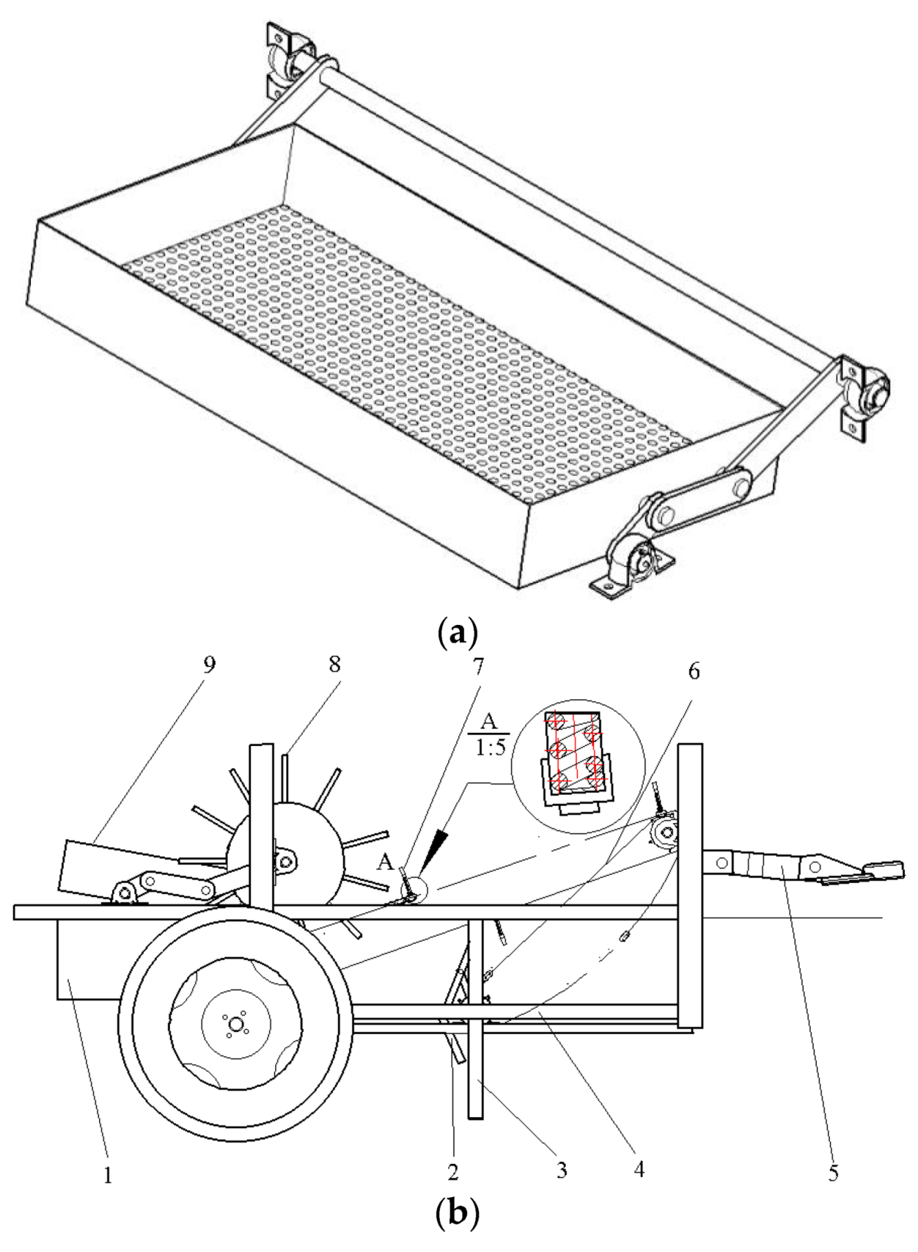
3. The Structure and Working Principle

The machine mainly consists of an ellipse gauge film-picking mechanism, finger clamping, transmission chain, four-link screen device, film collecting box, etc. The structural diagram is, as shown in Figure 2b, the positive view of the recovery machine, and Figure 2c is the top view of the recovery machine. The transmission system mainly adopts two-stage transmission. The tractor pulls the traction frame 5 to move forward along the film line. The rear output shaft of the tractor decelerates through the bevel gear transmission and drives the elliptical gauge film picking mechanism 2 to embed into the soil to pick up the residual film periodically. The longitudinal guide rail 3 controls the penetration depth of the elliptical gauge film picking mechanism 2. The transverse guide rail 3 controls the penetration depth and working angle of the elliptical gauge film picking mechanism 2. After two-stage chain drive deceleration, the clamping finger 7 on the conveying chain clamps the residual film of the elliptical gauge film picking mechanism 2 and transports it to the film stripping roller 8. Finally, the residual film is conveyed to the four-bar screen device 9 separating the cotton boll, cotton shell and sandrock, as shown in Figure 2a. Therefore, more impurities are thrown into the soil due to the action of gravity, and the residual film enters the film collecting box 1. The complete processes such as picking up, stripping and separation of membrane impurities are completed. After the multi-cycle reciprocating motion, the field residual membrane recovery operation is completed. In order to achieve effective residual film recovery, it is necessary to perform modeling and optimization on the parameters of the film picking mechanism.
In order to achieve effective residual film recovery, it is necessary to perform modeling and optimization on the parameters of the film picking mechanism. The major technical parameters of a new film-picking mulch film recovery machine with an impurity separation function are shown in Table 2.

3.1. The Design of the Film Picking Mechanism

Currently, the thickness of the mulch films, which are widely used in the Xinjiang region, is 0.008 mm, and the tensile strength of the film is lower than 0.010 mm~0.015 mm [27]. The ground surface is mixed with impurities such as plant stems, which make it difficult to collect the whole piece of the film. In order to achieve massive recovery and recycling of the mulch film, the paper designed a double-slider crank mechanism, which is used for film picking-up and intermittent film-cutting. As shown in Figure 3, the movement trajectory of the film pick-up mechanism is the forward and circular movement. The film picking mechanism in the design is made up of an upper rocker OB, down rocker BD, support bolt 3, etc. The connection way between upper rockers A and down rockers C is the pin joint. The supporting part relies on the coordination between the support bolt and bolt shank to adjust the dip angle of soil entry, and the adjusting range of the dip angle is 7~35°. The bolt shank is embedded in the down rocker to achieve the top length adjustment of the film picking rod, and the adjusting range is 30 mm~72 mm.
Set   AB = l 1 ,   BC = l 2   ,   CD = l 3   ,   BCD = θ
AB = l1; BC = l2; CD = l3; ∠BCD = θ
Then the horizontal and longitudinal displacements of terminal D are separate:
{ X D = ( l 2 + l 1 ) cos ( wt ) + l 3 cos ( wt + θ π ) Y D = ( l 1 l 2 ) sin ( wt ) l 3 sin ( wt + θ π )
Compared to the frame, the horizontal and longitudinal displacements of terminal D are separate:
{ X D = ( l 2 + l 1 l 3 cos θ ) 2 + ( l 3 sin θ ) 2 cos ( wt α ) Y D = ( l 2 l 1 l 3 cos θ ) 2 + ( l 3 sin θ ) 2 sin ( wt β )
Additionally, set
{ α = arctan ( l 3 sin θ l 2 + l 1 l 3 cos θ ) β = arctan ( l 3 sin θ l 2 l 1 l 3 cos θ ) R 1 = ( l 2 + l 1 l 3 cos θ ) 2 + ( l 3 sin θ ) 2 R 2 = ( l 2 l 1 l 3 cos θ ) 2 + ( l 3 sin θ ) 2
Compared to the inertial coordinate system, the horizontal and longitudinal displacements of terminal D are separate:
{ X D = R 1 cos ( wt α ) + kt Y D = R 2 sin ( wt β )
After obtaining the first and secondary derivatives of time on both sides of Equation (6), then the horizontal and longitudinal velocities of terminal D in the double-slider crank are separate:
{ V DX = wR 1 sin ( wt α ) + k V DY = R 2 cos ( wt β )
The horizontal and longitudinal accelerations are separate:
{ a DX = w 2 R 1 cos ( wt α ) a DY = w 2 R 2 sin ( wt β )

3.2. The Design of Clamping Conveying Mechanism

The clamping conveying mechanism is one of the key components to achieve residual film recovery, so its reliability and operation effects decide the recovery rate of residual films. Comparing the film conveying effects of embedded, horizontal and longitudinal clamping fingers, the horizontal is the best. The horizontal clamping fingers can significantly reduce the hard-to-disperse rate of impurities and film. If the distance of adjacent clamping fingers is too small, it is easy to cause secondary damage to residual films, and it is hard to disperse the film and impurities. If the distance is too large, the leakage phenomena of residual film picking will be serious. The schematic diagram of finger clamping movement in adjacent periods is as shown in Figure 4 and Figure 5. OC is the projectile motion of film impurity. O is the contact point in which the film stripping roller pulls away from the residual film from the clamping finger and is the origin of the Cartesian right-angle coordinate system. The horizontal direction is the x-axis. The vertical direction is the y-axis. xc is the horizontal displacement during film impurity ejection. yc is the vertical displacement during film impurity ejection. A is the critical contact point between the membrane picking mechanism and the soil. B is the contact point between the film picking mechanism and the clamping fingers.
Under the drive of the transmission system, the crank performs a clockwise rotational motion from A to B, and the film picking rod inserts into the soil from 1 (2) to pick up films and leave at 1 (2) conveying films. The area surrounded by the motion trajectory and the soil surface is the effective area of film picking-up. The onward speed is k. The rotational speed is w. The equivalent diameter is R2. We marked that the machine arrived at 1 at the time of t1, at 1 at the time of t2, at 2 at the time of t3 and at 2 at the time of t4. h is the depth between A point of membrane picking mechanism between the ground surface. X1 is the displacement of the implement in one cycle. X2 is the total displacement of the implement and film picking mechanism in two cycles. Δ X 11 is the horizontal displacement embedded in the soil of the picking film mechanism in the cycle. Δ X 12 is the suspended horizontal displacement of picking film mechanism in the cycle. Δ X 22 is the horizontal displacement embedded in the soil of the picking film mechanism in the next cycle.
The condition of the film picking machine to miss picking up films is:
Δ X 11 X 0 0
where:
X 0 = the forward displacement of the film picking mechanism separating from the soil in one cycle.
Place Equation (9) into Equation (4), then:
k ( 5 π 2 arcsin ( R 2 2 h R 2 ) ) π w 2 h R 2 2 h h 2 0
{ N 2 cos φ + N 1 = m gcos φ T 2 = m gsin φ + T 1 + μ N 1 N 2 sin φ f 1 = μ N 1
where:
  • T 1 = the pulling force of film picking mechanism on residual film (N);
  • T 2 = the pulling force of clamping finger on residual film (N);
  • N 1 = the supporting force of clamping finger on residual film (N);
  • N 2 = the supporting force of film picking mechanism on residual film (N);
  • m = the mass of the residual film (Kg);
  • f = the friction between residual film and impurities (N);
  • g = the acceleration of gravity (m/s2);
  • μ = the friction coefficient between residual film and impurities;
  • φ = angular separation between straightening direction and horizontal direction of the residual film.
From Equation (11), we can establish that the compulsory condition of residual films obtaining secondary damage in the tangential direction is:
T 2 m gsin φ T 1 μ N 1 N 2 sin φ 0
In the radial direction, the resultant force to bear for residual films is:
F Resultant   force = mw 2 R > m gcos φ N 1 N 2 cos φ
where
  • R = curvature radius of the film picking mechanism in a non-uniform circular motion (m);
  • φ = the longitudinal included angle formed by gravity and the clamping finger.
In the process of film impurity separation, due to gravity, residual films fall into the four-link screen device. The residual films, mixed with impurities, will perform variable speed circular motion after being released from clamping fingers. The motion velocity of residual films and impurities could be regarded as the same. Residual films will perform variable speed circular motion taking R as the radius in the film picking process and performing low-speed parabolic motion after moving out of the ground. Moreover, the air resistance is proportional to velocity, which means the air resistance is:
F a = kv
where
  • Fa = the air resistance (N);
  • k = the resistance coefficient (N·s/m);
  • v = the velocity of residual films (m/s).
The linear velocity of residual films equals the linear velocity of clamping fingers when residual films leave clamping fingers, which is:
v 1 = π Rn 1 z 1 30 z 2
where
  • z1 = the tooth number of spindle sprocket wheels of the film picking machine;
  • n 1 = spindle speed of the film picking mechanism (r/s).
From Equation (13) to Equation (15), we can establish that, in the process of film impurity separation, the spindle’s critical minimum rotational velocity of the film picking machine is:
n 1 > z 2 m gcos φ N 1 N 2 cos φ mR 2 π z 1
where
  • n 1 = the spindle’s rotational velocity of the film picking machine, r/s;
  • z 2 = the tooth number of sprocket wheels.
The curvature radius of the film picking machine performing the circular motion is:
R R = | 1 + ( 1 + ( d y d x ) 2 ) 3 / 2 d 2 y d x 2 | = | 1 + ( 1 + ( R 2 cos ( w t β ) R 1 cos ( w t α ) + k ) 2 ) 3 / 2 R 2 sin ( wt β ) ( R 1 w sin ( wt α ) + k ) R 1 3 w 4 cos 3 ( wt α ) ( w R 1 R 2 cos ( w t α ) cos ( w t β ) R 1 3 w 4 cos 3 ( w t α ) ) |
Based on Taylor series expansion of Equation (17), after collation, we can obtain:
R = l η sin ( wt α ) sin ( wt β ) ρ cos ( wt α ) cos ( wt β ) × R 2 2 w 3 ( wt α ) 2 R 1 ( wt α )
where
  • l = the proportional coefficient;
  • η = the sinusoidal coefficient;
  • ρ = the cosine coefficient.
Films and impurities perform parabolic motion after releasing from clamping fingers. The motion trajectory decides the film-striping effects of the stripping roller. After performing kinematics analysis on this process, the working parameters of the machine can be determined. Establish a Cartesian rectangular coordinate system with the projectile point as the origin of the coordinates. Then, the force condition of films and impurities after being projected is shown in Figure 3 [28].
{ v x = v 2 e ε t m v y = ( v 2 - mg ε ) e ε t m + mg ε
where
  • v2 = the initial velocity of films and impurities being projected (m/s);
  • vx = the horizontal vector of the initial velocity (m/s);
  • vy = the vertical vector of the initial velocity (m/s);
  • t = the period time from films and impurities being projected to touching the stripping roller (s);
  • ε = the damping coefficient.
Films and impurities are under the interaction of air resistance and gravity. Through the integration with the parameter of Equation (19), we can establish that the horizontal and longitudinal displacements of films and impurities from being projected to touching the stripping roller are:
{ x c = 0 t v 2 e ε t m dt = v 2 m ε ( e ε t m 1 ) y c = 0 t ( ( v 2 m g ε ) e ε t m + mg ε ) dt = m ε [ ( v 2 m g ε ) ( e ε t m 1 ) + mgt ε ]
v 3 = π dz 1 n 1 60 z 3
where
  • v3 = the velocity of the stripping roller (m/s);
  • d = the pitch circle diameter of the sprocket wheel;
  • z3 = the tooth number of the sprocket wheel on the film-stripping roll shaft.
The film-stripping mode is the reverse film-stripping of the stripping roller, and the necessary condition of normal film-stripping is:
v = v x 2 + v y 2     v 3
By setting the simultaneous equation of Equations (21) and (22), we can establish that the critical maximum of the spindle’s rotational velocity of the film picking machine is:
n 1     60 z 3 v 3 π dz 1
From the above analysis, when the adjacent winding lines overlap, the leakage phenomenon is avoidable and periodic film-picking can be realized during the residual film recycling process. The film-picking mechanism and the clamping conveying mechanism should be in a reasonable proportion. In order to avoid secondary damage to the residual film, the minimum tensile strength to bear in the radial direction should be less than the horizontal fracture strength of residual films. The necessary conditions of film impurity separation and normal film-stripping could be the theoretical basis of the design of the film-picking mechanism.
Based on the operation requirements of residual film recovery, the onward velocity of the residual film recycling mechanism should be 2.2 km/h~5.0 km/h, and the rotational speed of the film-picking mechanism is 1.5 r/s~2.8 r/s. Through the analytical method and the critical condition of secondary damage of residual film, the following values can be determined. The spacing between fingers is 291.2 mm. The maximum tensile angle of the finger is 12°. The angle between the conveyor chain and the horizontal plane is 28°.

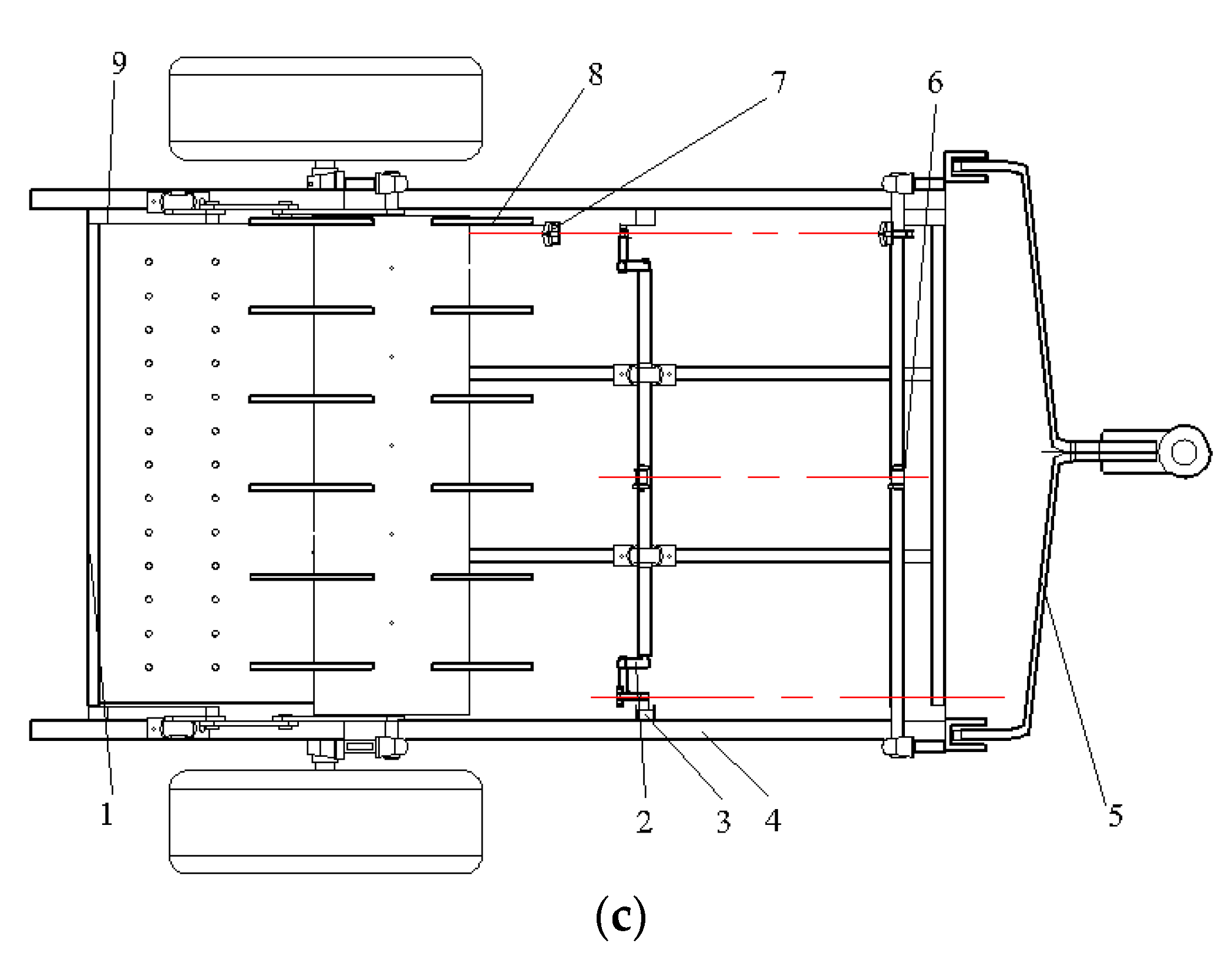
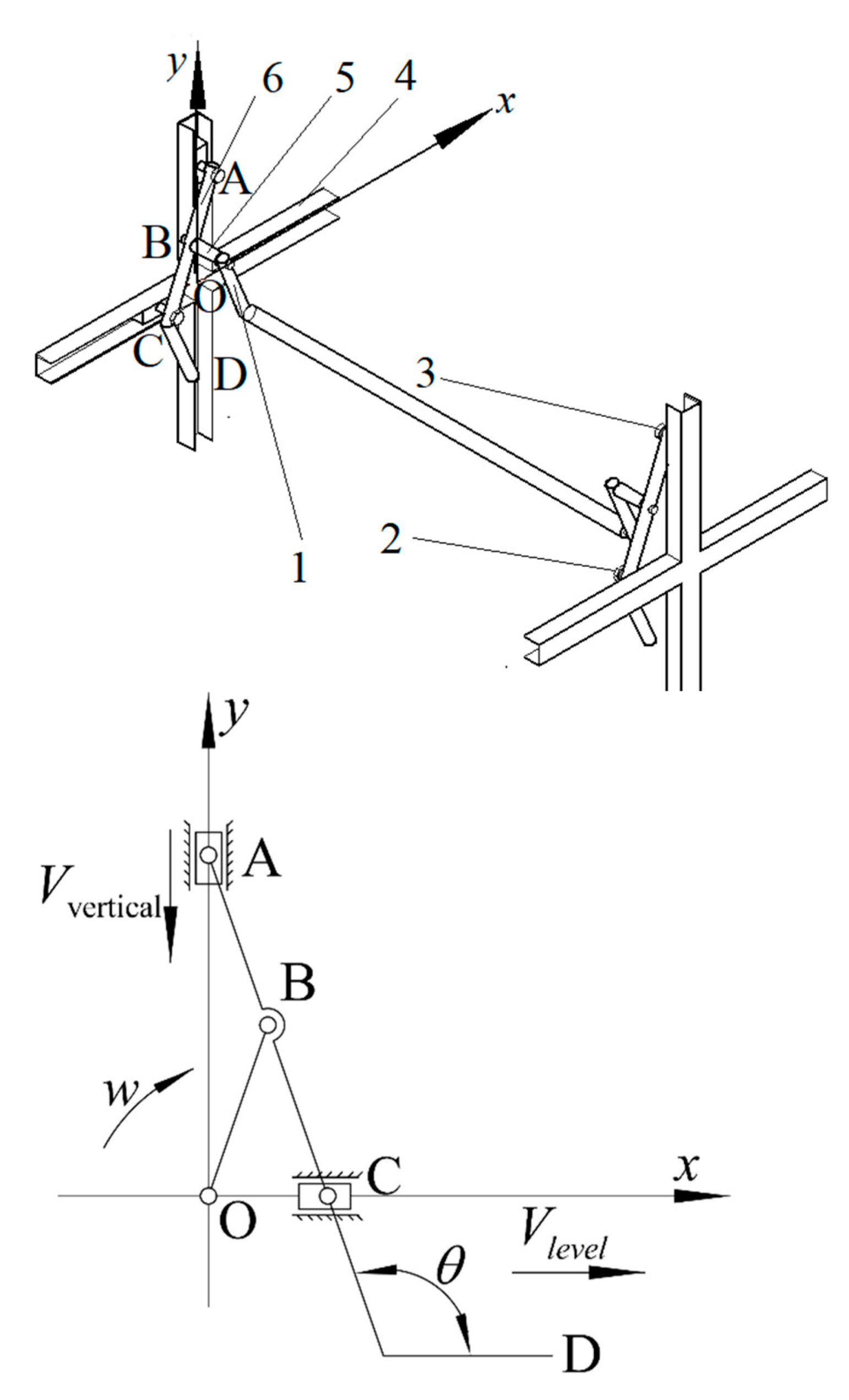
3.3. The Analysis of the Film-Picking Mechanism

3.3.1. The Analysis of the Film-Picking Mechanism

After cotton straw recovery, marginal films are difficult to be recycled because of the following reasons. The residual films are detained in the soil for a long time and collapsed by impurities such as straw, stems, leaves and weeds. The residual films were crushed by the soil. The membrane-soil model equivalent is set to a plane with fixed sides, rotating around the center. Residual films do not show any stiffness without stress. After applying suitable pre-stress on the film to make it show enough stiffness, the deformed shape of the unit and the constraint graph in boundary condition can be determined, as shown in Figure 6. The film unit does not possess the properties of anti-bending and anti-compression. The initial form is set to under with constraints. After applying initial stress and iterative calculation, the derivation proceeds under the equilibrium condition. The SHELL181 shell element is adopted to establish the structure of residual films, and the film material is defined as in-plane isotropic material. The density of mulch films is 9.2 × 10² kg/m3. The elastic modulus is 6.21 × 10⁵ Pa. The Poisson ratio is 0.35. Fixed constraints are made in x, y, z directions and in the displacement of radial boundary lines in x and z directions. The paper added contour maps of the displacement field and the Mises equivalent stress distribution, which are as shown in Figure 7 and Figure 8. Residual errors are all less than the convergence criteria. The maximum displacement is 1.62372 mm. The dangerous stress value is 0.401876 Pa, and it acts on the point (0, 11.3894, −5). The displacement field is the largest at the center and decreases by a constant gradient along the circumference. The minimum deformation value is 0.144704 mm, and the maximum deformation is less than the allowable deformation of residual films after harvest.

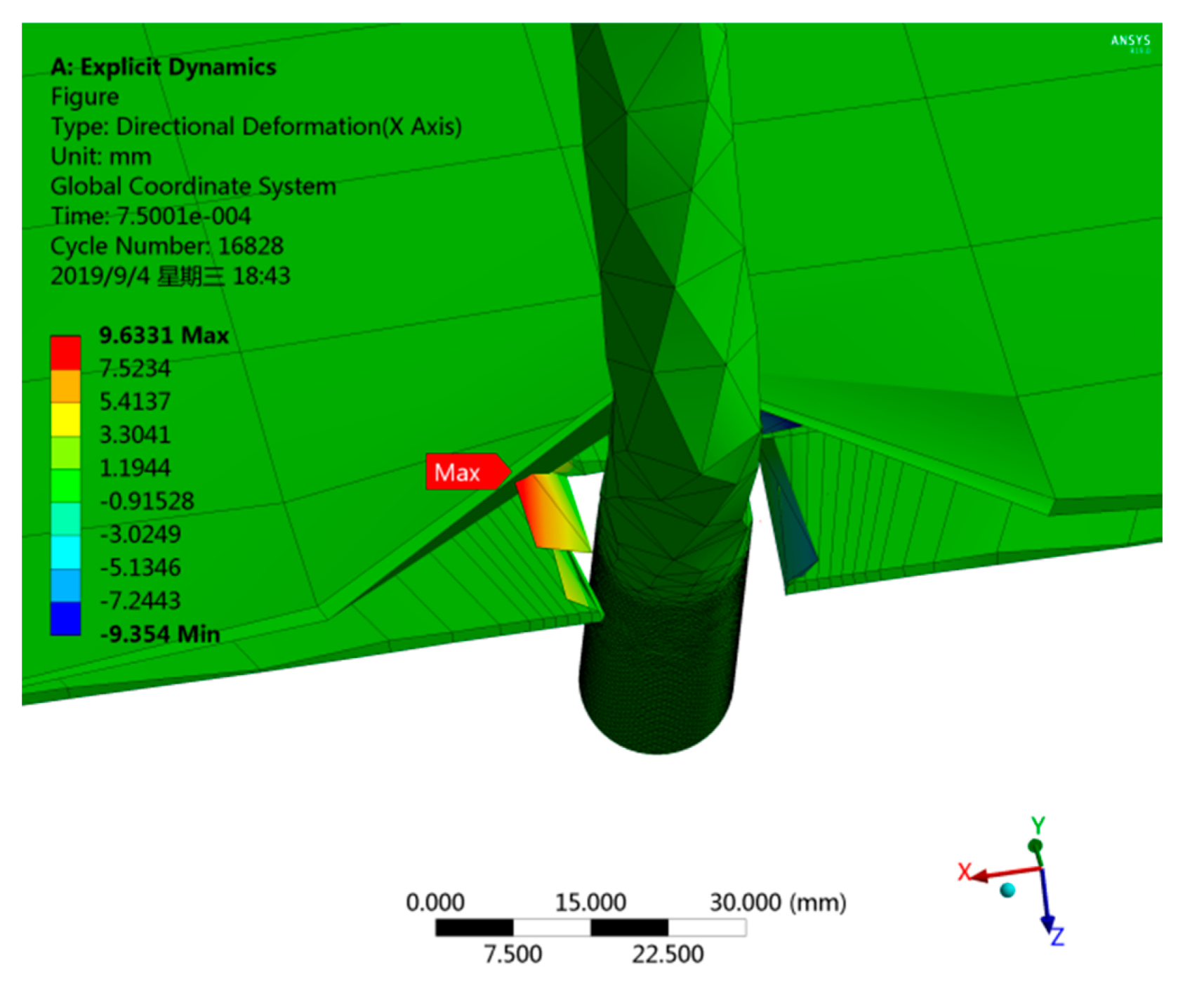
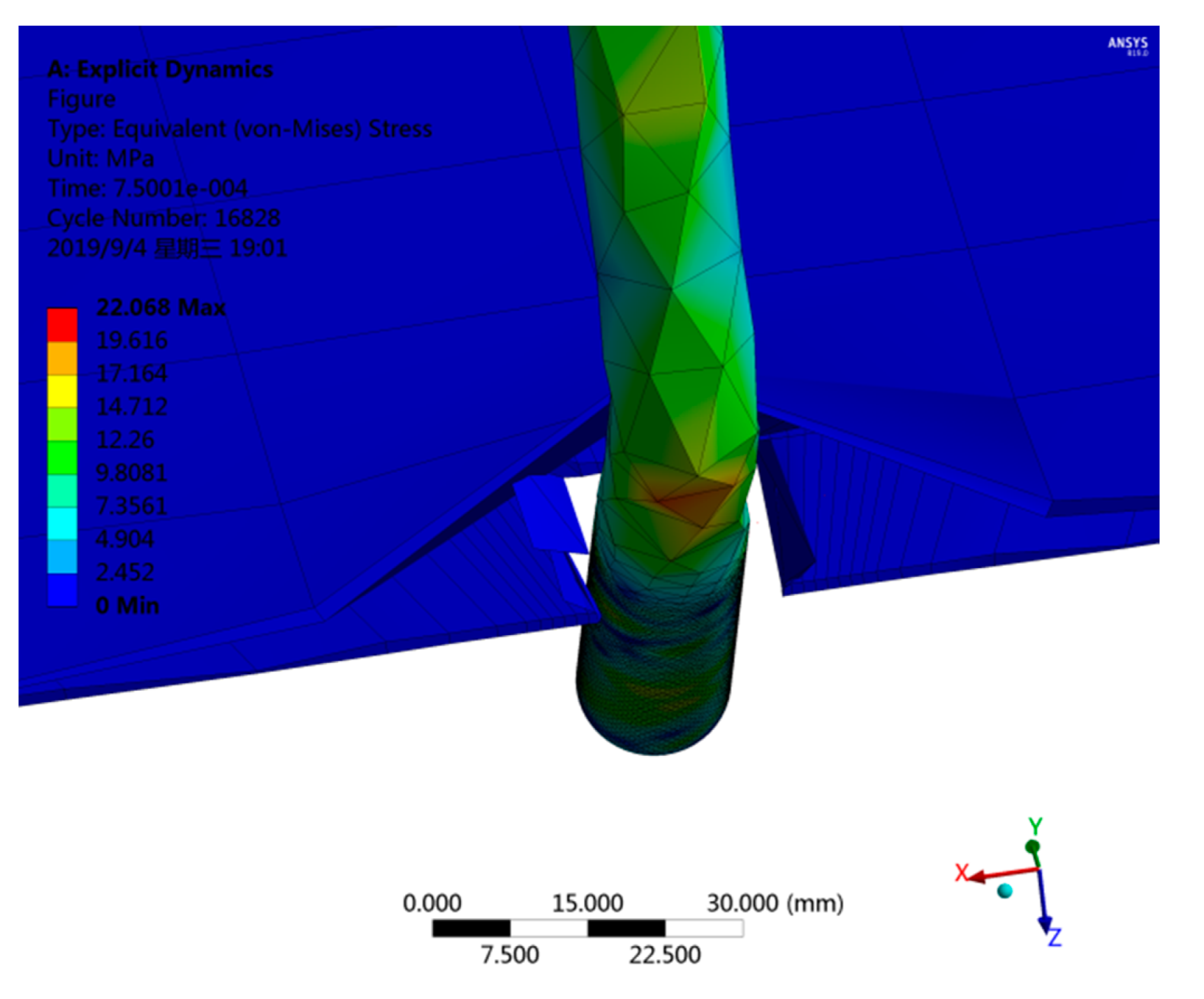
3.3.2. The Dynamic Simulation Analysis of the Film-Picking Process
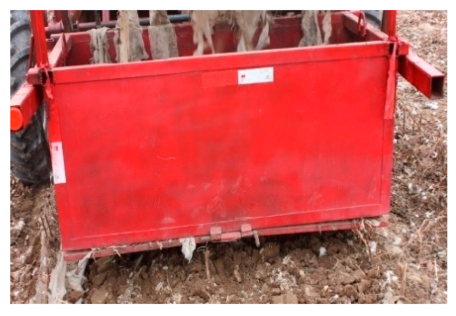
The film-picking mechanism is one of the key components of the residual film recycling mechanism. The paper uses the Workbench/explicit dynamics module to analyze the nonlinear dynamics problems of the film-picking process. The material of the film-picking machine is defined as 65 Mn steel, and the density is 7850 kg/m3. The elastic modulus is 2.1 × 10¹¹ Pa, and the Poisson ratio is 0.34. The soil type is sandy soil, and its density is 2600 kg/m3. The elastic modulus is 1 × 10⁷ Pa, and the Poisson ratio is 0.38. The thickness of the mulch film is 0.008 mm. The contact manners between the soil and the film-picking machine and between the film-picking machine and the mulch film are both frictional contacts. The contact manner between the soil and the mulch film is Rough contact. The static friction coefficient between the soil and the film-picking machine is 0.62, and the dynamic friction coefficient is 0.051. The static friction coefficient between the film-picking machine and the mulch film is 0.57, and the dynamic friction coefficient is 0.048. Based on the actual operation in the actual residual film recycling process, the horizontal velocity of the film picking machine is 3.8 km/h, the angular velocity is 5.1 rad/s and the treatment time is 0.018 s. The deformation diagram and the stress diagram of the film-picking machine are as shown in Figure 9 and Figure 10. The operation of the film-picking machine contains two processes, which are inserting into the soil to pick up films and leaving the soil with films. The deformation value in the end and corner of the film-picking machine are the largest (the amplification coefficient is 10). The actual maximum deformation value is 0.96331 mm, and the actual maximum stress value is 2.2068 Mpa. When the mulch film, soil and straws attrite and rub with each other, it is easy to produce electrostatic. This causes a higher impurity rate, and the damage rate of the mulch film is also increased significantly.
Establish the 3D parametric assembly model of the double-slider crank film-picking machine, as shown in Figure 11. Save the model as Parasolid (.X_T) and import it into Adams/view. Add the following constraints to the physical parameters mentioned in Section 3.2 under the connector module [29]. The connection between crank and ground, rocker and the upper and down sliders is rotating. The crank, upper, down sliders and ground, is translational. The rotary driving angular velocity between crank and ground is 2.2 rad/s. The movement driving velocity is 1200 mm/s. Increase the simulation run velocity and decrease Lagrange iteration times [30]. Keep one double-slider crank film-picking machine. Set the simulation time as 1 s and the length as 250 steps.
Set mark points MARKER7 and MARKER8 at the corner and end of the rocker. A series of kinematics results are output from Adams/Postprocessor. Figure 12a is the path curve of marked points (MARKER7 and MARKER8). Figure 12b is the curve of the horizontal displacement of the marked point (MARKER7 and MARKER8) with time. Figure 12c is the curve of the vertical displacement of the marked point (MARKER7 and MARKER8) with time. Figure 13 is the curve of the linear velocity of the marked point with time.
As shown in Figure 12a, The operation depth of the film-picking machine is 110 mm~115 mm, which meets expected requirements. The effective picking area surrounded by the corner (MARKER7) and the end of the rocker (MARKER8) is 8211 mm2. As shown in Figure 12b, there is no variable length at entry and departure points of the single film-picking machine to remove the leakage phenomena. The difference of horizontal displacement between MARKER7 and MARKER8 is 0.311 m. According to design requirements, it can avoid secondary damage caused by miss-picking and the film picking mechanism. As shown in Figure 12c, during 0 s~0.17 s, the film-picking machine is embedded into the soil, and the residual film is depressed extruded by the soil. During 0.17 s~0.38 s, the film-picking machine leaves the soil with films. (The clamping fingers clamps the residual film at the end of the film picking mechanism). Under the action of inertia, films and soil continue the variable circular motion in 0.38 s~0.64 s. In 0.38 s, the vertical coordinates of the corner and end of the film-picking machine are the same. The soil falls due to gravity. The residual film needs to overcome its gravity, the fraction and cohesive force of the soil and air resistance. Upon previous experiments results, when the end speed of the film-picking mechanism is greater than 1.51 m/s in unit volume, the residual film continues the variable-speed circular motion. At 0.8 s, the clamping conveyor clamps the residual film to complete film picking and conveying.

4. Field Test

4.1. Test Conditions

The test location is the Eighth Division of Xinjiang Production and Construction Corps, China. The average flatness of the test field is between −11.7 mm and 23.6 mm. The moisture content of the soil is 16.8~19.7%. Drip tapes were recycled. The cotton plant mode is one film covering six rows, and the film-covering time is 160d. The machine is pulled by a John Deere tractor.

4.2. Test Design and Methods

Upon previous experiments, the main factors influencing the operation result are the onward speed x1, the working angle of the film-picking machine x2 and the depth into the earth of the machine x3. The response indexes are the recovery rate of residual films D, the damage rate E and the release rate N; these indexes are tested according to the Chinese Standard GB/T 25412-2010 Residual Film Recycling Machine. The paper adopts a central composite quadratic regression rotatable orthogonal experiment and full implementation action [31,32]. There are 20 experimental sites in total, which include eight two-level tests, six star and six zero-level tests [33]. The length of the star arm is 1.682. The coding level of test factors is shown in Table 3.

4.3. Test Indicators

In the test recycling process, recovery rate and release rate reflect the overall residual film recycling condition and the working performance of the machine. Damage rate directly influences the recycling and reuse result of residual films [34,35]. The test indicators are drafted as follows. The recovery rate D is defined by Equation (24), damage rate E by Equation (25) and release rate N by Equation (26).
D = m e m c + m d + m e
E = ( s 1 m e m 0 s 0 ) s 1
N = 1 m f m e
where
  • m = the flattening gross mass of residual films from the film collecting box (g);
  • mc = the mass of residual films which fall in the testing area (g);
  • me = the mass of residual films which winds in the film-picking machine and clamping conveyor (g);
  • mf = the mass of residual films in the film collecting box (g);
  • m0 = the per unit area mass of unused films (g);
  • s0 = the unit area of unused films (m2);
  • s1 = the flattening gross area of residual films from the film collecting box (m2).
In the testing area, 15 measuring fields are selected randomly, where the procession length of the machine is 18 m. In each measuring field, the measuring position is selected randomly, whose length is 150 m and width is 80 m. Four measuring points are randomly picked in the range of 1/6 diagonal of the four corners. The intersection point is added as the first five measuring points. Then another five testing points are randomly selected in the area near but not overlapping with the previous five points as the testing points after the operation.
The test scheme and results are as shown in Table 4.

4.4. The Analysis and Optimization of the Test Results

4.4.1. The Establishment and Significance Test of the Regression Equation

With the help of the test design and data processing software, Design Expert 8.0.6, the fitting analysis of the quadratic polynomial regression was applied to the results in Table 2, and the optimal parameter solution was obtained. The regression equations for the recovery, damage and film removal rate to the working angle, buried depth of pick-up mechanism and the working angle of clamping conveyor were established, respectively. The regression equation was analyzed by variance, and the result is shown in Table 5.
D = 90.70 + 1.70 x 1 + 3.22 x 2 + 2.48 x 3 + 2.16 x 1 x 2 1.86 x 1 x 3 + 2.24 x 2 x 3 3.17 x 1 2 5.43 x 2 2 6.05 x 3 2
E = 19.68 0.62 x 1 5.92 x 2 5.07 x 3 0.49 x 1 x 2 0.14 x 1 x 3 + 0.29 x 2 x 3 + 1.31 x 1 2 + 3.33 x 2 2 + 3.18 x 3 2
N = 75.74 1.06 x 1 + 2.71 x 2 1.92 x 3 1.65 x 1 x 2 + 1.98 x 1 x 3 2.55 x 2 x 3 + 1.59 x 1 2 + 1.84 x 2 2 + 2.60 x 3 2
In the model, the P of recovery rate, damage rate and release rate are all less than 0.01, which indicates a highly significant regression model. The values of lack of fit P are all more than 0.05. The decision coefficient of Model D is 0.95797, Model E is 0.96221855 and Model N is 0.866, which indicates a high fitting degree. Therefore, the above parameters can be optimized by the model.
The regression terms x 2 , x 3 , x 1 2 , x 2 2 and x 3 2 in Model D have a great significant influence on the recovery rate. x 1 , x 1 x 2 and x 2 x 3 have a significant influence on the recovery rate. x1x3 has no significant influence on the recovery rate. x 2 , x 2 2 and x 3 2 in Model E have a great significant influence on the damage rate. x 1 2 has a significant influence on the damage rate. x 1 , x 1 x 2 , x 1 x 3 and x 2 x 3 have no significant influence on damage rate. x 2 and x 3 2 in Model N have a great significant influence on the recovery rate. x 3 , x 2 x 3 , x 1 2 and x 2 2 have a significant influence on the damage rate. x 1 , x 1 x 2 and x 1 x 3 have no significant influence on damage rate. After the elimination of non-significant factors in these three regression models, the regression equations of all factors are as follows:
D = 90.70 + 1.70 x 1 + 3.22 x 2 + 2.48 x 3 + 2.16 x 1 x 2 + 2.24 x 2 x 3 3.17 x 1 2 5.43 x 2 2 6.05 x 3 2
E = 19.68 5.92 x 2 + 1.31 x 1 2 + 3.33 x 2 2 + 3.18 x 3
N = 75.74 + 2.71 x 2 1.92 x 3 2.55 x 2 x 3 + 1.59 x 1 2 + 1.84 x 2 2 + 2.60 x 3 2

4.4.2. The Analysis of the Influencing Factors’ Influence on Performance Effect

The single factor’s influence weight on the regression model is represented by the weight coefficient L [36]. The larger L, the higher degree of the influence weight of the factor on the model will be. After calculating Equations (33) and (34), the influence weight order of all factors on the recovery rate is as follows. The depth into the soil of the film-picking machine is greater than the working angle of the clamping conveyor machine greater than the working angle of the film-picking machine. The influence weight order of all factors on the damage rate is as follows. The depth into the soil of the film-picking machine is greater than the working angle of the film-picking machine greater than the working angle of the clamping conveyor machine. The influence weight order of all factors on the release rate is as follows. The depth into the soil of the film-picking machine is greater than the working angle of the clamping conveyor machine greater than the working angle of the film-picking machine. The calculation results are as shown in Table 6.
Φ = { 0   F 1 1 1 F     F > 1
L x j = Φ x j + Φ x i x j 2 x 1 , x 2 , x 3 + Φ x j 2
where
  • F = the value of the variance analysis on the regression model;
  • Φ = the weight coefficient of the regression term to F and L x j is the weight coefficient of all factors.

4.5. The Analysis of All Interaction Factors to Response Index

4.5.1. The Analysis of All Interaction Factors to the Residual Film Recovery Rate

Figure 14a–c shows the response surface diagram of interaction factors on residual film recovery rate. x 1 represents the working angle of the film picking mechanism. x 2 represents the penetration depth of the film picking mechanism. x 3 represents the working angle of the clamping conveyor. Figure 14a shows the response surface diagram of the interaction between the working angle and the depth to the residual film recovery rate D. The working angle of the clamping and conveying device is at the central level ( x 3 = 44°). The residual film recovery rate increases at first then decreases with the increase in the working angle and the depth into the soil of the film-picking machine. The depth into the soil of the film-picking machine has a more significant influence on the residual film recovery rate. Figure 14b shows the response surface diagram of the interaction between the working angle of the picking mechanism and the clamping conveyor on the residual film recovery rate D. The depth of the picking mechanism is at the center level ( x 2 = 55 mm). The residual film recovery rate increases at first then decrease. The residual film recovery rate increases with the increase in the working angle of the film-picking machine, and it increases at first then decreases with the increase in the working angle of the clamping conveyor. The working angle of the clamping conveyor has a more significant influence on the residual film recovery rate. Figure 14c shows the response surface of the interaction between the soil depth of the pick-up mechanism and the working angle of the clamping conveyor on the residual film recovery rate D. The working angle of the pick-up mechanism is at the central level ( x 1 = 32°). The residual film recovery rate increases at first then decreases with the increase in the depth into the soil of the film-picking machine and the working angle of the clamping conveyor. The depth into the soil of the film-picking machine has a more significant influence on the residual film recovery rate.
It can be seen from the response index values in Figure 14a–c that the variation law of all factors to response index values matches with the result of the variance analysis in regression Model D. The residual film recovery rate will be higher if the working angle and depth into the soil of the film-picking machine and the working angle of the clamping conveyor are larger. The main reason is that the effective area will be larger if the working angle and the depth of the soil are larger. The effective area is where is scanned by the single circular motion in a period of time. Then the leakage phenomenon is avoidable in the residual film-picking process. If the depth into the soil is too large, the resistance to bear for the film-picking machine will be too large, which is easy to produce electrostatic. Moreover, the film-picking machine will be easy to wind with residual films and impurities, which brings difficulties for later film impurity separation. The more times the clamping conveyor clamps films, the probability that the residual films in the film-picking machine are removed from the clamping conveyor will be lesser in the conveying process. The working angle of the clamping conveyor machine should not be too large. Otherwise, it will cause the back-drawing of residual films in the film-releasing process.

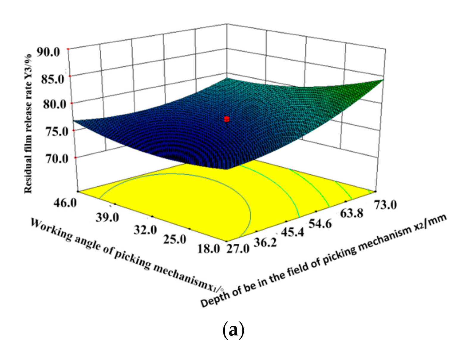
4.5.2. The Analysis of All Interaction Factors to the Residual Film Release Rate

Figure 15a–c shows the response surface diagram of interaction factors on residual film release rate. As shown in Figure 15a, the working angle and the depth into the soil to the residual film release rate N. The working angle of the clamping conveyor is at the central level ( x 3 = 44°). The residual film release rate decreases at first then increases with the increase in the working angle of the film-picking machine. The residual film release rate increases with the increase of the depth into the soil of the film-picking machine. The depth into the soil of the film-picking machine has a more significant influence on the residual film release rate. Figure 15b shows the response surface diagram of the interaction between the working angle of the film-picking machine and the clamping conveyor to the residual film release rate N. The depth into the soil is at the central level ( x 2 = 55 mm). The residual film release rate decreases at first then increases. The residual film release rate decreases with the increase in the working angles of the film-picking machine and the clamping conveyor. The working angle of the clamping conveyor has a more significant influence on the residual film release rate. Figure 15c shows the response surface diagram of the interaction between the depth into the soil and the working angle of the clamping conveyor to the residual film release rate N. The working angle of the film-picking machine is at the central level ( x 1 = 32°). Residual film release rate decreases at first then increases with the increase in the working angle of the clamping conveyor. The residual film release rate increases with the increase in the depth into the soil of the film-picking machine. The depth into the soil of the film-picking machine has a more significant influence on the residual film release rate.
From the response index values in Figure 15a–c, it can be seen that the variation law of all factors to response index values matches with the result of the variance analysis in regression Model N. The residual film release rate will be higher if the working angle of the film-picking machine is smaller and the depth into the soil and working angle of the clamping conveyor are larger. The main reason is that the contact times are more between the clamping conveyor if the working angle is smaller and the depth into the soil is larger. The stripping roller will be in a single circular motion in periods, and the release rate will be higher. This helps to remove too many residual films winding with the clamping conveyor on the surface. If the depth into the soil is larger, the clamping conveyor machine can clamp residual films in order, which helps remove residual films congested in clamp fingers.

4.6. Parameter Optimization

In the residual film recycling process, film-picking and film-releasing are both of great importance. The residual film recovery rate and release rate are important parameters to evaluate the quality of residual film recovery. The residual film damage rate is the key reference index influencing the recycling and reuse of residual film. Considering the actual operation requirements of the machine, the weight coefficients of residual film recovery rate and release rate are both 5/12, and the weight coefficient of damage rate is 1/6. With the help of the optimization device of Design-Expert, apply the iterative solution on the influencing factors of the residual film recovery rate, damage rate and release rate. Optimum parameters are as follows. The working angle of the film-picking machine is 27.31°. The depth of the soil is 73.0 mm. The working angle of the clamping conveyor machine is 38.33°.
In order to verify the influencing effect of all factors on residual film recovery rate and release rate after optimization, the paper drafted the optimal values of the working angle of the film-picking machine as 27.3°, the depth into the soil as 73.0 mm and the working angle of the clamping conveyor as 38.3°. Moreover, the paper made a contrast analysis between the actual and optimal response indexes, and the relative errors are both less than 1.5%.
The research team of the paper conducted the field test five times in some certain testing field at Shihezi City, Xinjiang, China, as shown in Figure 16. Based on the calculation of Equations (24)–(26), the residual film recovery rate is 92.5%, and the release rate is 87.6%. After comparing with the optimized results, the recovery rate as 93.9% and the release rate as 89.3%, the relative errors are both less than 1.5%. The test result indicates the reliability of the optimal model.

5. Discussion and Conclusions

Current machines have problems such as the complex machine structure, low reliability and poor recovery results. The paper has designed a film-picking with an impurity separation residual film recovery machine. It mainly consists of horizontal and longitudinal film-cutting devices, double-slider crank, film-conveying device, four-link screen, film collecting box, etc. According to the residual film recycling conditions and the motion trajectory of the film picking mechanism, the motion trajectory of the film picking mechanism is indicated by the oblique ellipse equation (R1 is the long half axis and R2 is the short half axis in the equation). By combining the analysis of the force of clamping conveying mechanism, the mechanical models are obtained, such as join forces of film, the acting force of clamping fingers on residual film, the acting force between film picking mechanism and residual film, the friction coefficient between residual film and impurities, and the included angle between straightening direction and horizontal direction of the residual film. The critical conditions of missing-picking of the film-picking mechanism are assured. The relationship among short half shaft, soil height, the rotational velocity of the crank, and the forward velocity of machines are verified. According to the necessary conditions for the secondary damage of the residual film, the acting force between clamping fingers and residual film, the acting force between film picking mechanism and residual film, the relationship of the friction coefficient between the residual film and impurities and necessary conditions for film stripping are obtained. The parameters of key components are assured. The recovered residual film is washed and dried, and the average thickness is 0.0053 mm measured by the indirect measurement method.
The paper adopts a central composite quadratic regression rotatable orthogonal experiment and drafts an implementation plan. It also applies the fitting analysis of the quadratic polynomial regression and obtains the optimal parameter solution. The regression equations of recovery rate, damage rate and release rate to the working angles of the film-picking machine and the clamping conveyor and the depth into the soil of the film-picking machine are established separately, and the variance analysis on these regression equations are conducted. The influence weight order of all factors on the recovery rate is as follows: the depth into the soil of the film-picking machine is greater than the working angle of the clamping conveyor machine greater than the working angle of the film-picking machine. The influence weight order of all factors on the damage rate is as follows: the depth into the soil is greater than the working angle of the clamping conveyor machine. The influence weight order of all factors on the release rate is as follows: the depth into the soil of the film-picking machine is greater than the working angle of the clamping conveyor machine greater than the working angle of the film-picking machine.
The paper applies the iterative solution on the influencing factors of the residual film recovery rate, damage rate and release rate and obtains the optimum parameters as follows: the working angle of the film-picking machine is 27.31°, the depth into the soil is 73.0 mm and the working angle of the clamping conveyor machine is 38.33°. Compared with the optimized results, the recovery rate as 93.9% and the release rate as 89.3%, the relative errors are both less than 1.5%. The test result indicates the reliability of the optimal model.

Author Contributions

Conceptualization, J.D., S.L., X.B. and G.W.; methodology, X.B., J.W., W.W. and N.T.; software, J.D., S.L. and X.B.; validation, J.D., S.L. and X.B.; formal analysis, J.D., S.L. and X.B.; investigation, J.D., S.L., X.B. and W.W.; resources, X.B. and N.T.; data curation, J.D., G.W. and J.W.; writing—original draft preparation, J.D. and S.L.; writing—review and editing, J.D., S.L., X.B., J.W., W.W. and N.T.; supervision, X.B. and J.W.; project administration, G.W., W.W. and N.T; funding acquisition, X.B. and J.W. All authors have read and agreed to the published version of the manuscript.

Funding

This work was financially supported by the research was supported by the National Natural Science Foundation of China (Grant No.51465050).

Institutional Review Board Statement

Not applicable.

Informed Consent Statement

Not applicable.

Data Availability Statement

All relevant data presented in the article are according to institutional requirements and, as such, are not available online. However, all data used in this manuscript can be made available upon request to the authors.

Conflicts of Interest

The authors declare no conflict of interest.

References

  1. Mahajan, G.; Sharda, R.; Kumar, A.; Singh, K.G. Effect of plastic mulch on economizing irrigation water and weed control in baby corn sown by different methods. Afr. J. Agric. Res. 2007, 2, 19–26. [Google Scholar]
  2. Jiang, X.J.; Liu, W.J.; Wang, E.H.; Zhou, T.Z.; Xin, P. Residual plastic mulch fragments effects on soil physical properties and water flow behavior in the minqin oasis, northwestern China. Soil Tillage Res. 2017, 166, 100–107. [Google Scholar] [CrossRef]
  3. Ning, S.R.; Zuo, Q.; Shi, J.C.; Wang, S.; Liu, Z.S. Water use efficiency and benefit for typical planting modes of drip-irrigated cotton under film in Xinjiang. Trans. Chin. Soc. Agric. Eng. 2013, 29, 90–99. [Google Scholar]
  4. Meng, H.W.; Li, J.J.; Wang, N.Y.; Kan, Z. The design of the comb-tooth drum type residual film recycling machine. J. Agric. Mech. Res. 2021, 34, 145–148. [Google Scholar]
  5. Niu, Q.; Chen, X.G.; Ji, C. Experiment and optimal design of a collection device for a residual plastic film baler. Front. Agric. Sci. Eng. 2015, 2, 347–354. [Google Scholar] [CrossRef] [Green Version]
  6. Parish Richard, L.; Bracy Regina, P. Removal and collection of plastic mulch. ASAE Annu. Int. Meet. 2000, 1, 2267–2274. [Google Scholar]
  7. Chrysler, R.W. Apparatus for Removing Plastic Film from Raised Plant Beds. U.S. Parent No. 4796711, 10 January 1989. [Google Scholar]
  8. Rocca, A.R. Plastic Mulch retriever for Use by e.g., Faarmer. Australia Patent No. WO20090776729-A1, 10 June 2014. [Google Scholar]
  9. Ma, S.; Zhang, X. Design and Experiment of Side of Used Plastic Film Collector Machine. Agric. Eng. 2012, 28, 73–75. [Google Scholar]
  10. Abdureyim, I.; Hamdulla, A.; Tursun, M. FEM Analysis and Optimization Design of a Plastic Film Cutting Machine Tool Rest Structure. Adv. Mater. Res. 2008, 33–37, 1393–1398. [Google Scholar] [CrossRef]
  11. Zhang, H.M.; Yan, L.M.; Chen, X.G. Simulation and test of film surface cleaning roller of residual film collector. Int. Agric. Eng. J. 2019, 28, 257–267. [Google Scholar]
  12. Yang, S.M.; Chen, X.G.; Yan, L.M. Performance of three different spades for residual plastic film recycling machine. Appl. Eng. Agric. 2020, 36, 187–195. [Google Scholar] [CrossRef]
  13. Van Der Meulen, E.S.; Nol, L.; Cammeraat, L.H. Effects of irrigation and plastic mulch on soil properties on semiarid abandoned fields. Soil Sci. Soc. 2006, 70, 930–939. [Google Scholar] [CrossRef] [Green Version]
  14. Horodytska, O.; Valdés, F.J.; Fullana, A. Centrifugal dewatering performance in plastic films recycling. Waste Manag. 2018, 80, 211–217. [Google Scholar] [CrossRef] [PubMed]
  15. Hou, S.L.; Zhang, S.M.; Kong, J.M.; Zhang, H.Y.; Na, M.J.; Dong, X.; Li, Y.Q.; Yang, X.L. Development of spring-tooth plastic film collecting machine. J. China Agric. Univ. 2004, 9, 18–22. [Google Scholar]
  16. Liu, Y.C.; Jian, J.M.; Chen, Y.D.; Hou, S.L. Study on the recycling machine of plastic film with shovel-excavation screening. Appl. Mech. Mater. 2013, 423–426, 2045–2048. [Google Scholar] [CrossRef]
  17. Briassoulis, D. Mechanical behaviour of biodegradable agricultural films under real field conditions. Polym. Degrad. Stab. 2006, 91, 1256–1272. [Google Scholar] [CrossRef]
  18. Liu, E.K.; He, W.Q.; Yan, C.R. ‘White revolution’ to ‘white pollution’—Agricultural plastic film mulch in China. Environ. Res. Lett. 2014, 9, 091001. [Google Scholar] [CrossRef] [Green Version]
  19. Zhang, D.; Liu, H.B.; Hu, W.L. The status and distribution characteristics of residual mulching film in Xinjiang, China. J. Integr. Agric. 2016, 15, 2639–2646. [Google Scholar] [CrossRef] [Green Version]
  20. Sintim, H.Y.; Flury, M. Is Biodegradable Plastic Mulch the Solution to Agriculture’s Plastic Problem? Environ. Sci. Technol. 2017, 51, 1068–1069. [Google Scholar] [CrossRef]
  21. Pietro, P. Innovative material and improved technical design for a sustainable exploitation of agricultural plastic film. J. Macromol. Sci. 2014, 53, 1000–1011. [Google Scholar]
  22. Briassoulis, D.; Babou, E.; Hiskakis, M.; Scarascia, G.; Picuno, P.; Guarde, D.; Dejean, C. Review, mapping and analysis of the agricultural plastic waste generation and consolidation in Europe. Waste Manag. Res. 2013, 31, 1262–1278. [Google Scholar] [CrossRef]
  23. Bos, U.; Makishi, C.; Fischer, M. Life cycle assessment of common used agricultural plastic products in the EU. Acta Hortic. 2008, 801, 341–350. [Google Scholar] [CrossRef]
  24. Gao, H.H.; Yan, C.R.; Liu, Q.; Ding, W.L.; Chen, B.Q.; Li, Z. Effects of plasticmulching and plastic residue on agricultural production: A meta-analysis. Sci. Total Environ. 2019, 651, 484–492. [Google Scholar] [CrossRef] [PubMed]
  25. Xie, J.H.; Zhang, F.X.; Chen, X.G.; Han, Y.J.; Tang, W. Design and parameter optimization of arc tooth and rolling bundle type plastic film residue collector. Trans. Chin. Soc. Agric. Eng. 2019, 35, 26–37. [Google Scholar]
  26. Luo, P.; Yuan, P.P.; Jin, W.; Yan, J.S.; Bai, S.X.; Zhang, C.S.; Zhang, X.J. Design of chain-sieve type residual film recovery machine in plough layer and optimization of its working parameters. Trans. Chin. Soc. Agric. Eng. 2018, 34, 11–22. [Google Scholar]
  27. Wang, Z.C.; Li, X.Y.; Shi, L.W.; Yang, W.H.; Qin, Y.M. Estimating the Water Characteristic Curve for Soil Containing Residual Plastic Film Based on an Improved Pore-size Distribution. Geoderma 2020, 370, 11–15. [Google Scholar] [CrossRef]
  28. Zhang, X.J.; Liu, J.Q.; Shi, Z.L.; Jin, W.; Yan, J.S.; Yu, M.J. Design and parameter optimization of reverse membrane and soil separation device for residual film recovery machine. Trans. Chin. Soc. Chin. Soc. Agric. Eng. 2019, 35, 46–55. [Google Scholar]
  29. Zhai, H.Z.; Jian, J.M.; Hou, S.L.; San, Y.L.; Gao, M.Q. The design and test of collecting device and film purge device joint work of residual film recovery machine based on Solidworks & Adam. IOP Conf. Ser. Mater. Sci. Eng. 2018, 324, 012029. [Google Scholar]
  30. Duan, W.X.; Wang, J.K.; Li, T.; Gong, H.H.; Niu, H.L.; Luo, W.; Bi, X.S. Design and test of clamping finger-chain type device for recycling agricultural plastic film. Trans. Chin. Soc. Agric. Eng. 2016, 32, 35–42. [Google Scholar]
  31. Zhang, M.J.; Jian, J.M.; Wang, F.L.; Li, W.; San, Y.L.; Guo, W.S.; Hou, S.L.; Xue, D.Q. Design and experimental study on belt-tooth type collector for potato film residues. IOP Conf. Ser. Earth Environ. Sci. 2019, 252, 042092. [Google Scholar] [CrossRef]
  32. Pan, F.; Hu, B.; Luo, X.; Guo, M.; He, H. Design and testing of a shearing and breaking device for mulch film and cotton stalk mixtures. Trans. Asabe 2021, 64, 545–555. [Google Scholar] [CrossRef]
  33. Wang, K.J.; Hu, B.; Luo, X.; Chen, X.G.; Zheng, X.; Yan, L.M.; Gou, H.X. Design and experiment of monomer profiling raking-film mechanism of residue plastic film collector. Trans. Chin. Soc. Chin. Soc. Agric. Eng. 2017, 33, 12–20. [Google Scholar]
  34. You, Z.Y.; Hu, Z.C.; Wu, H.C.; Zhang, Y.P.; Yan, J.C.; Yan, W.; Zhou, X.X. Design and test of 1MCDS-100A shovel-screen residual film recovery machine. Trans. Chin. Soc. Agric. Eng. 2017, 33, 10–18. [Google Scholar]
  35. Guo, W.S.; Jian, J.M.; San, Y.L.; Li, G.; Gao, M.Q.; Hou, S.L. Design and experimental optimization of 4CML-1000 type chain rake film recycling machine. Trans. Chin. Soc. Agric. Mach. 2018, 49, 66–73. [Google Scholar]
  36. Lv, Z.Q.; Zhang, L.; Zhang, G.L.; Liu, S.F. Design and test of chain guide rail-type plastic film collector. Trans. Chin. Soc. Agric. Eng. 2015, 31, 48–54. [Google Scholar]
Figure 1. Tensile Force–Deformation Curve.
Processes 10 00455 g001
Figure 2. (a) The axial side view of four-bar linkage screen device. (b) The positive view of the film recovery machine. (c) The top view of the film recovery machine. 1. Film collecting box; 2. Ellipse gauge film-picking mechanism; 3. Longitudinal guide rail; 4. Horizontal guide rail; 5. Traction frame; 6. Transmission chain; 7. Clamping conveying mechanism; 8. Stripping roller; 9. Four-bar linkage screen device. The structural diagram of the new film-picking with impurity separation residual film recovery machine.
Processes 10 00455 g002aProcesses 10 00455 g002b
Figure 3. Schematic diagram of the movement analysis of the film picking mechanism. 1. Upper rocker; 2. Down rocker; 3. Support bolt; 4. Horizontal guide rail; 5. Connecting rod; 6. Longitudinal guide rail.
Processes 10 00455 g003
Figure 4. Schematic diagram of the stress of the finger in the adjacent period.
Processes 10 00455 g004
Figure 5. Schematic diagram of the movement trajectory of the finger in adjacent periods.
Processes 10 00455 g005
Figure 6. The schematic diagram of boundary condition loading and film deformation.
Processes 10 00455 g006
Figure 7. The contour map of the displacement field.
Processes 10 00455 g007
Figure 8. The contour map of the Mises equivalent stress distribution.
Processes 10 00455 g008
Figure 9. The total deformation of the film-picking mechanism.
Processes 10 00455 g009
Figure 10. The total stress to bear of the film-picking mechanism.
Processes 10 00455 g010
Figure 11. The model motion diagram. 1. Longitudinal slider; 2. Frame slider; 3. Crank; 4. Horizontal slider; 5. Rocker.
Processes 10 00455 g011
Figure 12. (a) The curve of combined displacement. (b) The curve of the horizontal displacement of the marked point with time. (c) The curve of the vertical displacement of the marked point with time.
Processes 10 00455 g012
Figure 13. The curve of the linear velocity of the marked point with time.
Processes 10 00455 g013
Figure 14. (a) The interactive response diagram of the recovery rate is influenced by the working angle and the depth into the soil of the film-picking mechanism. (b) The interactive response diagram of the recovery rate is influenced by the working angle of the film-picking mechanism and the working angle of the clamping conveyor mechanism. (c) The interactive response diagram of the recovery rate is influenced by the depth into the soil of the film-picking mechanism and the working angle of the clamping conveyor mechanism.
Processes 10 00455 g014
Figure 15. (a) The interactive response diagram of the release rate is influenced by the working angle and the depth into the soil of the film-picking mechanism. (b) The interactive response diagram of the release rate is influenced by the working angles of the film-picking mechanism and the clamping conveyor mechanism. (c) The interactive response diagram of the release rate is influenced by the depth into the soil of the film-picking mechanism and the working angle of the clamping conveyor mechanism.
Processes 10 00455 g015aProcesses 10 00455 g015b
Figure 16. Field Test.
Processes 10 00455 g016
Table 1. Tensile Test Condition Parameters.
ItemsTensile Test Specimen
Horizontal StretchLongitudinal Stretch
Tensile Rate (mm/min)500500
Initial Line Mark Distance (mm)100100
Specimen Width (mm)1010
Table 2. Major Technical Parameters.
ItemsDesign Values
The Size of the Specimen/mm×mm×mm1300 × 1250 × 780
Traction ModeTraction
Auxiliary Power/kw30~66
Operating Speed/km·h−1≥3.5
Recovery Rate/%≥85
Table 3. Test Factor Level Table.
Test LevelThe Test Factors
The Working Angle of the Film-Picking Mechanism
x1
Depth Into the Soil of the Film-Picking Mechanism
x2/mm
The Working Angle of the Clamping Conveyor Mechanism
x3
−1.6828.45224.72423.816
−1183732
0325544
1467356
1.68255.54885.27664.184
Table 4. Test plan and results.
No.Test FactorsResponse Index
The Working Angle of Film Picking Mechanism
x1
Depth of Pick-up Mechanism into the Soil
x2/mm
The Working
Angle of
Clamping
Conveyor
x3
Recovery
Rate
D/%
Damage
Rate
E/%
Release
Rate
N/%
1−1−1−186.9030.0287.48
21−1−186.0829.3289.00
3−11−183.1631.689.64
411−184.6930.2789.44
5−1−1187.0531.2586.10
61−1188.9529.6685.79
7−11184.3531.9588.11
811185.8730.8887.65
9−1.6820085.6030.7588.05
101.6820090.9628.3685.08
110−1.682086.9030.0287.48
1201.682084.6431.9787.79
1300−1.68283.9130.8989.60
14001.68286.8531.5086.05
1500092.0427.8884.48
1600092.2128.0684.13
1700086.9030.0287.48
1800092.6828.1783.55
1900093.1827.5782.75
2000092.3127.8584.24
Table 5. Regression analysis of variance.
Source of VarianceRecovery Rate D/%Damage Rate E/%Release Rate N/%
Sum of SquaresDegree of
Freedom
F
Value
p
Value
Sum of SquaresDegree of
Freedom
F
Value
p
Value
Sum of SquaresDegree of
Freedom
F
Value
p
Value
Model1305.1925.3<0.0001 **776.5928.3<0.0001 **425.4897.20.002 **
x139.216.80.02 *5.211.70.2115.4112.350.15
x2141.7124.70.0006 **478.471156.9<0.0001 **100.49115.290.002 **
x383.9114.60.003 **4.411.40.255150.5217.690.01 *
x1x237.416.50.0286 *1.910.60.448021.7813.310.09
x1x327.714.80.05230.110.050.828231.214.750.05
x2x340.016.90.0245 *0.610.20.651452.0217.920.018 *
x 1 2 144.9125.30.0005 **24.718.10.0173 *36.3515.530.04 *
x 2 2 425.6174.3<0.0001159.4152.2<0.0001 **48.5617.390.021 *
x 3 2 528.0192.2<0.0001146.1147.9<0.0001**97.11114.780.003**
Residual57.210 30.410 65.7110
Lack of fit30.951.10.437.750.30.868651.2753.550.0952
Pure error26.25 22.75 14.435
Total1362.3719 807.019 491.1919
Note: * significant. ** highly significant.
Table 6. The analysis of the influencing factors’ weight.
Response IndexInfluencing Factor’s WeightWeight Order
The Working Angle of the Film-Picking Mechanism
x1
Depth into the Soil of the Film-Picking Mechanism
x2/mm
The Working Angle of the Clamping Conveyor Mechanism
x3
Recovery rate2.55252.73232.6254x2 > x3 > x1
Damage rate0.59381.98090.4143x2 > x1 > x3
Release rate1.64822.59392.4584x2 > x3 > x1
Publisher’s Note: MDPI stays neutral with regard to jurisdictional claims in published maps and institutional affiliations.

