Article

Single-Phase Flow Model of a Screw Reactor for Decontamination of Radioactive Graphite Waste Using Surface Gasification

Department of Chemical Engineering, Kyonggi University, Suwon-si 16227, Korea
Processes 2022, 10(2), 398; https://doi.org/10.3390/pr10020398
Submission received: 7 January 2022 / Revised: 31 January 2022 / Accepted: 16 February 2022 / Published: 18 February 2022
(This article belongs to the Section Environmental and Green Processes)

Abstract

:
A screw reactor is a promising apparatus for decontaminating radioactive graphite waste by uniform gasification under ambient air. However, developing the design equation for a screw reactor is difficult due to the reactor’s fundamentally intricate gas and solid interactions. In this study, we performed three-dimensional computational fluid dynamics simulations to predict and characterize the graphite particles that flow through the screw reactor and are thermally gasified. This was done using the Eulerian single-fluid approach coupled with the experimentally established kinetic model for graphite gasification. The numerical results show that the counter-rotating flow, generated along the rotating screw of the reactor by the relative motion of the reactor wall to the rotating screw, mixes particles spatially and reduces their axial velocity. The diameter of the feed graphite particles can be reduced by as much as 28% depending on the screw rotating velocity and the temperature of the reactor shell, according to the conducted numerical calculations. These numerical simulations can be used to provide proper operating parameters for the laboratory-scale screw reactor by which to decontaminate radioactive graphite waste by gasifying the radiocarbons, together with a part of the graphite matrix, on the surface of the graphite particles.

1. Introduction

Throughout the world, first-generation nuclear power plants are approaching the end of their designed service life, and some of them have already ended their service. These have been decommissioned to return their sites safely to the public for other uses. In particular, first-generation nuclear fission reactors using graphite components as reflectors, moderators, and fuel matrixes have produced large quantities of radioactive carbonaceous waste during the process of decommissioning nuclear facilities. The radioactive graphite waste produced has been stored temporarily at the decommissioning sites, waiting for development of a reliable and safe decontamination technology for final disposal [1,2,3,4,5]. The radioactivity of graphite waste originates from the active radionuclides produced from the nuclear fission reaction and the irradiation of impurities adsorbed on the pore surfaces of the pure graphite matrix [1,6,7,8,9,10]. Theoretically, most of the metallic radionuclides can be selectively removed using the halogenation process. In this case, halogen species react with the metallic radionuclides in the graphite matrix to form volatile compounds and then volatilizes at high temperature in a nonoxidizing atmosphere [11,12,13]. However, 14C generated from neutron activation of 14N or 13C on the pore surfaces of graphite cannot be removed by the halogenation process, because of their chemical similarity to 12C. Even after the halogenation process has removed successfully the metallic radionuclides, 14C remains in the graphite waste and makes the pretreated graphite waste hazardous because of its half-life of 5730 years in radioactive decay.
Surface gasification technique is receiving attention as a potential process for separating 14C from the pretreated graphite waste once metallic radionuclides have been removed [5,14,15,16,17,18,19,20,21,22]. As mentioned earlier, with the exception of a small amount of natural 13C radioactivation in the nuclear grade graphite, the radioactive carbon (60–70%) is mainly generated from neutron activation of nonradioactive nitrogen by covering gas adsorbed on the surface of the graphite. Therefore, it is expected that thermal gasification of the pretreated graphite in a controlled oxidizing atmosphere will successfully separate 14C from the graphite surface in the form of carbonaceous gases. The thermal gasification rate of graphite in ambient air depends on the temperature. From the reported experimental results [23,24,25], the thermal gasification mechanism was dominated by air diffusing into the pores of the graphite surface at a gasification temperature lower than 1173 K. A recent study on the thermal gasification of irradiated graphite powder [16,24] has experimentally proved that controlling the gasification progress of the irradiated graphite can enrich radioactive carbon–oxygen compounds in the gaseous byproducts. It was also reported that, depending on thermal gasification circumstances such as gasification temperature, reaction duration, and ambient oxidant content, the observed ratio of radioactive carbonaceous gases to nonradioactive carbonaceous gases increase to 195.49. The results of this study support the notion that controlling the gasification progress on the graphite particles can achieve selective removal of radioactive carbon from the pretreated graphite waste.
To apply the surface gasification technique to radioactive graphite waste treatment, it is required that an effective reactor (such as a fluidized bed, rotary kiln, or screw reactor) mixes and heats the pretreated graphite with an oxidant atmosphere to achieve uniform graphite particle gasification. Considering a continuous process for radioactive graphite waste, a screw reactor, which can continuously transport granular materials at a controlled temperature through a tube, is a promising option. The simple design and easy operation of a screw reactor offer effective control for removing radioactive carbon selectively (using thermal gasification in an oxidizing atmosphere) from the surface of pretreated graphite particles. In other words, the final radioactivity of the pretreated graphite waste is determined by the flow dynamics, heat transfer, and residence time of graphite granules in a screw reactor. However, the intrinsically complex interaction among solid particles, atmospheric gas, and the physical structure of a screw reactor raises obstacles to developing an analytical tool for predicting the thermal gasification of the pretreated radioactive graphite waste flowing through the screw reactor. These complex interactions make it difficult to characterize the performance of a screw reactor for gasification of radioactive graphite waste by using experimental observation. Therefore, numerical approaches have been applied for simultaneous analysis of extensive granular dynamics and chemical reactions in a screw reactor.
In the numerical methods used in the reported research on the granular flow of screw reactors [26,27,28,29,30,31,32], the flow of granular materials was treated as a single-phase or multiphase fluid. Both Lagrangian and Eulerian models were therefore applied selectively, depending on how to treat the granular materials flowing through a screw reactor. In the Lagrangian approach [26,27], Newton’s law of motion is used to describe the motion of the individual particles of the granular fluid, and to trace the trajectories of all the particles. This approach requires great computational cost to simulate a full-scale screw reactor that contains many millions of particles. On the other hand, Eulerian models, which consider the granular material as a single continuum, can efficiently calculate a large number of particle motions using the continuum approach in conjunction with non-Newtonian rheology [28,29]. Some researchers have treated granular fluid as multiphase fluid consisting of gas and solid phases and applied the Eulerian–Eulerian model [30,31,32]. This Eulerian–Eulerian approach treats both solid and gas phases as interpenetrating continua; thus, the phases share the same volume and penetrate each other for exchange of mass, momentum, and energy. In the Eulerian–Eulerian approach, conservation equations for each phase are calculated individually and then coupled by phase interaction terms to determine the average properties for the shared control volume. Therefore, it also requires more computational cost to simulate a granular flow, compared to the Eulerian model for a single phase.
In this study, a Eulerian model coupled with thermochemical kinetics was used to simulate and characterize the granular flow dynamics and gasification kinetics of graphite in the screw reactor. The granular graphite was handled as a single-phase fluid in order to compute effectively the granular graphite flow in the screw reactor. This method is capable of accurately describing complex flow and a progressive gasification reaction that cannot be examined in physical experiments. The gasification kinetic model obtained experimentally from nonisothermal thermogravimetric experiments of pure graphite powder was also used to describe the graphite particles’ thermal gasification process. Based on the numerical simulation results, the effects of operation conditions, such as the screw rotational speed, heat dissipation, and reactor shell temperature on the graphite particle gasification in the screw reactor were analyzed to determine available operating parameters for the laboratory-scale screw reactor located at the Korea Atomic Energy Research Institute (KAERI).

2. Numerical Method

The three-dimensional momentum, heat, and mass transport equations were solved numerically using commercial finite element software (COMSOL Multiphysics) [33]. The Eulerian single-fluid approach, which hydrodynamically describes a dense granular flow as a single-phase non-Newtonian liquid, was applied to simulate the hydrodynamics, heat, and mass transfer of granular graphite in the screw reactor. The details of the governing equations and numerical implementation used in this study are presented in the following sections.

2.1. Governing Equations

The granular graphite traveling through a screw reactor can be considered as a non-Newtonian fluid due to the hydrodynamic similarity of dense granular flow consisting of a mixture of solid particles and an atmospheric gas to a non-Newtonian liquid. As a result, numerical simulations of graphite particle flow in the screw reactor were carried out efficiently by solving time-dependent momentum, heat, and mass transfer equations for only single phase flow. In the numerical calculation conducted in this study, Navier–Stokes equations were solved first for predicting the hydrodynamic behavior of granular graphite flow in the absence of mass and heat transfer. The mass and heat transfer equations subject to the predicted graphite flow were then solved simultaneously. Then, all the variables related to graphite flow in a screw reactor, such as the graphite flow velocity, temperature, and fractional conversion, were updated according to the Arrhenius equation derived from the gasification kinetic model of graphite powder. The governing equations for the granular graphite flow are described below [33].
Continuity equation:
ρ u t + ( ρ u ) = 0
Momentum equation:
ρ ( u t + u u ) = P + η e f f 2 u + 1 3 η e f f ( u ) + ρ g
Heat transfer equation:
ρ C p T t + ρ C p u T + ( k T ) = 0
Mass transfer equation:
c t + u c = A exp ( E R T ) f ( α )
In these equations, u is the flow velocity, Cp is the specific heat capacity of graphite fluid, k is the heat conductivity of graphite fluid, g is the gravitational acceleration, c is the concentration of graphite particles, and ρ is the bulk density of the graphite fluid.

2.1.1. Rheological Model for Granular Flow

To express dense granular graphite flow using the hydrodynamics of a non-Newtonian fluid, the effective viscosity, which describes the plasticity characteristics of the flow, is used in the momentum equation (Equation (2)). The effective viscosity of graphite particles is determined by the viscoplastic model recently developed using a constitutive law obtained from analyses of the shear force acting on granular fluid confined between two rough planes. As a result of the rheological analysis of the confined granular fluid, the following relationship between shear stress τ and normal confinement pressure P was observed [34,35]:
τ = μ ( I ) P
The proportionality coefficient in the equation is called a friction parameter μ . This parameter depends on the dimensionless inertial number I defined as [34,35]:
I = γ ˙ d p P / ρ p
where d p and ρ p are the particle diameter and particle density, respectively, and γ ˙ is the shear rate. Forterre and Pouliquen [35] proposed analytical expressions for determining the friction parameter of granular materials:
μ ( I ) = μ d + μ s μ d I 0 I + 1
In the equation, I o is a dimensionless material parameter and μ s and μ d are the static and the dynamic friction coefficients, respectively. In this study, the following values of the constants are used for determining a friction parameter in Equation (7): μ s = tan 21 , μ d = tan 33 , I o = 0.3 . Equation (5) should be rewritten in terms of the shear rate tensor to apply the presented viscoelasticity model to three-dimensional numerical simulation for the screw reactor. From basic tensor analysis, the stress tensor σ can be expressed by the shear stress and isobaric pressure. Because the shear stress tensor consists of the shear rate tensor and the normal pressure, the shear stress tensor is expressed as follows using an effective viscosity:
σ i j = P δ i j + τ i j
τ i j = η e f f γ ˙ i j   with   η e f f = μ ( I ) P | γ ˙ |
where δ i j is the Kronecker delta and | γ ˙ | is the second invariant of the shear rate tensor, | γ ˙ | = 0.5 γ ˙ i j γ ˙ i j .

2.1.2. Thermochemical Kinetic Model

The mass transfer in the governing equations (Equation (4)) describes the convective mass transfer of granular graphite in conjunction with its thermal gasification reaction in the screw reactor. Nonisothermal thermogravimetric analysis can be used to determine the gasification kinetics of graphite particles in an oxidizing environment. When using the Arrhenius equation to convert the dynamic weight loss of graphite powder measured by a thermogravimetric analyzer (TGA) to fractional conversion α , the instantaneous conversion rate is represented as a function of temperature T [28]:
d α d t = A exp ( E R T ) f ( α )
where A is the pre-exponential factor and E is the activation energy. In Equation (10), a kinetic model function expressing the gasification reaction mechanism f ( α ) represents the effect of the fractional conversion on the gasification rate of graphite powder. In nonisothermal thermogravimetric experiments, a constant heating rate ( d T / d t = B ) was used for measuring the dynamic weight loss, so that time t in the equation could be replaced by the temperature. Finally, the fractional conversion is expressed as a function of temperature:
d α f ( α ) = A B exp ( E R T ) d T
By substituting the term E / R T with x and then integrating both sides of Equation (11) with regard to the fractional conversion and the replaced term x , the result follows:
G ( α ) = A E B R x 0 x e x x 2 d x = A E B R θ ( x )
where G ( α ) and θ ( α ) are functions that represent the results of integrating f ( α ) and e x / x 2 with respect to α and x , respectively. In Equation (12), the term θ ( α ) is not analytically solvable, so that the following approximation function [36,37] is used:
ln ( θ ( α ) ) 0.377739 + 1.894661 ln x + 1.001450 x
Applying Equation (13) in Equation (12), the equation can be rearranged as follows:
ln ( B T 1.894661 ) = ln ( A E R G ( α ) ) + 3.635041 1.894661 ln E 1.00145 ( E R T )
The activation energy and pre-exponential factor in Equation (14) are consistent when there is no change in the reaction mechanism through all conversion levels. This means that the derivative of ln ( B / T 1.894661 ) with respect to the reciprocal of the temperature has to be constant for all conversion levels. As a result of the derivative of Equation (14), the activation energy is expressed as:
E = R 1.00145 ( d ln ( B / T 1.894661 ) d ( 1 / T ) )
Using Equation (15), the activation energy for the surface gasification of graphite powder can be calculated. The kinetic model function based on the gasification mechanism must be established in order to complete the kinetic model. The equation for master graphs is obtained from Equation (12) using a half conversion ( α = 0.5 ) as a reference point:
G ( α ) G ( 0.5 ) = θ ( x ) θ ( x 0.5 )
where x 0.5 = E / R T 0.5 , and T 0.5 is the temperature at which 50% of a sample is gasified. The master plots obtained from the equation show the difference between the theoretically predicted value of G ( α ) / G ( 0.5 ) and the experimental value of θ ( x ) / θ ( x 0.5 ) at all conversion levels. If a kinetic model for graphite powder gasification is acceptable, the theoretical and experimental master curves overlap exactly. Table 1 shows a list of the kinetic models used for solid-state reactions in this study.

2.2. Numerical Implementation

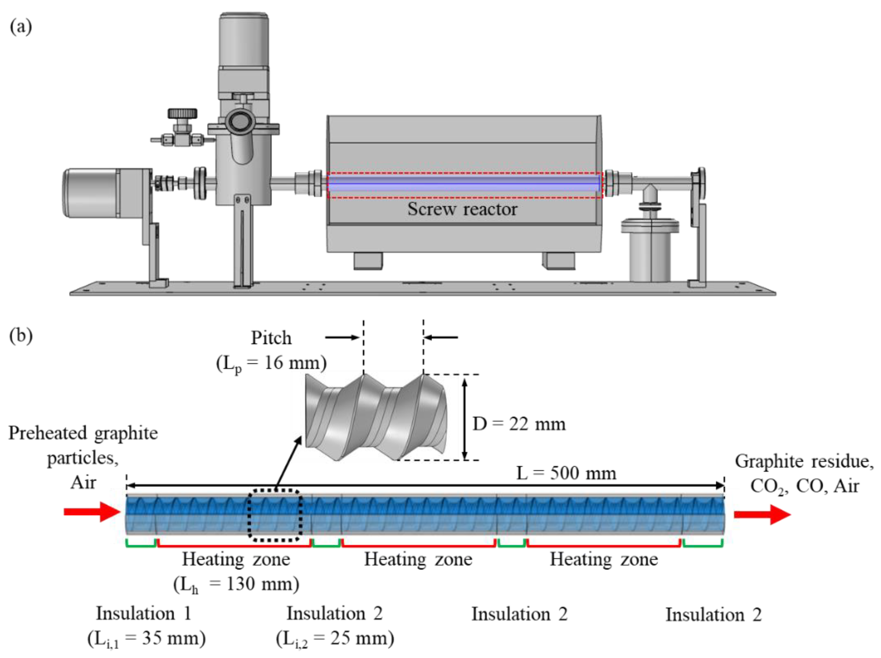
2.2.1. Dimensions of the Experimental Screw Reactor

When graphite particles in a screw reactor are transported from the inlet to the outlet by rotating the screw of the reactor, the heat induced by particles rubbing against the reactor wall increases the temperature of the graphite and initiates thermal gasification under an oxidizing atmosphere. In numerical simulations of this graphite flowing through the screw reactor, a single-phase Eulerian model was used to track the graphite particles and the progress of their conversion to carbon–oxygen compound gases through the reactor. Figure 1a,b shows a schematic diagram of the screw reactor system and dimensions of the computational domain used in this study. The screw reactor has three heating zones separated by insulators and a single revolving screw that thermally gasifies graphite particles dried at 373 K. The reactor length L, the reactor tube diameter D, and the screw thread pitch Lp, are 0.5, 0.022, and 0.016 m, respectively. After solving the momentum and continuity equations, the heat and mass transfer equations are coupled in the numerical calculation for the three dimensions of the computational domain to predict numerically the spatial evolution of graphite gasification along the axial direction of the screw reactor.

2.2.2. Boundary Conditions

A sliding and no flux condition was introduced to the screw reactor shell to conduct numerical computations for graphite flow. At the reactor inlet, atmospheric pressure and a constant concentration were used, while at the exit, atmospheric pressure and an outflow condition were used. The moving mesh method, in conjunction with these applied conditions, was used to make graphite particles flow continuously in the computational domain relying only on the screw’s rotation. The influence of particle size distribution on the hydrodynamics, heat transfer, and mass transfer of graphite flow in the screw reactor domain was disregarded in the numerical simulations since the graphite particles were assumed to have a constant diameter. However, the thermal conductivity and heat capacity of the graphite flow were considered to depend on the temperature [38]. The screw reactor’s three-dimensional computational domain was built using tetrahedral elements ranging in size from 0.16 to 1.2 mm. The total number of mesh elements was estimated to be around 2.3 × 10⁷. The predicted average velocity at the outlet of the reactor obtained using this mesh grid was compared with the results obtained from various mesh grids to confirm the independence of the grid size. A workstation with two 20-core processors (2.1 GHz, Xeon) and 1 TB of RAM was used to perform the computations. Depending on the screw rotational speed and the temperature of the reactor shell, the real computing time for each simulation ranged from 6 to 14 h.

3. Results and Discussion

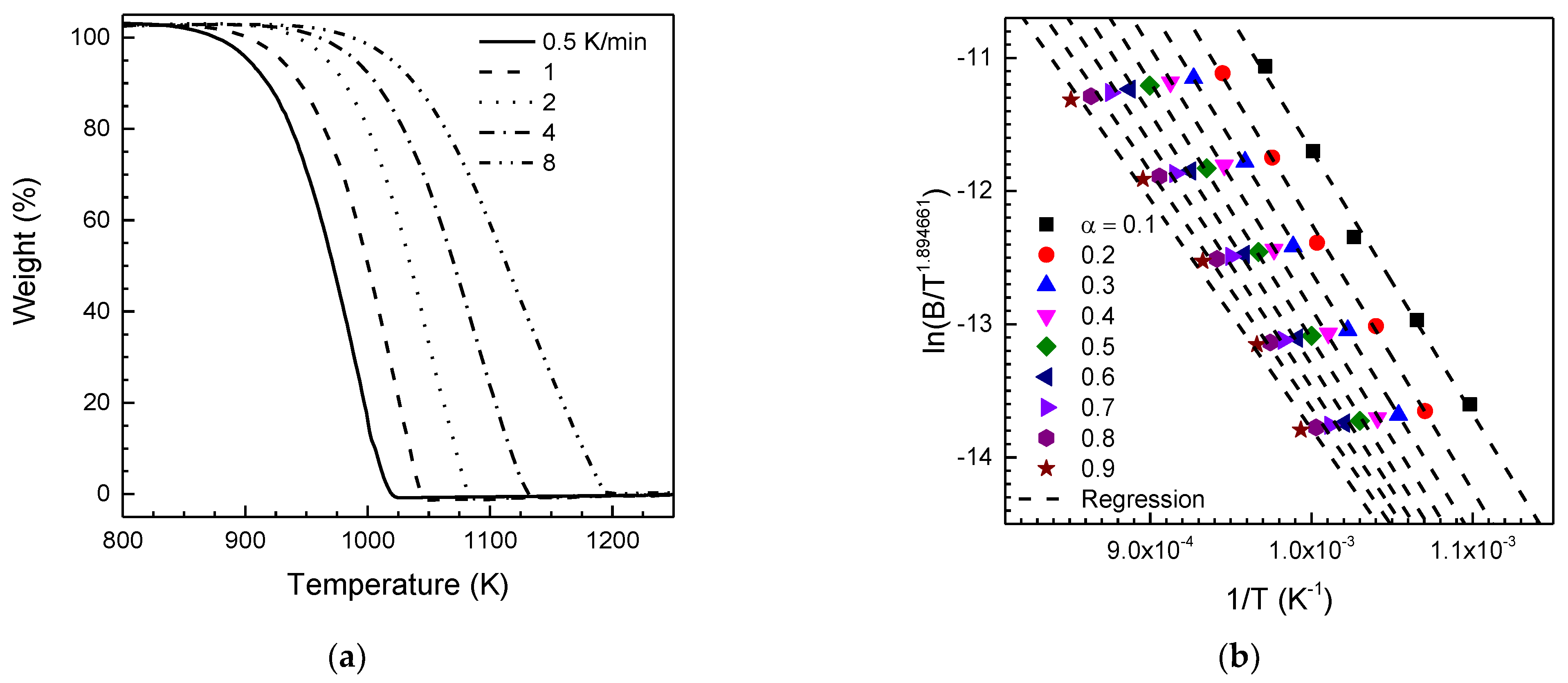
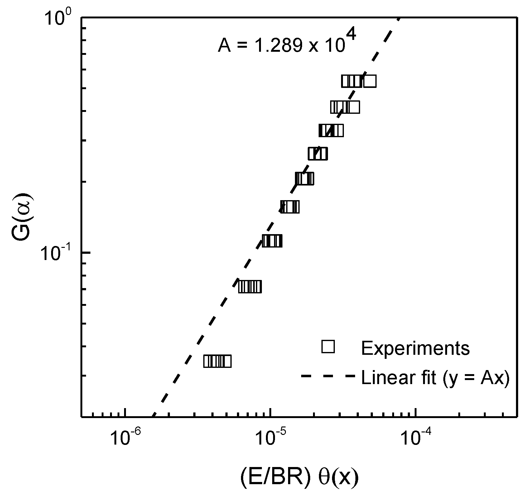
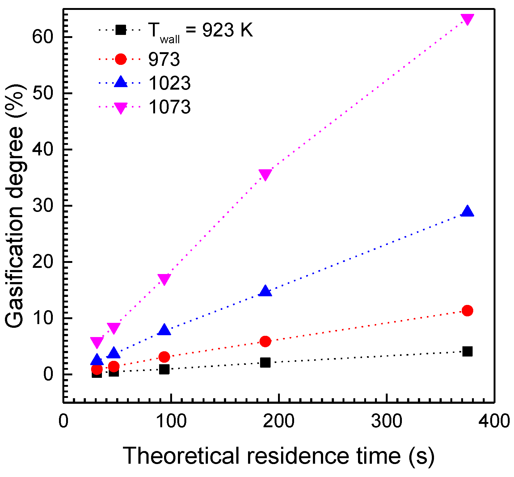
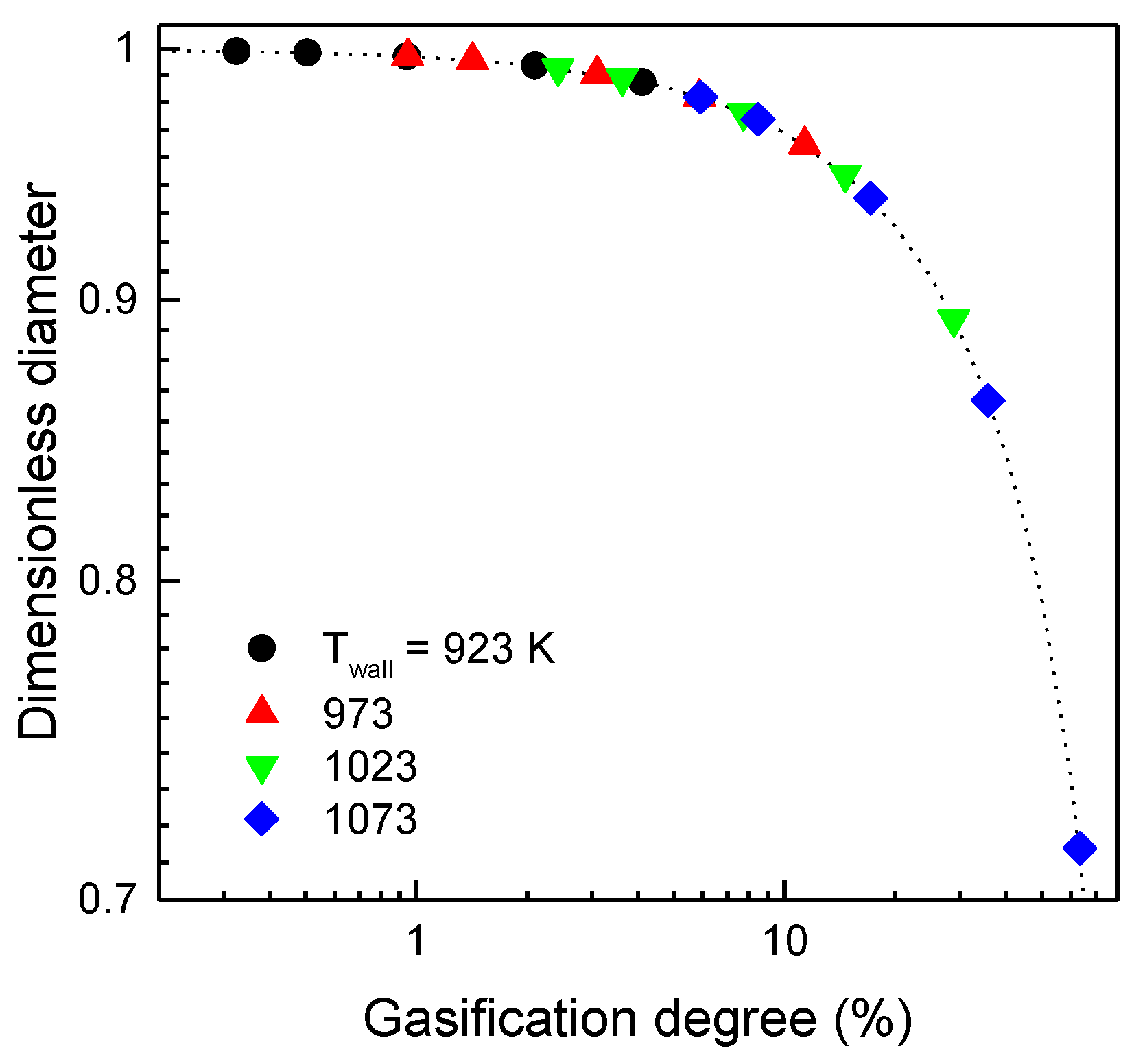
3.1. Kinetic Model for Graphite Gasification

The dynamic weight loss data acquired from the nonisothermal TG tests on high-purity graphite powder (Alfa Aesar, 99.9995%, 325 mesh) was applied to develop the kinetic model and parameters for gasification of the pretreated radioactive graphite waste. In the nonisothermal TG experiment, a graphite powder sample in the TGA (TA Instruments, New Castle, DE, USA) was heated from ambient temperature to 1273 K at a constant rate (0.5, 1, 2, 4, and 8 K/min). For the thermal gasification of graphite powder with an oxidizing agent, the TG furnace was maintained by purging dry air (N2 and O2) at a constant rate of 50 mL/min during experiments.
Figure 2a,b shows the dynamic weight loss results of the graphite powder obtained from the nonisothermal TG experiments, and their isoconversion plot, respectively. Comparing the dynamic weight loss curves in Figure 2a, the shape of all curves is similar, but the curves shift toward higher temperature as the heating rate increases. These results mean that the thermal gasification reaction of graphite powder at different heating rates can be treated as a single kinetic mechanism. Therefore, it is expected that the activation energy of the graphite powder and a pre-exponential factor have constant values at all heating rates. As previously mentioned, the activation energy of graphite gasification, one of the kinetic parameters, can be determined using Equation (15). Figure 2b shows the linear regression lines for scatter plots of B/T1.894661 versus dT−1 for each conversion degree. These regression lines, constructed to evaluate the slopes d ln(B/T1.894661)/dT−1, were used to calculate the activation energy of the graphite powder for each level of conversion by inserting their slopes into Equation (15). Comparing the slope of the regression line in Figure 2b, depending on the conversion level, the calculated apparent activation energy is slightly different. However, the apparent activation energy changed insignificantly with regard to the conversion level. Therefore, the activation energy remains the same during nonisothermal thermogravimetric experiments, as we expect. The activation energy of the graphite powder was determined to be 153.9 ± 10.7 kJ/mol. This number shows good agreement with the reported activation energy of KRR-2 nuclear graphite, 166.6 kJ/mol [39].
The kinetic function for gasification of graphite powder can be calculated by comparing the experimental master curve to the theoretical master curve after determining the activation energy. Applying the determined value of the activation energy into Equation (12), the experimental master plot θ ( x ) / θ ( x 0.5 ) for gasification of graphite powder was constructed. In Figure 3, the experimental master plot obtained is compared with the theoretical master curves G ( x ) / G ( x 0.5 ) plotted using the kinetic model functions listed in Table 1. None of the listed kinetic functions match all values on the experimental master curve. However, among the kinetic model functions in the list, the theoretical master curve constructed using the kinetic model R2 appeared graphically to be the most suitable plot for representing the thermal gasification of the graphite powder. As shown in the figure, this result was also proved by comparing the standard deviation mean values SD to evaluate the average distribution of the theoretical values relative to the experimental master curve.
Because the activation energy and kinetic model function were determined, the pre-exponential factor is the last kinetic parameter needed to establish the Arrhenius equation for gasification of the graphite powder. The pre-exponential parameter was determined using Equation (11). Actually, the activation energy affected by the oxygen partial pressure in ambient air can affect the determination of the pre-exponential parameter for gasification of the graphite powder. However, the dry gas flowing around the TG furnace during nonisothermal thermogravimetric experiments can reduce the changes in the oxygen partial pressure, and the activation energy could be consistent. As with the activation energy, the pre-exponential parameter also has a constant value during the thermal gasification reaction. Therefore, a straight line passing through the origin should be plotted as G ( α ) versus ( E / R T ) θ ( x ) , and its slope is equal to the pre-exponential parameter’s value. As shown in Figure 4, the value of the slope of the linear line fitted to the experimentally obtained G ( α ) for gasification of the graphite powder is 12,892.36 s−1. Because all the kinetic parameters for describing the gasification of the graphite powder are determined by analyzing the results of nonisothermal TG experiments, the governing equation for the mass transfer of graphite can be replaced by the established Arrhenius equation. The final form of Equation (4) is represented in terms of the graphite concentration:
c t + u c = A exp ( E R T ) c 0 1 / 2 c 1 / 2
where c 0 is the feed concentration at the inlet of the screw reactor.

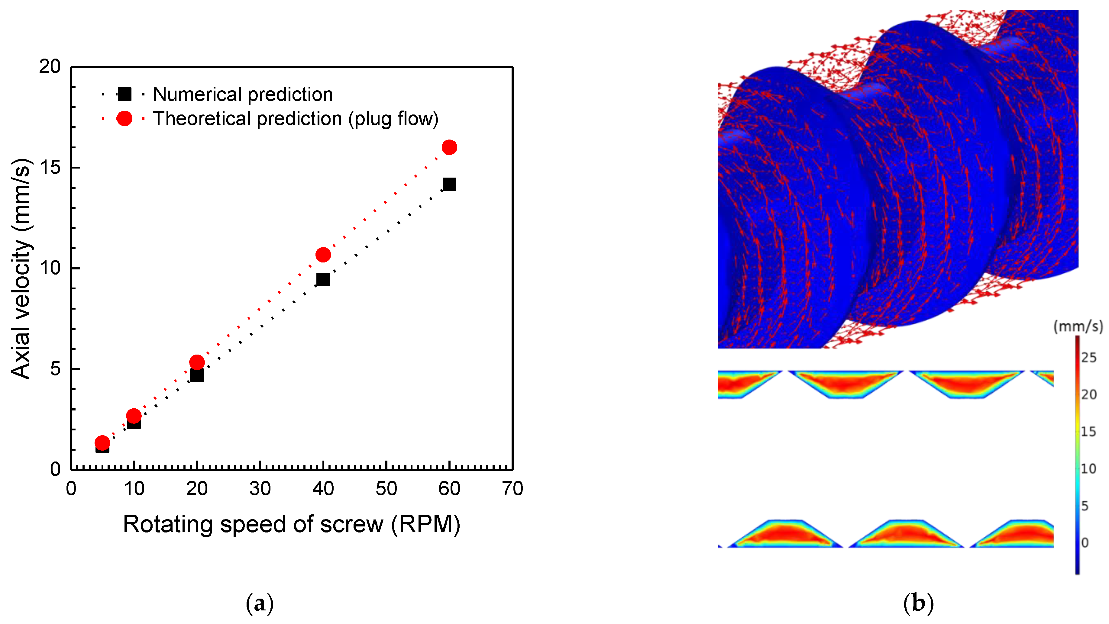
3.2. Hydrodynamics of Graphite Flow

To characterize the graphite flow in the laboratory-scale screw reactor, the average axial velocities of the nonthermal gasification graphite flow at different screw rotating speeds were compared to that of an ideal plug flow shown in Figure 5a. If thermal gasification of the graphite flow does not occur through the screw reactor, the axial movement of graphite particles only depends on the rotating velocity of the screw. Given that the rotating screw drives graphite particle flow in the axial direction toward the reactor outlet, the axial velocity of the graphite particle flow is theoretically similar to ideal plug flow, and its value equals that provided by dividing the screw pitch length by the rotation period of the screw. The comparison results in the figure show that the axial velocities obtained from the conducted numerical calculations are about 10% lower than the theoretical velocity obtained using plug flow analysis. This result agrees with the numerical and experimental results reported by Shi et al. [30] and Waje et al. [40]. The graphite particles flow in the screw reactor exhibit not only axial flow but also rotational flow. However, the average velocity calculated theoretically using plug flow analysis does not account for the swirling flow of graphite particles along the rotating screw. Figure 5b shows the velocity vectors and the axial velocity field of the screw reactor at the rotating screw of 60 rpm. As shown in the figure, the frictional interaction between the particles and the rotating screw surface drives the particles to move along the rotating surface of the screw as the velocity vectors indicate. However, there are also rotating velocity vectors in the opposite direction at the surface of the tube wall, due to the relative motion of the tube wall to the rotating screw. These counter-rotating flows of particles in each pitch of the screw cause particles to mix spatially and reduce the axial velocity of the particle flow while the rotating screw conveys bulk particles to the outlet of the reactor.

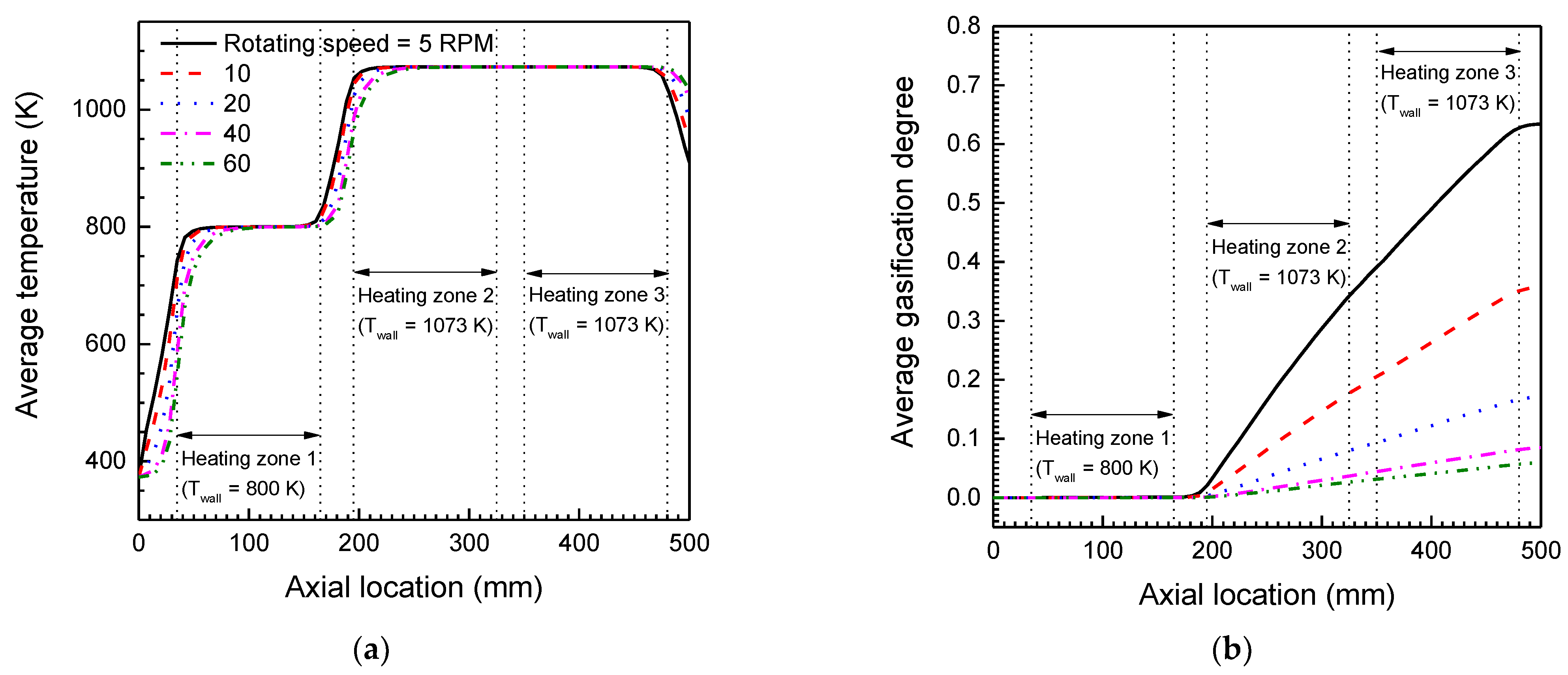
3.3. Operating Parameters for the Screw Reactor

The temperature of the screw reactor wall and the rotational speed of the screw, which affects the reaction rate of thermal gasification, determine the gasification degree of particles flowing from the reactor outlet. Therefore, the screw reactor can decontaminate the pretreated radioactive graphite waste by controlling the gasification degree of the particle surfaces where most of the radiocarbons are located. In this numerical simulation, the temperature of the reactor and the rotating velocity of the screw are changed one at a time to determine how they affect the gasification of graphite particles in ambient air. The value for the rotating velocity of the screw was changed from 5 to 60 rpm, and the surface temperature of both heating zone 2 and 3 of the reactor tube were varied from 923 to 1073 K to gasify the graphite. In the numerical simulations conducted, the temperature of heating zone 1 of the reactor tube was maintained at 800 K as a preheating region to provide a constant gasification rate for the graphite flowing through the reactor by minimizing the effect of the thermal boundary layer developing at the inlet region of the screw reactor.
Figure 6a,b represents variations in the average cross-sectional temperature and the degree of gasification of graphite flow in the reactor in the axial direction. The average temperature of the graphite in each heating region reached the reactor wall temperature. The dried graphite particles, passing through the preheating region (heating zone 1) of the reactor at less than their gasification temperature, start to gasify from the secondary heating region of the reactor. Even though the graphite flow is preheated to 800 K before entering the higher temperature region of the reactor for the gasification reaction, thermal development of the graphite flow at the higher temperature region is still observed in Figure 6a, and this thermally developing region also expands as the rotating velocity of the screw increases. However, the changes in the axial length of the highest temperature region were negligible because decreases of the thermally developing region near the outlet of the reactor compensated for expansion of the thermal developing length in the secondary heating region of the reactor. The average gasification degree of the graphite particles changes along the axial direction of the reactor, as shown in Figure 6b. Depending on the reactor temperature, the graphite particles passing through the first heating region of the reactor started to gasify into the carbon–oxygen compound gas. In the maximum temperature zone (heating zone 2 and 3), the gasification degrees, which were obtained by averaging the gasification progress of graphite particles in an axial cross-sectional area of the reactor, began to increase at a constant rate. However, due to the influence of the thermal development of the graphite particle flow, the axial position of the gasification area migrated slightly toward the exit when the screw rotational velocity was increased.
Depending on the radioactive carbon distribution at the pretreated graphite particles, the screw reactor’s operating conditions are determined to decontaminate the radioactive graphite waste properly by controlling the gasification degree of the graphite particles. Figure 7 shows the numerically calculated gasification degrees of graphite particles flowing out of the screw reactor against their theoretical residence time, as determined using plug flow analysis. The average reaction progress at the reactor’s outflow rises linearly with increasing residence time as evaluated by the screw’s rotational velocity. The reaction rate at the same residence time increases as the screw reactor’s wall temperature rises. For all graphite particles flowing out of the screw reactor, when the temperature of the high temperature region of the reactor is less than 1023 K, the screw reactor can only gasify less than 12% of the input graphite particles. However, as the temperature rises to 1073 K, the screw reactor can gasify about 64% of the feed graphite at the residence time of 375 s, which corresponds approximately to the screw’s theoretical rotational velocity 5 rpm. Moreover, at a temperature of 1073 K, the rotational velocity of the screw at which more than 12% of the feed graphite is gasified, increases to about 66 rpm, corresponding to the theoretical residence time of 67 s.
When the granular graphite, which is composed of rigid spheres with a constant diameter of 0.005 m, passes through the screw reactor, the diameter of the spherical particles is reduced by gasification of their surface with ambient air. The predicted gasification degree may be used to estimate the particle diameter flowing out of the reactor. The calculated dimensionless diameters, which represent the diameter ratio of the product particles to the feed particles, are shown in Figure 8. In the figure, as the temperature increases or the rotational velocity decreases, the dimensionless diameter of the graphite particles decreases. By raising the rotational velocity of the screw from 5 to 60 rpm at the maximum temperature of the reactor shell (1073 K), the diameter of the feed graphite particle is decreased from 28 to 2%. This result strongly supports the notion that controlling the gasification degree by the operating parameters of the screw reactor can decontaminate the pretreated radioactive graphite waste by gasifying the radioactive carbon mainly distributed on the surface of the graphite, together with a limited amount of graphite matrix.

4. Conclusions

In this study, a laboratory-scale screw reactor for decontaminating pretreated radioactive graphite waste was numerically investigated to characterize the hydrodynamics and thermal gasification of granular graphite flow in the screw reactor. To simulate efficiently the three-dimensional graphite flow in the screw reactor, a simple viscoelastic continuum model, in conjunction with the gasification kinetic model established from nonisothermal TG experiments, was used as a comprehensive numerical model for granular flow in the screw reactor.
The numerical results on the hydrodynamics of granular flow concerning the axial average velocity of the graphite flow inside the reactor were compared with the theoretical values obtained using plug flow analysis. The simulation results show that counter-rotating flow generated along the rotating screw by the relative motion of the tube wall to the rotating screw causes particles to mix spatially and reduces their axial velocity. As a result, the axial velocity predicted by the numerical calculations is lower than the value obtained using plug flow analysis at the same rotational velocity of the reactor’s screw.
A single-step kinetic model with an activation energy of 153.9 kJ/mol and a frequency factor of 12,892.36 s−1, determined from the experiments of nonisothermal TGA of nuclear–grade graphite powder, was used to simulate the gasification of graphite with ambient air in the reactor. Applying this well-developed gasification kinetic model to the numerical simulation, the gasification progress of graphite particles along the axial direction was predicted. The thermal gasification degree of the graphite particles flowing out of the reactor is determined by the screw rotational velocity and the reactor shell temperature, according to the simulation results. A higher rotational speed of the screw results in a larger dimensionless diameter of the graphite particles at the outlet owing to the shorter residence time. However, the dimensionless diameter of the graphite particles decreases as the wall temperature of the reactor increases at the same rotational speed of the screw. This is due to the temperature dependence of the gasification rate. Therefore, the screw reactor, which can manipulate the residence time and the temperature of graphite particles, can achieve the homogeneous size reduction of the graphite particles by the controlled gasification reaction progress. It means that the pretreated radioactive graphite waste can be decontaminated by gasification of the particle surface where most 14C is located. By using these numerical predictions, the optimized operation conditions of the screw reactor for the radioactive graphite waste treatment process can be determined for decontaminating pretreated radioactive graphite waste by gasifying the surface of the pretreated graphite waste.

Funding

This work was supported by a National Research Foundation of Korea (NRF) grant funded by the Korea government (MSIT) (NRF-2021R1/1A2058143).

Institutional Review Board Statement

Not applicable.

Informed Consent Statement

Not applicable.

Data Availability Statement

All data presented in this study are available from the corresponding author upon reasonable request.

Acknowledgments

The author thanks H.C. Yang of the Korea Atomic Energy Research Institute in Daejeon, Republic of Korea, for valuable discussions on nonisothermal TGA and radioactive graphite waste management.

Conflicts of Interest

The author declares no conflict of interest.

Nomenclature

A Pre-exponential factor
B Constant heating rate
c Particle concentration
C p Specific heat capacity
d Diameter
D Reactor tube diameter
E Activation energy
I Dimensionless inertial number
I o Dimensionless material parameter
g Gravitational acceleration
k Heat conductivity
L Reactor length
L h Heating zone length
L p Screw thread pitch
P Pressure
P Normal confinement pressure
R Gas constant
T Temperature
u Flow velocity vector
t Time
Greek
α Fractional conversion
γ ˙ Shear rate
δ i j Kronecker delta
η e f f Effective viscosity
μ Friction parameter
μ s Static friction coefficient
μ d Dynamic friction coefficient
ρ Bulk density
σ i j Stress tensor
τ i j Shear stress tensor
Subscript
p Particle
i Insulation
0 Feed

References

  1. IAEA. Characterization, Treatment and Conditioning of Radioactive Graphite from Decommissioning of Nuclear Reactors; International Atomic Energy Agency: Vienna, AU, USA, 2006. [Google Scholar]
  2. Wareing, A.; Abrahamsen-Mills, L.; Fowler, L.; Grave, M.; Jarvis, R.; Metcalfe, M.; Norris, S.; Banford, A.W. Development of integrated waste management options for irradiated graphite. Nucl. Eng. Technol. 2017, 49, 1010–1018. [Google Scholar] [CrossRef]
  3. Fuks, L.; Herdzik-Koniecko, I.; Kiegiel, K.; Zakrzewska-Koltuniewicz, G. Management of radioactive waste containing graphite: Overview of methods. Energies 2020, 13, 4638. [Google Scholar] [CrossRef]
  4. Wickham, A.; Steinmetz, H.-J.; O’Sullivan, P.; Ojovan, M.I. Updating irradiated graphite disposal: Project ‘GRAPA’ and the international decommissioning network. J. Environ. Radioact. 2017, 171, 34–40. [Google Scholar] [CrossRef] [PubMed]
  5. Fu, K.; Chen, M.; Wei, S.; Zhong, X. A comprehensive review on decontamination of irradiated graphite waste. J. Nucl. Mater. 2022, 559, 153475. [Google Scholar] [CrossRef]
  6. Perler, I.C.S.; Beer, H.-F.; Muth, J.; Kramer, A. Dismantling of the DIORIT research reactor—Conditioning of activated graphite. J. Environ. Radioact. 2019, 196, 199–203. [Google Scholar] [CrossRef]
  7. Raty, A.; Lavonen, T.; Leskinen, A.; Likonen, J.; Postolache, C.; Fugaru, V.; Bubueanu, G.; Lungu, C.; Bucsa, A. Characterization measurements of fluental and graphite in FiR1 TRIGA research reactor decommissioning waste. Nucl. Eng. Des. 2019, 353, 110198. [Google Scholar] [CrossRef]
  8. Remeikis, V.; Plukiene, R.; Plukis, A.; Barkauskas, V.; Gudelis, A.; Druteikiene, R.; Govzdaite, R.; Juodis, L.; Duskesas, G.; Lagzdina, E.; et al. Characterisation of RBMK-1500 graphite: A method to identify the neutron activation and surface contamination terms. Nucl. Eng. Des. 2020, 361, 110501. [Google Scholar] [CrossRef]
  9. Payne, L.; Heard, P.J.; Scott, T.B. Examination of surface deposits on oldbury reactor core graphite to determine the concentration and distribution of 14C. PLoS ONE 2016, 11, e0164159. [Google Scholar] [CrossRef] [Green Version]
  10. Tzelepi, A.; Metcalfe, M.P.; Dinsdale-Potter, J.H.; Wilkinson, S.; Copeland, G. Radiological characterisation of graphite components in advance gas-cooled reactor cores. J. Environ. Radioact. 2020, 220–221, 106296. [Google Scholar] [CrossRef]
  11. Ambrosi, A.; Chua, C.K.; Khezri, B.; Sofer, Z.; Webster, R.D.; Pumera, M. Chemically reduced graphene contains inherent metallic impurities present in parent natural and synthetic graphite. Proc. Natl. Acad. Sci. USA 2012, 32, 12899–12904. [Google Scholar] [CrossRef] [Green Version]
  12. Wareing, A.; Abrahamsen, L.; Banford, A.; Metcalfe, M.; Lensa, W.V. CARBOWASTE: Treatment and Disposal of Irradiated Graphite and Other Carbonaceous Waste; EURATOM-FZJ: Jülich, Germany, 2013. [Google Scholar]
  13. Nightingale, R.E. Nuclear Graphite; Academic Press: New York, NY, USA, 1962. [Google Scholar]
  14. Vulpius, D.; Baginski, K.; Kraus, B.; Thomauske, B. Thermal treatment of neutron-irradiated nuclear graphite. Nucl. Eng. Des. 2013, 265, 294–309. [Google Scholar] [CrossRef]
  15. Metcalfe, M.P.; Tzelepi, A.; Copeland, G. The release of carbon-14 from irradiated PGA graphite by thermal treatment in air. Ann. Nucl. Energy 2019, 133, 110–121. [Google Scholar] [CrossRef]
  16. Theodosiou, A.; Jones, A.N.; Marsden, B.J. Thermal oxidation of nuclear graphite: A large scale waste treatment option. PLoS ONE 2017, 12, e0182860. [Google Scholar] [CrossRef] [PubMed] [Green Version]
  17. LaBrier, D.; Dunzik-Gougar, M.L. Identification and location of 14C-bearing species in thermally treated neutron irradiated graphites NBG-18 and NBG-25: Pre- and post-thermal treatment. J. Nucl. Mater. 2015, 460, 174–183. [Google Scholar] [CrossRef]
  18. Dunzik-Gougar, M.L.; Smith, T.E. Removal of carbon-14 from irradiated graphite. J. Nucl. Mater. 2014, 451, 328–335. [Google Scholar] [CrossRef]
  19. Smith, T.E.; Mccrory, S.; Dunzik-Gougar, L.M. Limited oxidation of irradiated graphite waste to remove surface carbon-14. Ncul. Eng. Technol. 2013, 45, 211–218. [Google Scholar] [CrossRef] [Green Version]
  20. Theodosiou, A.; Jones, A.N.; Burton, D.; Powell, M.; Rogers, M.; Livesey, V.B. The complete oxidation of nuclear graphite waste via thermal treatment: An alternative to geological disposal. J. Nucl. Mater. 2018, 507, 208–2017. [Google Scholar] [CrossRef]
  21. Pageot, J.; Rouzaud, J.-N.; Gosmain, L.; Duhart-Barone, A.; Comte, J.; Deldicque, D. 14C selective extraction from French graphite nuclear waste by CO2 gasification. Prog. Nucl. 2018, 105, 279–286. [Google Scholar] [CrossRef]
  22. Pageot, J.; Rouzaud, J.-N.; Ahmad, M.A.; Deldicque, D.; Gadiou, R.; Dentzer, J.; Gosmain, L. Milled graphite as a pertinent analogue of French UNGG reactor graphite waste for a CO2 gasification based treatment. Carbon 2015, 86, 174–187. [Google Scholar] [CrossRef]
  23. Lo, I.-H.; Yeh, T.-K.; Patterson, E.A.; Tzelepi, A. Comparison of oxidation behaviour of nuclear graphite grades at very high temperatures. J. Nucl. Mater. 2020, 532, 152054. [Google Scholar] [CrossRef]
  24. Worth, R.N.; Theodosiou, A.; Bodel, W.; Arregui-Mena, J.D.; Wickham, A.J.; Jones, A.N.; Mummery, P.M. The distribution and selective decontamination of carbon-14 from nuclear graphite. J. Nucl. Mater. 2021, 556, 153167. [Google Scholar] [CrossRef]
  25. Zhou, Y.; Dong, Y.; Yin, H.; Li, Z.; Yan, R.; Li, D.; Gu, Z.; Sun, X.; Shi, L.; Zhang, Z. Characterizing thermal-oxidation behaviors of nuclear graphite by combining O2 supply and micro surface area of graphite. Sci. Rep. 2018, 8, 13400. [Google Scholar] [CrossRef] [PubMed]
  26. Qi, F.; Wright, M.M. Particle scale modeling of heat transfer in granular flow in a double screw reactor. Powder Technol. 2018, 335, 18–34. [Google Scholar] [CrossRef]
  27. Qi, F.; Wright, M.M. A DEM modeling of biomass fast pyrolysis in a double auger reactor. Int. J. Heat Mass Transf. 2020, 150, 119308. [Google Scholar]
  28. Choi, Y.J.; Yang, I.-H. Numerical investigation of thermal gasification in enclosed screw-conveyor reactor for removal of 14C from irradiated graphite waste. J. Nucl. Sci. Technol. 2020, 57, 839–851. [Google Scholar] [CrossRef]
  29. Tang, H.; Zong, Y.; Zhao, L. Numerical simulation of micromixing effect on the reactive flow in a co-rotating twin screw extruder. Chin. J. Chem. Eng. 2016, 24, 1135–1146. [Google Scholar] [CrossRef]
  30. Shi, X.; Ronsse, F.; Roegiers, J.; Pieters, J.G. 3D eulerian-eulerian modeling of a screw reactor for biomass thermochemical conversion. Part 1: Solids flow dyanmics and backmixing. Renew. Energy 2019, 143, 1465–1476. [Google Scholar] [CrossRef]
  31. Shi, X.; Ronsse, F.; Nachenius, R.; Pieters, J.G. 3D eulerian-eulerian modeling of a screw reactor for biomass thermochemical conversion. Part 2: Slow pyrolysis for char production. Renew. Energy 2019, 143, 1477–1487. [Google Scholar] [CrossRef]
  32. Jalalifar, S.; Abbassi, R.; Garaniya, V.; Salehi, F.; Papari, S.; Hawboldt, K.; Strezov, V. CFD analysis of fast pyrolysis process in a pilot-scale auger reactor. Fuel 2020, 273, 117782. [Google Scholar] [CrossRef]
  33. COMSOL AB. Comsol Multiphysics 5.4 User’s Guide; COMSOL Inc.: Burlington, VT, USA, 2018. [Google Scholar]
  34. Franci, A.; Cremonesi, M. 3D regularized μ(I)-rheology for granular flows simulation. J. Comput. Phys. 2019, 378, 257–277. [Google Scholar] [CrossRef]
  35. Forterre, Y.; Pouliquen, O. Granular flows. In Glasses and Grains: Poincare Seminar 2009; Duplantier, B., Halsey, T.C., Rivasseau, V., Eds.; Birkhauser: Basel, CH, USA, 2011; pp. 77–104. [Google Scholar]
  36. Tang, W.; Liu, Y.; Zhang, H.; Wang, C. New approximate formula for Arrhenius temperature integral. Thermochim. Acta. 2003, 408, 39–43. [Google Scholar] [CrossRef]
  37. Tang, W.; Chen, D.; Wang, C. Kinetic study on the thermal dehydration of CaCO3·H2O by the master plots method. AIChE J. 2006, 52, 2211–2216. [Google Scholar]
  38. IAEA. Thermophysical Properties of Materials for Nuclear Engineering: A Tutorial and Collection of Data; International Atomic Energy Agency: Vienna, AU, USA, 2008. [Google Scholar]
  39. Yang, H.-C.; Eun, H.-C.; Lee, D.-G.; Jung, C.-H.; Lee, K.-W. Analysis of combustion kinetics of powdered nuclear graphite by using a non-isothermal thermogravimetric method. J. Nucl. Sci. Technol. 2006, 42, 869–876. [Google Scholar] [CrossRef]
  40. Waje, S.S.; Patel, A.K.; Thorat, B.N.; Mujumdar, A.S. Study of residence time distribution in a pilot-scale screw conveyor dryer. Dry. Technol. 2007, 25, 249–259. [Google Scholar] [CrossRef]
Figure 1. (a) Schematic diagram of the screw reactor system. (b) Dimensions of the screw reactor for the computational domain.
Processes 10 00398 g001
Figure 2. (a) Dynamic mass loss of nuclear-grade graphite powder at various heating rates under dry air. (b) Isoconversional plot for calculating the activation energy of nuclear-grade graphite gasification under dry air.
Processes 10 00398 g002
Figure 3. Determination of gasification kinetic model function by comparison of a theoretical master curve to the experimental results.
Processes 10 00398 g003
Figure 4. Determination of pre-exponential parameter A by linear fit to the experimental data.
Processes 10 00398 g004
Figure 5. (a) Comparison of the average axial velocities of granular graphite flow predicted by numerical simulation and the plug flow analysis. (b) Velocity vectors and axial velocity field of graphite flow in the pitch of the screw generated by the rotating screw speed of 60 rpm.
Processes 10 00398 g005
Figure 6. Predicted average cross-sectional temperature (a) and gasification degree (b) curves of graphite flow along the axial direction for various rotating velocities of the screw.
Processes 10 00398 g006
Figure 7. Average cross-sectional gasification degrees of graphite particle flow at the screw reactor outlet.
Processes 10 00398 g007
Figure 8. Dimensionless diameter decrease of the feed graphite particles flowing from the screw reactor.
Processes 10 00398 g008
Table 1. Common kinetic model functions f ( α ) and G ( α ) used to examine gasification of graphite powder in this work.
SymbolKinetic Models [28]f(α)G(α)
A1Avarmi–Erofeev (n = 1)2(1 − α)[−ln(1 − α)]1/2[−ln(1 − α)]1/2
A3Avarmi–Erofeev (n = 3)3(1 − α)[−ln(1 − α)]2/3[−ln(1 − α)]1/3
R2Phase boundary-controlled reaction (contracting area)2(1 − α)1/21 − (1 − α)1/2
R3Phase boundary-controlled reaction (contracting volume)3(1 − α)2/31 − (1 − α)1/3
D1Diffusion (1D)(1/2)αα2
D3Diffusion (3D, Jander equation)3(1 − α)1/3/2[(1 − α)−1/3 − 1][1 − (1 − α)1/3]2
P1Power law4α3/4α1/4
P2Power law3α2/3α1/3
F1Chemical reaction (first-order)1 − α−ln(1 − α)
Publisher’s Note: MDPI stays neutral with regard to jurisdictional claims in published maps and institutional affiliations.

