Article

Mechanics Principle and Implementation Technology of Surrounding Rock Pressure Release in Gob-Side Entry Retaining by Roof Cutting

1
School of Civil Engineering, Qingdao University of Technology, Qingdao 266520, China
2
State Key Laboratory for Geomechanics and Deep Underground Engineering, Beijing 100083, China
3
Shaanxi Ruineng Coal Co., Ltd., Yan’an 727307, China
*
Author to whom correspondence should be addressed.
Processes 2022, 10(12), 2629; https://doi.org/10.3390/pr10122629
Submission received: 4 October 2022 / Revised: 27 November 2022 / Accepted: 5 December 2022 / Published: 7 December 2022

Abstract

:
Improving coal resource mining rates has long been a focus of coal industry research. The gob-side entry retaining by roof cutting (GERRC) is a new coal mining technology that has gained popularity in China due to its high mining rate and safety. Based on the GERRC technology, the precise technical procedure is elaborated, and the fundamental idea of pressure relief is explored through creating a structural mechanics model of the surrounding rock in this paper. The results of mechanical analysis show that the primary mechanism of roof pressure release is to weaken the integrity of the roof, thereby reducing the ultimate bending moment of the rock stratum. In addition, an additional strategy for pressure release is suggested in this research, involving the weakening of the roof rock by the creation of dense pressure-released holes. The results of the engineering field experimentation demonstrate that the dense pressure-released holes can completely replace the conventional blasting technology of the past to achieve the effect of releasing the roof pressure, thus avoiding the use of hazardous and challenging-to-obtain explosives and demonstrating safety, reliability, and feasibility.

1. Introduction

Coal is a well-known non-renewable source of solid energy. The remaining resources will eventually dwindle as a result of the predatory exploitation of coal resources, and coal will increase in value. China’s coal output and consumption are undoubtedly the highest in the world due to the necessity of China’s economic building and social development [1]. With the traditional method of mining coal, a significant portion of the coal resources are left permanently below the surface and unable to be mined since at least one protective coal pillar must be reserved and two gates must be dug beforehand. Additionally, many mining costs arise as a result of these massive amounts of tunnel excavation [2]. Additionally, this coal mining technology makes it simple to create maintenance challenges for roadways due to the stress concentration of coal pillars and the fact that it is easy to create safety issues due to an excessive gas buildup in the working face [3,4]. The advancement of new coal mining technology is a hot topic that scholars all over the world are watching closely.
A mining technique with a high rate of coal recovery was introduced in the 20th century and gained popularity in China starting in the 1950s. This technique is known as “gob-side entrance retaining by filling (GERF)” [5,6]. This method is particularly well-liked in China because it makes it impossible to establish the special protective coal pillar and allows for a more than 50% reduction in the quantity of road excavation. This technology has undergone extensive investigation in recent decades from scientists and engineers around the globe, which has accelerated its development [7,8]. For a long time, the filling materials and support technology on the side of the gob have been the research focus of engineers and scholars, because it is also one of the most important problems that must be solved in engineering practice [9,10,11]. Over the years, countless innovative filling materials, including concrete, cementitious compounds, and materials with a high water content, have been created and are utilized often in engineering [12,13,14,15,16]. Gob-side entry support commonly uses concrete-filled steel tubular columns, combined hydraulic supports, high-strength anchor bolts, and their combined support forms [17,18,19]. Many scholars have conducted extensive research on the structural traits, deformation traits, and control technologies of the surrounding rock under this technology, and the findings are highly impressive [20,21,22]. The promotion and use of GERF is greatly impacted by some researchers’ analysis of a large number of typical engineering scenarios and systematic summary of the application circumstances of gob side filling materials and support technology [23].
However, the GERF must be supplied with a complicated filling mechanism and the designed artificial filling body is easily generates excessive stress concentration, which raises the mining cost and poses potential safety risks. In light of this, a new alternative called the GERRC was put up by Professor Manchao He at the beginning of this century [24,25]. The GERRC uses the roof cutting to change the traditional roadway surrounding rock structure and cut off part of the roof in the mining area [24]. The main goal of this method is to reduce the strength of the physical link between the roof rock and the road in a specific way, hence reducing or preventing the transmission of stress between them and reducing or even eliminating some of the surrounding rock pressure. The roof cutting down in the gob then collapses, forming gangue, which fills the gob. The use of the overlying main roof structure of the roadway’s gangue self-bearing characteristics play a supporting role, thereby maintaining the stability of the roadway’s surrounding rock structure [26]. To ensure the stability of the gob-side entry, it is undoubtedly also important to work in conjunction with the support of high prestressed anchor cable and temporary vertical supporting structure. After the surrounding rock movement is completed, the roof depends on the gangue in the goaf and the coal body on the other side to keep it from collapsing. This technique has been used in numerous coal mines after more than 10 years of development, and numerous scholars or engineering professionals have completed numerous studies on it. The roof cutting as a major pressure relief means for the roadway surrounding rock structure in GERRC; its working principle is to achieve directional cutting by using explosive blasting energy [25]. Explosives are hazardous products with significant potential for safety risks. Explosives may eventually leave the historical stage in the coal mining industry as a result of the Chinese government’s growing severe regulation of them. Studying the explosive-free method for relieving roof pressure is therefore crucial.
In response to these issues, theoretical analysis and field monitoring studies are conducted in this paper. The mechanical mechanism of roof pressure relief is studied. The use of dense pressure relief holes is proposed to achieve the effect of roof cutting without using explosives. The research findings offer a novel concept for the advancement of roof cutting technology, as well as scientific significance for the application of GERRC.

2. Research Methods

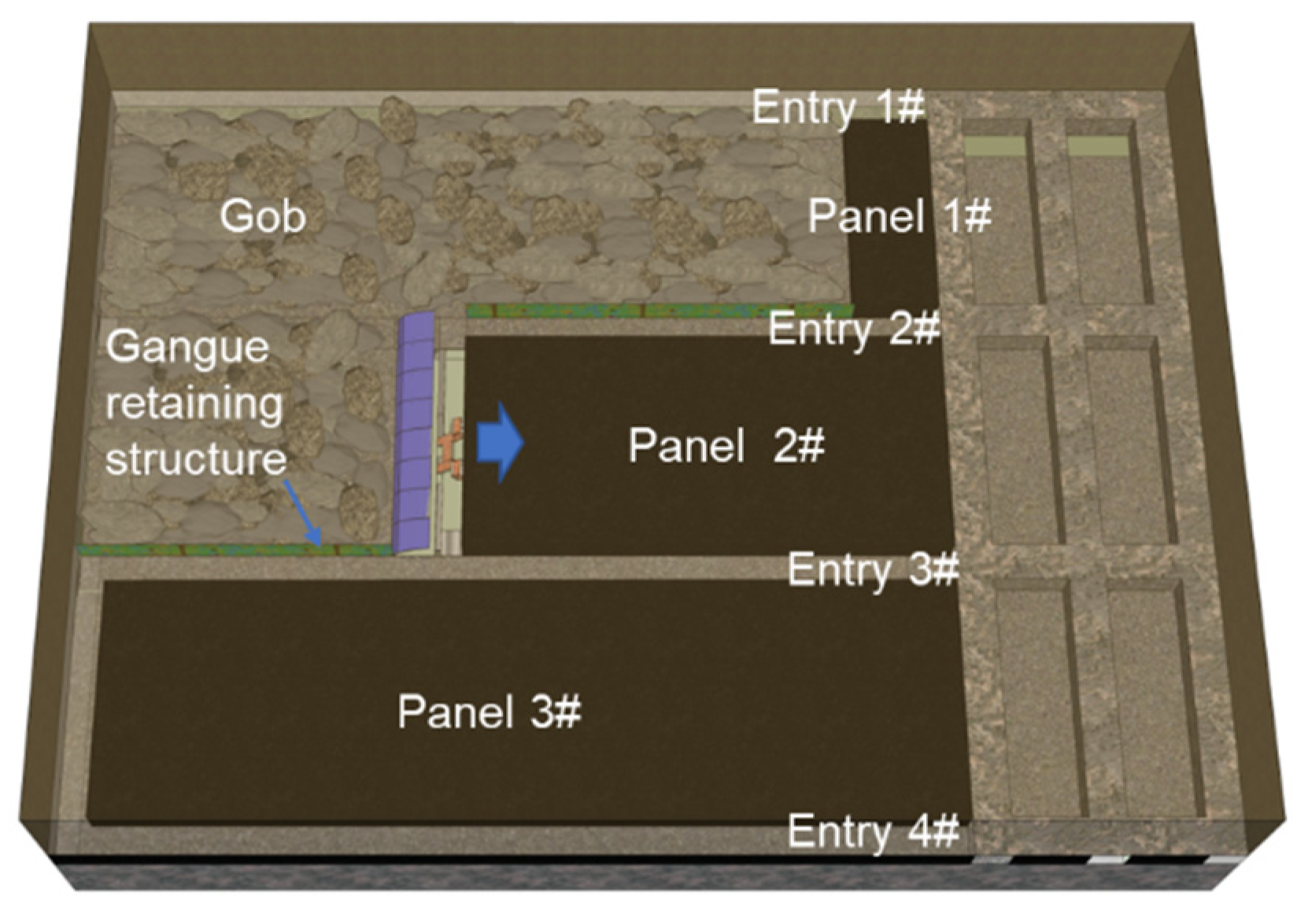
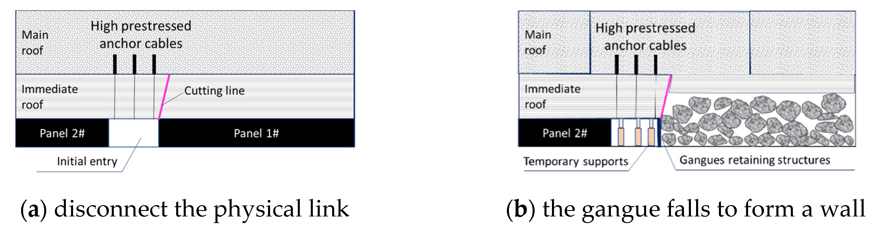
2.1. Brief Description of the GERRC

The GERRC does not require artificial backfill bodies to maintain the balance of the roof, unlike the GERF or other conventional gob-side entry retention methods. A potentially useful highway will be shielded by special technology, as seen in Figure 1, when one of the working faces is being mined in order to prevent damage and keep it in use when mining the following working face. As a result, it is no longer necessary to install special coal pillars to guard mining roadways, which increases resource use and, in theory, increases resource recovery rate to 100%. Additionally, the panel’s total amount of roadway excavation is lowered by 50%, which significantly lowers the cost of excavation. However, maintaining the associated roadways safely while mining is essential to the technology’s success. This is an important topic that will be covered in more detail later in this paper, including the GERRC-related roof pressure relief technique.
Figure 2 shows the different characteristics of the gob-side entry’s surrounding rock structure at various stages of mining. Prior to mining the working face, specific technologies should be used to physically break the link between the roadway roof and the working face roof. Figure 2a depicts the condition of the surrounding rock structure at this period. In order to actively reinforce the support of the roadway roof throughout this operation and increase the stability of the surrounding rock, high prestressed anchor cables must also be used. The length of the anchor cable must be greater than the thickness of the immediate roof, and ensure that the immediate roof is firmly anchored.
A number of vertical temporary supports are placed in the interior of the gob-side entry to support the temporary dynamic loads while the working face is being mined. These supports can also help the anchor cables to increase the stability of the surrounding rock of the roadway. The structural state of the surrounding rocks can then be characterized by Figure 2b after the overlying rock layer of the goaf swiftly collapses to produce gangue with various sizes and naturally forms a wall beneath the support of the protective structures. Once the rock movement in the gob has stabilized over time, the roadway may be securely maintained, and all temporary supports can be taken down. Figure 2c illustrates the final state of the surrounding rock structure.
The next step is to think about how to safely sever the physical link between the roadway roof and the gob roof. This is a significant factor and one of the key topics that will be covered in this paper.

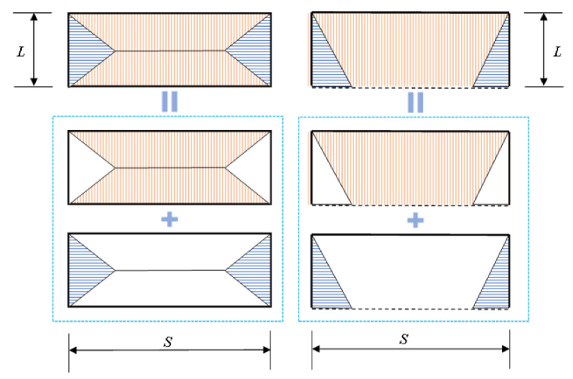
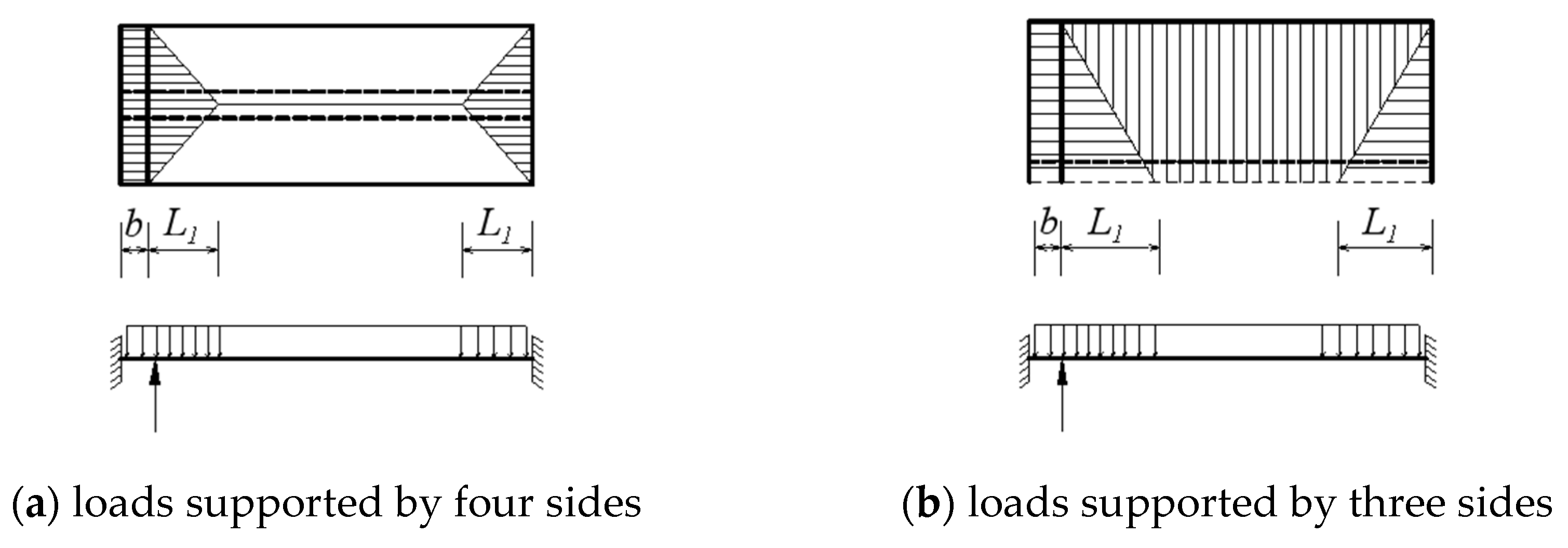
2.2. Loads Division Method

It is commonly known that the roof of a coal seam is typically sedimentary rock with a layered structure; therefore, before the roof is broken, it can be thought of as a layered plate structure. The rock strata can be thought of as a rectangular plate supported by four sides prior to the initial caving of the roof, but during periodic caving it should be thought of as a rectangular plate supported by three sides. The load of the roof rock layer under the two supporting states can be divided according to Figure 3, in accordance with the results of the elastic-plastic mechanics theory calculations, where the shaded area denotes the load from the overlaying rock layer. The working face length S is typically significantly longer than the roof weighting step L.
The gob-side roadway is usually only related to the triangular distributed load in Figure 3, so if the roof pressure step and the characteristic length of the triangle along the working face are determined, the mechanical relationship of the roadway roof will be clear. Assuming that the uniform load of the roof is q, the mechanical model is established as shown in Figure 4a,b after dividing the roof load according to the above load method. It can be seen that in either case, the structural form and stress of the strip plate are the same, so a unified mechanical model can be established as shown in Figure 4c. In the figure, b is the width of the roadway and LI is the length of the key block.

3. Results

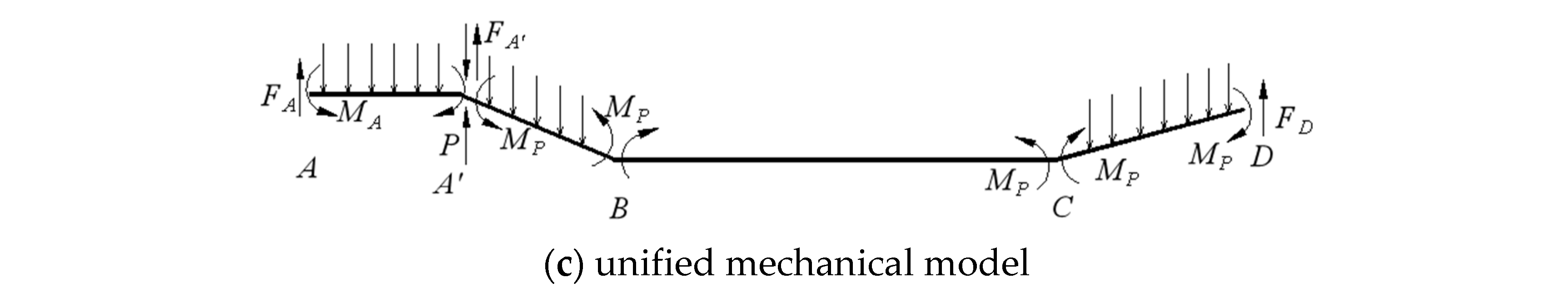
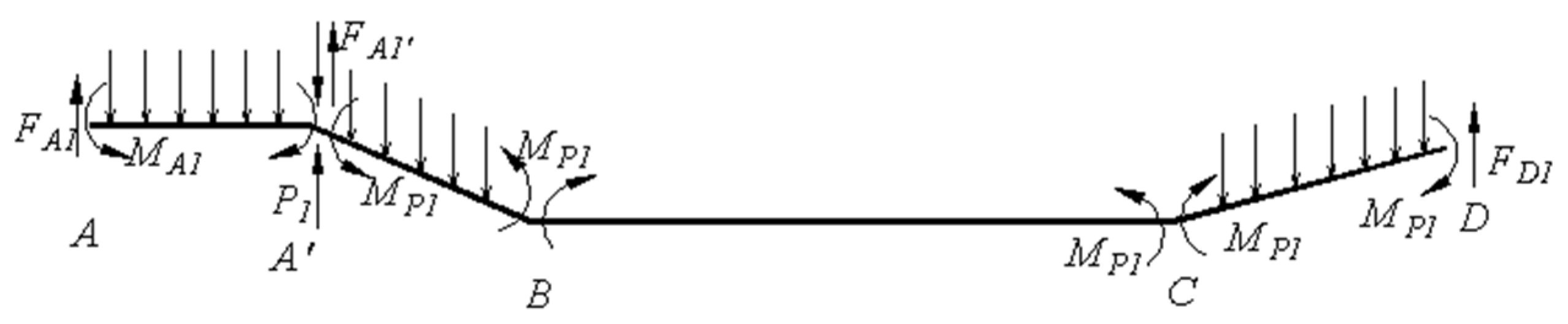
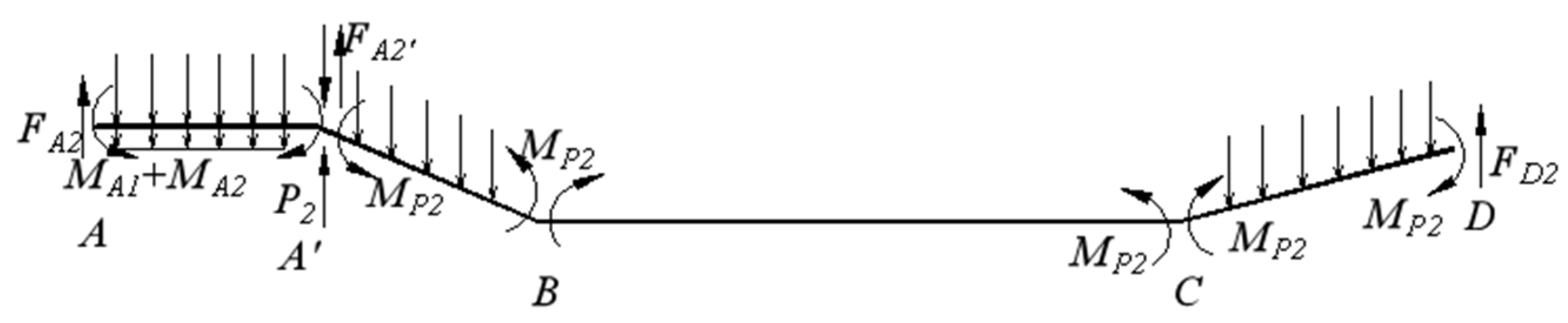
3.1. Mechanical Equilibrium Equation

The mechanical balance approach can be used to examine the mechanical model and determine how the supporting structure interacts with the nearby rock. The collapsing rock mass can fill the goaf under the effect of the surge typical when all of the m roof strata are cracked, as depicted in Figure 5.
Then, the stress of the first layer of rock can be simplified as shown in Figure 6.
Obviously, the following three equations can be obtained according to the static equilibrium condition for A′B and AA′.
F A 1 q 1 L 1 = 0
2 M P 1 1 2 q 1 L 1 2 = 0
M A 1 M p 1 F A 1 b 1 2 q 1 b 2 + P 1 b = 0
Thus, the support resistance of temporary support structure P1 can be obtained:
P 1 = ( M p 1 M A 1 ) b + q 1 L 1 + 1 2 q 1 b
Let q1 = γ1h1, then P1 can be rewritten as
P 1 = ( M p 1 M A 1 ) b + λ 1 h 1 L 1 + 1 2 q 1 b
where, FA is the vertical shear force generated at A by the broken rock stratum, L1 is the characteristic length of rock fracture, and it is determined by geometric information and mechanical parameters of the rock stratum, MP1 is the residual moment, MA1 is the bending moment, γ1 is the bulk density of rock stratum, b is the width of the gob-side entry, and h1 is the thickness of rock stratum.
Similarly, the stress of the second layer of rock can be simplified as shown in Figure 7.
The following three equations can be obtained according to the static equilibrium condition for A′B and AA′.
F A 2 γ 2 h 2 L 2 = 0
M A 1 + M A 2 + P 2 b M p 2 1 2 γ 2 h 2 ( b + h 1 tan β 1 ) 2 1 2 γ 1 h 1 b 2 F A 2 ( b + h 1 tan β 1 ) F A 1 b = 0
where, β is the fracture angle of the rock stratum.
The Equation (7) can be rewritten as
P 2 b = 1 2 γ 2 h 2 ( b + h 1 tan β 1 ) 2 + 1 2 γ 1 h 1 b 2 + F A 2 ( b + h 1 tan β 1 ) + F A 1 b ( M A 1 + M A 2 ) + M p 2 = 1 2 i = 1 2 γ i h i ( b + j = 0 i h j tan β j ) + i = 1 2 F A i ( b + j = 0 i h j tan β j ) + M p 2 i = 1 2 M A i
Obviously, according to the above rule, the following formula can be easily obtained.
P m b + i = 1 m M A i = 1 2 i = 1 m γ i h i ( b + j = 0 i h j tan β j ) + i = 1 m F A i ( b + j = 0 i h j tan β j ) + M p m
Equation (9) can be explained in two parts. To begin with, Pmb indicates the external support resistance that needs to be provided alongside the lane. i = 1 m M A i means the total bending moment of the m-layer rock at point A. It indicates the self-bearing capacity of the surrounding rock, which helps the support structure to carry the load, forming a joint support-rock bearing system. The stronger the self-bearing capacity of the surrounding rock, the smaller the required external structural bearing. Secondly, 1 2 i = 1 m r i h i ( b + j = 0 i h j tan β j ) means the bending moment caused by the residual boundary self-weight of the top slab rock, i = 1 m F A i ( b + j = 0 i h j tan β j ) indicates the bending moment generated by the shear force of the broken rock at the fracture line of the top slab, and Mpm is the ultimate bending moment of the mth layer rock, which is related to the integrity of the rock formation. Under certain mining geological conditions, when the width of the roadway (b) is certain, 1 2 i = 1 m r i h i ( b + j = 0 i h j tan β j ) is constant; i = 1 m F A i ( b + j = 0 i h j tan β j ) is mainly affected by the downward shear force when the rock layer on the roof of the mining area is fractured, if the rock layer is cut off and collapses immediately, and the rock layer on the roof of the mining area has been fractured will lose contact with the residual boundary, and the value of this item is zero; Mpm is the residual bending moment of the mth layer of rock, the size of which is related to the degree of damage to the rock layer, and if the rock layer is completely cut off, its value will also be zero.
Obviously, if certain measures are taken for the roof, the values of both i = 1 m F A i ( b + j = 0 i h j tan β j ) and Mpm can be reduced, thus reducing the required support resistance of the roadway. If the load values of these are completely lifted, Equation (9) becomes simple, as shown in Equation (10). This is the mystery of the mechanics of top cutting and pressure relief for the top cutting and retention technique.
P m b + i = 1 m M A i = 1 2 i = 1 m γ i h i ( b + j = 0 i h j tan β j )

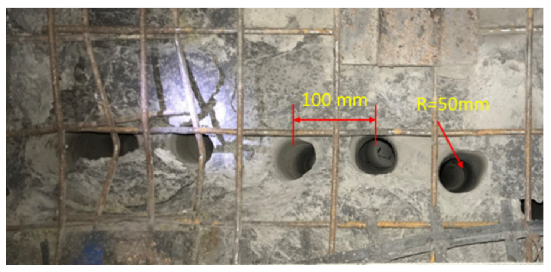
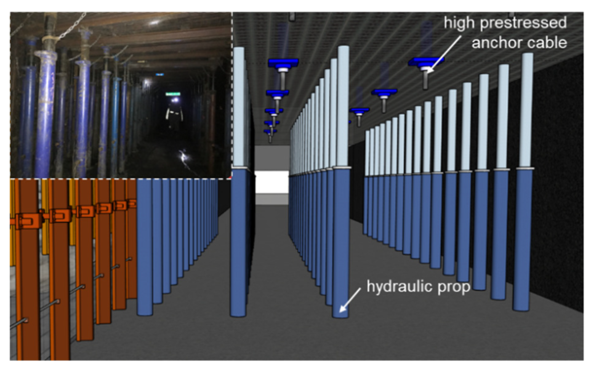
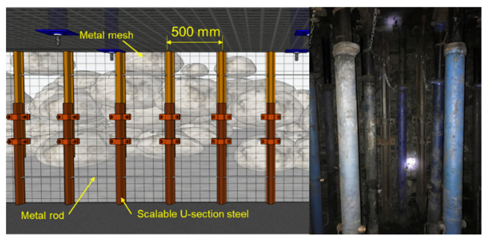
3.2. Implementation Technology fo Pressure Release

The idea of roof-cutting and maintaining the roadway, as was covered in the previous chapter, is to reduce the value of the ultimate bending moment by releasing some of the stresses. The ultimate bending moment is significantly decreased if it is possible to totally remove the roof or partially remove a portion of the roof between the gob and roadway. This condition occurs as a result of the rock’s deterioration, which must have reduced the maximum load it could support. Using the concentrated energy blasting technique is the principal method of cutting the roof rock. Figure 8 depicts the layout of the blast holes for cutting the roof. Figure 9 illustrates the concentrated energy blasting technology’s basic operating principle. In order to create a pre-cracked surface by tension fracture of the roof rock along the set direction, this technology uses a concentrating energy device in the blast hole to produce a concentrated energy effect on the blast products. This results in a strong concentrating energy flow being formed in the set direction and a tensile stress being concentrated in the roof rock. The blast stress wave and explosive gas seek out space after the detonation of the packet in the concentrating energy blasting device in order to liberate energy. Roof rock is sliced in a specific direction under the control of the focusing energy device’s stress wave and explosive gas explosion energy.
Concentrated energy blasting technology has been applied to engineering practice many times, and the authors of this paper have also extensively studied and applied. However, now there is a serious problem: emulsion explosives are banned by the government in many areas of China. This makes it difficult for many mines to obtain enough explosives to perform blasting, making it impossible to implement this advanced pillarless mining technology in many cases. In addition, the amount of emulsion explosive consumed in this way is huge. Generally, each blasting hole needs to consume more than 3 kg of explosives, and it also increases with the depth of the blasting hole. This paper proposes a new alternative, the dense hole-cutting technique, which cleverly bypasses the use of explosives.
As shown in Figure 10, the dense hole roof-cutting technology does not completely cut off the rock formation, but only makes it possible to weaken the integrity of the rock formation as much as possible and reduce the ultimate bending moment value by increasing the spacing between boreholes. One of the extreme cases is that the boreholes are so close to each other that the roof rock is completely cut off. However, it is not necessary to do this, because the workload would be very large, and in practice it is very uneconomical and irrational. Obviously, we need to find a balance point to ensure that we can weaken the roof rock to the point where it can be easily broken off and the workload is not too much. This can of course be achieved by some theoretical analysis to obtain a calculation formula for the best spacing between boreholes. Obviously, though, it is more obvious and straightforward to find this through many iterations in the field, and it also avoids the error between the actual situation in the field and the ideal conditions.

3.3. Engineering Verification

The Ruineng coal mine is located in the northern part of China and has previously used the concentrated blasting technology to achieve non-pillar mining by cutting the roof and retaining the roadway. However, because of the local government’s control of explosives, the concentrated blasting technology could no longer be implemented. In order to continue to promote the roof-cutting technology, the dense hole roof-cutting technology was tried and tested in the field. As shown in Figure 11, there are two working faces, namely working face 116 and working face 118, where working face 116 is mined first. In order to achieve non-pillar mining, when mining the 116 working face, the air return roadway needs to be reserved for the 118 working face, and here, the dense hole roof-cutting technology is used. The regional geology of the 116 working face and 118 working face is shown in Table 1.
As shown in Figure 12, a row of densely cut holes was drilled on the side of the air return roadway against the 116 working face. The parameters of the holes are shown in Table 2.
During the construction of intensive holes, the roof of the roadway was supported, and the support parameters are shown in Figure 13. In order to ensure that the gangue falling down from the gob forms a wall, a protection system consisting of hydraulic pillars, retractable U-steel and reinforcing mesh is set up below the roadway borehole for protection, as shown in the Figure 14.
In order to evaluate the effect of using the intensive drill hole roof cutting technology, a set of observation points were set up every 50 m in the stay-alley section of the air return roadway. The measurement points were mainly designed to monitor the displacement of the roof in roadway as the working face was mined. The measurement data were updated at least once a day by using a laser rangefinder. The monitoring data are shown in Figure 15. The data analysis concluded that the roadway is basically in a stable state when the working face is mined for about 40 days.
The roadway was well formed during the construction on site, as shown in Figure 16. It remained stable while mining 118 working face and achieved the experimental effect, indicating that the dense pressure-released holes roof-cutting technology is safe, reliable, and feasible, and must have promotion value in the future.

4. Conclusions

(1)
The derived mechanical balance equation shows that the surrounding rock of the gob-side entry and the external support structure are coupled. When the surrounding rock has good integrity and high strength, the external support resistance can be appropriately reduced. On the contrary, because the bearing capacity of the surrounding rock is limited, the external support resistance must be increased to keep the surrounding rock in a stable state. At the same time, the equilibrium equation also explains the mechanical principle of surrounding rock pressure release.
(2)
In fact, according to the balance equation, there are many methods to achieve the purpose of surrounding rock pressure release, such as blasting, mechanical cutting, drilling, etc., but practice shows that dense drilling may be one of the safest, most reliable, and most feasible methods because it has the advantages of a simple process and safe operation, and does not need very complex and expensive mechanical equipment.
(3)
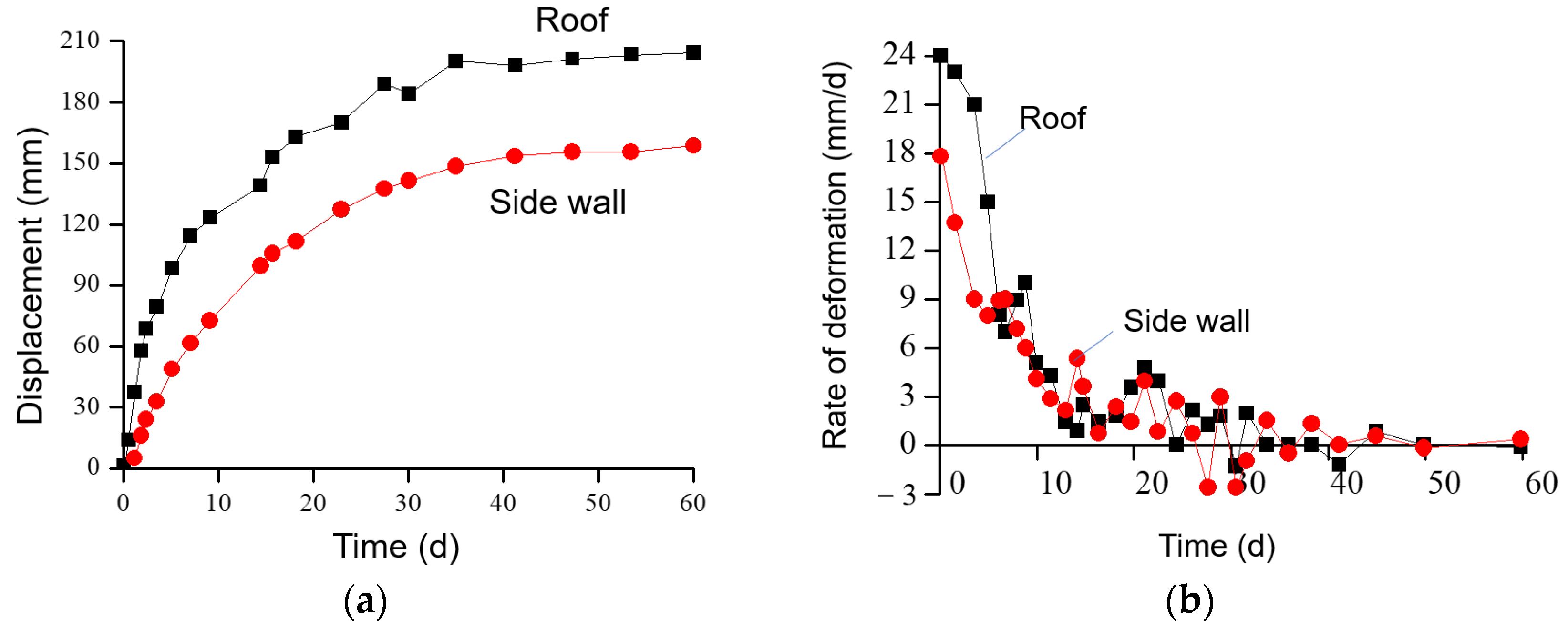
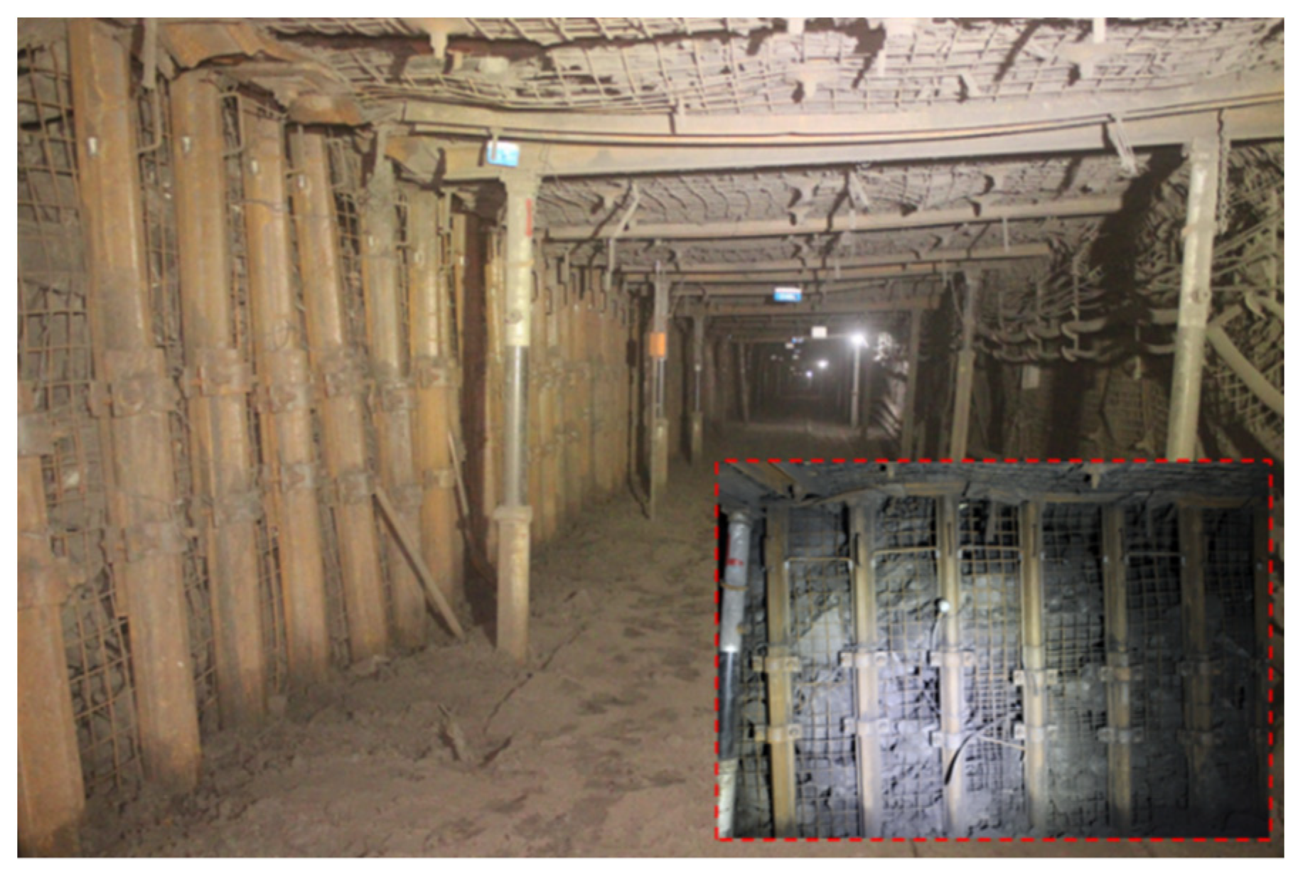
The engineering test results in Ruineng Coal Mine show that the GERRC technology can be fully realized through intensive drilling technology. The measurement results show that the deformation of the roadway is very small, the maximum deformation of the roof is only about 200 mm, and the maximum deformation of the side wall is only about 150 mm, which ensures the safety of the roadway.

5. Discussion

The GERRC involves a new coal mining and roadway retaining technology. In this paper, by establishing a mechanical model, the balance equation of surrounding rock of gob side entry is derived, and the mechanical mechanism of surrounding rock pressure release is obtained by analyzing this equation. Furthermore, this paper proposes to achieve the goal of surrounding rock pressure release through intensive drilling, which is one of the pressure release methods that the GERRC must adopt. In fact, explosives are hazardous products with significant potential for safety risks. Explosives may eventually leave the coal mining industry as a result of the Chinese government’s growing severe regulation of them. Studying the explosive-free method for relieving roof pressure is therefore crucial. The pressure relief method based on dense boreholes that is suggested in this research has significant importance for GERRC’s further promotion.
In previous studies and tests, blasting technology is almost the only way to relieve roof pressure. Sometimes, it does not even take any method to relieve roof pressure, and only relies on the vertical support structure in the roadway (such as single hydraulic prop, manual filling wall, hydraulic support, etc.) to force the roadway to maintain stability. In this way, huge surrounding rock pressure is caused, and the stability of the roadway is difficult to guarantee.
However, the pressure relief based on dense holes still has a lot of practical challenges that need to be further researched, including determining the size and spacing of the holes, creating quick drilling equipment, and ensuring the drilling angle. In this article, only one mine is selected for test, so its geological applicability needs to be further verified in other, different mines. More interesting research in the future may be able to develop some efficient, safe, and reliable drilling equipment, so that the construction efficiency can be greatly improved and the safety of workers can be better guaranteed.

Author Contributions

Conceptualization, Z.Z.; methodology, Z.Z. and M.D.; software, C.X.; validation, M.D. and Z.Z.; formal analysis, Z.Z.; investigation, C.X., H.Y. and W.H.; resources, H.Y. and W.H.; data curation, C.X.; writing—original draft preparation, Z.Z. and M.D.; writing—review and editing, Z.Z., M.D., C.X., H.Y. and W.H.; visualization, C.X.; supervision, H.Y.; project administration, H.Y., and W.H.; funding acquisition, Z.Z. and M.D. All authors have read and agreed to the published version of the manuscript.

Funding

This research was funded by the Open-end Research Fund of State Key Laboratory for Geomechanics and Deep Underground Engineering [SKLGDUEK2024] and the National Natural Science Foundation of China [52108371], and the APC was funded by the National Natural Science Foundation of China [52108371].

Conflicts of Interest

The authors declare no conflict of interest.

References

  1. Zhang, L.; Wang, J.; Feng, Y. Life cycle assessment of opencast coal mine production: A case study in Yimin mining area in China. Environ. Sci. Pollut. Res. 2018, 25, 8475–8486. [Google Scholar] [CrossRef]
  2. Zhu, Z.; He, M.; Wang, X.; Yuan, H. Mechanical Model and Control Technology of Roadside Gangues in Gob-Side Entry Retaining by Roof Cutting. Geotech. Geol. Eng. 2019, 38, 849–860. [Google Scholar] [CrossRef]
  3. Ju, J.; Xu, J.; Zhu, W. Longwall chock sudden closure incident below coal pillar of adjacent upper mined coal seam under shallow cover in the Shendong coalfield. Int. J. Rock Mech. Min. Sci. 2015, 77, 192–201. [Google Scholar] [CrossRef]
  4. Lolon, S.A.; Brune, J.F.; Bogin, G.E.; Grubb, J.W.; Saki, S.A.; Juganda, A. Computational fluid dynamics simulation on the longwall gob breathing. Int. J. Min. Sci. Technol. 2017, 27, 185–189. [Google Scholar] [CrossRef]
  5. Hua, X.Z. Development status and improved proposals on gob-side entry retaining support technology in China. Coal Sci. Technol. 2006, 34, 78–81. [Google Scholar]
  6. Luan, H.; Jiang, Y.; Lin, H.; Li, G. Development of a New Gob-Side Entry-Retaining Approach and Its Application. Sustainability 2018, 10, 470. [Google Scholar] [CrossRef] [Green Version]
  7. Kan, J.G.; Wu, J.K.; Zhang, N.; Liang, D.X. Structure stability analysis and control technology of surrounding rock of the secondary gob-side entry retaining. J. Min. Saf. Eng. 2018, 35, 877–884. [Google Scholar] [CrossRef]
  8. Cheng, Z.H.; Qi, Q.X.; Kong, W.Y.; Zhang, L.; Ji, W.B.; Liu, X.G. Study on the reasonable layout of gob-side remained gateway of lower coal seam close to coal seam group. J. Min. Saf. Eng. 2015, 32, 454–458. [Google Scholar] [CrossRef]
  9. Podkopaiev, S.; Gogo, V.; Yefremov, I.; Kipko, O.; Iordanov, I.; Simonova, Y. Phenomena of stability of the coal seam roof with a yielding support. Min. Miner. Deposits 2019, 13, 28–41. [Google Scholar] [CrossRef]
  10. Iordanov, I.; Novikova, Y.; Simonova, Y.; Yefremov, O.; Podkopayev, Y.; Korol, A. Experimental characteristics for deformation properties of backfill mass. Min. Miner. Deposits 2020, 14, 119–127. [Google Scholar] [CrossRef]
  11. Petlovanyi, M.; Malashkevych, D.; Sai, K.; Bulat, I.; Popovych, V. Granulometric composition research of mine rocks as a material for backfilling the mined-out area in coal mines. Min. Miner. Deposits 2021, 15, 122–129. [Google Scholar] [CrossRef]
  12. Tang, J.X.; Hu, H.; Tu, X.D.; Deng, Y.H. Experimental on roadside packing gob-side entry retaining for ordinary concrete. J. China Coal Soc. 2010, 35, 1425–1429. [Google Scholar] [CrossRef]
  13. Li, T.; Chen, G.B.; Qin, Z.C.; Li, Q.H.; Cao, B.; Liu, Y.L. The gob-side entry retaining with the high-water filling material in Xin’an Coal Mine. Geomech. Eng. 2020, 22, 541–552. [Google Scholar] [CrossRef]
  14. Du, Z.; Chen, S.; Ma, J.; Guo, Z.; Yin, D. Gob-Side Entry Retaining Involving Bag Filling Material for Support Wall Construction. Sustainability 2020, 12, 6353. [Google Scholar] [CrossRef]
  15. Khairutdinov, A.; Ubysz, A.; Adigamov, A. The concept of geotechnology with a backfill is the path of integrated development of the subsoil. IOP Conf. Ser. Earth Environ. Sci. 2021, 684, 012007. [Google Scholar] [CrossRef]
  16. Rybak, J.; Kongar-Syuryun, C.; Tyulyaeva, Y.; Khayrutdinov, A.M. Creation of Backfill Materials Based on Industrial Waste. Minerals 2021, 11, 739. [Google Scholar] [CrossRef]
  17. Huang, W.P.; Gao, Y.F.; Wen, Z.Z.; Gao, L. Technology of gob-side entry retaining using concrete-filled steel tubular column as roadside supporting. J. China Univ. Min. Technol. 2015, 44, 604–611. [Google Scholar]
  18. Hua, X.Z.; Ma, J.F.; Xu, T.J. Study on controlling mechanism of surrounding rocks of gob-side entry with combination of roadside reinforced cable supporting and roadway bolt supporting, and its application. Chin. J. Rock Mech. Eng. 2005, 24, 2107–2112. [Google Scholar]
  19. Batugin, A.; Wang, Z.; Su, Z.; Sidikovna, S.S. Combined support mechanism of rock bolts and anchor cables for adjacent roadways in the external staggered split-level panel layout. Int. J. Coal Sci. Technol. 2021, 8, 659–673. [Google Scholar] [CrossRef]
  20. Han, C.L.; Zhang, N.; Li, B.Y.; Si, G.Y.; Zheng, X.G. Pressure relief and structure stability mechanism of hard roof for gob-side entry retaining. J. Cent. South Univ. 2015, 22, 4445–4455. [Google Scholar] [CrossRef]
  21. Sun, Q.; Zhang, J.X.; Huang, Y.L.; Yin, W. Failure mechanism and deformation characteristics of gob-side entry retaining in solid backfill mining: A case study. Nat. Resour. Res. 2019, 29, 2513–2527. [Google Scholar] [CrossRef]
  22. Eremenko, V.A.; Galchenko, Y.P.; Lipnitskiy, N.A.; Umarov, A.R. Frame mine structure for underground mining of thick ore bodies. Gornyi Zhurnal. 2021, 9, 11–18. [Google Scholar] [CrossRef]
  23. Cao, S.G.; Chen, X.Z.; Yang, H.Y.; Wang, S.; Zou, D.J. Analysis on roadway control technology of gob-side entry retaining and applicable conditions. Coal Sci. Technol. 2016, 44, 27–33. [Google Scholar] [CrossRef]
  24. He, M.C.; Zhu, G.L.; Guo, Z.B. Longwall mining “cutting cantilever beam theory” and 110 mining method in China: The third mining science innovation. J. Rock Mech. Geotech. Eng. 2015, 7, 483–492. [Google Scholar] [CrossRef] [Green Version]
  25. Liu, J.; He, M.; Guo, S.; Li, J.; Zhou, P.; Zhu, Z. Study on characteristics of pressure relief by roof cutting under nonpillar-mining approach. Bull. Eng. Geol. Environ. 2022, 81, 441. [Google Scholar] [CrossRef]
  26. Liu, J.; He, M.; Ming, C.; Zhang, J.; Yang, G.; Guo, L.; Guo, S.; Rodriguez-Dono, A.; Zhu, Z. Study on the bearing characteristics of random lumpiness gangue from a gob roof. Bull. Eng. Geol. Environ. 2022, 81, 406. [Google Scholar] [CrossRef]
Figure 1. Layout of working faces and roadways for the GERRC.
Processes 10 02629 g001
Figure 2. Evolution processes of surrounding rock structure.
Processes 10 02629 g002aProcesses 10 02629 g002b
Figure 3. Load division of roof rock layer.
Processes 10 02629 g003
Figure 4. Mechanical model of strip plate.
Processes 10 02629 g004aProcesses 10 02629 g004b
Figure 5. Fracture form of roof.
Processes 10 02629 g005
Figure 6. The mechanical model of the first layer of roof.
Processes 10 02629 g006
Figure 7. The mechanical model of the second layer of roof.
Processes 10 02629 g007
Figure 8. Layout of roof cutting blast holes.
Processes 10 02629 g008
Figure 9. Principle of concentrated energy blasting technology.
Processes 10 02629 g009
Figure 10. Layout of dense pressure-released holes.
Processes 10 02629 g010
Figure 11. Schematic layout of working face.
Processes 10 02629 g011
Figure 12. Field layout of the dense pressure-released holes.
Processes 10 02629 g012
Figure 13. Roadway support parameters.
Processes 10 02629 g013
Figure 14. Schematic diagram of gangue protection system.
Processes 10 02629 g014
Figure 15. Field monitoring results. (a) Roadway deformation monitoring results; (b) roadway deformation rate monitoring results.
Processes 10 02629 g015
Figure 16. Field application effect.
Processes 10 02629 g016
Table 1. Regional lithological situation.
NameLithologyThickness (m)
Main roofFine-grained sandstone with mudstone13.87~18.19
Immediate roofMudstone1.65~2.3
Immediate floorMudstone0.72~2.68
Table 2. Design parameters for the dense pressure-released holes.
Spacing of Holes/mmDiameter of Holes/mmDepth of Holes (m)
5010010.3
Publisher’s Note: MDPI stays neutral with regard to jurisdictional claims in published maps and institutional affiliations.

