Abstract
This paper presents a simulation of an insulated micro-grid system based on the three-level converters control for energy management. Different renewable power sources (wind turbine and Photovoltaic (PV) energy systems) are used to energize the micro-grid. However, a battery energy storage system (BESS) and a variable diesel generator are also used to improve the reliability of the system. The contribution of this research is focused on the power control method based on improving the quality of energy transfer, mastering dynamic interactions and maximum energy production from renewable energies to reduce the fuel consumption by the diesel. Firstly, the proposed control model for each renewable energy was carried out through simulation in the environments of Matlab and Simulink to test the robustness and performance. The second part of this research is dedicated to managing the sharing of power between load, generators, and storage systems by extracting the references of power. The three-level PWM rectifiers for variable speed diesel generators was used to maintain and control the DC bus voltage of the isolated micro-grid. The results obtained from simulations show a good correlation between static and dynamic systems even for fluctuating sun power and wind speed.
1. Introduction
In the context of energy transition, thermal power stations are destined either to disappear or to evolve towards a more environmentally respectful model. Major energy and technological challenges, which found its answer in the hybrid micro-power plant. This new generation of power plant, which can couple the activity of a diesel generator with one or more renewable energy production units and possible storage units, is attracting more and more attention. Hybrid power plants combine two or more different energy types, and some of them include conventional energy sources, such as diesel generators and renewable energy with/without storage systems.
Photovoltaic and wind turbine systems play a main role in energy transitions and provide more than half of the renewable generation in the world [1]. According to same references, the hydroelectrical energy is considered to be an important renewable energy that supplies 17% of the total global power generation and is the third-largest source. The hybrid micro-power plant, the PV, and/or wind turbine systems combined with a diesel generator, are frequently present in hot areas. In the city of Santa Rosa, RS, Brazil, renewable energy hybrid systems have been used to provide power for the pumping station [2]. The hybrid energy systems consist of three sources, PV, wind and diesel, which have been simulated by HOMER as three cases: an isolated PV-wind system; an isolated PV-wind-DG system; and a grid-connected PV-DG system. In [3], operational planning and energy management system tools were developed to study the urban micro-grid, consisting of PV, a small gas turbine, a battery storage system, and load demand. The compensation of reactive power and transient stability issues has been studied for hybrid systems (PV–wind–DG) using mode of fuzzy-sliding [4]. The unified power flow controller (UPFC) was implemented to increase the voltage stability for the synchronous generator in the hybrid energy system. The optimal configuration of a hybrid system (PV–wind–DG) has been investigated for remote off-grid Peruvian villages in Peru [5]. HOMER software was utilized for seven configurations to minimize the cost to determine the optimal size. An optimal tool based on an agent-based model and meta heuristic optimization technique was used to optimize the capacity of PV and storage units integrated into grid [6]. Cost and reliability of hybrid system consist of PV–wind–biomass sources were the main objectives of the optimization method based on genetic and annealing algorithms in [7]. The results of these proposed algorithms are compared with a grey wolf optimizer (GWO) to satisfy the design requirement.
The hybrid plant can integrate storage energy devices, such as supercapacitors and/or batteries, to allow a significant reduction for fuel consumed by a diesel generator. The battery energy storage system (BESS) is used with (DG) set in a standalone micro-grid to maintain the hybrid system reliability [8]. Different optimization techniques have been utilized for hybrid energy systems with storage to test different cases. In [9], a particle swarm optimization technique has been applied to find the optimal size of generation/storage system. The cost of energy was considered as an objective function to determine the number of batteries, PV, wind turbines, and DG based on social spider technique in [10] and the analytical technique in [11]. Additionally, the minimization of operation costs has been investigated in [12] by determining the optimal power flow, taking into account the state of charge of the battery and variation of load demand. In India, several cases have been studied to find the optimal size of hybrid systems (PV–wind–DG–batteries) by using HOMER in [13]. In the residential case study, nine scenarios based on hybrid converter system with PV–wind–DG–BSS were investigated to minimize the total net present cost and greenhouse gas (GHG) [14]. In [15], the multilevel boost converter (MBC) was used for the PV system to extract maximum power and the line commutated inverter (LCI) was adjusted to control the charge and discharge of battery.
However, most of these researchers focused on one of the three main objectives: management, optimization, and control. The combination of two or all of these objectives has been given less attention and creates new challenges to address more complexity for the system. On the other hand, using simulated models such as HOMER can simplify the design task, but mostly with some limitations. To overcome these shortcomings, the simulation of the system was designed under the Simulink environment to represent the performance of the sources, converters, and load with different profiles. The combination of controlling the system by using the three-level converters with the power management challenges has been presented. The real collected data for irradiation and wind energy was used to apply for this simulation and will be applied to real experimental equipment in the future work.
In this work, the more important challenges that face the hybrid micro-power plants with renewable energy sources were considered. These challenges include improving the quality of energy transfer, mastering dynamic interactions, maximizing the life of the sub-systems and reducing fuel consumption. The main contribution of this research is to control and manage the proposed insulated micro-grid (PV–wind–DG–BSS). Three-level converters control strategies have been used to achieve the efficient energy management of the overall system. The maximum output power of wind and PV systems has been controlled using the MPPT method and the management of shared energy production has been optimized based on load voltage control.
The organization of this paper starts by presenting the proposed hybrid system configuration in Section 3. In Section 4, the maximum power point tracking (MPPT) control strategies of wind turbines and PV systems based on three level converters are described. Section 5 is devoted to the energy management strategies to optimize the power sharing by controlling the voltage for the load and the DC bus in isolated area. Section 6 is concerned with the control of batteries and DG to maximize the share of storage energies and minimizing the contribution of the variable speed DG with the absence of renewable energy productions. The simulation results are discussed in Section 7 and the concluding remarks are provided in Section 8.
2. Presentation of Hybrid System Structure
The studied hybrid system presented in Figure 1 consists of the renewable energy sources (PV and wind) combined with the lithium-batteries and variable speed diesel generator. The DC bus link is connected to the PV and batteries power source through three-level DC–DC converters. A three-level rectifier was used to connect the wind power source to the three-level converter and diesel generator to DC bus link. The variable load and the DC bus was linked through three-level neutral point clamped (NPC) inverters.
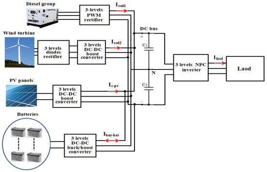
Figure 1.
Hybrid system configuration.
In this paper, the insulated micro-grid proposed consists of various sources: the main source of the system is the diesel generator, the renewable energy system (PV–Wind), and the storage system as backup batteries. The variable speed diesel generator is used to overcome the drawbacks of the fixed speed diesel generator, such as the inefficient use of fuel; the constant sound, regardless of the power level required from the diesel engine; high pollutant emissions even when energy demand is low; and poor frequency and voltage stability in transient phases. The main contribution of the variable speed diesel generator is to operate continuously with or without output current to maintain and control the DC bus voltage. In addition, the proposed energy management of the system is based on three-level power converters because of their conveniences, such as a finer voltage adjustment and a very significant reduction in the rate of the harmonic distortion of the load current when compared to classical two-level converters.
The renewable sources can contribute to providing a greater amount of energy and batteries, which are appropriate for smoothing the long-period fluctuation of power generation due to the wind and solar phenomenon. Three-level converters are used in this paper as a powerful control strategy to improve the energy quality transferred, maximize energy production from renewable energies, allow real time control, and reduce fuel consumption by the diesel.
3. MPPT Power Control strategies
3.1. MPPT Control Strategy for Wind Turbine
During the day, the energy produced by wind turbine changes continually as variation of wind speed. The maximum net power generation take-outs from a wind energy conversion system (WECS) during cut-in wind speed are rated. The MPPT controller of the WECS system tracks the maximum power point (MPP). The control (MPPT) of the wind turbine is based on the production of maximum power from the permanent magnet generator (PMG) using the three-level diode rectifier associated with a three-level double boost converter connected to a DC bus, as presented in Figure 2 [16]. The optimal operation of the system is ensured by using the MPPT technique that allows the extraction of the maximum power generated by the wind turbine [17].
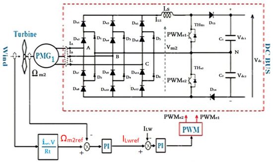
Figure 2.
Wind turbine MPPT control based on the three-level boost converter.
Indeed, for any operating point it is preferred to maximize mechanical power, which corresponds in Equation (1) to the maximum power coefficient Cp(λ, β). This maximum value is achieved if the relative speed λ reaches its optimal point (λopt). This technique is carried out through the speed and torque control loops of the wind turbine (through the control of current). The MPPT control techniques are presented in [18] and the wind turbine model is presented in Equation (1).
where V is the wind speed in [m/s]; β is the wedging angle of the blades; ρ is the air density; is the radius of the wind turbine; S is the circular area swept by the turbine; and is the turbine mechanical power.
3.2. MPPT Control of the PV System
In photovoltaic panels, choosing the suitable controller at a high voltage gain is the main challenge of using a three-level converter (DC–DC boost). An efficient controller is used to ensure the optimal operation and to maintain the constant voltage of the DC link. The main advantages of using the three-level boost converter for PV panel models are the cancellation of the current ripple and reducing the size of the input filter. In three-level DC–DC boost converters (shown in Figure 3), the rate voltage of the switching devices is half of the output voltage—this results in a reduction in cost and increase in the power efficiency.
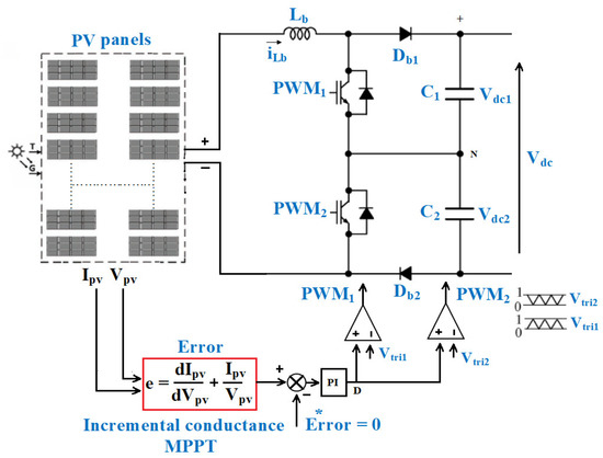
Figure 3.
MPPT control of the PV based on three-level boost converter, where “*” indicate reference of Error.
The MPPT control technique is based on the knowledge of the variation in the conductance of the PV generator and on the position of the operating point relative to the maximum power point [19]. The maximum power can be tracked by making comparisons at all times of the conductance value Ipv/Vpv with that of the conductance increment dIpv/dVpv, as expressed in Equation (2).
Normally, the output voltage is positive from a source. The incremental conductance INC algorithm (that generate reference signal to MPPT) tries to find the voltage operation point where the conductance and incremental conductance are equal, so that in order to bring the operating point to the MPP, the PI controller is used to control the error (the sum of the conductance and the conductance increment) to zero. The output voltage of the regulator allows the generation of the converter control signal by pulse width modulation (PWM), [20].
4. Management Control Strategy
4.1. Load Voltage Control Strategy in Context of Isolated Areas
The micro-grid supplies energy to the load via a three-level NPC inverter. The topology of a three-level NPC consists of four series bidirectional power switches, two midpoint clamped diodes, and four freewheeling diodes for each phase with two equal capacitors. The diode is used to split the voltage by clamping the upper switches from a maximum voltage to zero point on the DC link. Since there are three kinds (positive, negative, and zero) of switching states, the 27 switching states for a three-level inverter corresponds to 27 voltage vectors (3 zero vectors and 24 non-zero vectors). In a complex plane, as shown in Figure 4, the space vector is divided into six sectors, and each of these large sectors is divided into six small sectors.
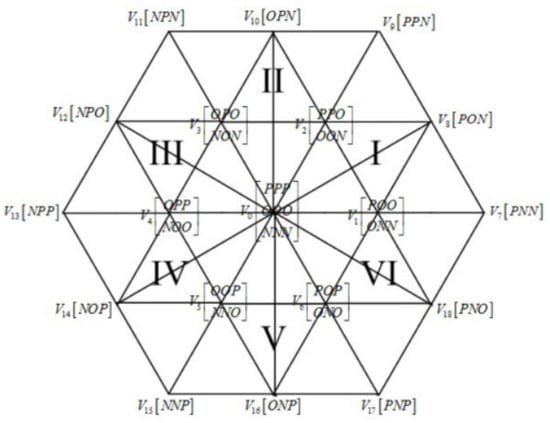
Figure 4.
Vectors of switching state for three level inverter [21].
The root mean square (RMS) voltage control based on the d and q components is used in order to linearize the control as presented in Figure 5. The method of space vector pulse width modulation (SVPWM) is used to generate the control signals (PWM) [22]. This method is based on the balance of the voltages and sets the state of the inverter switch and its on-times. The balance technique has improved the voltage ripples at capacitors in the steady state in addition to generating high quality signals of inverter outputs.
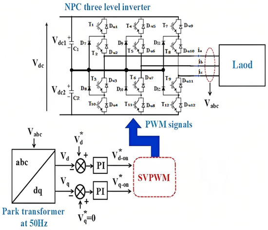
Figure 5.
Load voltage control using three-level NPC inverter and SVPWM, where “*” indicate the references of the Vd and Vq voltages.
4.2. Model of Batteries and Diesel Power References
The main principle of the proposed control strategy is based on sharing the power of load demand between the different renewable energies (wind and PV). In this hybrid system, disturbance interactions appear to be induced by the renewable energy sources and the load at the point of coupling. The control of these dynamic interactions has been proposed by considering the frequency components of the fluctuations. If the voltage of the DC bus is controlled to fix value, the disturbances of the system will be transferred to the value of the currents. The DG and batteries powers references are extracted from the powers produced by the renewable energy sources and the load demand using the low-pass filters (LPF), as shown in Figure 6. Due to profile variances for wind and solar energy in terms of day/night duration; their life cycle, the battery power reference (), the diesel power reference () extracted from the wind power (Pw), the PV power (Ppv), and the load power (Pload) is assigned to batteries.
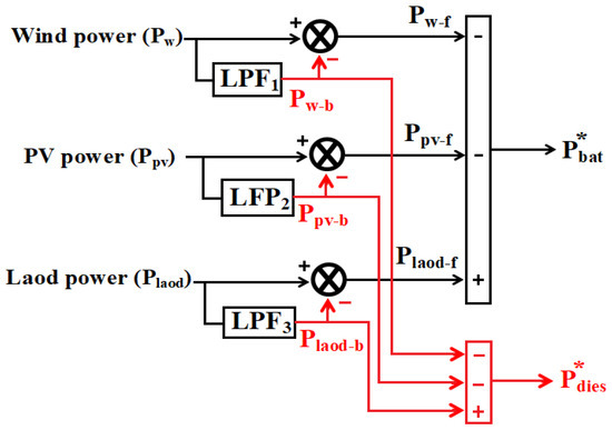
Figure 6.
DG and battery power reference extraction method, where “*” indicate the references of the batteries Pbat and diesel Pdies powers.
The low-pass filter (LPF1-3) approach was used to determine frequency identification, as described in [23]. The obtained frequencies for the PV, wind turbine, and load are 7.9 mHz, 0.32 mHz, and 127 mHz, respectively. The currents of each source and load are broken down into low frequency and high frequency components, where the total high frequency components are utilized to estimate the reference of batteries power and the sum of low frequency components is used to estimate the DG power profile.
5. Control of Storage and Thermal Energy
5.1. Batteries Current Control Strategy
The control sub-system of batteries power includes a battery interfaced with a converter (three-level buck/boost) to control the power flow between the batteries and the DC bus. The type of batteries considered in this research are Li-ion because of their efficiency and high energy density compared with NiMH, lead-acid batteries, or NiCd types. The output voltage of the battery is taken into account as a nonlinear function because it depends on the nonlinear current and battery state of charge (SoC). The battery voltage is found by utilizing the following equation [24].
where is the open circuit voltage, is open circuit current, is battery internal resistance, is battery capacity, is polarization constant, is exponential voltage, is the actual charge current of battery (exponential capacity), and if is the filtered current of battery.
The expression term () is referred to polarization voltage that represents the battery SOC effect on the performance of the battery. The charging and discharging state of batteries play a main role in buffering the fluctuation of power and stabilizing the bus voltage of the micro-grid. The voltage of the battery increases during charging after the battery is full and can be represented by the polarization resistance () that is calculated by:
According to the above parameters, the model of the Li-ion battery can be figured from Equations (3) and (4), as in Figure 7.
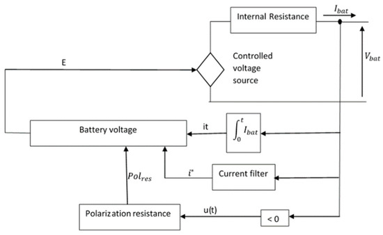
Figure 7.
Model of Li-ion [25].
The control method of the three-level buck/boost converter is based on the batteries’ current management, as presented in Figure 8, where the current reference is calculated from the battery reference power, , given in Figure 6. In order to avoid the destruction of the DC-bus capacitors, the voltage balancing control has been used to produce the , then which is used as the reference for current control, trough PWM signals.
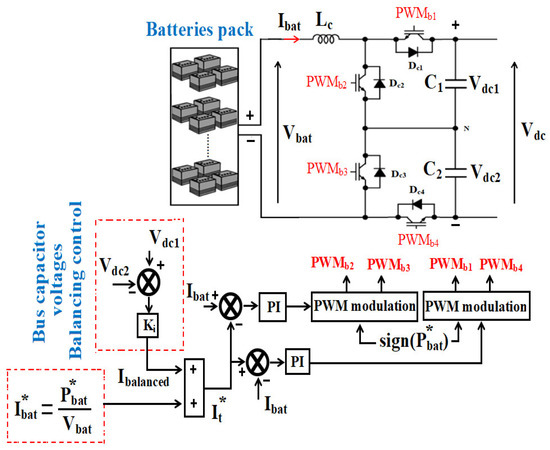
Figure 8.
Battery current control and DC bus capacitor voltage balancing control method.
The bidirectional operation of this converter conditional on the sign of . Thus, if ≤ 0, the batteries charge and the converter is in buck mode. If > 0, the converter works in boost mode and the batteries are discharging. The control signals are phase shifted by 180°, on the one hand, between PWMb2 and PWMb3 and, on the other hand, between PWMb1 and PWMb4 [23].
5.2. Variable Speed Diesel Generator Control Strategy
The variable speed diesel generator (DG) works as a stable power source that allows the maintaining of the DC bus voltage of the micro-grid. In this context, the DG control is based on the speed control of the permanent magnet generator (PMG) and the DC bus voltage control as demonstrated in Figure 9. The control strategy of the PMG speed is simplified, focusing solely on the behavior of the mechanical torque as represented in in Figure 6. The speed control transmitted to the generator by comparing the estimate speed () from the mechanical torque to speed reference ().
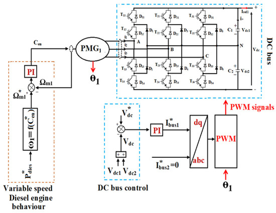
Figure 9.
Three-level PWM rectifier control method.
The DG speed reference extracted from the fuel flow index, rate power, and engine torque parameters are given in Equation (4). The reference torque () depends on the polynomial function of the fuel flow expressed as a function of the diesel generator power. This reference torque is used to estimate the reference speed of the diesel, as presented below:
where represents the index of fuel flow, is the nominal diesel power generator considered to be 20 kW, is the polynomial function to fit the variant gain of engine torque, T1 is the time constant (0.05 s) corresponding to the combustion delay, and T2 corresponds to the change period of engine torque and is considered as a time constant (0.02 s) [26]. The coefficients of the polynomial function of the fuel flow are: = 0.26; = −0.22; = 3.89; = −7.24; = 6.40; and = −2.11.
The DC bus voltage control is achieved through a three-level rectifier PWM vector control with an internal loop based on hysteresis control, as illustrated in Figure 7 [11]. The reference current () is a fixed zero to obtain the unitary power factor, while the reference current () is calculated from the control loop of the DC bus voltage control.
6. Insulated Micro-Grid System Simulation Results
To illustrate the feasibility of the micro-grid system, the Matlab/Simulink software is used to simulate the energy management strategy. The 800 V DC bus supplied by 25 kW diesel generator, 30 kW wind turbine, 22 kW PV arrays, and 65 kW backup batteries. As shown in Figure 1, the three-level DC–DC converter is linked between the power source (PV) and the DC bus link. The wind power source energizes the micro-grid through the three-level rectifier and diesel generator connected to DC bus link by the three-level converter. The storage energy from the pack of batteries with 372 V maximum voltage is controlled by the bidirectional buck-boost converter and the three-level NPC inverter was used to connect the DC bus link to the variable load.
The reference for the DC bus voltage was fixed to 780 V and 890 V, while the load reference voltage on the d-axis was fixed to (400 V and 460 V) and that of the q-axis was fixed to zero. The parameters of DG, wind turbines, PV panels, and cells of Li-ion batteries used in the simulation of micro-grid system are presented in Table 1.

Table 1.
Utilized parameters in micro-grid system simulations.
In order to maintain the power balance in the micro-grid, the hybrid system of wind–PV–DG–batteries has to share power with THE variation load. The power control based on extracting energy sources and battery power reference was used as the control strategy for the proposed system, as shown in Figure 10.
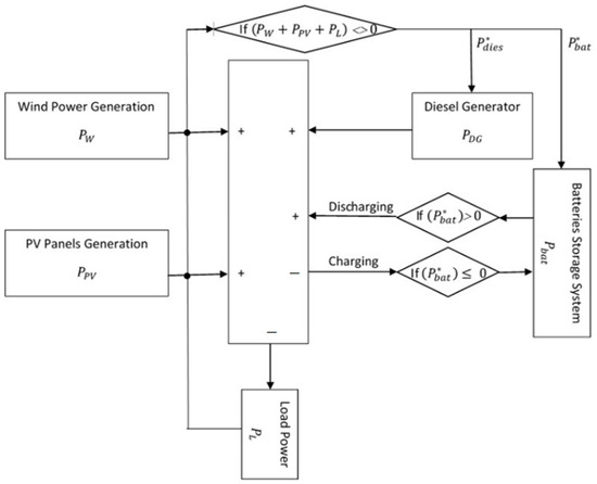
Figure 10.
Management scheme for load sharing.
During the under-generated productions, the power output of the wind turbine system, , and the PV arrays system, , is smaller than the power required by the load . The deficit of power in this status will fluctuate the frequency on the micro-grid that led the power reference for energy sources and batteries to discharge batteries and provide , depending on the deficit power magnitude.
In conditions of over-generation, the power load demand is smaller than power produced by renewable energies ( and PV). The cells of batteries absorb the additional power and store it as storage energy. If the production exceeds the maximum power capacity of the storage batteries, the MPPT control system for PV solar system and the pitch regulation of wind turbine must decrease the output power of wind or PV to improve the voltage stability of the DC bus link.
Under any emergency conditions, such as no power output from PV panels system due to nighttime or no power from the wind turbine generator at low or high wind speeds, the shortage at the load power can be supplied by the DG. In addition, the storage energy in the cells of batteries is also used to keep the voltage of the DC bus link within the limit required.
The energy between the DG sources of the micro-grid has been well managed based on the performance of individual energy resources and the convenient controllers for each of them.
The entire micro-grid has been simulated under different conditions for wind energy, PV solar energy, and variable load. Figure 11 presents the sharing power of PV panels in micro-grid through the DC-bus link, which fluctuates according to the daily irradiance imposed on the solar PV panels. This fluctuation shown in the curve is due to the variations of the clouds during the sunny days from 3h to 15h as illustrated in Fig.11. The waveform reaches maximum values from 8h to 12h as illustrated in Fig.11, where clouds decrease generation to 50% for some minutes. The irradiance solar profile is taken from the supermarket (AUCHAN) in France, while the wind speed profile is taken from the previous research in [27]. The MPPT control technique based on conductance increment is achieved quickly at the operating point location relative to the MPP.
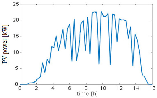
Figure 11.
Power of the PV panels in point of coupling.
The power profile of the wind turbine at the point of coupling for which the micro-grid has been tested is illustrated in Figure 12. Due to the strong variations in the wind speed, the power presents the fluctuations. The initial wind velocity is set at 12 m/s for the system and the cut-in/cut-out is set to be 2.5/25 m/s, respectively. Based Figure 12, the maximum values of the wind velocity reached between 8h to 10h, while at 5h and 14h, the wind velocity dropped to the minimum wind velocity.
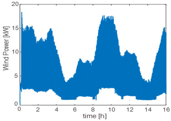
Figure 12.
Power of the wind turbine at the point of coupling.
The evolution of the DG power, as stated by the contributions of the wind turbine and the PV panels with the load demand, is presented in Figure 13. The DG power profile was estimated by using the sum of low frequency components that reflect the evolution of power requirements at the site.
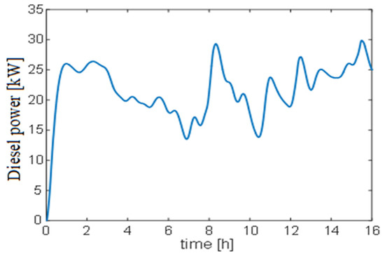
Figure 13.
Power of the diesel generator at the point of coupling.
The variation in load power demand is presented in Figure 14. The minimum and maximum power of load is 22 and 44 kW, respectively, which occurs at approximately 7h (7 a.m.) and 15h (3 p.m.). It shows that the power fluctuations from the renewable energy resources and the load have been compensated by the batteries in order to obtain the best correlation between the transferred energy to the load and the production quality required for the load. The batteries store the excess energy produced when is in the charging status (negative zones) and ensure the recovery of this energy in the discharge status (positive zones).
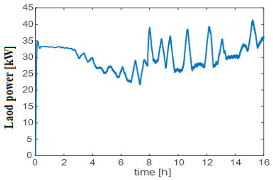
Figure 14.
Power demand of the load.
The load voltage control results are represented in Figure 15, where Vd is close to the reference voltage Vd* and Vq are the same to its reference Vq*. The simulations results show a good concordance between the Vd, Vq and their references, with the percentage of the overshoot errors less than 5%, which means that the control has successfully followed the reference voltage and displays good performance at the transient time. The voltage control of the DC bus is illustrated in Figure 16, where the voltage follows its reference voltage (800V), and the two capacitors voltages, and , are well balanced.
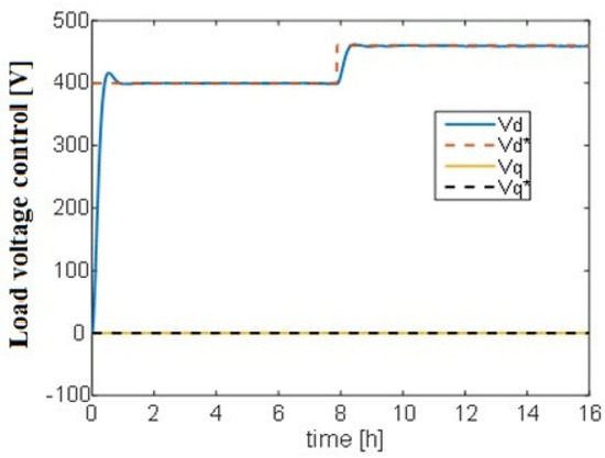
Figure 15.
Load voltage control results using an NPC inverter.
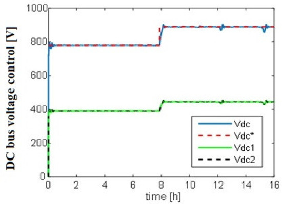
Figure 16.
Vdc voltage and DC bus capacitors voltages balance control results.
Battery power control result is presented in Figure 17. To show the performances of the battery power control, a close-up of Figure 17 is given in Figure 18. One can clearly note that the battery controller acts efficiently, where the battery power follows the power reference (). Thus, the charge and discharge of battery cells function in optimal operation conditions. To avoid battery deterioration, the battery controller keeps the limitation of voltage at a lower setting than the maximum value but more than the minimum value. The battery cell voltage is unpredictable and depends on the components of high frequency for the load current.
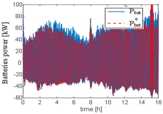
Figure 17.
Result of battery power control.
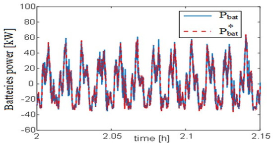
Figure 18.
Close-up of Figure 17.
The speed control performance of the diesel engine is shown in Figure 19. This performance changes inversely with the diesel power contribution in the link of the DC bus, i.e., if the power request decreases, the speed rises. The speed control shows its effective behavior by following the estimate speed () from the mechanical torque to speed reference (). The sum of low frequency components for the load current guides the DG generation to compensate shortage of power delivered from other renewable energies. The control method shows its ability to adapt the dynamic response and reduce load current fluctuations.
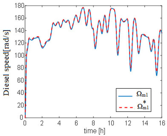
Figure 19.
Result of diesel engine speed control.
The control results of the wind turbine torque are shown in Figure 20. This control carried out through the current loop shows a good correlation between the wind generator current and its reference. The wind turbine MPPT sharply extracts the MPP from the permanent magnet generator PMG using the three-level rectifier associated with a three-level doubly boost converter connected to the DC bus. Under varying wind conditions, the proposed method demonstrated the stability of the recursive MPPT.
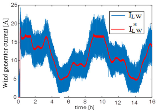
Figure 20.
Control of the current wind generator, where I*Lw = ILwref.
7. Discussion
The Matlab/Simulink software simulated the performance of the sources, converters, and load of the micro-grid system. In addition, the control system of each component and the strategy of the management of sharing power has been presented. The diesel generator, wind turbine, PV arrays, and backup batteries were set according to the data in Table 1. The three-level converter is linked between the power source (PV), wind power source, diesel system, variable load, and the 800 V DC bus.
Different generation conditions have been considered for the schematic management, including for emergency cases, as in Figure 10. The power profile of the wind turbine, PV, and load variation was created based on real data collected from a site in France. The results show that power fluctuations from resources and load have been efficiently compensated based on the proposed management strategy. The charging status of stored batteries performed well, according to optimal operation conditions and depending on its negative zones or positive zones.
One can clearly note that the proposed controllers efficiently responded and maintained the DC bus voltage within the limitations required. The power reference for each controller followed the power components of high or low frequency for power flow well. The results shown in Figure 16, Figure 17, Figure 18, Figure 19 and Figure 20 are the performance of the proposed controllers for converters and the inverter, such as the speed control of a diesel engine, the control of wind turbine torque, the MPPT for the PV system, and the three-level inverter for the load.
8. Conclusions
This paper presents a micro-grid based on a generator type variable speed diesel associated with PV, wind turbine, and storage batteries. This system is intended to feed home appliances in an isolated area. Energy management was carried out in the sense of optimizing energy production within the system by maximizing the share of renewable energies and minimizing the contribution of the variable speed diesel generator, since the power produced by DG is polluting and the cost of producing thermal energy is high due to the supply of diesel in isolated areas. In addition, the intermittency of renewable energies causes them to be unreliable and the coupling of the various types of production units thus proves to be a good way to compensate the weaknesses of each of the sources. A pack of batteries is connected to the link of DC bus through the DC/DC (three-level) converter to compensate the high frequency fluctuations of power from the renewable sources of energy. The simulation has evaluated the performances of the proposed micro-grid to demonstrate the feasibility of the micro-grid.
9. Future Work
The proposed control system was implemented in the environments of Simulink blocks, and the results satisfied the main objectives of this research. The real data were collected from a site in Le Havre, France, to test the proposed system. The design of this system based on the available equipment at the center of research at the University of Le Havre, Le Havre, France. The team of researchers are intending to experimentally test the proposed control strategy to manage power production at GREAH laboratory. The experimental and simulations results will be compared in order to demonstrate the efficiency of the proposed control strategy.
Author Contributions
Conceptualization, M.G.L. and M.B.C.; methodology, M.B.C.; software, M.G.L.; validation, M.G.L., M.B.C. and B.D.; formal analysis, M.G.L., M.B.C. and B.D.; investigation, M.B.C.; data curation, M.G.L.; writing—original draft preparation, M.G.L.; writing—review and editing, A.A.A., A.S.S. and M.B.C.; supervision, M.B.C. and B.D.; project administration, B.D.; funding acquisition, M.B.C. All authors have read and agreed to the published version of the manuscript.
Funding
This work was supported by the University of Le Havre Normandie and the Normandy region in France.
Data Availability Statement
Not applicable.
Acknowledgments
This work was supported by the university of Le Havre Normandy and is funded by the Normandy region in France. The project handles energy concerning CO2 emissions and adopting technologies of low pollution, such as wind turbines, PV panels, batteries, and energy management system.
Conflicts of Interest
The authors declare no conflict of interest.
Nomenclature
| PV | Photovoltaic panels |
| DG | Diesel generator |
| Vbat | Batteries voltage in [V] |
| Ibat and Ibat* | The current of battery and its reference in [A] |
| Pbat* | Battery’s power reference in [W] |
| Vpv | Voltage of the PV in [V] |
| Ipv | Current of the PV in [A] |
| ILw | Wind turbine side AC/DC converter output current [A] |
| PMG | Permanent Magnet Generator |
| Rs1 | Resistance of PMG1 (0.2 Ω) |
| Ld1 | Lq1 Inductances of PMG1 (1.5 mH) |
| φm1 | Permanent Magnet flux of PMG1 (0.85Wb) |
| J1 | The moment of inertia of diesel-generator (0.9 kg/m2) |
| J2 | Inertia moment of the wind system (1.2 kg/m2) |
| Ωm1 | Diesel speed in [rad/s] |
| Ωm1* | Diesel speed reference in [rad/s] |
| p1 | PMG1 pair of poles (3) |
| Vdc and Vdc* | DC bus voltage and its reference in [V] |
| Iload | Load current in [A] |
| Vd and Vq | Voltages of the load based on axis (d and q) in [V] |
| C1, C2 | DC bus capacitors in [F] |
References
- International Energy Agency (IEA). Annual Report 2021, “Clean Energy Transitions Programme 2021”. 2021. Available online: https://www.iea.org/reports/renewable-electricity (accessed on 18 November 2022).
- Silva, L.M.R.; Beluco, A.; Daronco, G. A wind PV diesel hybrid system for energizing a sewage station in Santa Rosa, in southern Brazil. IEEE Lat. Am. Trans. 2020, 18, 773–780. [Google Scholar] [CrossRef]
- Mohanty, A.; Patra, S.; Ray, P.K. Robust fuzzy-sliding mode based UPFC controller for transient stability analysis in autonomous wind-diesel-PV hybrid system. IET Gener. Transm. Distrib. 2016, 10, 1248–1257. [Google Scholar] [CrossRef]
- Rinaldi, F.; Moghaddampoor, F.; Najafi, B.; Marchesi, R. Economic feasibility analysis and optimization of hybrid renewable energy systems for rural electrification in Peru. Clean Technol. Environ. Policy 2020, 23, 731–748. [Google Scholar] [CrossRef]
- Suresh, G.; Prasad, D.; Gopila, M. An Efficient Approach based Power Flow Management in Smart Grid System with Hybrid Renewable Energy Sources. Renew. Energy Focus 2021, 39, 110–122. [Google Scholar]
- Kant, K.; Jain, C.; Singh, B. A Hybrid Diesel-Wind-PV-Based Energy Generation System with Brushless Generators. IEEE Trans. Ind. Inform. 2017, 13, 1714–1722. [Google Scholar] [CrossRef]
- Tabak, A.; Kayabasi, E.; Guneser, M.T.; Ozkaymak, M. Grey wolf optimization for optimum sizing and controlling of a PV/WT/BM hybrid energy system considering TNPC, LPSP, and LCOE concepts. Energy Sources Part A Recovery Util. Environ. Eff. 2022, 44, 1508–1528. [Google Scholar] [CrossRef]
- Mandal, S.; Mandal, K.K. Optimal energy management of microgrids under environmental constraints using chaos enhanced differential evolution. Renew. Energy Focus 2020, 34, 129–141. [Google Scholar] [CrossRef]
- Sarker, K.; Chatterjee, D.; Goswami, S.K. Grid integration of photovoltaic and wind-based hybrid distributed generation system with low harmonic injection and power quality improvement using biogeography-based optimization. Renew. Energy Focus 2017, 2017, 2083–2087. [Google Scholar] [CrossRef]
- Sheng, S.; Zhang, J. Capacity configuration optimisation for stand-alone micro-grid based on an improved binary bat algorithm. J. Eng. 2017, 2017, 2083–2087. [Google Scholar] [CrossRef]
- Fathy, A.; Kaaniche, K.; Alanazi, T.M. Recent Approach Based Social Spider Optimizer for Optimal Sizing of Hybrid PV/Wind/Battery/Diesel Integrated Microgrid in Aljouf Region. IEEE Access 2020, 8, 57630–57645. [Google Scholar] [CrossRef]
- Rathore, A.; Patidar, N.P. Reliability constrained socio-economic analysis of renewable generation based standalone hybrid power system with storage for off-grid communities. IET Renew. Power Gener. 2020, 14, 2142–2153. [Google Scholar] [CrossRef]
- Kusakana, K. Optimal scheduled power flow for distributed photovoltaic/wind/diesel generators with battery storage system. IET Renew. Power Gener. 2015, 9, 916–924. [Google Scholar] [CrossRef]
- Rehman, S.; Natrajan, N.; Mohandes, M.; Alhems, L.M.; Himri, Y.; Allouhi, A. Feasibility Study of Hybrid Power Systems for Remote Dwellings in Tamil Nadu, India. IEEE Access 2020, 8, 143881–143890. [Google Scholar] [CrossRef]
- Rehman, S.; Habib, H.U.R.; Wang, S.; Buker, M.S.; Alhems, L.M.; Al Garni, H.Z. Optimal Design and Model Predictive Control of Standalone HRES: A Real Case Study for Residential Demand Side Management. IEEE Access 2020, 8, 29767–29814. [Google Scholar] [CrossRef]
- Yaramasu, V.; Wu, B.; Alepuz, S.; Kouro, S. Predictive control for low-voltage ride-through enhancement of three-level-boost and NPC-converter-based PMSG wind turbine. IEEE Trans. Ind. Electron. 2014, 61, 6832–6843. [Google Scholar] [CrossRef]
- Adhikari, J.; Prasanna, I.V.; Panda, S.K. Maximum power-point tracking of high altitude wind power generating system using optimal vector control technique. In Proceedings of the International Conference on Power Electronics and Drive Systems, Sydney, Australia, 17 August 2015; pp. 773–778. [Google Scholar]
- Mi, Y.; Ma, C.; Fu, Y.; Wang, C.; Wang, P.; Loh, P.C. The SVC additional adaptive voltage controller of isolated wind-diesel power system based on double sliding-mode optimal strategy. IEEE Trans. Sustain. Energy 2018, 9, 24–34. [Google Scholar] [CrossRef]
- Rezkallah, M.; Hamadi, A.; Chandra, A.; Singh, B. Design and Implementation of Active Power Control with Improved P&O Method for Wind-PV-Battery-Based Standalone Generation System. IEEE Trans. Ind. Electron. 2018, 65, 5590–5600. [Google Scholar] [CrossRef]
- Chen, H.C.; Lin, W.J. MPPT and voltage balancing control with sensing only inductor current for photovoltaic-fed, three-level, boost-type converters. IEEE Trans. Power Electron. 2014, 29, 29–35. [Google Scholar] [CrossRef]
- Teymour, H.R.; Sutanto, D.; Muttaqi, K.M.; Ciufo, P. Solar PV and battery storage integration using a new configuration of a three-level NPC inverter with advanced control strategy. IEEE Trans. Energy Convers. 2014, 29, 354–365. [Google Scholar] [CrossRef]
- Nathenas, T.; Adamidis, G. A new approach for SVPWM of a three-level inverter-induction motor fed-neutral point balancing algorithm. Simul. Model. Pract. Theory 2012, 29, 1–17. [Google Scholar] [CrossRef]
- Tani, A.; Camara, M.B.; Dakyo, B. Energy Management in the Decentralized Generation Systems Based on Renewable Energy—Ultracapacitors and Battery to Compensate the Wind/Load Power Fluctuations. IEEE Trans. Ind. Appl. 2015, 51, 1817–1827. [Google Scholar] [CrossRef]
- Wang, C.; Mi, Y.; Fu, Y.; Wang, P. Frequency control of an isolated micro-grid using double sliding mode controllers and disturbance observer. IEEE Trans. Smart Grid 2018, 9, 923–930. [Google Scholar] [CrossRef]
- Motapon, S.N.; Dessaint, L.A.; Al-Haddad, K. A comparative study of energy management schemes for a fuel-cell hybrid emergency power system of more-electric aircraft. IEEE Trans. Ind. Electron. 2014, 61, 1320–1334. [Google Scholar] [CrossRef]
- Bellache, K.; Camara, M.B.; Dakyo, B. Transient power control for diesel-generator assistance in electric boat applications using supercapacitors and batteries. IEEE J. Emerg. Sel. Top. Power Electron. 2018, 6, 416–428. [Google Scholar] [CrossRef]
- Camara, M.S.; Camara, M.B.; Dakyo, B.; Gualous, H. Permanent Magnet Synchronous Generator for Offshore Wind Energy System Connected to Grid and Battery-Modeling and Control Strategies. Int. J. Renew. Energy Res. 2015, 5, 386–393. [Google Scholar]
Publisher’s Note: MDPI stays neutral with regard to jurisdictional claims in published maps and institutional affiliations. |
© 2022 by the authors. Licensee MDPI, Basel, Switzerland. This article is an open access article distributed under the terms and conditions of the Creative Commons Attribution (CC BY) license (https://creativecommons.org/licenses/by/4.0/).