1. Introduction
Various waste-to-energy (WTE) conversion technologies can generate energy, more sustainable production, and useful co-products.
The energy efficiency was improved with the combination of heat and mechanical power. Kalitventzeff and co-authors [
1] described this application within an ammonia production plant, revisiting the major rules of energy integration from the perspective of overall energy efficiency, including the combined production of heat and mechanical power for an existing process.
The co-product, CO
2, was used as an energy source in different industries. Sabtini et al. [
2] investigated closed CO
2 cycles for existing nuclear power stations, and their study showed that s-CO
2 was suitable for this application. Pham et al. [
3] analysed the performance of s-CO
2 used in the application of small modular reactors and showed that the thermal efficiency of s-CO
2 could be increased by modifying the cycle configurations. Kim et al. [
4] compared s-CO
2 with different configurations, which were applied as the bottoming cycle of a landfill gas-fired gas turbine. Amini and others [
5] focused on waste heat recovery for exhaust gases (at 150 °C) from combined cycle power plants. Their results indicated that the t-CO
2 could produce more power and enhance the total efficiency of the power plant.
Liquefied natural gas was utilised in plants. Shi et al. [
6] proposed a system in which a liquefied natural gas cold stream was used for in-house compressor inlet air cooling and reported an overall enhancement of 3% in electricity production. Wang and others [
7] followed a formal mathematical programming approach to identify performance improvement opportunities in a liquefied natural gas plant.
The waste was used as raw material in different plants. Zhao et al. [
8] studied the gasification of a local municipal solid waste (MSW) mixture. Chen and others [
9] proposed the use of zeotropic mixtures with refrigerants as working fluids in the organic Rankine cycle process for waste heat recovery. Lee et al. [
10] studied compressed natural gas and ethanol production from MSW. Pyrolysis processes convert waste into bio-char, bio-oil, and gases [
11], and this bio-oil can be hydro-processed further to produce gasoline and diesel blend stocks [
12]. Cucchiella et al. [
13] presented a strategy analysis of the amount of waste required to incinerate with energy recovery, considering different approaches based on unsorted waste, landfill waste, and separated collection rate, respectively. Beyene et al. [
14] reviewed the recent and emerging waste-to-energy (WtE) technologies, which advance toward using MSW to produce renewable energy.
Biomass waste was used for bioenergy and biofuels using pyrolysis technology. Li and co-researchers [
15] investigated a strategy for adjusting the nutrient composition of the feeding wastewater for microalgae cultivation and biofuel production. Huang et al. [
16] presented a new workflow of biofuel generation from microalgae biomass through lipid extraction and pyrolysis of defatted microalgae residues.
The heat integration and use of multiple feeds recovered the energy for various industries. Fujii and co-workers [
17] presented a combined system that used biogas to heat steam recovered from an incineration boiler with separate superheating equipment. Hwang [
18] analysed the performance of an integrated vapour compression refrigeration system with a micro-turbine and vapour absorption chiller driven by waste heat from the microturbine. Gogoi and Talukdar [
19] performed a detailed thermodynamic analysis of a combined reheat regenerative steam based on the power cycle and H
2O-LiBr vapour absorption refrigeration system from a first law point of view, and also an exergy-based parametric analysis of the same system. Ge et al. [
20] evaluated the performance, with simulation and experiment, of a gas turbine power plant integrated with an absorption system for a supermarket. Soltanieh et al. [
21] studied the implementation of large-scale polygeneration plants which use multiple feeds (such as coal and natural gas), and produce multiple products (such as power, liquid fuels, and chemicals).
The modification and upgrade of turbines improved the working of the turbines. Musacchio and co-workers [
22] presented the single components of the gas turbine, decarbonising material sourcing and machining in the gas turbine sector through a cost-carbon footprint nexus analysis. Liu et al. [
23] studied the performance comparisons of three configurations of an aviation fuel cell gas turbine hybrid power generation system. Cha and researchers [
24] designed a gas turbine–carbon dioxide combined cycle power plant (GT-CO
2 CCPP) with a gas turbine inlet air cooling and heat recovering system when using liquefied natural gas cold energy.
Concentrated solar power (CSP) can be converted into electricity by using solar energy and calcium looping [
25]. Thermal energy storage (TES), phase change materials (PCM), and thermochemical energy storage (TCES) systems constitute the most interesting and applicable energy storage technologies for CSP [
26,
27]. One of the most promising chemical systems for TCES in large-scale production is the CaO/CaCO
3 performing the calcium looping (CaL) process [
28,
29], including different sorbents for direct air capture of carbon dioxide (CO
2), which takes place in the calcination–carbonation reaction [
30,
31].
This paper presents electricity generation using one and/or two open gas turbines by using the upgraded electricity cogeneration technique.
2. Upgraded Electricity Cogeneration Technique
The upgraded electricity cogeneration technique can exploit the energy from a working fluid by using an open gas turbine. A conventional gas turbine is a rotary engine that extracts energy from the flow of combustion gas. Gas turbines operate on the principle that fuel and air will burn in a combustion chamber. The outlet gas serves as a working fluid. The combustible products are then expanded within one turbine, which drives an electric generator [
32]. This research aims to upgrade unsustainable methanol production into a sustainable process using wastes and two open gas turbines, one turbine during the high-pressure product reaction loop and the second turbine during the exhaust gas phase for co-product production, including one combined compressor. This research project considers an upgraded electricity cogeneration technique, which is carried out in two steps, using otherwise useless polyethylene waste, flue gas, and wood for electricity cogeneration.
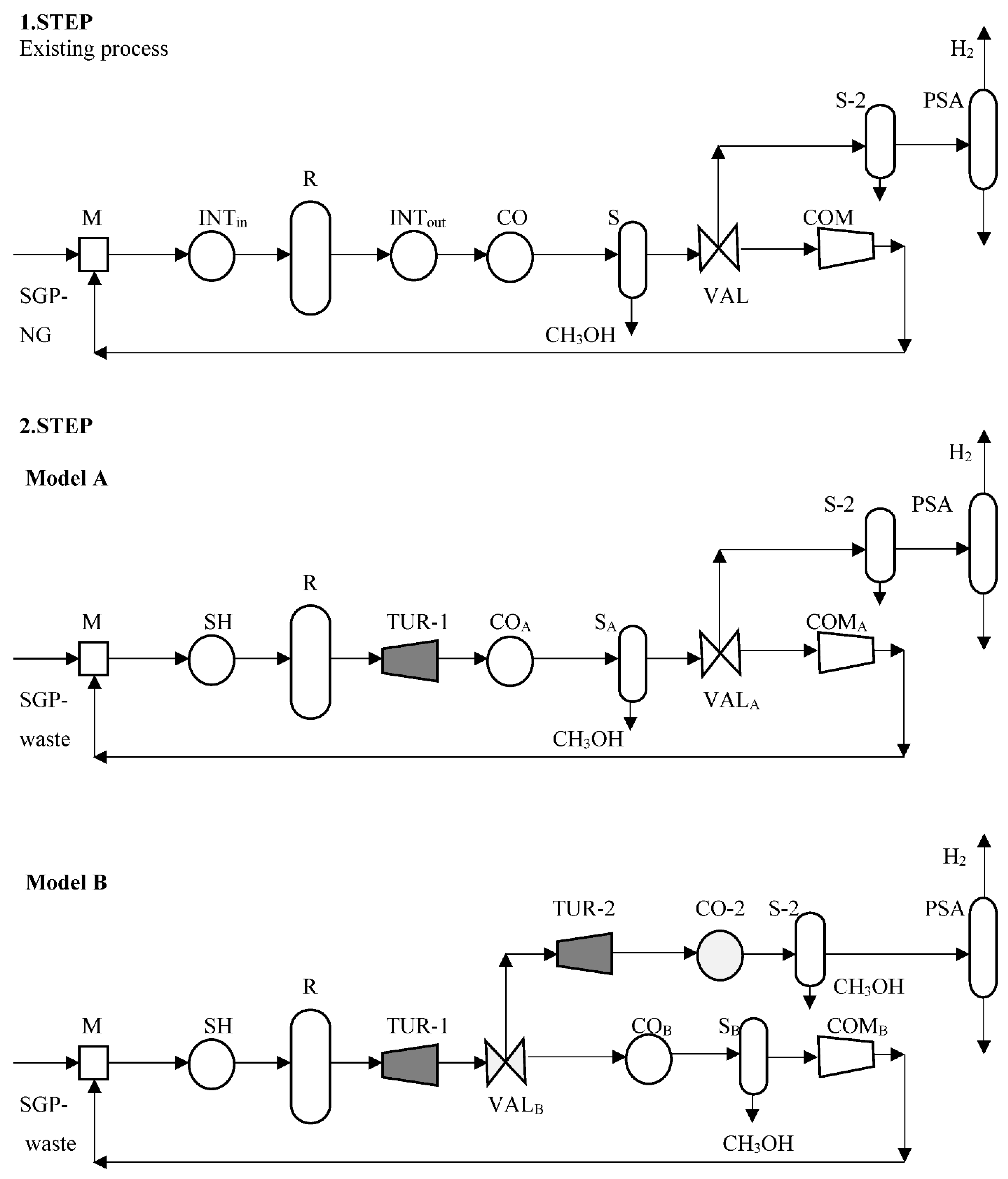
In the first step, we simulate the simulation model of the existing energy-intensive product production with a well-known technology, and process units using the Aspen Plus
® simulator (
Figure 1). Most high-pressure exothermic chemical processes are operated within a circular system, including a preheater using the integration between the reactor’s outlet and inlet streams (INT, with the heat flow rate;
ϕINT), the exothermic reactor (R; with
ϕR), where the product and steam are produced, a heat-exchanger for forward cooling the reactor’s outlets (CO; with
ϕCO), separators (S and S-2) for product and unreacted gas separation, an exhaust gas valve (VAL) using part of the unreacted gas for the co-product (PSA) and a compressor (COM; with
ϕCOM) for raising the pressure of the circulated unreacted gas. The streams are mixed into a mixer (M) after compressing the COM and flowing from the syngas production (SGP). The maximum available electricity cogeneration can previously be determined from the thermodynamics of the products and co-products, and an existing energy unit’s characteristic capacity of
ϕINT,
ϕR,
ϕCO, and
ϕCOM (
Figure 1).
In the second step, the conventional natural gas is replaced with waste as the raw materials by using the same simulated model from the first step, including electricity cogeneration with a gas turbine during the high-pressure product reaction loop (Model A), and using the exhaust gas for the co-product (Model B), combining them with only one compressor (
Figure 1).
Model A includes one open gas turbine after the reactor with steam production going into the reactor. The working fluid for the gas turbine (TUR-1) uses the reactor’s outlet with a pressure drop and allows the temperature to drop. The available heat is used to produce electricity within a generator. The integration heat exchanger (INT) after the turbine installation cannot be integrated between the reactor’s outlet and inlet and is replaced with steam heating (SH). The other process units are not changed. They can be followed by the cooling of the gas turbine outlet (CO
A), product separation (S
A), exhausting (VEN
A), and compressing (COM
A;
Figure 1).
Model B includes one open gas turbine after the reactor (TUR-1, and it is the same as in Model A). The exhaust gas valve (VAL
B) is installed after the gas turbine outlet. One part of the unreacted gas is circulated, and the exhaust gas enters into the second gas turbine (TUR-2;
Figure 1) followed by the cooling outlet (CO-2), product separation (S-2), and co-product separation using pressure swing adsorption (PSA). The circulated unreacted gas is cooled by using a heat exchanger (CO
B), followed by separating (S
B) and compressing (COM
B).
The maximum available electricity cogeneration (
Pel-TUR; Equations (1) and (2)) was previously determined from the product thermodynamic using the heat capacity of the outlet flow rate (
FCpTUR), the number of components going into the outlet (
FCpTUR,com; com = 1…Com), and the temperature difference between the inlet (
TTUR,in) and outlet (
TTUR,out) gas turbines (Δ
TTUR). The turbine’s power (
PTUR; with
ηtur) and heat flow rate (
ϕTUR; with
ηtur) is calculated by using Equation (2). The total thermodynamic and mechanical efficiency of both medium-pressure turbines (
ηtur) is 70%, and the same for electricity cogeneration (
ηel).
The electricity cogeneration income (
Inel-TUR in MEUR/a) using a turbine with a known price (
Cel = 0.45 MEUR/(MW·a) is:
The annual depreciation of a medium-pressure turbine (
CdTUR in MEUR/a) is a function of the power (
PTUR in MW):
3. Case Study of the Upgraded Electricity Cogeneration Technique
The upgraded electricity cogeneration technique was tested on the existing crude methanol process, replacing unsustainable natural gas with otherwise useless polyethylene waste and flue gas by using two steps. The same case study was then repeated using only wood.
The first step was simulated using the simulation model from the existing energy-intensive crude methanol using the Aspen Plus
® simulator (
Figure 2). The simulated model was adapted well to the existing process. The natural gas (almost 100% methane;
FCH4 = 1240 kmol/h) for syngas production (SGP;
Figure 2) was first desulphurised and then heated within a steam reformer (ref; using an Rgibbs reactor from Aspen Plus
®), where syngas was produced from the natural gas and steam (
FH2O = 2000 kmol/h) on an NiO catalyst at 855 °C and 15 bar:
The hot stream of syngas (
FCO2 = 223 kmol/h,
FCO = 668 kmol/h,
FCH4 = 348 kmol/h,
FH2= 2897 kmol/h
, FH2O = 885 kmol/h) was cooled within many heat exchangers to 40 °C, water condensed, and compressed to 50 bar (SGP;
Figure 2). The syngas and circulated stream were mixed at the reactor’s inlet within a mixer M (
Figure 2). The reactor’s inlet was heated to 225 °C within a preheater using the integration between the reactor’s outlets (INT;
ϕINT = 10.7 MW). Methanol was produced by the catalytic hydrogenation of carbon monoxide and/or carbon dioxide within an exothermic reactor (R; using a Requil reactor from Aspen Plus
®;
ϕR = 14 MW), using two main reactions:
The reactor’s outlet was cooled within the heat exchanger INT to 123 °C and within the heat exchanger system (CO;
ϕCO = 7 MW, includes three heat exchangers) to 40 °C, where boiling water was prepared. The separator (S) for the product and unreacted gas separation was separated into 540 kmol/h crude methanol (
FCH3OH,ex) at 40 °C and 40 bar. The exhaust gas valve (VAL) was used to exhaust half of the unreacted gas, which was separated into 1750 kmol/h hydrogen (
FH2,ex) using a PSA column. The compressor (COM;
ϕCOM = 0.57 MW) raised the pressure of the circulated unreacted gas to 50 bar (
Figure 2). Crude methanol was cleaned within the distillation columns (this part of the process is not included in this research). The existing energy units’ characteristic capacity represents the heat flow into the units of INT and COM (
ϕINT = 10.7 MW,
ϕCOM = 0.57 MW).
In the second step, conventional natural gas could be replaced with waste as raw materials by using the same simulated model from the first step. The natural gas was replaced with waste, such as otherwise useless polyethylene waste (PEW), which was separated from municipal solid waste (MSW), gasified, and reformed ([
33]; reaction Re5;
FC2H4,in = 1000 kmol/h;
FH2O,in,Re5 = 2000 kmol/h), and purified flue gas (without particles, NO
x, SO
x, and nitrogen;
FCO2,in = 240 kmol/h;
FH2O,in = 920 kmol/h). Nitrogen (
FN2,in = 2800 kmol/h) from flue gas was separated for ammonia production.
The crude methanol production from waste was 30% higher than within the existing process because more CO was synthesised within the Re5 reaction. The steam production within the reactor was 30% higher because of a greater released heat flow rate within the Re3 reaction (
ϕR = 19 MW). The simulated model for crude methanol production from waste was modified for electricity cogeneration based on Model A, with one open gas turbine after the reactor (TUR-1;
Figure 2). The maximally allowed pressure drop was 20 bar during the reactor’s loop. The working fluid for the gas turbine underwent pressure (from 50 to 30 bar) and temperature (from 250 to 170 °C) drops with a power of 3.6 MW (
PTUR-1). The reactor’s inlet was not heated using INT integration, as this was replaced with an SH heat exchanger (
ϕSH = 10.4 MW), for which 50% additional steam had to be bought, and the rest could be produced within the reactor. The other process units were not changed, and so what followed was the cooling of the gas turbine outlet (CO
A;
ϕCO,A = 14 MW) to 40 °C, crude methanol separating (S
A) of 710 kmol/h (
FCH3OH,A), exhausting (VEN
A) with 30% higher outlet and compressing to 50 bar (COM;
ϕCOM,A = 0.43 MW;
Figure 2). The exhaust outlet should be exhausted with an extra 30% flow rate, due to the circulated flow rate being too high during the reactor’s loop. The hydrogen was only separated for 1560 kmol/h (
FH2,A) by using the PSA. This was 11% lower than within the existing process because the hydrogen was more reacted within the Re3 reaction for generating methanol. The comparison between the existing energy units’ characteristic capacity (
ϕINT = 10.7 MW,
ϕCOM = 0.57 MW) and that after the change in raw material for Model A (
ϕSH = 10.4 MW,
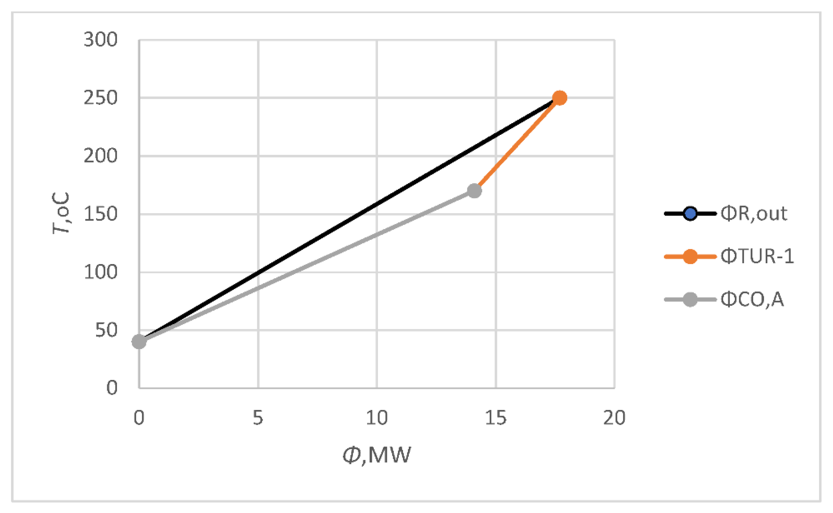
ϕCOM,A = 0.43 MW), confirmed that the usage of the existing units was a good idea. The available reactor’s outlet heat flow rate (
ϕR,out) was 17.6 MW in Model A, which was used for electricity cogeneration within the gas turbine (
ϕTUR-1 = 3.6 MW) and cooling within the CO
A cooler system (where boiler water was prepared;
ϕCO,A = 14 MW;
Figure 3). The electricity cogeneration within the gas turbine (
ϕTUR-1) was presented 20% of the available energy (
ϕR,out;
Figure 3).
Model B included one open gas turbine after the reactor (TUR-1) and a second one during the exhaust gas process (TUR-2,
Figure 2). The exhaust gas valve (VAL
B) could be installed after the first gas turbine, which should be exhausted with a 30% greater flow rate (for the same reason as with Model A). During the exhaust gas, there is a second gas turbine (
PTUR2 = 2 MW) with pressure and temperature drops of 10 bar (from 30 to 20 bar) and 52 °C (from 170 to the lowest allowed temperature of 118 °C). The outlet gas after the second turbine was cooled within the CO-2 heat exchanger system (
ϕCO-2 = 9 MW) to 40 °C. One part of the crude methanol was separated with a separator (S-2) at a rate of 550 kmol/h. The hydrogen was cleaned at a rate of 1560 kmol/h (
FH2,B) using the PSA column. The circulated unreacted gas as the second outlet from VAl
B was cooled by using a CO
B heat exchanger (
ϕCO,B = 2.8 MW), then separating the (S
B) methanol at 145 kmol/h and compressing it (COM
B,
ϕCOM,B = 0.4 MW) from 30 to 50 bar. The total crude methanol production was 695 kmol/h (
FCH3OH,B). Heating within the SH and additional steam production within the reactor were the same as with Model A. The comparison between the existing energy units’ characteristic capacity (
ϕINT = 10.7 MW,
ϕCOM = 0.57 MW) and after the change in raw material for Model B (
ϕSH = 10.4 MW,
ϕCOM,B = 0.4 MW) confirmed that the usage of the existing units is a good idea. The available reactor’s outlet heat flow rate (
ϕR,out) was 17.6 MW in Model B (the same as with Model A), which was used for electricity cogeneration within two gas turbines (
ϕTUR-1,
ϕTUR-2), and cooling within the CO
B and CO-2 heat exchangers (
ϕCO,B= 2.8 MW and
ϕCO-2= 9 MW, where boiling water was prepared;
Figure 4). The electricity cogenerations within the gas turbines TUR-1 (
ϕTUR-1) and TUR-2 (
ϕTUR-2) were presented at 20% and 11% of the available energy (
ϕR,out;
Figure 4).
The maximum available electricity cogeneration within the first turbine (
Pel-TUR-1; using Equations (1) and (2)) could be determined previously from the product’s thermodynamic using the heat capacity of the outlet flow rate (
FCpTUR = 0.045 MW/K) and the number of components going into the outlet (
FCpTUR,com; com= CO, CO
2, H
2, CH
4, CH
3OH;
FCpTUR,CO = 0.005,
FCpTUR,CO2 = 0.007,
FCpTUR,H2 = 0.016,
FCpTUR,CH3OH = 0.012,
FCpTUR,CH4 = 0.005 MW/K), and the temperature difference (Δ
TTUR-1) between the inlet (
TTUR,in = 250 °C) and outlet (
TTUR,out= 170 °C) gas turbines (Equations (5)–(7)).
The maximum available electricity cogeneration within the second turbine (
Pel-TUR-2; Equation (8)) could be determined previously from the product`s thermodynamic using the heat capacity of the outlet flow rate (
FCpTUR = 0.045 MW/K) with the molar flow ratio of the exhaust gas (
r = 0.85; split with VEN
B) and the temperature difference between the inlet (
TTUR,in = 170 °C) and outlet (
TTUR,in = 118 °C) during the gas turbines (Equation (9)).
The same case was simulated for Models A and B (
Figure 2) using only waste wood, and the results were identical to those presented above, but two times more volume was needed for the wood because of the 50% lower carbon content.
Model A was operated with the additional methanol production of 170 kmol/h and the available electricity cogeneration of 2.52 MW, generating an additional profit of 7.18 MEUR/a using polyethylene waste and flue gas (Equation (14),
Section 3.1). The profit of Model A was 6.78 MEUR/a when using waste wood (Equation (15)).
Model B was operated with the additional methanol production of 155 kmol/h and the available electricity cogeneration of 3.92 MW, generating an additional profit of 7.28 MEUR/a using polyethylene waste and flue gas (Equation (17),
Section 3.1). The profit of Model B was 6.88 MEUR/a when using waste wood Equation (18).
The comparisons between Models A and B for the crude methanol production from polyethylene waste and flue gas were presented in
Table 1. Model B was operated with 55% higher electricity cogeneration, 9% lower methanol production, and 1.4% higher profit.
The selection of a sustainable raw material between polyethylene waste and flue gas or wood was dependent on the waste landfill’s availability. The price did not play a very important role, because the reprocessing cost was very similar for both. Model B was more profitable but needed more parts of the system to be replaced, while Model A was less profitable, but easier with regard to the technical installation.
3.1. Economic Analyses of the Case Studies
The economic analyses considered all changes to the existing process and additional modifications, including incomes and costs.
The raw material saving (
Sraw,
PP; Equation (10)) included the replacing of existing non-renewable sources (natural gas—NG,
CNG = 3 EUR/kmol;
FNG = 1240 kmol/h) with polyethylene waste (PEW,
FPEW = 1000 kmol/h, applied costs with separating, treating and production of gasified polyethylene waste
CPEW = 2.7 EUR/kmol) and purified flue gas without nitrogen (FG,
FFG = 240 kmol/h, applied cost
CFG = 2 EUR/kmol), for 8000 operation hours (
O) per year.
The raw material saving (
Sraw,
WO; Equation (11)) included the replacing of existing non-renewable sources (natural gas—NG,
CNG = 3 EUR/kmol;
FNG = 1240 kmol/h) with waste wood (WO,
FWO = 1240 kmol/h, applied costs with separating, treating and production of gasified waste
CWO = 2.6 EUR/kmol) for 8000 operation hours (
O) per year. For 1240 kmol/h two times more wood was needed than polyethylene waste and flue gas (
mPP = 40,000 kg/h).
The change in raw material generated a lower hydrogen separation of 190 kmol/h, with the additional charge (
CaH2) of 1.52 MEUR/a (
CH2 = 1 EUR/kmol; Equation (12)).
The economic analyses of the turbines included annual depreciation. The income of electricity cogeneration within the first and second turbines (Inel; using Equation (3)) were 1.134 and 0.63 MEUR/a.
The annual depreciations of the first and second medium-pressure turbines (CdTUR; using Equation (4)) were 0.234 and 0.13 MEUR/a.
Model A included the income (
InCH3OH,A) of additional methanol production of 170 kmol/h (
CCH3OH = 3 EUR/kmol; Equation (13)) generating 4.0 MEUR/a.
Model A also included the installation of one gas turbine (
CaTUR-1 = 0.1 MEUR/a) and the heating of steam within the SH heat exchanger (
CaSH = 0.4 MEUR/a). The profit of Model A (
ProfA,PP) was 7.18 MEUR/a, including natural gas being replaced with polyethylene waste and flue gas (Equation (14)):
The profit of Model A (
ProfA,WO) was 6.78 MEUR/a, including natural gas being replaced with waste wood (Equation (15)):
The profit of Model B included the income (
InCH3OH,B) from additional methanol production of 155 kmol/h (
CCH3OH = 3 EUR/kmol; Equation (16)) generating 3.72 MEUR/a (Equation (16)).
Model B included the installation of two gas turbines (CaTUR-1 and CaTUR-1), heating of steam within the SH heat exchanger (CaSH = 0.4 MEUR/a), replacing of the valve (CaVAL = 0.01 MEUR/a), and one of the heat exchangers from the CO system (CaCO = 0.01 MEUR/a).
The profit of Model B (
ProfB,PP) was 7.28 MEUR/a, including natural gas being replaced with polyethylene waste and flue gas (Equation (17)):
The profit of Model B (
ProfB,WO) was 6.88 MEUR/a, including natural gas being replaced with waste wood (Equation (18)):


