
Experimental Study on the Effect of Hydraulic Deterioration of Different Drainage Systems on Lining Water Pressure

Abstract
:1. Introduction
2. Drainage and Waterproof System
2.1. Traditional Waterproof and Drainage Systems in China
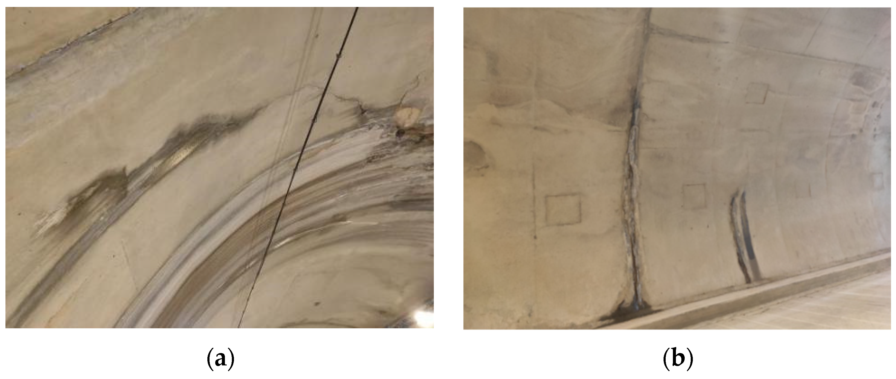
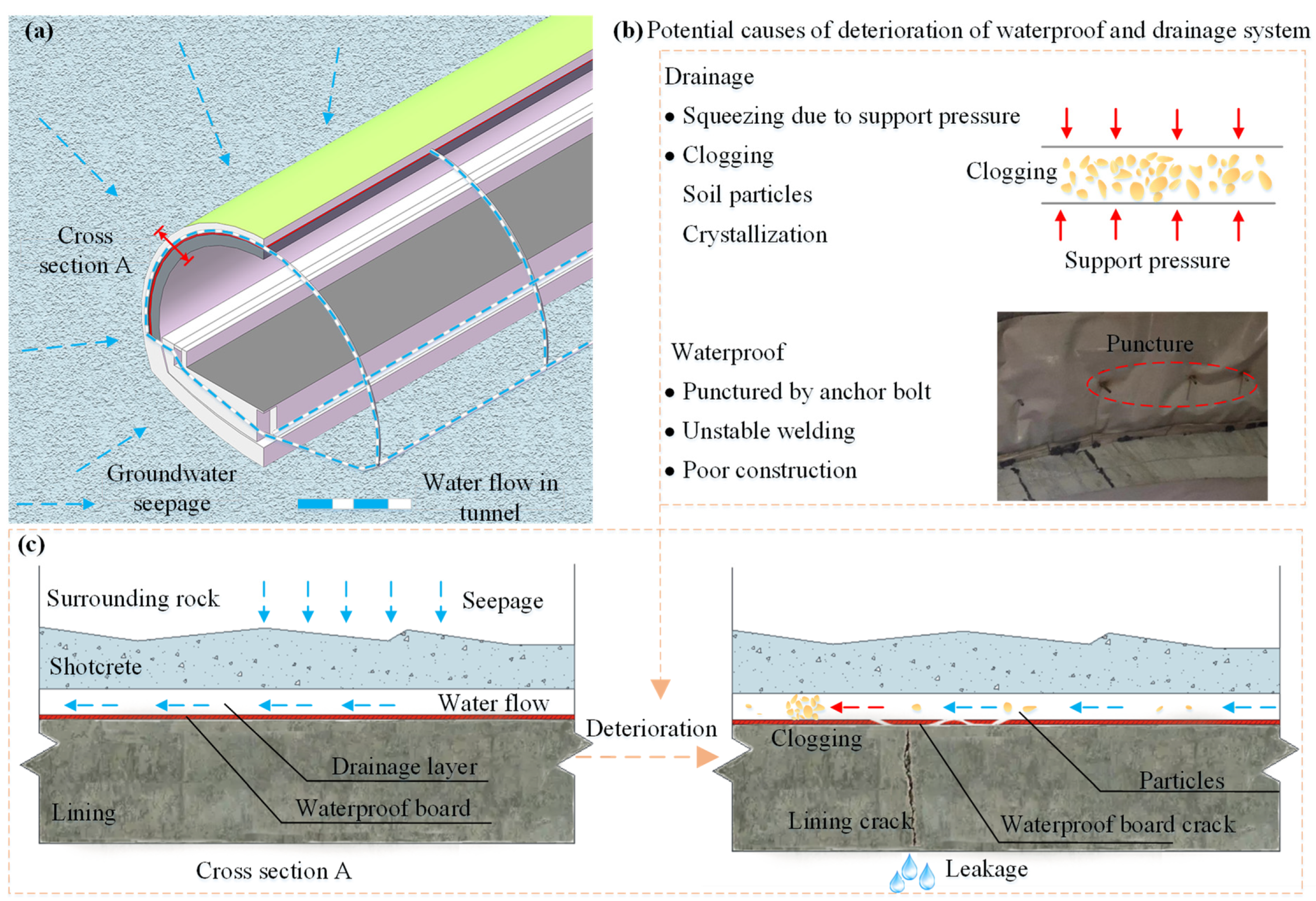
2.2. Deterioration of Traditional Waterproof and Drainage System
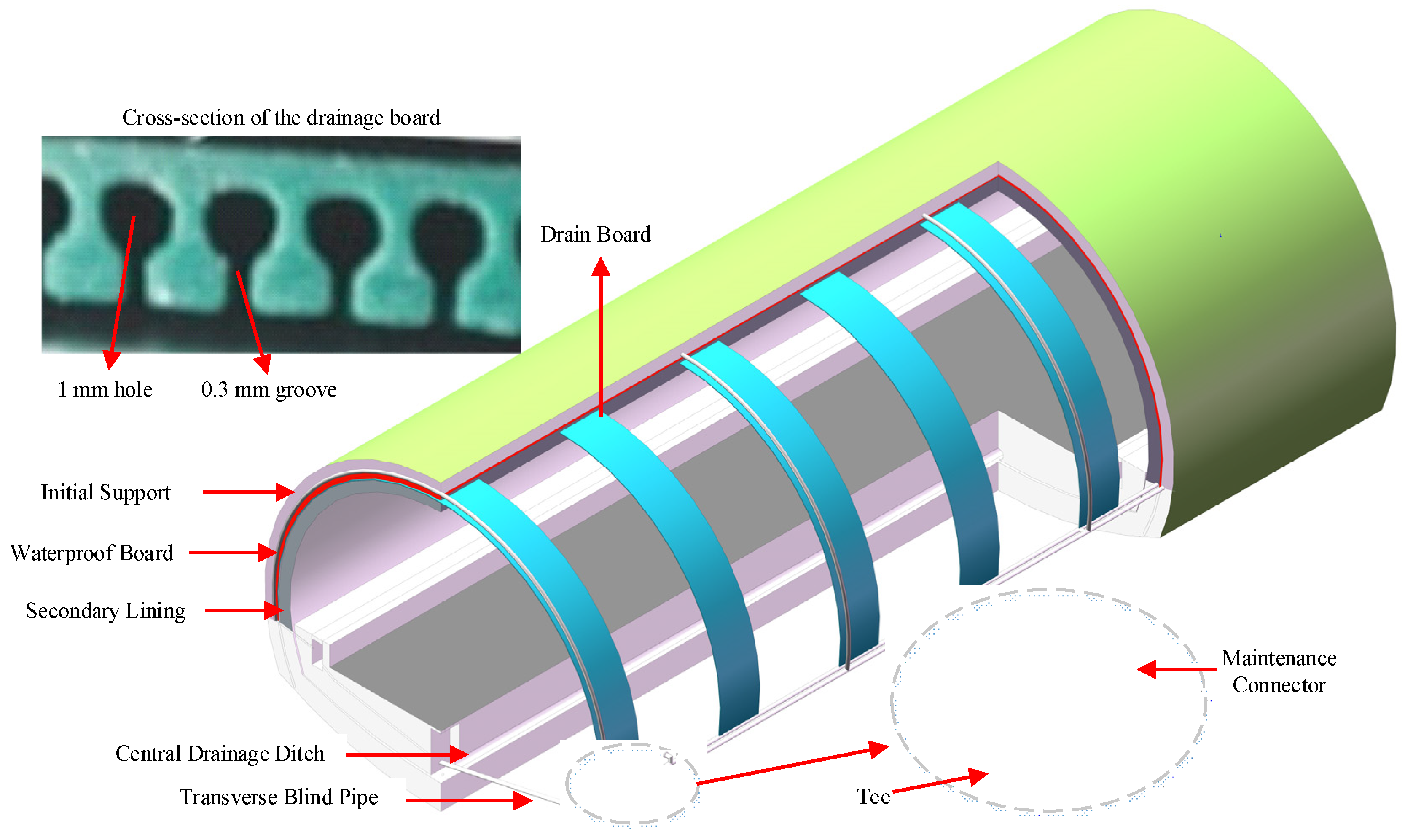
2.3. Design of Composite Waterproof and Drainage System
- 1.
- Traditional tunnel drainage blind pipes are prone to clogging. The capillary drainage board used behind the lining has an excellent anti-clogging ability to ensure the smoothness of the drainage system.
- 2.
- When the traditional waterproof and drainage system leaks because there is no drainage channel between the waterproof board and the secondary lining, if the lining surface is grouted and blocked, the groundwater will cross-flow between the waterproof board and the secondary lining and seep from another weak link. The composite drainage system is different from the traditional waterproof and drainage system in that the water seepage point on the lining surface can be directly sealed by grouting when the tunnel leaks. Because there is a drainage channel behind the lining, the water seepage will enter the drainage system through the drainage channel. Due to the additional drainage path behind the lining, the water seepage will be discharged through the drainage channel, which will significantly reduce the difficulty and cost of the current tunnel leakage treatment.
3. Model Test Preparation
3.1. Similarity of Scaled Model Test
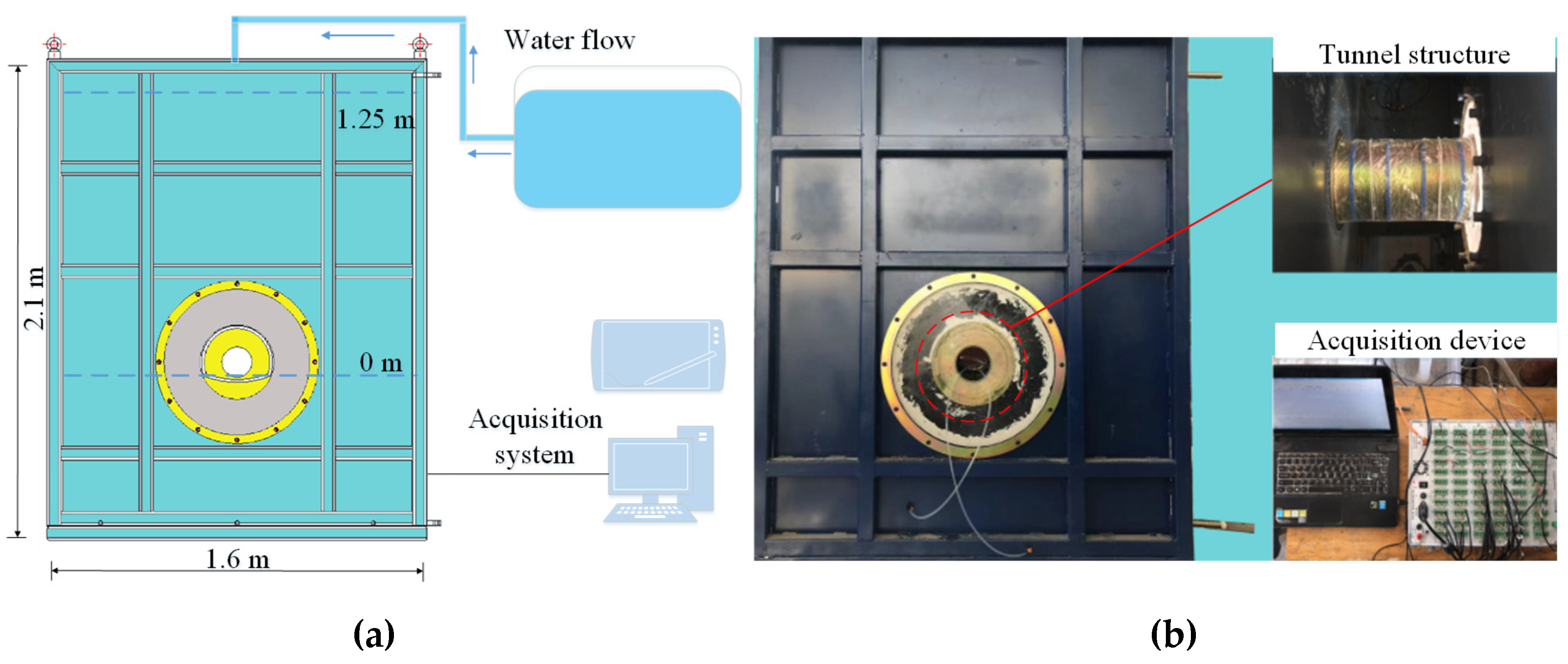
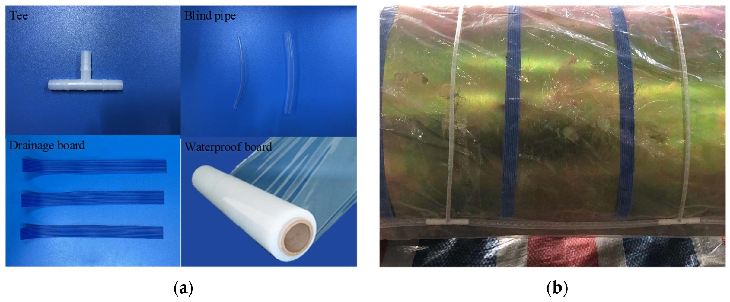
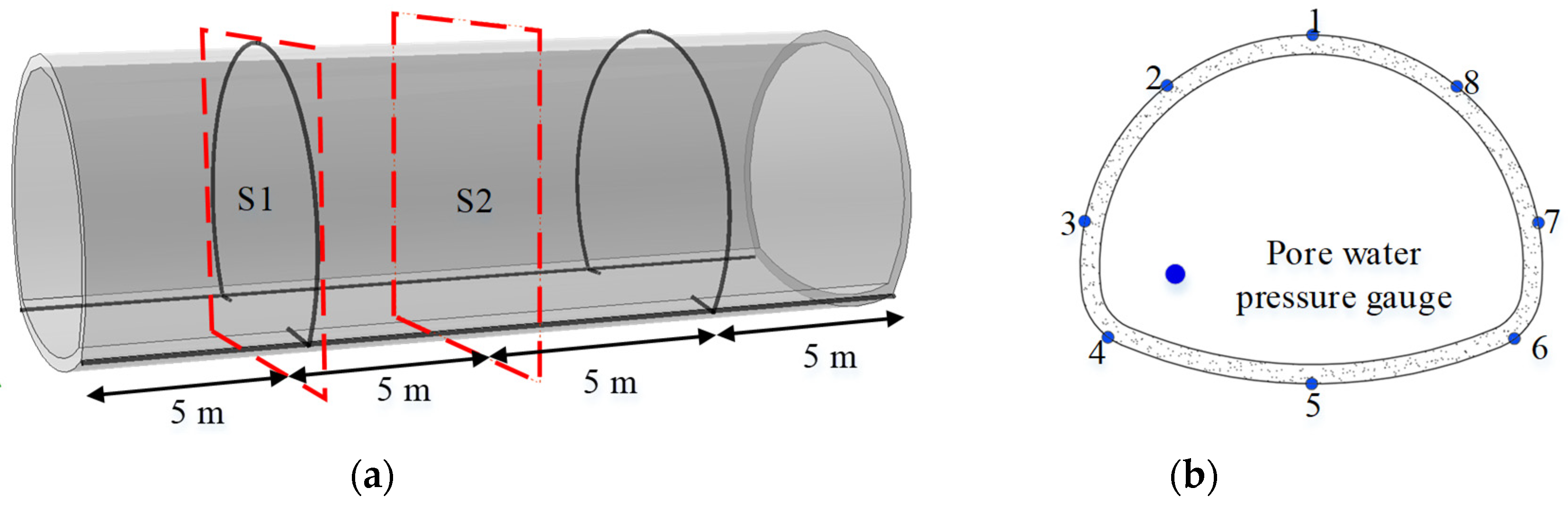
3.2. Reduced-Scale Model Setup
3.3. Test Procedures and Instrumentation
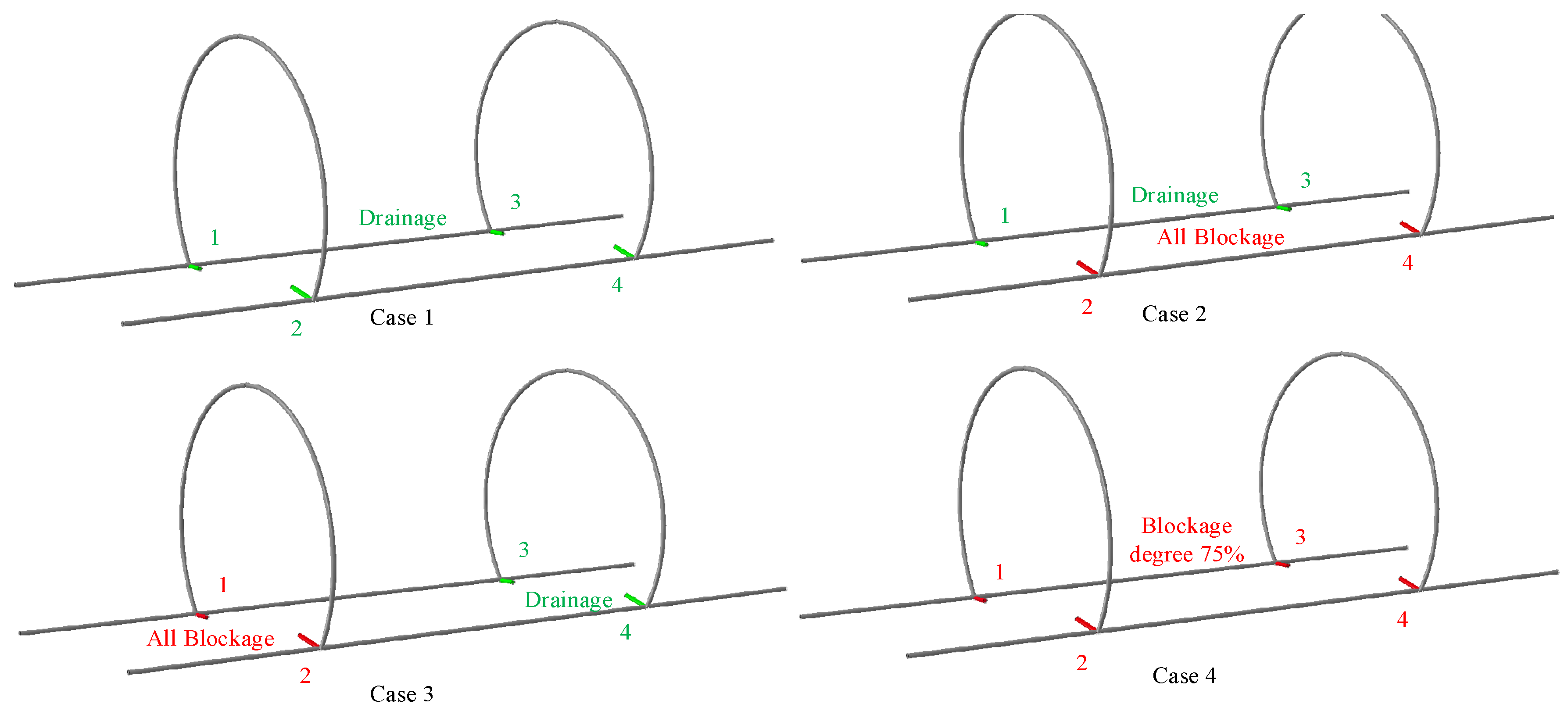
3.4. Test Conditions
- (1)
- The precast tunnel components, such as the drainage pipe, the drainage board, the initial lining, the secondary lining, etc., were installed.
- (2)
- The model box was incrementally filled with sand, layer by layer, and the height of each layer was 20 cm.
- (3)
- The water pressure gauges were placed at the predetermined points and connected to the data logger. Before the seepage test, the data acquisition system was debugged, and the numerical value of the water pressure gauge was calibrated and zero-adjusted.
- (4)
- After reaching the initial seepage field, the test started. The test results were recorded after the tunnel drainage, and the water pressure values of each measuring point were found to be stable.
4. Test Results
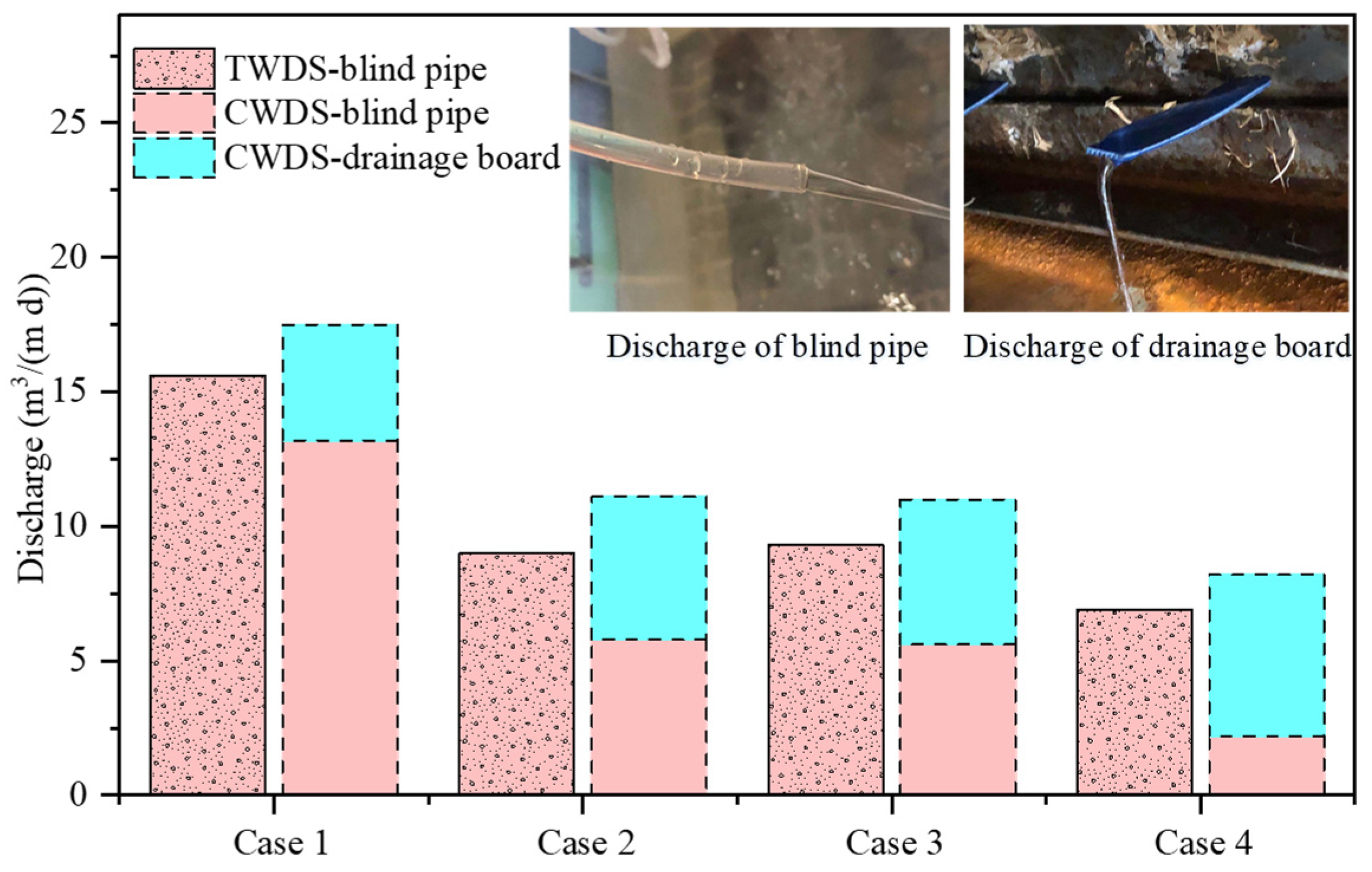
4.1. Discharge
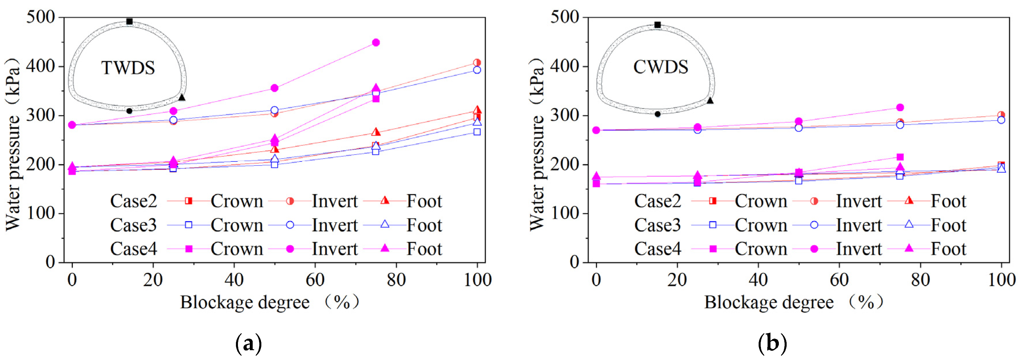
4.2. Distribution of Water Pressure
4.3. Evolution of Water Pressure
5. Conclusions
- (1)
- The decrease of drainage volume due to blockage of the drainage system is not linear; a partial blockage will cause a decrease in drainage volume, but the magnitude is not significant.
- (2)
- Installing a circular blind pipe behind the lining can significantly reduce the water pressure, but the influence of the range is limited and can only reduce the water pressure value within a certain range of the circumferential direction. A reasonable design of the drainage blind pipe can effectively reduce the overall water pressure outside the lining.
- (3)
- Compared with the one-side blind pipe blockage, the increase of water pressure caused by the blockage of the circumferential blind pipe was relatively small, indicating that the blockage of the circumferential blind pipe changes the groundwater infiltration path. However, it can still eventually converge into the longitudinal blind pipe and discharge into the tunnel through other paths. The effect of the longitudinal blind pipe on the water pressure is greater than that of the circumferential blind pipe, and the water pressure on the lining is greater when the longitudinal blind pipe is blocked on one side.
- (4)
- In the case of unblocked drainage, as TWDS can effectively reduce the water pressure, the effect of the CWDS with the addition of a drainage board behind the lining is not obvious, and it is only used as a safety guarantee at this time. Once the blind pipe is blocked, the drainage board can effectively reduce the water pressure on the lining.
Author Contributions
Funding
Conflicts of Interest
References
- Chen, G.Q.; Shi, Y.C.; Ji, F.; Li, T.B.; Wang, J.X.; Wang, Z.L. Corrosion investigation of groundwater for underground tunnel. Disaster Adv. 2013, 6, 228–235. [Google Scholar]
- Mao, Z.J.; Wang, X.K.; An, N.; Li, X.J.; Wei, R.Y. Water Disaster Susceptible Areas in Loess Multi-Arch Tunnel Construction under the Lateral Recharge Condition. KSCE J. Civ. Eng. 2019, 23, 4564–4577. [Google Scholar] [CrossRef]
- Yuan, J.Q.; Chen, W.Z.; Tan, X.J.; Yang, D.S.; Wang, S.Y. Countermeasures of water and mud inrush disaster in completely weathered granite tunnels: A case study. Environ. Earth Sci. 2019, 78, 576. [Google Scholar] [CrossRef]
- Gokdemir, C.; Li, Y.; Rubin, Y.; Li, X. Stochastic modeling of groundwater drawdown response induced by tunnel drainage. Eng. Geol. 2022, 297, 106529. [Google Scholar] [CrossRef]
- Xu, S.; Ma, E.; Lai, J.; Yang, Y.; Liu, H.; Yang, C.; Hu, Q. Diseases failures characteristics and countermeasures of expressway tunnel of water-rich strata: A case study. Eng. Fail. Anal. 2022, 134, 106056. [Google Scholar] [CrossRef]
- Zhang, Z.; Mao, M.; Pan, Y.; Zhang, M.; Ma, S.; Cheng, Z.; Wu, Z. Experimental study for joint leakage process of tunnel lining and particle flow numerical simulation. Eng. Fail. Anal. 2022, 138, 106348. [Google Scholar] [CrossRef]
- Zhu, Y.M.; Yang, H.P.; Huang, M.Q.; Wang, L. External hydraulic pressure and invert uplift study in a non-circular shallow tunnel. Tunn. Undergr. Space Technol. 2022, 122, 104345. [Google Scholar] [CrossRef]
- Arjnoi, P.; Jeong, J.-H.; Kim, C.-Y.; Park, K.-H. Effect of drainage conditions on porewater pressure distributions and lining stresses in drained tunnels. Tunn. Undergr. Space Technol. 2009, 24, 376–389. [Google Scholar] [CrossRef]
- Xiuying, W.; Zhongsheng, T.; Mengshu, W.; Mi, Z.; Ming, H. Theoretical and experimental study of external water pressure on tunnel lining in controlled drainage under high water level. Tunn. Undergr. Space Technol. 2008, 23, 552–560. [Google Scholar] [CrossRef]
- Cesano, D.; Olofsson, B.; Bagtzoglou, A.C. Parameters regulating groundwater inflows into hard rock tunnels—A statistical study of the Bolmen Tunnel in southern Sweden. Tunn. Undergr. Space Technol. 2000, 15, 153–165. [Google Scholar] [CrossRef]
- Holter, K.G.; Buvik, H.; Nermoen, B.; Nilsen, B. Future trends for tunnel lining design for modern rail and road tunnels in hard rock and cold climate. In Proceedings of the World Tunnel Congress (WTC)/39th General Assembly of the International-Tunnelling-and-Underground-Space-Association (ITA), Swiss Tunnelling Soc, Geneva, Switzerland, 31 May–7 June 2013; pp. 1435–1442. [Google Scholar]
- Barton, N.; Quadros, E. Some Lessons from single-shell Q-supported headrace and pressure tunnels. In Proceedings of the ISRM International Symposium-EUROCK 2020, Trondheim, Norway, 14–19 June 2020. [Google Scholar]
- Matsuo, S. An overview of the Seikan tunnel project. Tunn. Undergr. Space Technol. 1986, 1, 323–331. [Google Scholar] [CrossRef]
- Miura, K. Design and construction of mountain tunnels in Japan. Tunn. Undergr. Space Technol. 2003, 18, 115–126. [Google Scholar] [CrossRef]
- Yoo, C. Hydraulic deterioration of geosynthetic filter drainage system in tunnels—Its impact on structural performance of tunnel linings. Geosynth. Int. 2016, 23, 463–480. [Google Scholar] [CrossRef]
- Liu, J.H.; Li, X.J. Analytical solution for estimating groundwater inflow into lined tunnels considering waterproofing and drainage systems. Bull. Eng. Geol. Environ. 2021, 80, 6827–6839. [Google Scholar] [CrossRef]
- Luciani, A.; Peila, D. Tunnel Waterproofing: Available Technologies and Evaluation Through Risk Analysis. Int. J. Civ. Eng. 2019, 17, 45–59. [Google Scholar] [CrossRef]
- Murillo, C.A.; Shin, J.H.; Kim, K.H.; Colmenares, J.E. Performance tests of geotextile permeability for tunnel drainage systems. KSCE J. Civ. Eng. 2014, 18, 827–830. [Google Scholar] [CrossRef]
- Li, P.F.; Liu, H.C.; Zhao, Y.; Li, Z. A bottom-to-up drainage and water pressure reduction system for railway tunnels. Tunn. Undergr. Space Technol. 2018, 81, 296–305. [Google Scholar] [CrossRef]
- Kim, K.-H.; Park, N.-H.; Kim, H.-J.; Shin, J.-H. Modelling of hydraulic deterioration of geotextile filter in tunnel drainage system. Geotext. Geomembr. 2020, 48, 210–219. [Google Scholar] [CrossRef]
- Jang, Y.S.; Kim, B.; Lee, J.W. Evaluation of discharge capacity of geosynthetic drains for potential use in tunnels. Geotext. Geomembr. 2015, 43, 228–239. [Google Scholar] [CrossRef]
- Shin, J.H.; Lee, I.K.; Joo, E.J. Behavior of double lining due to long-term hydraulic deterioration of drainage system. Struct. Eng. Mech. 2014, 52, 1257–1271. [Google Scholar] [CrossRef]
- Mao, Z.J.; Wang, X.K.; An, N.; Li, X.J.; Wei, R.Y.; Wang, Y.Q.; Wu, H. Water leakage susceptible areas in loess multi-arch tunnel operation under the lateral recharge conditions. Environ. Earth Sci. 2020, 79, 368. [Google Scholar] [CrossRef]
- Gao, C.L.; Zhou, Z.Q.; Yang, W.M.; Lin, C.J.; Lia, L.P.; Wang, J. Model test and numerical simulation research of water leakage in operating tunnels passing through intersecting faults. Tunn. Undergr. Space Technol. 2019, 94, 103134. [Google Scholar] [CrossRef]
- Wang, H.X.; Huang, H.W.; Feng, Y.; Zhang, D.M. Characterization of Crack and Leakage Defects of Concrete Linings of Road Tunnels in China. ASCE-ASME J. Risk Uncertain. Eng. Syst. Part A-Civ. Eng. 2018, 4, 04018041. [Google Scholar] [CrossRef]
- Li, Z.; He, C.; Chen, Z.Q.; Yang, S.Z.; Ding, J.J.; Pen, Y. Study of seepage field distribution and its influence on urban tunnels in water-rich regions. Bull. Eng. Geol. Environ. 2019, 78, 4035–4045. [Google Scholar] [CrossRef]
- Zhou, Z.L.; Tan, Z.S.; Liu, Q.; Zhao, J.P.; Dong, Z.K. Experimental Investigation on Mechanical Characteristics of Waterproof System for Near-Sea Tunnel: A Case Study of the Gongbei Tunnel. Symmetry 2020, 12, 1524. [Google Scholar] [CrossRef]
- Zhang, Z.Q.; Chen, B.K.; Lan, Q.N. Experimental Investigation of Load-Bearing Mechanism of Underwater Mined-Tunnel Lining. J. Mar. Sci. Eng. 2021, 9, 627. [Google Scholar] [CrossRef]
- Zhao, J.P.; Tan, Z.S.; Zhou, Z.L. Discussion on the Waterproof and Drainage System of the Coastal Tunnel and Analysis of Water Pressure Law outside Lining: A Case Study of the Gongbei Tunnel. Adv. Civ. Eng. 2021, 2021, 6610601. [Google Scholar] [CrossRef]
- Li, Z.; Chen, Z.Q.; He, C.; Ma, C.C.; Duan, C.R. Seepage field distribution and water inflow laws of tunnels in water-rich regions. J. Mt. Sci. 2022, 19, 591–605. [Google Scholar] [CrossRef]
- Zhang, Z.Q.; Chen, B.K.; Li, H.Y.; Zhang, H. The performance of mechanical characteristics and failure mode for tunnel concrete lining structure in water-rich layer. Tunn. Undergr. Space Technol. 2022, 121, 104335. [Google Scholar] [CrossRef]
- Fu, H.L.; An, P.T.; Wu, Y.M.; Li, J.; Chen, L. Influence of asymmetric blockage of the drainage system of a deep-buried tunnel on water gushing. J. Mt. Sci. 2022, 19, 2075–2085. [Google Scholar] [CrossRef]
- He, B.G.; Li, H.; Zhang, X.W.; Xie, J.H. A novel analytical method incorporating valve pressure for the controlled drainage of transport tunnels. Tunn. Undergr. Space Technol. 2020, 106, 103637. [Google Scholar] [CrossRef]
- Nam, S.W.; Bobet, A. Liner stresses in deep tunnels below the water table. Tunn. Undergr. Space Technol. 2006, 21, 626–635. [Google Scholar] [CrossRef]
- Butscher, C. Steady-state groundwater inflow into a circular tunnel. Tunn. Undergr. Space Technol. 2012, 32, 158–167. [Google Scholar] [CrossRef]
- Li, D.Y.; Li, X.B.; Li, C.C.; Huang, B.R.; Gong, F.Q.; Zhang, W. Case studies of groundwater flow into tunnels and an innovative water-gathering system for water drainage. Tunn. Undergr. Space Technol. 2009, 24, 260–268. [Google Scholar] [CrossRef]
- Liu, S.Y.; Zhang, X.F.; Chen, X.G.; Wang, C.; Chen, Y.C. Exploratory Research on Drainage Structure of Highway Tunnel Based on Reducing the Risk of Crystallization Blockage. Processes 2022, 10, 1319. [Google Scholar] [CrossRef]
- Fan, H.B.; Zhu, Z.G.; Song, Y.X.; Zhang, S.Y.; Zhu, Y.Q.; Gao, X.Q.; Hu, Z.N.; Guo, J.Q.; Han, Z.M. Water pressure evolution and structural failure characteristics of tunnel lining under hydrodynamic pressure. Eng. Fail. Anal. 2021, 130, 105747. [Google Scholar] [CrossRef]
- Li, P.F.; Feng, C.H.; Liu, H.C.; Zhao, Y.; Li, Z.; Xiong, H.C. Development and assessment of a water pressure reduction system for lining invert of underwater tunnels. Mar. Georesour. Geotechnol. 2021, 39, 365–371. [Google Scholar] [CrossRef]
- Ll, A.; Jy, A.; Jfa, B.; Sw, A.; Cong, Z.C.; Mx, A. Experimental investigation on the invert stability of operating railway tunnels with different drainage systems using three-dimensional printing technology. J. Rock Mech. Geotech. Eng. 2022; in press. [Google Scholar]
- Stripple, H.; Bostrom, L.; Ellison, T.; Ewertson, C.; Lund, P.; Melander, R. Evaluation of two different drainage systems for rock tunnels. Tunn. Undergr. Space Technol. 2016, 58, 40–48. [Google Scholar] [CrossRef]
- Wang, Y.D.; Liu, Y.; Qi, C.F.; Zhou, T.Y.; Ye, M.; Wang, T. Crystallization law of karst water in tunnel drainage system based on DBL theory. Open Phys. 2021, 19, 241–255. [Google Scholar] [CrossRef]
- Chen, Y.F.; Cui, Y.; Barrett, A.G.; Chille, F.; Lassalle, S. Investigation of calcite precipitation in the drainage system of railway tunnels. Tunn. Undergr. Space Technol. 2019, 84, 45–55. [Google Scholar] [CrossRef]
- Liu, S.Y.; Zhang, X.F.; Gao, F. Anti-Blocking Mechanism of Flocking Drainage Pipes in Tunnels Based on Mathematical Modeling Theory. Coatings 2021, 11, 961. [Google Scholar] [CrossRef]
- Li, H.M.; Liu, S.Y.; Xiong, S.; Leng, H.; Chen, H.Q.; Zhang, B.; Liu, Z. Laboratory Experimental Study on Influencing Factors of Drainage Pipe Crystallization in Highway Tunnel in Karst Area. Coatings 2021, 11, 1493. [Google Scholar] [CrossRef]
- Eichinger, S.; Boch, R.; Leis, A.; Koraimann, G.; Grengg, C.; Domberger, G.; Nachtnebel, M.; Schwab, C.; Dietzel, M. Scale deposits in tunnel drainage systems—A study on fabrics and formation mechanisms. Sci. Total Environ. 2020, 718, 137140. [Google Scholar] [CrossRef]
- Guo, Y.P.; Leng, W.M.; Nie, R.S.; Zhao, C.Y.; Zhang, X. Laboratory evaluation of a new device for water drainage in roadside slope along railway systems. Geotext. Geomembr. 2018, 46, 897–903. [Google Scholar] [CrossRef]
- Zhang, S.; Bao, T.; Yoo, C.; Liu, C.; Li, P.; Chen, L. Design, Test, and Engineering Application of a Composite Waterproof and Drainage System in Tunnels. China J. Highw. Transp. 2021, 34, 198–208. [Google Scholar]
- Guo, Y.; Lin, C.; Leng, W.; Zhang, X. Laboratory evaluation of different geosynthetics for water drainage. Geosynth. Int. 2022, 29, 254–269. [Google Scholar] [CrossRef]
- Zhang, S.; Xu, Q.; Yoo, C.; Min, B.; Liu, C.; Guan, X.M.; Li, P.F. Lining cracking mechanism of old highway tunnels caused by drainage system deterioration: A case study of Liwaiao Tunnel, Ningbo, China. Eng. Fail. Anal. 2022, 137, 106270. [Google Scholar] [CrossRef]


| Parameter | Symbol | Formula | Ratio | Unit |
|---|---|---|---|---|
| Dimension | l | αl | 1:40 | m |
| Weight | γ | αγ | 1:1 | N/m3 |
| Permeability coefficient | k | αk | 1:1 | m/s |
| Water pressure | P | αP = αγαl | 1:40 | kPa |
| Time | t | αt = αl/αk | 1:40 | s |
| Discharge | Q | 1:1600 | m3 |
| Working Conditions | Description |
|---|---|
| Case 1 | All four drainage outlets are not blocked. |
| Case 2 | The drainage outlets 1 and 3 are not blocked, while the blockage degree of drainage outlets 2 and 4 increases incrementally, from 0, 25%, 50%, 75% to finally, 100% blockage. |
| Case 3 | The drainage outlets 3 and 4 are not blocked, while the blockage degree of drainage outlets 1 and 2 increases incrementally from 0, 25%, 50%, 75% to finally, 100% blockage. |
| Case 4 | The blockage degree of all four drainage outlets increases incrementally from 0, 25%, 50% to finally, 75% blockage. |
Publisher’s Note: MDPI stays neutral with regard to jurisdictional claims in published maps and institutional affiliations. |
© 2022 by the authors. Licensee MDPI, Basel, Switzerland. This article is an open access article distributed under the terms and conditions of the Creative Commons Attribution (CC BY) license (https://creativecommons.org/licenses/by/4.0/).
Share and Cite
Bao, T.; Zhang, S.; Liu, C.; Xu, Q. Experimental Study on the Effect of Hydraulic Deterioration of Different Drainage Systems on Lining Water Pressure. Processes 2022, 10, 1975. https://doi.org/10.3390/pr10101975
Bao T, Zhang S, Liu C, Xu Q. Experimental Study on the Effect of Hydraulic Deterioration of Different Drainage Systems on Lining Water Pressure. Processes. 2022; 10(10):1975. https://doi.org/10.3390/pr10101975
Chicago/Turabian StyleBao, Tong, Sulei Zhang, Chang Liu, and Qing Xu. 2022. "Experimental Study on the Effect of Hydraulic Deterioration of Different Drainage Systems on Lining Water Pressure" Processes 10, no. 10: 1975. https://doi.org/10.3390/pr10101975
APA StyleBao, T., Zhang, S., Liu, C., & Xu, Q. (2022). Experimental Study on the Effect of Hydraulic Deterioration of Different Drainage Systems on Lining Water Pressure. Processes, 10(10), 1975. https://doi.org/10.3390/pr10101975