Abstract
Electrical discharge coating (EDC) process is used to deposit material on workpiece surface from sacrificial or green compact tool electrode in an electrical discharge machine. The paper presents the mechanism of EDC using green compact electrode and powder mixed dielectric methods. The tool electrode material, electrode size, process parameters, and type of dielectrics can directly affect the surface integrity of workpiece. Here, a process map of EDC as a function of process parameters, its classification, advantages, and applications for a wide range of engineering materials offers a proper template for the evaluation of coating phenomena. This study shows that EDC is an economic process as compared to other costlier techniques. Additionally, the effect of various EDM and EDC parameters on surface integrity and tribological behavior of deposited coatings is studied with their pros and cons. Finally, the current research trends of EDC and its challenges are elaborated.
Keywords:
surface modification; coating; EDM; EDC; green compact; powder mixed dielectric; morphology; current; hardness; wear 1. Introduction
Surface modification is the most flexible and effective technique to resolve the tribological issues found in any machinery [1]. It improves the tribological performance by increasing the hardness, alternating the surface characteristics, and decreasing the coefficient of friction. Tribological properties of machine components, such as sliding bearings, valves, seals, metal cutting, and forming tools, can be enhanced by surface modification [2]. In this regard, electrical discharge coating (EDC) is an advanced and simple coating process that is applied for conductive materials due to the certain advantages, i.e., good adhesion among the parent material and coating, high efficiency to achieve thick coating, and ability to balance the composition of coated layer by using proper tool electrode material and dielectric fluid [3,4]. EDC is a potential process for the coating of different workpiece materials according to the demand, such as wear- and corrosion-resistant coating on the surface of aluminum, molds, and dies [5];solid lubricant coating on steel surface [6]; TiC/Fe cermet coating on stainless steel [7]; and wear-resistant TiC coating on roll surface [8]. EDC works on the principle of electro-discharge machining (EDM), which is a material erosion process, applied to generate complex parts of machine, tools, dies, and molds [9,10,11,12]. In EDC process, electrical energy converts into thermal energy by producing electric sparks between the parent material and compact electrode (tool) submerged in the hydrocarbon oil [13,14,15]. The material for coating is given by a sintered green compact electrode, which permits easy transfer of material for coating deposition on electrically conductive workpieces. At a high temperature, the occurrence of a chemical reaction between electrode materials and hydrocarbon causes the formation of a coating layer over the parent material [15,16,17]. Additionally, owning to melting and ejection of electrode materials, the material transfer occurs, and compacted materials deposit on the substrate. This process was recently employed by researchers to obtain desirable coating through continuous electrical sparks in EDM [18].
The process is classified under thick and thin EDC. Thin EDC process can be used on workpiece to attain the thickness of recast layer in microns [19,20]. Removal of the material along with addition takes place together in this type of coating [21]. By using a TiC electrode, a layer of 8 μm thickness was formed [15]. Thick EDC, also referred as “MSCoating”, can be deposited over the components to repair them [22,23]. In contrast to thin coating, coating layer thickness in thick EDC is not restricted to the recast layer and allows for large deposition, similar to the laser cladding method. In this process, a sequence of materials layering is a chain process. In this regard, satellite coatings were generated in EDC [21]. A cobalt coating of 1 mm thickness was applied by Goto et al. (2004) [23] and a Ni coating of 3.5 mm thickness by Araki et al. (2008) [24].
With ongoing researches on surface coating, various other surface modification processes such as ion implantation [25,26], electroless plating [27], electrodeposition [28], thermal spraying [29,30], chemical and physical vapor deposition [31,32], and laser cladding [33,34], have been proposed for emphasizing the characteristics of workpiece surface. However, these processes demand a dedicated setup with a complex arrangement that leads to more production cost [35,36,37]. In a comparison of chemical vapor deposition and physical vapor deposition, electrical discharge coating can be preferred due to its ability to control the coating thickness, no requirement of a special vacuum apparatus with high-temperature devices [38], and creation of a hard layer of different materials using the EDM tool electrode [39]. The EDC process has the capability of machining and coating the substrate using the same tool electrode simultaneously. Hence, it is possible to use different shapes of an electrode for making complex components. At the same time, high-temperature plasma forms an electrical discharge process that can be effectively applied to prepare the coating of metals with a high melting point (hard-to-process ceramics materials) on a base material. Therefore, the wear-resistant ceramic coating layer on complex-shaped parts used in various machine components can easily be to fabricated to enhance the lifespan [7].
This paper presents the various past research works on electrical discharge coating formation by green compact tools and powder mixed dielectric conditions. The mechanism of EDC is discussed, and the effect of coating and machine parameters on the improvement in surface characteristics is explained. Afterwards, different changes in mechanical and metallurgical properties associated with the EDC coating using a different combination of material are reported. Analysis of surface integrity, microhardness, and tribological issues of the EDC coating deposited using a different combination of material is addressed. Finally, the recent developments of electrical discharge coating and the impending scope of its future work are discussed.
1.1. Need for Coatings on Engineered Surfaces
The annual cost of frictional energy losses in the industry is found to be 5–7% of the gross domestic product in industrialized countries, and it contributes approximately one-third of world’s energy resources [40]. Additionally, excessive wear results in a scrap of hundreds of thousands of parts every year and 10% of oil consumption is utilized to compensate for friction in the United States [41]. The friction reduction in the engine parts of the vehicle could reduce about 5% global consumption of fuel annually accompanied by decreasing the CO2 emissions by around 250 million tons annually [40]. Therefore, from both environmental protection and energy losses, it is a major issue to solve the friction and wear loss by coating layer formation process [42]. By the application of the coatings, the wear and friction losses can be efficiently improved. Therefore, the obvious goal of using tribological coatings is to increase lifetime. These coatings can be utilized in various effective ways, such as:
- (1)
- An improvement in wear resistance properties of cutting tool to enhance productivity [2].
- (2)
- Fabrication of hard and wear-resistant coating on a component made of low weight and strength for a higher power to weight ratio [2].
- (3)
- Fabrication of solid lubricant coatings to reduce frictional force, which allows for lower consumption of fuel and is also beneficial for applications in brakes, bolted joints, and safety connectors [2].
- (4)
- Application of coatings in many sliding components to reduce the tendency of sticking [2].
1.2. Methods of Coating, Advantages, and Limitations
At present, there are many coating methods available for surface modification to improve the tribological properties. These coating methods can be classified according to the state of the deposited material during the process (Figure 1a) and the obtained coating thickness (Figure 1b). Electro spark deposition, laser cladding, and thermal spraying are classified as thick coating process in which material is deposited in the molten state. Vapor deposition (PVD and CVD) and plating (electro/electroless plating) are used for thin layer deposition. In the vapor deposition technique, the gaseous state of a material is maintained, and in the plating process, the material solution is used.

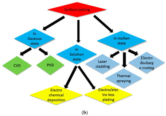
Figure 1.
Classification of coating process according to (a) state of material in the deposition process and (b) coating thickness.
1.2.1. Electroless Plating
Electroless plating is defined as a process for deposition of uniform metallic coating layer over the bulk surface by chemical reduction of metal ions in the presence of aqueous solution without applying electrical energy. In this process, the chemistry of deposition bath is to be maintained in such a way that kinetic motion of the electrons’ transfer towards metal ion is established. A catalyst is applied for accelerating the rate of reduction in metal ion. In this way, the reduction of the ions takes place over the substrate surface, and the coating is obtained [43]. Electroless plating exhibits advantages for coating non-electrochemically conductive material. However, the process is time consuming and it can only be applied to certain materials. Additionally, adhesion coating strength is not satisfactory for many applications [44].
1.2.2. Electrochemical Deposition
Electrochemical deposition (ECD) is an old process to form the layers of metal on the conducting parent material. In ECD, a thin coating layer is achieved when dispersed particles in a liquid between the parent material and the second electrode are subjected to an electrical field [45]. Further, electrodeposition involves the adjustment in some factors (pH, current density, bath composition, and temperature), which is required to obtain the proper grain size [46,47]. The strategies involved in electrochemical offers include some important benefits and unique probability in the synthesis of both nanostructures and nanomaterials. An electrically conductive coating of nano thickness from 10 nm to greater than 100 μm can be fabricated [48]. The deposition method needs direct electrical contact with the parent material when it is immersed in a liquid bath, and the process tends to non-conformal growth on non-planar surfaces.
1.2.3. Chemical Vapor Deposition (CVD)
The CVD process is used to generate coating of high-performance, high-quality, solid materials, normally under vacuum. Its applications are found in the semiconductor industry to fabricate thin coatings. In these processes, gases flow into a chamber, pass over the heated substrate, and decompose into a solid phase that deposits them, forming thin films onto the base material [49]. Recently, the CVD technique has been used for the production of 0.25 mm thick molybdenum tubes for nuclear fuel cladding applications in which a slow deposition rate is employed for a long duration (<50 h) [50]. So, this process is very slow, and sometimes reactions are incomplete.
1.2.4. Physical Vapor Deposition (PVD)
PVD is applied to generate a thin film of metals and its alloys with a thickness range from 1 to 10 µm. The process involves physically transfer of ions, atoms, or molecules of coating materials onto a parent material. This coating method involves vacuum evaporation of coating at high temperatures with subsequent condensation in vacuum [51]. PVD coatings are commonly promoted owning to higher chemical affinity, but they enhance abrasive resistance to wear. One of the major applications of PVD is a deposition of the coating on cutting tool when the coating material is removed physically by a source through sputtering or evaporation. In spite of various advantageous of PVD, there is a requirement of a special vacuum apparatus, and technologies typically operate at very high temperatures. Additionally, the deposition rate of this coating method is very slow [52].
1.2.5. Plasma Arc Coating
In this coating method, an arc is generated to develop a plasma between two electrodes. The heated plasma starts moving through the nozzle and has impact over the substrate. In recent research, a Ti-Zr coating was obtained by arc-plasma deposition in a vacuum in which the nano hardness of coating was increased with a higher percentage of Zr. Additionally, the nanoindentation test showed a significant enhancement of the failure elastic strain and resistance to plastic deformation of coating along with the higher Zr content (11 wt% to 22 wt%) [53]. A variety of substrate materials that include metals, composite, glass, plastics, and ceramics were deposited using plasma spray. Additionally, a plasma jet of plasma can be used for the coating of refractory metals, ceramics, ZrO2, B4C, and W. This process can also be applied to coat the internal surface of cylindrical parts and the external surface of any geometry. The equipment of the plasma arc coating cannot be operated manually, and it requires automated gun manipulators [54].
1.2.6. Laser Cladding
Laser cladding is a progressive technology for adding one or more materials over the surface in a controlled manner by scanning the laser beam onto the powder bed for improving the various surface properties. Cladding is an advantageous technique to coat the whole workpiece with certain materials that have excellent characteristics. A thin surface layer of desirable material is melted with a parent material using laser irradiation that generates a functional coating having an excellent metallurgical bond with the parent material [55,56,57,58]. A thin surface layer is formed due to the melting of preplaced or fed powder through a laser beam that exhibits a strong bong with the base material. Previously, a brittle crack-free coating of amorphous Fe was also obtained by laser cladding. They suggested that the crack generation can be avoided when a triple laser scanning technique is performed [59]. In laser, the cost of the laser is high, and the interaction time is short, which restrict its application for alloys that require heat treatment and a long soaking time. Further, considering the issue of high speed and advance heating in laser cladding, little deformation leads to residual stress generation over the surface.
1.2.7. Electrical Discharge Coating (EDC)
EDC is extensively used as an economically viable coating technique that uses electrical discharge processes to deposit coating material on the substrate surface. This process improves the wear resistance and hardness properties with the use of the negative polarity of EDM to retain a coated layer on top of the workpiece [60]. In this process, coating thickness can be controlled significantly without any need for special equipment [6]. Additionally, EDC does not require a complicated set-up and arrangement for its operation. This process can also be defined as a non-conventional coating technique in which hard layers of coating are achieved by depositing the carbides of Ti, Cr, W, etc. [61] through transferring the tool electrode material by the application of a compact tool electrode. This method of modifying the surface attracted the researchers directly towards the surface modification especially for electrical discharge texturing with tools made of WC/Co and TiC/WC/Co, etc. [62,63,64,65,66,67,68].
1.3. Comparison between EDC and Other Processes
Different techniques have been propped for the preparation of coating, e.g., ion plating [69], laser cladding [70], magnetron sputtering process [71], and vapor deposition methods [72]. The set-ups used in these processes need skilled labor, high investment, and a vacuum atmosphere. EDC has many benefits over these techniques: (1) no need of extra set-up, (2) metal matrix composite coating preparation is possible over any conductive surface, (3) coating of hard to process ceramics [73], (4) coating of complex shapes [74], (5) no requirement of toxic chemicals [75,76], and (6) ability to prepare thin and thick coating [77]. Many other advantages of EDC are given in Section 2.2.1 [78]. Researchers summarize the comparison of various types of coatings [79]. Table 1 summarizes the comparison between EDC and other processes. Electroless plating is defined as a process for deposition of a uniform metallic coating layer over the bulk surface (sample) by chemical reduction of metal ions in the presence of aqueous solution without applying electrical energy. Electroless plating exhibits advantages for coating non-electrochemically conductive material. However, the process is time consuming and it can only be applied to certain materials. Additionally, adhesion coating strength is not satisfactory for many applications [44]. Similarly, electrochemical deposition (ECD) is also an old process to form the layers of metal on the conducting parent material. In ECD, a thin coating layer is achieved when dispersed particles in a liquid between the parent material (working electrode) and the second electrode (reference electrode) are subjected to an electrical field [45]. Further, electrodeposition process involves the adjustment in some factors (pH, current density, bath composition, and temperature), which is required to obtain the proper grain size [46,47]. The deposition method needs direct electrical contact with the parent material when it is immersed in a liquid bath, and the process tends to non-conformal growth on non-planar surfaces.

Table 1.
Summary of comparison between EDC and other coating techniques [35,36,37,79].
Further, the CVD process is used to generate coating of high-performance, high-quality, solid materials, normally under vacuum. Its applications are found in the semiconductor industry to fabricate a thin coating. In these processes, gases flow into a chamber pass over the heated substrate and decompose into a solid phase that deposits them, forming thin films onto the base material [49]. Still, the CVD process has its own limitations, namely that the process is very slow and sometimes reactions are incomplete. Similarly, PVD is applied to generate a thin film of metals and its alloys with a thickness range from 1 µm to 10 µm. The process involves the physical transfer of ions, atoms, or molecules of coating materials onto a parent material. This coating method involves vacuum evaporation of coating at a high temperature with subsequent condensation in the vacuum [51]. One of the major applications of PVD is a deposition of the coating on a cutting tool when the coating material is removed physically by a source through sputtering or evaporation. In spite of various advantageous of PVD, there is a requirement of a special vacuum apparatus, and technologies typically operate at very high temperatures. Additionally, the deposition rate of this coating method is very slow [52].
Further, a variety of substrate materials that include metals, composite, glass, plastics, and ceramics were deposited using plasma spray. In plasma spraying, an arc is generated to develop a plasma between two electrodes. The heated plasma starts moving through the nozzle and has an impact over the substrate. This process can also be applied to coat the internal surface of cylindrical parts and the external surface of any geometry. The equipment of the plasma arc coating cannot be operated manually, and it requires automated gun manipulators [54]. Out of these thechinques, one of the processes is laser cladding, which is a progressive technology for adding one or more materials over the surface in a controlled manner by scanning the laser beam onto the powder bed for improving the various surface properties. A thin surface layer of desirable material is melted with a parent material using laser irradiation that generates a functional coating having an excellent metallurgical bond with parent material [55,57,80,81]. In laser, the cost of the laser is high, and the interaction time is short, which restricts its application for alloys that require heat treatment and a long soaking time. Further, considering the issue of high speed and advanced heating in laser cladding, little deformation leads to residual stress generation over the surface.
Recent developments in the field of surface coating have led to a renewed interest in electrical discharge coating (EDC), which uses electrical discharge processes to deposit a coating material on the substrate surface. EDC is performed by adapting the electrical discharge machining (EDM) process with a green compact tool electrode (prepared by powder compaction in hot mounting press) and workpiece [82]. With the help of a green compact electrode and high-temperature generation during the event of sparking, a broad range of materials can be used to melt and deposit on the metal surfaces. The metal particles stripped from the W-Cu-sintered electrode get combined with the disintegrated carbon released from the kerosene oil to form cemented WC. Accordingly, the compounded of the cemented WC can be deposited over the workpiece surface, resulting in a modified effect during EDM [83]. Researchers summarize the comparison of various types of coatings [79]. Table 1 summarizes the comparison between EDC and other processes.
2. Background and Description of EDC
2.1. Origin of Electrical Discharge Coating (EDC)
Going back to 1770s, Joseph Priestly, an English scientist, investigated the erosion action of spark/electrical discharges. Many attempts were done in 1930s to machine hard metals like diamonds by applying electrical discharges. These intermittent spark discharges lead to erosion, which occurs in the presence of air in between the workpiece and tool electrode connected to a DC power supply. These processes were not very precise due to overheating of the machining area and may be defined as “arc machining” rather than “spark machining” (Ho and Newman, 2003) [84]. During World War II, pioneer experiments on EDM were performed in 1943 at the Moscow University by two Russian scientists, N.I. and B.R. Lazarenko, and a controlled method to machine material was developed when the destructive effect of these spark discharge was channelized. In 1950s, a resistance–capacitance (RC) relaxation circuit was presented as a successful model in EDM, providing a consistent reliable controller of pulse times along with an easy servo control circuit to automatically adjust the spark gap between the tool and the workpiece [85].
In 1975, it was suggested that, during the EDM process, both the tool electrode and workpiece are subjected to intense heating at the local vicinity in the plasma channel. As a result of this high-power density, some material gets eroded from both the tool and workpiece by local heating and melting. Further, they established that, for the need of high erosion rate along with good quality surface, erosion from a tool electrode was not desirable. Hence, they reported that a proper selection of tool material and machining process parameters (peak current, pulse width, and polarity) was extremely essential [86]. Moving forward to 1980s, the idea of incorporating the computer numerical control (CNC) in EDM was brought about, which led to incredible developments in enhancing the machining efficiency. CNC facilitates total EDM, which implies an automatic and unattended machining from inserting the electrodes in the tool changer to a finished, polished cavity or cavities. These growing benefits of EDM were later intensely required by the manufacturing industries to achieve enormous economic profits and generate keen research interests [87]. Figure 2 illustrates the line diagram for the component of the EDM process that includes major components like the CNC input, pulse controller, and servo system. The gap controller is attached in modern EDM machines that control the inter-electrode distance, which is needed for stable sparking. The various input machine parameters are loaded manually in the machine through a CNC EDM control panel. The high voltage (gap voltage) across the spark gap is established, and the breakdown of the current (gap current) occurs. The spark generation across the electrodes results in the erosion process. An intelligent routine is required to sense an arc or short circuit and temporarily switch off the circuitry, which is known as the ‘‘pulse controller’’. The pulse controller helps in sending a command to a power module, which produces a high voltage pulse that results in the erosion process. A higher efficiency of the process will be possible using an efficient pulse controller due to a higher percentage of normal pulses. The precise detection of normal pulses causes the production of a large number of eroding pulses in a single operation. By precise detection of normal pulses, the extension of the pulse off-time causes a lower frequency of short circuits and more frequent pulses. Therefore, a larger amount of pulses occurs, and more erosion takes place in the same period. Inside the pulse controller, there is a pulse discrimination routine to detect the harmful pulse and then accordingly switch off the gap current. The pulse discrimination technique is especially important for EDM with a non-rotating electrode design where the machining occurs by controlling the motion of tool electrode placed near to the work surface [88].
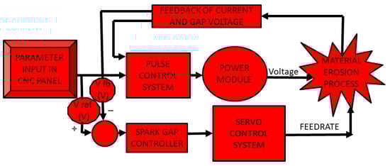
Figure 2.
Line diagram for EDM control system [84].
Jeswani (1981) carried out various experiments with the addition of fine graphite powder (4 g/L) in the dielectric, which resulted in an improved material removal rate (MRR) of a 60% and 15% reduction in the electrode wear ratio [89]. Dry and near-dry electrical discharge machining EDM processes use gas and liquid–gas mixtures, respectively, as a dielectric medium to substitute the liquid dielectrics in conventional EDM. The dry EDM was first reported in a short NASA technical note 1 in 1985 for hole drilling using argon or helium gas as a dielectric medium [90]. On the other hand, it has been revealed that the machined surface produced by EDM with a silicon electrode has remarkable corrosion and wear resistance [91].
Gangadhar, et al. (1991) studied the modified surface topology of mild steel when bronze compacts with 90% Cu and 10% Sn were used for reverse polarity in EDM. The X-ray diffraction plot revealed the formation of Cu3Sn, Cu6Sn5, Cu, and Sn. They reported the possibility of change in metallurgical and chemical behavior of the mild steel due to easier transportation of the tool material by the plasma. The physicochemical and metallurgical nature of the mild steel surface can be changed by appropriately changing the configuration of the powder compact. Those surfaces showed numerous craters, and comparatively big craters were observed over the bronze-coated surface. Using compact tools of bronze, the energy associated with an individual discharge was high as the spark took place through large asperities. Additionally, the lower melting temperature and the higher fluidity of melted bronze than those of the melted low-carbon steel layer resulted in the large size of the crater [67]. In 1992, EDC was also employed with a TiC-sintered tool to analyze the microhardness, coating thickness, surface roughness, and wear performance of the coated layer deposited on the roll surface. It was desirable for the better service life of the roll for industrial applications for consistent control in surface texture. The method of skin-pass rolling was used for the evaluation of steel sheet surface texture by maintaining the roll surface topography. The effect on the clarity of coating and formability of sheet press was studied. A hard layer was formed by EDC with TiC electrode, which showed a Vickers hardness of greater than HV1500 and controllable surface roughness. The wear of coated rolls generated was greater than the chrome-plated rolls [92]. Mohri, et al. (1996) provide a new thought to the EDM mechanism by employing a secondary electrode, which can facilitate the sparking phenomenon in insulating ceramics. Both wire EDM and EDM were successfully tested for diffusing conductive particles from assisting electrodes over the surface of Sialon ceramics or silicon nitride (Si3N4) [93].
Kunieda and Yoshida (1997) conducted a study on dry EDM using a copper tool and steel workpiece, which revealed that, in the case of EDM in air, the wear ratio of the tool was lower and material removal was greater when the tool was at negative polarity. However, in the case of EDM in liquid, there was more tool wear and lower material removal when the polarity of the tool electrode was negative. Therefore, a negative polarity of tool was found to be desirable to enhance the material transfer from the tool [94]. Wang, et al. (2002) found the EDC application in surface repairing and strengthening molds and cutting tools when they carried out experiments over the steel with titanium powder compact electrodes at negative polarity. The deposited coating thickness of up to 20 µm showed that the microhardness of the workpiece was increased from 332 HV to 2200 HV at the optimal setting of the discharge current (4A and discharge duration; 8 µs). The reason for enhancement in this hardness is due to carbide formation after the reaction of titanium with a carbon of the dielectric. In this regard, the presence of 51% TiC and 48% Fe in the coated surface was observed through X-ray diffraction analysis [74]. Further work on EDC reported the use of multi-layer electrode when titanium carbide (TiC) could be used to coat the graphite layer on the nickel workpiece with the help of a multi-layer electrode. The experimental results give the formation of TiC due to a large amount of carbon from the graphite layer, which enhances the carbon concentration with an increase in the hardness of coating [95]. Moreover, the TiN ceramic coating was prepared using dry EDC in which high discharge energy resulted in a coarser layer along with the presence of a weak phase of Ti2N and a slight AlN phase. Additionally, the presence of a few voids was also observed owing to uneven coverage and cracks formed as a result of the mismatch of thermal expansion between the Al and TiN matrix. Additionally, TiN grains adhered over the Al alloy as a result of insufficient energy. Considering EDC, the optimum selection of discharge parameters could allow Ti particles to react with N2, and at that time, a TiN film can homogeneously be deposited over the Al alloy [96]. Figure 3 summarizes the chronology of the events in the development of EDM/EDC technology. Hence, recent developments in the field of surface coating have led to a renewed interest in electrical discharge coating (EDC), which is emerging as an economically viable coating technique that uses the electrical discharges process to deposit coating material on the substrate surface. EDC is performed by adapting the EDM process with a tool electrode and workpiece, held at negative and positive potentials, respectively [82]. The working principle, advantages, and applications of EDC are elaborated in next section.
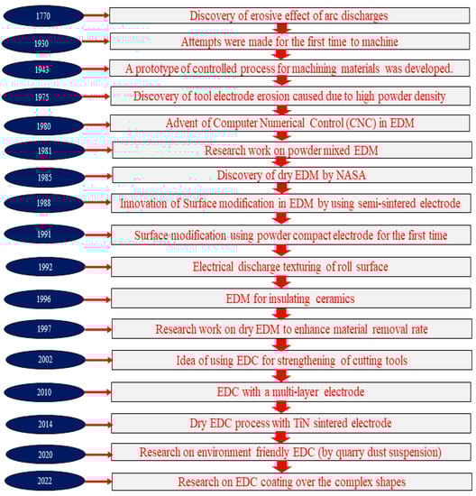
Figure 3.
Chronology of EDC origin.
2.2. Working Principle of EDC
To understand the EDC principle, a brief introduction about the EDM working principle is needed. Basically, EDM is a technique of material removal from the surface of a conductive material. According to the working principle, the process starts with a large number of discrete spark discharges of high frequency between electrodes maintaining an open voltage, submerged in a dielectric medium, and with a small gap distance of 0.025–0.102 mm [82]. For the dielectric breakdown to occur, an ignition delay time takes place that depends upon the gap conditions; the statistical time-lag is needed to generate the electrons and the time required for ionization of the dielectric fluid [97]. This breakdown causes the electrons to move towards the anode. The impact of these electrons with the particles in the dielectric fluid results in the formation of positive ions and a greater number of electrons, which move in the direction of cathode and anode, respectively (Figure 4a). Localized plasma is generated at a high temperature and localized pressure [98]. This process results in spark generation; hence, the heat generation takes place as the electrons with high velocity impact upon both the electrodes. The outcome of the impact follows the vaporization and melting of material from the electrodes. Some portion of melted material left over from the component’s surface re-solidifies and deposits over the workpiece. This is termed as the recast layer, which has high microhardness, good adhesion, and is corrosion resistant. Here, the dielectric type also plays an important role, as it is observed that the recast layer thickness is affected by the dielectric type because the volume of molten metal flushed is different for different dielectrics. For example, the recast layer thickness in water is higher as compared to those forms in kerosene with the same pulse duration due to the fact that water emulsion exhibits higher viscosity as compared to kerosene; therefore, it is not possible to remove the molten material, and at the end it builds up over the sample surface. Additionally, recast layer deviation increases with an increase in pulse duration and peak current because the material removal rate is greater at a higher pulse duration. However, certain detrimental effects are also generated with recast layer formation [99].
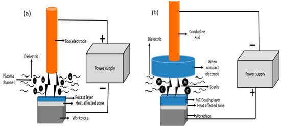
Figure 4.
(a) EDM mechanism and (b) EDC mechanism.
EDC is a process of depositing the coating layer over the workpiece material from the green compact electrode and powder mixed technique through a large number of spark discharges between the powder compact electrode and workpiece. Prior to the preparation of EDC process, the binding material with a coating material of the required amount is used in the powder mixture to easily make the compact with high strength. Then, after mixing the powder mixture for a sufficient amount of time, the powder is compressed in a mounting press. For the coating formation in die-sinking EDM, the powder compact electrode is negative and a workpiece is positive. This reverse polarity with an optimal combination of process parameters assists in the maximum blending of the compact electrode material with the parent material. Hence, as compared to EDM, a recast layer (coating layer) of higher thickness is obtained during EDC when the reverse polarity is used. Goto, et al. (2003) found that the formation mechanism of thin EDC comprises an electrical discharge due to the heat generation and forms a melt pool and crater over the substrate due to the removal and vaporization of the material. The spark discharges cause the wear of the electrode materialremoved due to the impact of spark and by the heating effects of the local melting, which is then attached to the substrate.
Figure 4a,b shows the coating formation over the workpiece surface associated with EDM and EDC, respectively. From Figure 4b, it can be said that the series of multiple sparking events allows for a continuum to be formed as a multi carbide (MC) layer across the workpiece. Hence, the process of workpiece surface modification by transferring the metal from the electrode towards the workpiece in the EDM machine is simply referred to as an electrical discharge coating (EDC). A thick and hard material carbide layer is formed over the substrate (Figure 4b) [100]. In EDC, it is noticed that the removal of material in each pulse is restricted due to carbon deposition over the tool. The effect of carbon layer leads to the use of a tool at a positive polarity in EDM. Therefore, in the case of EDC, the compact tool is used at a negative polarity as the removal of material from the tool is required to be higher and not restricted by the carbon formation. The recast layer thickness obtained in EDC is higher than EDM as a result of reverse polarity and loosely bonded particles in the green compact tool electrode. Hence, EDC is adapted as an application of EDM by using the powder compact tool electrode and powder mixed EDM of the desired powder material. The surface integrity of the coating and tribological characteristics can be well controlled by the proper selection of process parameters [101,102]. In short, Liu, et al. [79] also summarize the difference between the EDM and EDC processes, as shown in Table 2.
Table 2.
Difference between machining and coating.
There are many theories illustrated for material transfer in EDC [97,103]. According to the present theory of the phenomenon of electrical spark, the sparking in EDM leads to the localized melt pools’ (partially or fully melted) formation over the workpiece. In EDC, this melt pool further combines with dissociated material particles of the compact electrode and then they rapidly cool down to form a deposited layer. As shown in Figure 5, general descriptions of electrical spark discharge suggest that materials are released from the melt pools onto both the parent material and tool electrode at the end of an electrical discharge. The ejection of material particles results in lowering the break down voltage, which promotes a spark in that location, where these particles merge with the melt pools associated to the next spark. The intermixing and solidification of individual deposits helps in building a continuum coating layer, as shown in Figure 5 [15]. In this way, series of sparking events can lead several overlapping layers to form a hard and wear-resistant continuum coating layer over the workpiece surface.
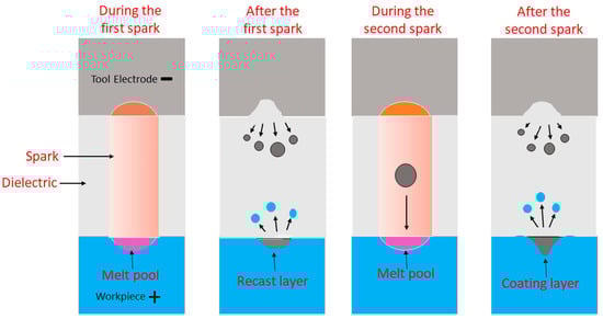
Figure 5.
Mechanism of material transfer [15].
2.2.1. Advantages of EDC
- (1)
- The hard recast layer in EDM generally contains cracks, caused by the presence of residual stresses, which diminish the corrosion and wear resistance of components manufactured through EDM [104]. To remove and to restore the surface properties in the damaged layer, the EDC process is needed.
- (2)
- The recast layer thickness obtained in EDC is higher than EDM as a result of reverse polarity and loosely bonded particles in the green compact tool electrode. This reverse polarity with an optimal combination of process parameters assists in the maximum blending of the compact electrode material with parent material. Hence, EDC is adapted as an application of EDM by using the powder compact tool electrode and powder mixed EDM of the desired powder material.
- (3)
- The surface integrity of the coating and tribological characteristics can be well controlled by the proper selection of process parameters [101,102].
- (4)
- The process has the capability of machining and coating the substrate using the same tool electrode simultaneously. Hence, it is possible to use different shapes of an electrode for making complex components.
- (5)
- High-temperature plasma forms an electrical discharge process that can be effectively applied to prepare the coating of metals with a high melting point (hard-to-process ceramics materials) on a base material. Therefore, the wear-resistant ceramic coating layer on complex-shaped parts used in various machine components can easily be fabricated to enhance the lifespan [7].
- (6)
- EDC is an advanced and simple coating process that is applied for conductive materials due to certain advantages, i.e., good adhesion among the parent material and coating, high efficiency to achieve thick coating, and ability to balance the composition of coated layer by using the proper tool electrode material and dielectric fluid.
- (7)
- EDC can be preferred due to its ability to control the coating thickness, no requirement of a special vacuum apparatus with high-temperature devices [38], and the creation of a hard layer of different materials using the EDM tool electrode [39].
- (8)
- As we know that EDC has the advantage of not needing a complicated set-up and high temperature and vacuum surrounding, it is thus classified as an economically viable coating process. This method of modifying the surface attracted researchers directly towards surface modification, especially for electrical discharge texturing with tools made of WC/Co and TiC/WC/Co, etc. [62,63,64,65,66,67,68].
2.3. Process Parameters and Their Influences
Surface modification through EDC involves various process parameters that influence the coating process. EDM-based process parameters are presented in Figure 6. All these process parameters have a meaningful effect on the coating achieved over the workpiece.
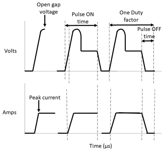
Figure 6.
Representation of EDM parameters on voltage–current waveform profile.
2.3.1. Gap Voltage and Discharge Voltage
Gap voltage is defined as the voltage in the gap between both electrodes. The voltage at which electrical sparks occur between the electrode tool and workpiece is termed as the discharge voltage, and its value relies upon the spark gap as well as the dielectric breakdown strength [105]. When the electrodes are subjected to an open gap voltage, an ionization path is established throughout the dielectric, and it increases the flow of current [106]. As the current flows, the voltage drops and then get stabilized at the level of the working gap. This voltage gives the spark gap width between the workpiece and the tool electrode. An increase in this voltage results in an improved flushing and stable discharge process. Gill and Kumar [12] discovered that increasing the discharge voltage leads to increasing the surface roughness, TWR, MRR, and microhardness, as an increasing voltage triggers the spark growth or discharge energy. Therefore, the higher strength of the electric field, achieved by raising the open-circuit voltage, results in a better material removal rate (MRR), tool wear rate (TWR), and roughness [107]. On the other hand, when the voltage is set at a low level, the discharge energy conducted in the coating region is small. Further, the application of sintered electrodes leads to an improvement in the electrode material transfer towards the base material, and an increase in the weight of the workpiece is attained with the proper selection of the voltage [39,83]. Table 3 shows the summary of past literature work on the effect of the voltage during EDC.
Table 3.
The summary of past literature work on the effect of the voltage.
2.3.2. Peak Current and Average Current
The maximum current available per pulse from the power generator is known as the peak current. The average current is the average of the amperage in the spark gap measured over the pulse on time in a cycle [111]. During the EDC coating, the peak current assists in initiating the electrical spark to reach up to the spark temperature that is required to deposit the tool material on the parent material [112]. Thus, optimum value of current is needed to transfer the maximum material to achieve a denser and more uniform coating [113].
Gill and Kumar [12] discovered that a large value of peak current leads to poor surface roughness. When the peak current increases, the discharge energy increases, thereby increasing the surface roughness. At higher peak currents, as the spark intensity increases, more molten materials come out from the crater, resulting in a high surface roughness. Table 4 shows the summary of past literature work on the effect of peak current.
Table 4.
The summary of past literature work on the effect of peak current.
2.3.3. Pulse on and Pulse off Time
The on and off times per pulse for every cycle are stated in μs [107]. The rate of material removal is directly proportional to total energy enforced during the pulse on-time, which is governed by the on-time duration and peak amperage [107,111]. The pulse on-time and pulse off-time are called the pulse duration and pulse interval, respectively. The time duration for which the peak current flows through the tool electrodes is known as the pulse on-time. It is denoted by Ton. The erosion process mainly depends upon the Ton value. Toff is the duration when there is no current flowing through the electrode, and unwanted debris particles between the electrodes are flushed away. It should be mentioned that there are two important parameters in the pulse current method: the pulse frequency and duty cycle. Pulse frequency is obtained from the formula 1/(Ton + Toff), while the duty factor is calculated by the following formula [107]:
Duty Factor (%) = Ton/(Ton + Toff) × 100
As time increases, the current flow across the electrode increases [113]. At a high value of Ton, the development of a microcrack and voids bounding the craters is observed, which is generally due to the effect of the rise in energy into the substrate surface. Additionally, the rapid cooling along with differential thermal contraction tends to disrupt the coating and crack generation [82]. During the pulse off-time, the dielectric is deionized and becomes an electrical insulator from a conductor. In EDC, both the dielectric deionization and cooling of the electrodes take place, which are required for the dispersion of spark discharges along the electrode surfaces to avoid erratic cycling. If the pulse off-time is too small, some portion of the material does not properly flush away by the dielectric, and the debris particles remain in discharge gap that causes a high probability of arcing [6]. The duty factor is designed as a thermodynamic and kinetic parameter because frequency affects the plasma density, which influences the processing rate. Therefore, when the duty factor is high, the coating becomes a thick layer. Hence, an increase in the duty factor is related to a thick coating layer [117]. Gill and Kumar [12] showed the effect of pulse on-time on roughness and claimed that the roughness improves with a low pulse on-time because a small spark area is produced at a low pulse on-time. Thereby, a small crater is generated on the workpiece and better roughness value is achieved. Table 5 shows the summary of the past literature work on the effect of the pulse on-time.
Table 5.
The summary of the past literature work on the effect of the pulse on-time.
2.4. Analysis of Sparking, Arcing, and Short Circuit
In the EDM, the surface finish quality of base material is defined by the energy in each spark. Figure 7 represents the voltage and current waveforms showing different characteristics observed in the EDM process. In this process (with a static electrode), arc pulses are caused by an imperfect flushing of debris and result in the occurrence of continuous sparking on the same location, which could create a large and uneven crater size and significantly affect the surface quality. Additionally, in EDM, the high discharge temperature cracks the dielectric, causing the accumulation of carbon in the spark gap. The carbon formed will thus stick to the tool surface. The accumulated carbon and debris in the spark gap will lead to arcing and short circuits that degenerate the stable machining process. The formation of carbon elements during machining affects the normal discharge. It is essential to consider that debris accumulation leads to the enlargement in gap distance, which might result in a short circuit. Then, the short circuit pulse becomes more harmful as compared to the arc pulse. Hence, as soon as the arc pulse is detected, the pulse off-time is required to be extended to provide more time for flushing debris collected inside the spark gap and preventing debris accumulation [88].
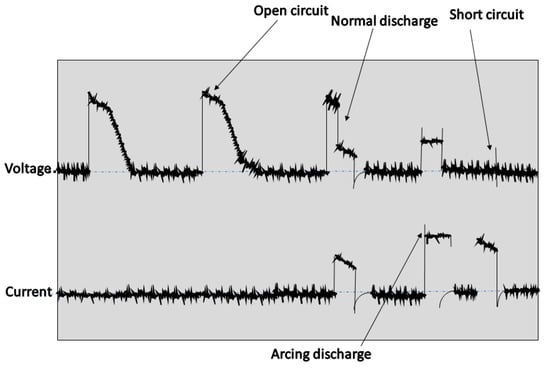
Figure 7.
Voltage and current waveforms for various types of pulses with a short circuit and open circuit [88].
The phenomenon of arcing during the EDC process has unfavorable effects on the quality of the coating. As it is obvious that there is no/light flushing used during the deposition process, debris particles therefore accumulate inside the working gap. At a high duty factor (short pulse off-time), the arcing becomes prominent, and this arcing phenomenon (continuous sparking) leads to the generation of a poor coating quality [6]. Thus, the imperfect flushing in electrical discharge coating needs further discussion and investigation in the EDC process.
3. Classification of the EDC Process
In the EDC process, the decomposed dielectric carbon particles react with tool electrode, and hard carbide is formed at a high temperature. This results in the formation of a thick hard layer over the workpiece [68]. From the principle of the EDC process, it can be inferred that the solid electrodes used in EDM are not suitable for coating because coating requires a compact mass of loose particles from which the material can be transferred over the workpiece. Many pioneer types of research in EDC report about the necessity of powder compact electrodes to perform the coating process in EDM. Additionally, the literature on coating through the electro discharge process suggests the use of suspended powders in the dielectric to fabricate a coating layer with hard as well as enhanced tribological properties. Therefore, this process can be classified into two categories, as discussed in the following subsections.
3.1. Green Compact Electrode Coating
The compact electrode is obtained by pressing of powders that are loosely bound with each other, and it is termed as a “green compact” electrode (Figure 8a). Before compaction, the mixing of powders is performed in a mortar for sufficient time to achieve uniform mixing. The prepared mixture of powders is placed in a hot mounting press, and the compressed mixture is kept for a certain heating and cooling time at the required pressure and temperature. It is stated that the green electrode is obtained by mixing one or more different metal powders with a soft metal powder as a bonding agent. The obtained green compact is fixed with a conductive metal rod, and it is used as a tool (Figure 8b) [6].
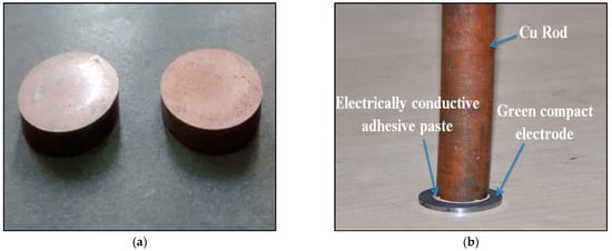
Figure 8.
(a) Green compact electrode and (b) tool electrode extension [6].
The green compact electrode used in EDC melts using electrical discharge process and deposits over the parent material. This necessary deposition is obtained due to weak bonding between the powder particles. The property of powders used for making the green compact tool electrode affects the coating characteristics. The powder size shows a significant effect on the quality of the coating, and the ranges of the used powders in the past literature are from approximately 1 to 175 µm. The surface roughness of the coating directly depends upon the size of the powder as it increases with coarser powder particles. Moreover, preparation of the compact tool is difficult with large-sized powders, whereas particles that are too small also exhibit a low sintering rate. The performance of tool electrodes made by powder metallurgy (P/M) is compared with conventional tool electrodes in EDM with straight polarity. It is found that the green compact electrode is more responsive to the pulse duration and current in comparison to a conventional solid electrode. The compact electrodes can result in the addition of material as compared to the removal of material, and the properties of the compact electrode can be controlled easily by changing the sintering and compaction parameters [74].
3.1.1. Parameters for the Preparation of Green Compact Electrode
Powder Composition
The composition of the powder is an important criterion for preparation of the tool electrode since it determines the coating properties, such as wear resistance, microhardness, surface roughness, etc. [121]. Besides, the mixture of two or more powders has a significant effect on the rate of material deposition and tool wear [117]. A binding powder is added in the green compact to improve the efficiency of the EDC process [122]. This binding powder material provides strength to the green compact and also helps in enhancing its conductivity when the other powder is less conductive [123]. Copper is used generally in the green compact electrode as it has a low melting temperature that assists in the rise of green compact tool wear rate and also allows for the incorporation of other high melting point materials [117]. In the past literature, the powder mixing ratio was varied at different levels according to the type of powder mixture, such as for lubricant, hBN, or WS2 with Cu in the ratio of 40:60 to 60:40, and similarly for hard coating W or WC with Cu at 30:70 to 70:30 [6,124]. However, the optimum proportion of copper is required while depositing the coating layer [117].
Compaction Pressure
The erosion of the electrode used in EDC is dependent upon the compaction pressure. It is the force applied per unit area upon the powdered particles during the preparation of a green compact electrode [4]. In this process, the appropriate compaction pressure is needed to obtain the required strength of the electrode [61]. For example, for easy material removal from the compact electrode, the particles are needed to be loosely compacted, so that they can be transferred onto the workpiece. On the other hand, if compact strength is increased substantially more than the certainty, the tool wear reduces, which also causes the deposition rate to decrease [39,125]. Therefore, an optimum level of pressure is to be maintained, such that the tool gets enough strength and the material is removed perfectly from a tool electrode in the process of electrical discharge coating [102].
Sintering Temperature
Sintering is another essential part in the preparation of a green compact electrode [126]. Due to certain conditions, the bonding shared between the green compact material particles of powder is not good, and the binding is not perfect. Thus, after compaction, sintering is carried out to improve the compact strength, and a certain sintering temperature is maintained. If this temperature goes beyond the powder melting point temperature, the powder properties change abruptly [127]. Thus, the heating temperature is maintained below the melting point. The compact becomes stronger at high sintering temperatures, whereas the sintered fully densified electrode might offer high electrical conductivity and hence result in continuous sparking. The material released will be limited, leading to low surface alloying [17,128]. Thus, the optimum sintering temperature is to be maintained such that the powders should not undergo melting, but the bonding of powder particles must be strong. The sintering temperature normally fluctuates between 130 °C and 13,000 °C for various materials.
3.1.2. Surface Coating Using Green Compact Electrodes
Surface modification using the powder metallurgy tool electrode is faster and less expensive. This method uses the green compact as a tool electrode to transfer loosely compact materials onto the substrate surface [89,106,124,129]. The powder green compact electrode is made under low-temperature and low-pressure conditions, and it exhibits some characteristics that are worthy for deposition, such as poor heat conduction, good resistance, high wearing speed, etc. The use of a green compact electrode to decrease the intensity of molecules along with low moldings pressure results in improved properties of EDC. Additionally, the sintered materials are easy to fabricate into all types of shaped electrodes. The smaller the powder diameter, the better the roughness of the hard layer. The materials used in electrodes comprise copper, tungsten, steel, brass, copper-ZrB2, chromium, copper-tungsten, and alloys [130,131,132,133]. Additionally, the existence of hard materials, such as W, WC, Ti, Cr, etc., in the electrode results in higher microhardness and better wear behavior of the coated surface [17,124,134,135]. When the surface of carbon steel and aluminum is engineered through EDC, remarkable changes are observed in the characteristics of the coated surface, exhibiting higher corrosion and wear resistance properties along with fewer cracks [63]. In this regard, the classified past research works on EDC using green compact electrode are discussed below.
Using Copper and Its Alloys in a Powder Compact Tool Electrode
Copper has a second highest electrical conductivity after silver, which makes it suitable in EDC in the form of a green compact electrode as silver is very costly. Copper is generally used as a binding material when the semiconducting or non-conductive powder coating is to be deposited. The conductivity of the whole green compact can be increased with the help of copper powder. Additionally, the increase in the composition of the main powder in the mixing ratio leads to a decrease in compactness of the tool electrode; hence, more material can be effectively deposited over the workpiece. Additionally, copper has a low melting point as compared to other powder, so its melting is faster and facilitates deposition of the green compact material efficiently [117]. The high corrosion resistance and low coefficient of friction of coppers and its alloys make it suitable to be used as a coating material. Similarly, a low coefficient of friction of bronze makes it desirable for coating over the surfaces. Hence, the use of a bronze compact electrode in EDC as a tool enhances the tool wear owing to its low binding energy. Gangadhar et al. (1991) studied the modified surface topology of mild steel when bronze compacts with 90% Cu and 10% Sn were used at reverse polarity in EDM. The X-ray diffraction plot revealed the formation of Cu3Sn, Cu6Sn5, Cu, and Sn. They reported the possibility of a change in metallurgical and chemical behavior of the mild steel due to the easier transportation of the tool material by the plasma. The physicochemical and metallurgical nature of the mild steel surface can be changed by appropriately changing the configuration of the powder compact. Those surfaces showed numerous craters, and comparatively big craters were observed over the bronze-coated surface. Using compact tools of bronze, the energy associated with an individual discharge was high as the spark took place through large asperities. Additionally, the low melting temperature and the high fluidity of melted bronze compared to those of the melted low carbon steel layer resulted in the large size of the crater [67]. Further, tools of high-speed steel processed with bronze compact were applied in cutting tests, and the tribological characteristics of the surface generated using a bronze compact tool in the electrical discharge process were studied. The bronze-deposited surface of mild steel resulted in a 15–30% drop of the friction coefficient. Drop-in cutting forces (10–25%) were observed during the cutting tests with bronze-coated high-speed steel (HSS) tools. However, the distribution of microhardness across the bronze-coated surface showed that the presence of a bronze layer led to low hardness [136]. Further, the chromium and copper particles also get transported from the chromium–copper-sintered tool electrodes connected at negative polarity. Subsequently, powders of Cu and Cr in the weakly bonded electrodes resulted in particle accumulation over the workpiece surface that increased its roughness [129]. Ho, et al. (2007) modified a Ti6-Al4-V surface with both compact and solid Cu electrodes using EDM in a water-based dielectric. The hardness of the recast layer improved from 3650.0025HK to 11000.0025HK. The glow discharge optical emission method was used to compare the tool material transfer to the workpiece surface for use of the solid electrode and compacted powder electrode. The results showed that 29% of Cu were transported from solid electrodes to the workpiece, whereas a transfer of Cu up to 78% was observed in the case of powder compact electrodes with 32 MPa pressed pellets [137].
Although copper and its alloys have a high melting point and excellent thermal and electrical conductivity, these studies show that the presence of copper and its alloys leads to a reduction in the overall hardness of the coating along with the surface roughness; therefore, other beneficial materials can be used for achieving various other desirable coating properties. Hence, researchers have used other combination of both hard and soft powder to impart desirable properties.
Using Copper/Silicon Carbide Powder Compact Tool Electrode
Being a hard material, SiC is widely employed in ceramic coating. The hardness, wear resistance, and abrasion resistance properties of SiC make it a popular choice in the application of coatings subjected to rigorous working conditions. The EDC process using straight polarity was performed with the help of a Cu-SiC green compact electrode. In this process, microhardness values 1.5–3 times higher than an Al-6351 alloy substrate and a coating layer thickness of maximum 83.644 μm were achieved successfully. In this study, the increment in the proportion of Cu compact pellets increased the bonding strength, which resulted in a lower rate of tool erosion and crater generation onto the surface of the Al-6351 alloy [138].
In this process, SiC gets decomposed into Si and C. As a result, a very small proportion of SiC gets deposited; hence, the improvement in surface hardness is comparatively less. Besides the lower surface roughness, the coating layer also showed a large amount of crater formations when the straight polarity was used. However, the negatively polarized green compact tool electrode could give better results. In this regard, the characterization of wear-resistant properties of the coated surface through reversed polarity for the Cu-SiC green compact is getting attention.
Using Tungsten/Tungsten Carbide Powder Compact Tool Electrode
The layer thickness and composition of the coating depend upon the electrical spark energy and the configuration of the parent material, green compact tool, and EDM oil. Hence, a deposition process of hard and wear-resistant coating over the parent material was attempted with the proper selection of material. To achieve this purpose, researchers attempted to transfer the coating of high hardness and enhanced surface roughness. Being a very hard material, tungsten carbide (WC) is extensively applied in the coating of cutting tools and industrial machinery applications. Further, the wear behavior of tungsten carbide is superior to tool steels. Researchers employed a compact electrode of 60% Fe and 40% WC to enhance the mild steel wear resistance. The EDS study of the coating ensured the formation of WC in the deposited coating layer along with other phases of WC and W2C as well as FeC, Fe3C, and Fe3C. As a result, enhancement in the abrasive wear resistance property was observed. A comparative analysis was reported between positively and negatively polarized electrodes with 70% Fe and 30% WC for machining 0.4% carbon steel. The white layer existence was also shown on machined work surfaces irrespective of the polarity being used. Apart from areas of tungsten-rich formation inside the alloyed white layer for the negative polarity, cracking and other surface defects were also present at high pulse energies during machining. For the given pulse energy, the negative polarity led to the formation of large single craters, while the positive polarity produced a more uniform and smoother surface [139]. Simao, et.al (2003) experimented to modify the surface of AISI H13 steel by using an electrode made of WC/Co powder, where Co was used as a bonding material. The parameters for the experiment were the peak current (1A to 3 A), machining time of 60 min, pulse on-time (20–40 µs), pulse off-time of 20 µs, and voltage (125–270 V). In this work, the electrode was sintered partially at a temperature of 1000 °C, which resulted in the formation of uniform coating. The average coating thickness obtained was 30 μm along with an enhancement in hardness from 640 HV to 1319 HV. It was seen that there was little effect of open gap voltage on the microhardness of the workpiece [66]. A similar experiment was carried out for the machining of steel (C-40 grade) using compact tool electrodes of WC/Cu. They captured the existence of both copper and WC over the workpiece surface, which was deposited for three minutes. They highlighted the major factors in the deposition process. A microstructure study showed comparatively fewer microcracks with microhardness increments (200–220 HV to 1200–1632 HV) [124]. The EDM alloying process on the aluminum surface using a W-Cu-Cr powder metallurgy electrode showed that the net mass transfer rate increased for a combination of W 65%, Cu 25%, and Cr 10%. The maximum value achieved for the mass transfer was 80.92 mg/min [140]. Chen, et al. (2008) showed the outcome of surface modifications by using a Cu-W powder semi-sintered electrode for the high peak current and no-load voltage. The material from the workpiece was removed for the low peak current and no-load voltage, and a deposit was also formed over the machined workpiece, which improved its performance [83].
Surface modification was performed using powder metallurgy 75% W–25% Cu-sintered EDM tools in which it was seen that the thin deposited layer on C40 plain carbon steel was finely distributed at a lower value of T Ton settings and was comparatively thick at a higher setting for peak current 10A and 8A, which resulted in consistent sparking and easy transportation of the tool material. A very thin layer was obtained by maintaining the sintering temperature at 700 °C, compaction pressure at 240 MPa, peak current at 8A, and pulse on-time at 38 μs; a very thick layer was obtained with the following process parameter settings: sintering temperature at 700 °C, compaction pressure at 120 MPa, peak current at 10A, and pulse on-time at 256 μs. The microhardness at the hardest region of a coated layer of a thickness 3–785 μm was 9.81–12.75 GPa, which was enriched with W and Cu particles along with tungsten carbide formation. Their study showed that the compact tool can be used for both machining and deposition by appropriately selecting the process parameters [126].
Although all the research work performed using W and WC powder in EDC illustrated the improvement in the overall hardness of the deposited coating layer, the WC formation resulted in a larger number of cracks forming owing to the high hardness along with the presence of hard reinforcing phases, such as carbides, which induced brittleness in the coating; thus, crack generation took place. The cracking reduced the mechanical properties and especially the fatigue limit of the component, which led to the adaption of different other hard powders. Hence, high pulse energies during coating must be avoided since they lead to extensive cracking and surface defects.
Using Titanium/Titanium Carbide Powder Compact Tool Electrode
Titanium is a ductile and soft metal that has a melting point of 1675 °C. Ti forms a chemically inert oxide film, which makes it corrosion resistant, even though TiC is an extremely hard ceramic metal similar to WC. Researchers reported on EDC coating over the surface of cutting tools, molds, and die in the presence of EDM oil through a green compact of TiC. The layer made by the semi-sintered TiC electrode has less defects. Additionally, the outcome of these experiments showed that its surface hardness is extremely high [141]. Similar research also showed the mold’s adherence was improved three times, and it became two times stronger than that of molds without coating. Life increased three to seven times. Additionally, the adhesive strength and tribological characteristics of these surfaces were enhanced [142]. Another study on aluminum surface modification was reported using titanium powder (64%) and aluminum powder (36%) compact electrodes. In this work, the titanium inside the electrode and carbon decomposed from the hydrocarbon resulted in the formation of TiC and TiA1 composite layers, and TiC with fine dendritic precipitates was obtained over the workpiece surface. In this regard, the hardness was achieved in the range of 3.5–10.5 GPa by changing the working time and pulse width. The morphology showed the formation of the pore was due to a combined effect of decomposed hydrogen from dielectric and rapid solidification. However, the generation of thermal stresses was reported, which were due to a change in a constituent of elemental distribution at a cross-section in the composite layers [143]. Kruth (1995) also proposed the process of the deposition of TiC over aluminum and aluminum over steel using Ti-Al and Al compact tool electrodes, respectively. During this experimentation concerning the formation of a white surface layer phenomenon in the presence of oil dielectric, the carbon content increased in the white layer and appeared in the form of Fe3C. In contrary to this, machining in the presence of water causing decarbonization was observed. It was also observed that negatively polarized porous electrodes favored the maximum tool wear rate [144]. EDC on carbon steel enhanced the microhardness and wear performance of carbon steel through the Ti green compact tool at negative polarity. The deposited coating thickness of up to 20 µm showed that the microhardness of the workpiece was increased from 332 HV to 2200 HV at the optimal setting of discharge current 4A and the discharge duration 8 µs. The reason for enhancement in this hardness is due to the carbide formation after the reaction of titanium with a carbon of the dielectric. In this regard, the presence of 51% TiC and 48% Fe in the coated surface was observed through X-ray diffraction analysis [74]. The TiC/Cu green compact tool was employed for the material transfer on the Al workpiece by this tool electrode, which resulted in an increase in microhardness from 155 HV to 1800 HV with a roughness of 8.12 µm and 51.24 mm layer thickness. The higher deposition and current value lead to a poor surface finish, whilst the lower value of the current provides smooth surface [145]. In EDC, titanium carbide (TiC) could be used to coat the graphite layer on the nickel workpiece with the help of a multi-layer electrode. The experimental results result in the formation of TiC due to a large amount of carbon from the graphite layer, which enhances the carbon concentration with an increase in the hardness of the coating [95].
EDC coating of titanium carbonitride (TiCN) on carbon steel was carried out, and a TiCN coating of 15 μm thickness with the presence of a TiC0.3N0.7 phase was obtained. The coefficient of friction and wear resistance to abrasion of the coated surface was found to be superior to the PVD TiN coating sample, as shown in Figure 9a,b. However, the TiCN surface was composed of a great number of stacked craters. The abrasive wear appeared in the PVD TiN coating as the applied load exceeded 30 N, whilst the TiCN coating showed better wear resistance. The maximum microhardness of PVD TiN coating (HV0.2 1980) was slightly higher as compared to the TiCN coating (HV0.2 1780) [146].
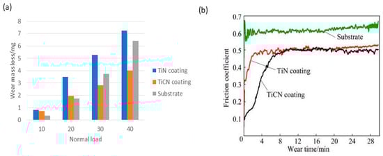
Figure 9.
(a) Wear mass loss and (b) coefficients of friction vs. wear time curve for coatings and substrate [146].
A tribological study of ED coating deposited through a semi-sintered electrode over the SS304 and HSS substrate was conducted. The coating that was achieved on HSS was more wear resistant (two to four times) than SS304, but it also depended on the loading conditions and substrate type (Figure 10). The variation of the wear rate was also due to many factors, such as the morphology of the cermet coatings combined with the mechanical properties of the substrate. Additionally, laser processing of the TiC/Fe electrical discharge coating deposited onto the SS304 and HSS substrate at 240 W and 280 W power completely homogenized the coating by eliminating the microcracks and pores of the as-polished surface formed during EDC, as shown in Figure 11. Still, laser processing resulted in a rise in the wear rate except for with HSS under high loads [7].
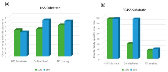
Figure 10.
Wear rate of substrates of: (a) HSS and (b) 304-SS (as polished substrate; EDM Cu machined surface; and ED-coated TiC/Fe cermet) [7].
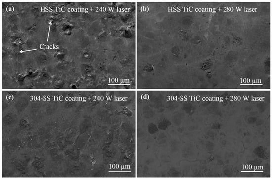
Figure 11.
SE images for laser-treated cermet coatings of TiC/Fe over the (a,b) HSS and (c,d) 304-SS, in terms of power [7].
Here, when the Ti percentage was high in the mixture of Ti/Cu, the electrode compactness decreased, such that the material of the tool electrode material was easily deposited over the workpiece. It was found that surface roughness was high with a larger amount of TiC in the electrode material because more overlap craters form for large pulsed discharge values, making a fluctuant-coated surface that needs to be interrogated. On the other hand, the multi-layer electrode reduced the surface roughness of the coating; however, the coated layer inhomogeneity was due to different electrode wear for each material. The micropore and crack formations can be removed through the EDC process using a sacrificial electrode of TiC along with Si. Hence, apart from improvement in microhardness and wear resistance, it is necessary to further reduce the frictional coefficient of the coating for lower friction losses in the matting parts of a machine component. However, the use of solid lubricant particles in EDC can exceptionally improve the frictional and wear behavior of the coated surface.
Using a Solid Lubricant Powder Compact Tool Electrode
Solid lubrication is an effective way to enhance the tribological behavior in a demanding service situation because the machinery parts work in a vacuum/at the high-temperature environment when the normal grease and lubricating oil could not work effectively. Strong adhesion is required among the workpiece and coating to enhance the service life of any part that can be achieved by good mixing of a solid lubricant with the workpiece. In this regard, EDC can be an acceptable process for coating a variety of materials using solid lubricants, which are used in many industrial applications or to enhance the wear and friction. Various solid lubricant materials can work in EDC to achieve this purpose, i.e., tungsten disulfide, molybdenum disulfide, graphite, hexagonal boron nitride, etc. [147]. A solid lubricant WS2 coating was obtained to fabricate the lubricant surfaces on the parent material (mild steel) through ED coating in the presence of dielectric hydrocarbon oil. The green compact of Cu and WS2 powder with a different mixing ratio of powder (WS2: Cu/40:60, 50:50, 60:40) was prepared. ED coating was deposited using die sink EDM at various peak current values (4A, 7A, and 10A) and duty factor values (30%, 50%, 70%, and 90%) at a constant pulse on-time (29 µs) and voltage (40 V) for 4 min of machining time. The morphology of the coating prepared at the 7A peak current showed least pores for WS2: Cu/60:40 as shown in Figure 12. The friction and wear behavior of the coating were analyzed at each duty cycle and current values in which the best value of the wear and friction coefficient was obtained at 60:40 and 7A peak current, due to maximum amount of WS2 in the mixing ratio with the best microstructure at the 7A peak current. Solid lubricant surfaces showed the minimum value of wear was 6.71 micro with 44.11 HV of microhardness at a 2 kg load (Figure 13) [6].
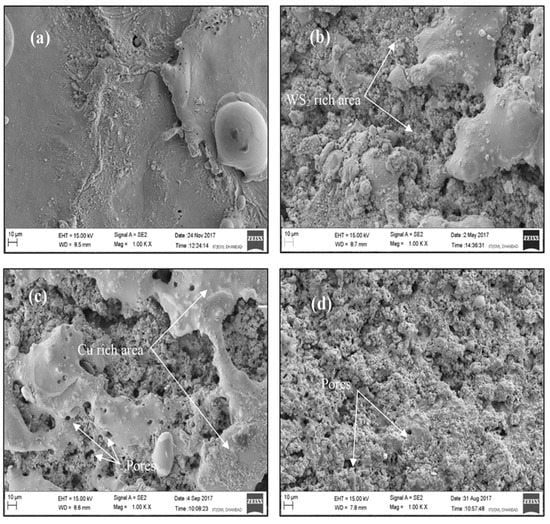
Figure 12.
FESEM images of coating prepared at WS2:Cu (a) 0:100, (b) 40:60, (c) 50:50, and (d) WS2:Cu/60:40 [6].
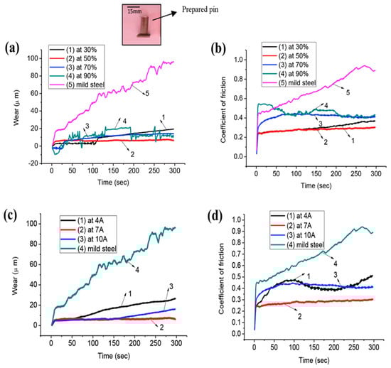
Figure 13.
(a,c) Wear and (b,d) coefficient of friction performance of coated surface [6].
In recent research work, the lubricating coating was also fabricated over mild steel substrate by using powders of hBN and Cu for making compact electrodes and used as an EDM tool. The effect on morphology, tribological performance, and hardness of the hBN−Cu coating layer were discussed. FESEM images ensured fewer pores in the coating prepared at hBN: Cu/50:50, 10 A current, and 70% duty factor. Due to soft lubricant nature of hBN, the microhardness drastically reduced up to 75.76 HV. Moreover, the tribological behavior outcome showed the lubrication nature of hBN, indicating a large drop in the friction coefficient along with wear resistance [117]. Similarly, the MoS2 + Cu coating was fabricated onto the mild steel, which also showed enhancement in tribological properties [102]. Hence, solid lubricant deposition through EDC was found to be the simplest emerging process of coating.
The tribological behavior of the coating showed excellent behavior in both wear and friction terms, although some drawbacks include pore formation and quite a low hardness that needs to be improved in the solid lubricant coating. Table 6 shows the summary of the past literature work on EDC with green compact electrodes.
Table 6.
The summary of past literature work.
Using Multi-Layer Electrode
Researchers have tried to use multi-layer green compact electrodes where different materials can be used in different layers, as shown in Figure 14 [95], as per the requirement. In this regard, Hwang, et al. (2010) proposed EDC with a multi-layer electrode to coat the titanium carbide layer on the surface of a nickel workpiece. The multi-layer electrode (MLE) is composed of titanium (Ti) and graphite (Gr) layers. The results obtained using both MLE and mixed powder green compact were compared. It was reported that the MLE for this powder combination produced better results in terms of microhardness, surface roughness, microcracks, and wear abrasion resistance [95]. These outcomes were consistent with reported results of Murray, et al. (2016). Further studies claimed that the coating layers can be produced on the complex surfaces [148,149].
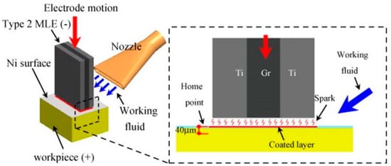
Figure 14.
Schematic of TiC layer over the Ni workpiece by multi-layer electrode [95].
With the help of EDC, a TiC coating was developed to eliminate the defects by incorporation of silicon debris. EDX maps in Figure 15a shows the Ti was present throughout the coating, as shown in SEM, though its distribution was not completely consistent. These different bulk structures were due to variation in the corrosion regime during the etching process. The wear resistance of both single and multi-layer coatings of TiC over stainless steel was evaluated with the assistance of ball-on-flat wear testing, which showed the best results of wear regardless of cracking left in the TiC single layer coating. The surface cracks were eliminated and worse friction was produced in a double coating of TiC + Si in comparison to TiC. The coating of TiC + Si resulted in zero porosity and negligible surface cracks, as illustrated in Figure 15b. The cross-sectional images of the TiC + Si double-layer show that cracking was completely removed as the lower melting point of Si than TiC, which resulted in the removal of the majority of the Si as it reaches the workpiece surface, owing to the explosive effect of discharge that prevents penetration inside the coating layer [148]. Recently, the mechanism of TiC coating that eliminates the defects by incorporation of Si debris was explained. Figure 16 shows the mechanism involved in improving the coating layer defect when Si as an electrode was used at the end of the coating. These low-density Si particles served in enhancing the gap width, as Si enhances the uniformity and density distribution of its particles between the spark gaps. Due to this, bubble expansion became slower when there was a smaller gap. The process of resolidification and expulsion of the material becomes less intense; therefore, the composite coating layer has fewer cracks and pores with low surface roughness. Hence, the attenuation process of spark discharge through gap widening by Si debris resulted in excellent layer properties. They concluded that these coatings can be generated on components with complex surfaces [149]. Table 7 shows the summary of the past literature work on EDC with a multi-layer electrode.
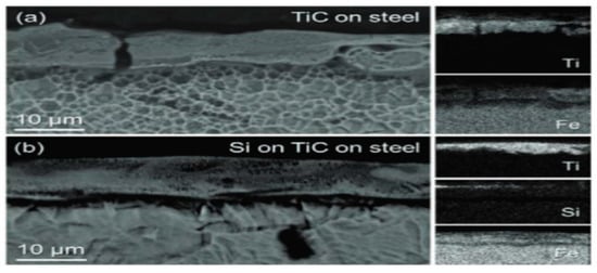
Figure 15.
Images of coating cross-sectional showing BSE and EDX maps of (a) TiC layer and (b) TiC + Si coating layer [148].
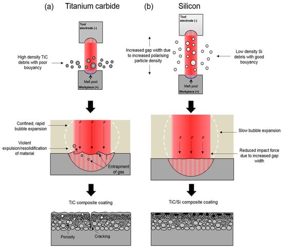
Figure 16.
Schematic of mechanism involved in defect-free coating [149].
Table 7.
Summary of the past literature work on EDC with a multi-layer electrode.
3.2. Powder Mixed Dielectric Coating
The coating action was also examined when the metal powder was added inside the dielectric fluid by the addition of various metal powders, including graphite, nickel, chromium, and silicon, into the dielectric to enhance the workpiece surface characteristics, such as resistance to wear, microhardness, and corrosion. By using conductive powders, the spark gap distance can be enlarged along with improvement in the surface due to reduction in spark energy and the more random dispersion of discharges all over the surface [151]. The solid electrode is also used to deposit different combinations of materials for the deposition process.
3.2.1. Surface Coating Using a Suspension of Powder/Gas in Dielectric
By mixing the powder in the working dielectric, the green compact electrode preparation process can be excluded in EDC, and the desired surface coating is obtained over the workpiece [152]. The spark generation between the workpiece and the electrode causes some reaction between the mixed powder and carbon particles, due to which a layer of necessary material is obtained over the workpiece [153]. Figure 17 shows the schematic of powder mixed EDC, which is sometimes also termed as electrical discharge alloying [78]. The particles of powder suspended in hydrocarbon oil assist in the ignition by enhancing the probability of higher discharge and reducing the insulating hydrocarbon oil breakdown strength, and hence, the sparking efficiency is enhanced. Additionally, the increase in microhardness of the coated layer is observed as the powder concentration changes [154,155].
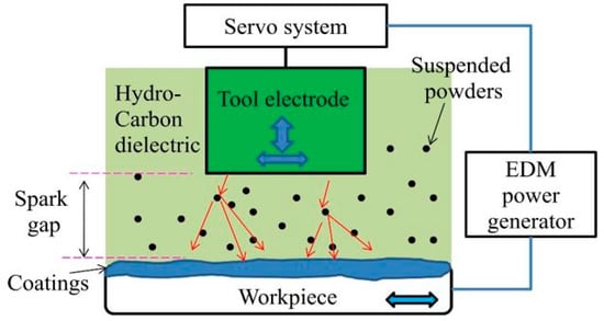
Figure 17.
Schematic of powder mixed EDC [78].
The Suspension of Solid Lubricant
The solid lubricant layer over the stainless steel and carbon steel is obtained by suspending molybdenum disulfide powder in dielectric fluid when short pulse duration, high open-circuit voltage, low discharge current, and moderate pulse interval are used to fabricate components required for ultrahigh vacuum applications. Some drawbacks were found with the process, including the difficulty in confirming that the powder is maintained in suspension process [156]. The powder settling issue in EDM was solved by surfactant addition along with powder particles inside the dielectric fluid. It was seen that surface roughness was improved to 0.2 μm owing to an improvement in discharge distribution [157]. Further, the EDC process also adopted the process of the powder mixed dielectric to deposit the coating material. Previously, the EDC process was employed to apply titanium carbide (TiC) on the 45-carbon steel surface by using a titanium powder-sintered electrode as the tool along with EDM oil with both graphite-mixed (GM) powder as well as a powder without graphite (WG). The machined surface had a higher value of hardness (1360–1420 HV0.05) with the GM TiC coating due to the additional carbon. Similarly, the friction coefficient in GM coating reduced from 0.13 to 0.1 under the 20 N and 50 N load, respectively, due to formation of the lubricated surface at the contact area with the deposition of amorphous carbon from graphite [78]. The powder mixed EDM coating was performed on AISI H13 tool steel substrate by varying the discharge current and processing time along with MoS2 particle size from 2 µm to 15 µm, which was suspended within the dielectric. Molybdenum particles with particle size < 15 μm at 10A current showed a uniform coated layer free from pores and microcracks with a thickness of 5 μm and 14 GPa hardness. Microhardness of the resolidified layer improved four times due to the presence of Mo in the solid solution along with various phases of Mo, such as Fe-Mo and MoxC, which were investigated from EDX and XRD analyses [158].
Hence, the solid lubricant powder suspension along with powder-sintered electrode is found to be helpful in achieving better hardness and tribological properties as compared to other different materials [159]. MoS2 can be decomposed into other compounds due to spark heat, and MoS2 gets deposited over the metals with a lower melting point than MoS2. The irregular concentration of MoS2 causes the dispersion of lubricant duration. The extension of gap length causes better roughness. However, few surface defect formations were observed, and further investigation should be performed using other different powder combinations.
The Suspension of Titanium Powder
The use of conductive powders (aluminum, graphite and semiconductive silicon powders) is suggested to obtain a mirror-like finish over the SKH-54 substrate. Although aluminum powder was unsuccessful in achieving a target, silicon powder and graphite powder provided a mirror-like finish. It was concluded that the negative polarity of the electrode was essential to attain the mirror finish [160]. Many experiments were carried out with chromium, aluminum, silicon carbide, and copper powders in which it was observed that aluminum provided the finest surface finish on the SKD-11 work surface followed by chromium [104]. The worst surface features were produced by the copper.
After seeing the flow of the dielectric inside the EDM, the application of a rotating disk and thin electrode were expected to maintain a high powder concentration between the spark gap and accrete of powder over the workpiece. Accretion machining was used at different electrical conditions. The Ti powder was suspended in kerosene to prepare the TiC layer of a thickness of 150 mm with high hardness (1600 HV) on carbon steel by using a 1 mm diameter electrode. When a disk was kept closed to a plate that rotates inside a viscous liquid, the disk started dragging the liquid in the gap in between the plate and disk. In this way, the powder concentration in the discharge gap was kept high, and a broader region of accretion was achieved with the help of gear shape rotary electrode [161]. The tungsten carbide surface was modified in the presence of dielectric oil mixed with titanium powder. By using this tungsten carbide in the presence of dielectric oil mixed with titanium powder, the variation in duty cycles and current resulted in a variation in the coated layer thickness. The sparking procedure inside a dielectric allowed for workpiece wear through the heat of the reaction, which led to workpiece melting (Figure 18a). As the spark stopped, the workpiece surface returned into a cooling state and formed a layer (Figure 18b). This comprised a splattered layer and another layer that was removed during the spark process. The second layer was formed due to melting of material that was not removed and therefore named as a recast layer, and some heat-affected area was observed due to the melting and solidification process. This caused metal contamination onto the workpiece as a coating layer (Figure 18c). The prepared coating of TiC exhibited high hardness (1750 HV) without generating microcracks [114].
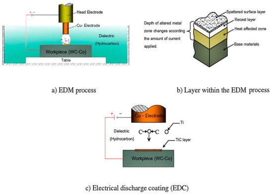
Figure 18.
(a) EDM process and (b) layer within EDM and (c) EDC [114].
The SEM images of the machined surface, as shown in Figure 19, prepared by EDC and conventional EDM illustrate that the density of the microcrack obtained by EDM was greater and longer as compared to those achieved through EDC. Furthermore, recast layers over the machined workpiece showed a complete removal of cracks in EDC. In this work, the surface obtained by EDC was better and smoother than the surface achieved through EDM. Figure 18a represents the experimental set-up for the experimentation. It can be seen in Figure 18b that there are three layers, which consist of a base metal, heat-affected region, and a recast layer. This contained contaminated metallic particles due to the dielectric environment and the existence of carbon disintegrated from the hydrocarbon oil. Additionally, the formation of TiC increases the microhardness of the coated layer without the formation of microcracks, as shown in Figure 18c [114].
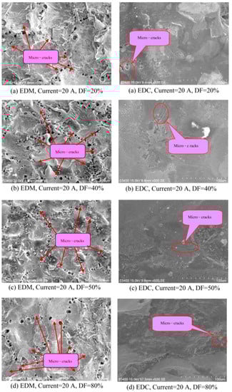
Figure 19.
SEM images of the surface prepared by EDC and conventional EDM [114].
Using Hydroxy-Apatite (HA) Mixed Dielectric
Ou, et al. (2016) described a method to modify the surface of titanium alloy by electrical discharge coating (EDC). In this work, a hydroxy-apatite (HA) coating was prepared over a 70Ti–30Ta alloy by using EDC followed by hydrothermal treatment. They used HA powder with distilled water as a dielectric medium. They showed that the coated surface was comprised of Ti and Ta oxides and contained P and Ca, and the coating thickness of approximately 7 μm was deposited with a roughness of Ra 2 μm. They reported that, after hydrothermal treatment at 150 °C, the incorporated P and Ca got precipitated to form petal-like HA crystals over the coating, and the coating showed hydrophilic tendencies. In this way, the surface treatment highly enhanced the wettability of the Ti–Ta alloy surfaces [162]. However, no significant change in roughness was obtained before hydrothermal treatment.
Quarry Dust Suspension
To improve the surface finish by EDC, quarry dust is utilized, which is an environmental waste formed by crushing the stones to acquire concrete aggregates. Recently, Ching, et al. (2020) modified the tungsten carbide cobalt (WC-Co) surface by using the different concentrations of waste quarry dust as a material of coating in EDC process. Figure 20 shows the EDC set-up for quarry dust suspension. The improvement in hardness and surface finish with negligible microcracks and micropores was observed at a dust concentration of 10 g/L [121]. It is clearly seen that the coating layer thickness increased with the increment of the current and pulse interval (Figure 21) [163]. However, a few micrometer thicknesses were obtained, and this process can be only used for thin coating preparation. These results proved the ability of reusing quarry dust as an eco-friendly coating material in the surface modification process. Table 8 shows the summary of past literature work on EDC with powder mixed additive.
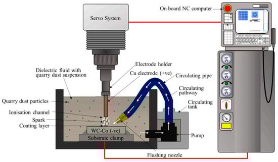
Figure 20.
The EDC set-up for quarry dust suspension [163].
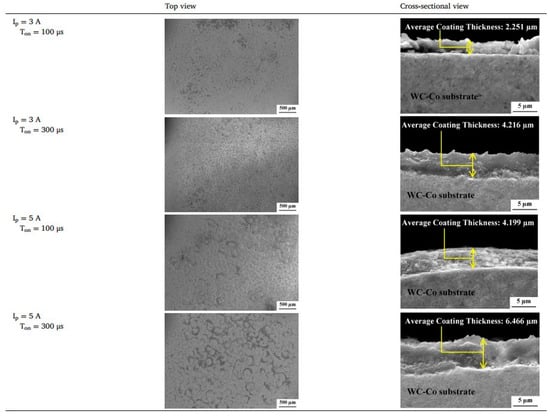
Figure 21.
Top and cross-section view of coating [163].
Table 8.
Summary of past literature work on EDC with powder mixed additive.
The powder suspension method using TiN led to better results as compared to the compact electrode technique; hence, further research was then performed using other different suspended powders in a dielectric.
Using Dry EDC Process
Dry EDC is a newly developed technology that needs either gas or a combination of fluid (water or oil) and gas in the dielectric liquid. This process helps to reduce the cost of oil- or liquid-based dielectric fluid. In addition, the environmental pollution can be overcome through the dry EDC process by preventing this process from forming any type of byproduct, which assists in avoiding human health hazards. In this direction, Chen, et al. (2013) deposited a TiN ceramic coating by using dry EDC in which high discharge energy resulted in a coarser layer along with presence of a weak phase of Ti2N and slight AlN phase (Figure 22). Additionally, the presence of a few voids was also observed owing to uneven coverage and cracks formed as a result of a mismatch of thermal expansion between the Al and TiN matrix. Additionally, TiN grains adhered over the Al alloy as a result of insufficient energy. Considering EDC, the optimum selection of discharge parameters could allow for Ti particles to react with N2, and at that time, a TiN film can homogeneously be deposited over the Al alloy [166]. In this work on dry EDC, the tribological behavior of the coating was missing. Meanwhile, it also contained a few voids in the film due to incomplete coverage, and microcracks resulted from the thermal expansion mismatch between TiN and the Al matrix.
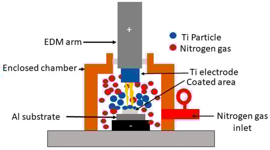
Figure 22.
Dry EDC process [166].
4. Applications of Surface Modified by EDC
There are various surface-coating technologies used currently, including electroplating, laser cladding, physical vapor deposition, and plasma spraying [9]. However, EDC is yet not widely employed by industries, even though many studies have highlighted its functions in different sectors and applications, as shown in Figure 23. EDC has a large range of applications in both the automotive and manufacturing industry. In the manufacturing field, surface modification through EDC is employed in electrical discharge texturing or roll texturing. In addition, it is extensively used in automotive industries in reducing the wear of aluminum and its alloys used in the aerospace and automobile industries [96]. Surface alteration is also applied successfully in a tool, die, and mold manufacturing industry; turbine blades making; automotive industry; and in other many industrial applications [167]. On the other hand, it can be applied in a coating on cutting tools to enhance its cutting performance and life, aa well as the surface alloying of dies, molds, and machining parts [168]. These applications are discussed in detailed below.
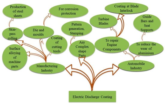
Figure 23.
Recent applications of EDC.
4.1. In Roll Surface Texturing
Roll texturing is also named as the electric discharge texturing (EDT) process, which is one of the EDC applications. Roll texturing was used to deposit a hard particle of compact tool (Ti/W/Cr) onto the roll surface due to the electrical spark formed between a compact tool and roll. The industrial temper mill work rolls are one of the examples of roll texturing where the concept of EDC is employed. EDT is carried out by shot blasting and cross-grinding. It was observed that higher concentrations of W and Ti get deposited at the roll surface. The microhardness was due to the presence of hard carbides of W and FeC. The process of texturing of Sendzimir rolls through electrical discharge is also applied for the production of steel sheets. The hardness of the workpiece increases with improvement in its performance and the life cycle of the roll in roll texturing [8]. The electrical discharge coating was also employed with TiC-sintered tool to analyze the microhardness, coating thickness, surface roughness, and wear performance of the coated layer deposited on the roll surface. It was desirable for the better service life of the roll for industrial applications for consistent control of the surface texture. The method of skin-pass rolling was used for the evaluation of steel sheet surface texture by maintaining the roll surface topography. The effect on the clarity of coating and formability of the sheet press was studied. A hard layer was formed by EDC with a TiC electrode, which showed a Vickers hardness of greater than HV1500 and controllable surface roughness. The wear of coated rolls generated was greater than chrome-plated rolls [92]. Further, EDC was applied on A2 steel and over the temper mill roll by using the cemented tungsten carbide electrode as shown in Figure 24 [169].
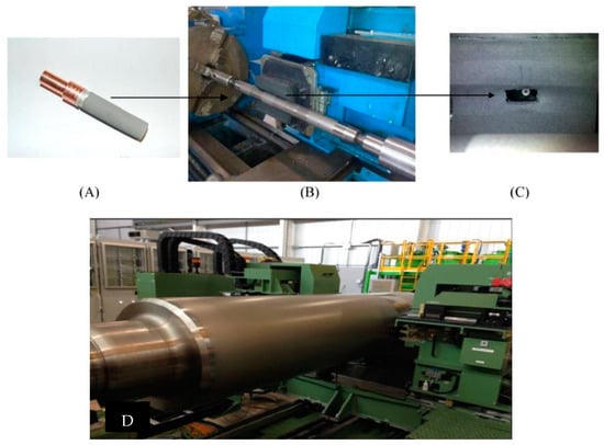
Figure 24.
(A–C) EDC surface bands on A2 steel and (D) EDC over temper mill roll [169].
4.2. To Repair the Turbine Blade
Thick EDC, which is known as “MS coating”, is applied to repair components. Conventionally, in the repair process of airplane engines, surface modification or cladding methods, such as plating, welding, or metal spray, are used. As an example of application of microspark coating, the sample is used in the low pressure turbine (LPT) blade interlock of the airplane engine [21,23].
4.3. Pattern Generation and Stamping
By using reverse EDM and by changing the process parameters, it is possible to produce the complex-shaped pattern [170,171]. Recently, a green compact tool was used to generate a predefined pattern by depositing its constituent materials [172]. EDC is also known as “MS coating” by which marks of two companies are stamped. It can be observed that even the edges of marks can be stamped clearly without masking [21,23].
4.4. In Guide Bars, Seat Supports/Bearing Plates
The metal weight and its quality have an important role in aerospace industries. Aluminum and its alloys have attracted attention in the automotive industry owing to the high specific strength and lightweight properties such that it can replaced steel. There is a variety of applications of aluminum alloys that have been used in the automotive industry to improve the tribological performance of [173]. Aluminum and its alloys suffer erosion due to the effect of airborne particles; hence, a coating is an effective way to overcome its erosion. To provide these qualities, EDC becomes an effective technique in terms of the coating.
4.5. In Die and Mould Coating
Other various vital industrial applications include manufacturing of mold, die, and turbine blades to prevent the defects as shown in Figure 25 [174,175]. EDC provides a hard and corrosion-resistant layer without changing the properties of the original material, which has broadened its application in die, tools, molds, turbine blades, etc. as they erode due to corrosion. Researchers reported that the life of molds and cutting tools can be enhanced by applying EDC coating using a Ti or TiC electrode [141,142,176].
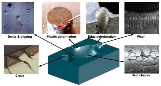
Figure 25.
Defects in die and molds [174,175].
4.6. In the Biomedical Field
The application of EDM has also been extended up to orthopedic implants due to involvement of a new technology in which dielectric fluids are mixed with certain additives i.e., powders of metal, surfactant, and different types of gases. It comprises mixing the liquid dielectric with some additives, for example, surfactant, metal powders, oxygen, and nitrogen gasses, which have extended the applications of EDM. Apart from enhancing the resistance to wear and corrosion, the mixing of additives has immensely helped in enhancing the mechanical properties and fatigue life of orthopedic implants [177,178]. Further, the applications of additive mixed process help to prepare the biocompatible and nanoporous coating film over the machined implant surface [115,179]. Figure 26 shows the artificial hip joint and corrosion occurred after implantation [180,181]. In summary, the EDC has an excellent contribution to modify the material surface and functionalization for biomedical applications [178,182,183,184]. With the help of EDC process, the biocompatibility of artificial implants can be upgraded by the cells’ attachment and proliferation [185,186].
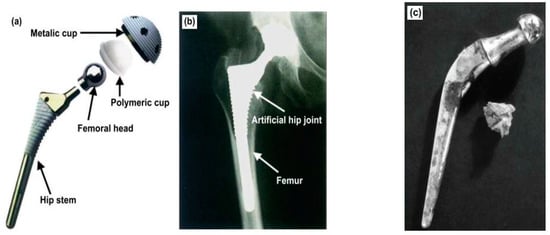
Figure 26.
Artificial hip joint: (a) structure, (b) implanted into human body, and (c) corrosion after implantation [180,181].
5. Challenges in the EDC and Future Scope
As the components with superior tribological properties are in high demand for industrial applications, EDC has emerged as a promising coating technology. Its tool electrode material, electrode size, process parameters, and type of dielectrics can directly affect the surface integrity of the workpiece. However, the pasdt literature of EDC is limited to certain materials and effects of this process on other materials like aluminum, and its alloys are unexplored. Additionally, investigations of the solid lubricant coating through EDC is a major research gap. Further, the following issues need to be focused on for achieving a desired electrical discharge coating:
- A major drawback in EDC process is that the position of tool electrode and workpiece should be parallel, which influences the uniformity in the coating.
- The phenomenon results in accretion in which a new layer formation and material removal occur together, which needs to be identifiable. Hence, the tool wear should be increased as compared to the cutting speed of the base material.
- Despite the minimization of defects in EDC as compared to EDM, the surface roughness of the coating gets compromised, which needs to be improved.
- The circulation of liquid dielectric and debris removal are general problems in coating, which restrict the efficiency of the coating process.
- There is no/light flushing used in ED process; hence, arcing is the major issue in EDC that deteriorates the surface finish and restricts the proper deposition, which leads to an unstable coating process.
- Degradation of surface roughness in EDC is observed for an improper composite powder mixing duration in mortar and for using dielectric oil with a random selection of process parameters.
6. Conclusions
Past literature on research of EDC has manifested its feasibility and necessary improvements in the surface characteristics. However, this technique is still in the experimental stage, and many more problems need to be resolved before the method can be adopted by any industry. In this regard, the following general conclusions can be drawn:
- The process of surface coating by means of green compact electrodes and the powder suspension EDC method proposed is a good option in place of other costlier techniques of surface coating like laser cladding, thermal spraying, electroless plating, etc. In EDC, the current and pulse on-time in EDC is identified as a major effective parameter in the EDC process.
- The green compact tool prepared with hard powders (TiC and WC) showed high hardness and more defects, and the coating with soft powders (WS2, MoS2 and hbn) showed low hardness with less defects. Therefore, researchers have suggested both hard and soft powder in the green compact tool to impart desirable properties.
- By mixing the powder in the working dielectric, the green compact electrode preparation process can be excluded in EDC. By preparing a hydroxy-apatite (HA) coating by powder mixed EDC, hydrophilic properties can be achieved. Further, the TiC powder mixed coating also showed high hardness, but the presence of defects needs to be reduced.
- The multi-layer electrode was also used in EDC, and researchers have tried to use multi-layer green compact electrodes to reduce the defects in TiC coatings. However, a low recast layer thickness was obtained by using this type of electrode, which cannot be used for complex-shaped parts.
- Among all these processes, the dry EDC process proved to be the best alternative to reduce the environmental pollution. In this study, the tribological behavior of the coating was missing, and the coating also contained a few voids in the film due to incomplete coverage and microcracks.
- From an application point of view, EDC has a large range of applications in both the automotive and manufacturing industries. The application has also been extended to orthopedic implants for enhancement of wear and corrosion resistance, mechanical properties, and fatigue life. Further, the process can also be applied in biomedical applications.
Author Contributions
Conceptualization, R.T.; supervision, A.M. and R.C.; visualization, A.K.D. and A.T.; writing—original draft, R.T.; writing—review & editing, C.P. and K.K.S. All authors have read and agreed to the published version of the manuscript.
Funding
This research received no external funding.
Conflicts of Interest
The authors declare no conflict of interest.
References
- Khadem, M.; Penkov, O.V.; Yang, H.K.; Kim, D.E. Tribology of Multilayer Coatings for Wear Reduction: A Review. Friction 2017, 5, 248–262. [Google Scholar] [CrossRef]
- Hogmark, S.; Jacobson, S.; Larsson, M. Design and Evaluation of Tribological Coatings. Wear 2000, 246, 20–33. [Google Scholar] [CrossRef]
- Arun, I.; Yuvaraj, C.; Selvarani, P.; Senthilkumaar, J.S.; Thamizhmanii, S.; Muruganandam, P. Synthesis of Electrical Discharge Metal Matrix Composite Coating through Compacted Semi-Sintered Electrode and Its Tribological Studies. J. Braz. Soc. Mech. Sci. Eng. 2019, 41, 213. [Google Scholar] [CrossRef]
- Sheng, C.; He, G.; Hu, Z.; Chou, C.; Shi, J.; Li, J.; Meng, Q.; Ning, X.; Wang, L.; Ning, F. Yarn on Yarn Abrasion Failure Mechanism of Ultrahigh Molecular Weight Polyethylene Fiber. J. Eng. Fibers Fabr. 2021, 16, 1–9. [Google Scholar] [CrossRef]
- Liew, P.J.; Yap, C.Y.; Nurlishafiqa, Z.; Othman, I.S.; Chang, S.Y.; Toibah, A.R.; Wang, J. Material Deposition on Aluminium by Electrical Discharge Coating (Edc) with a Tungsten Powder Suspension. J. Adv. Manuf. Technol. 2018, 12, 133–145. [Google Scholar]
- Tyagi, R.; Das, A.K.; Mandal, A. Electrical Discharge Coating Using WS2 and Cu Powder Mixture for Solid Lubrication and Enhanced Tribological Performance. Tribol. Int. 2018, 120, 80–92. [Google Scholar] [CrossRef]
- Algodi, S.J.; Murray, J.W.; Brown, P.D.; Clare, A.T. Wear Performance of TiC/Fe Cermet Electrical Discharge Coatings. Wear 2018, 402–403, 109–123. [Google Scholar] [CrossRef]
- Elkoca, O. A Study on the Characteristics of Electrical Discharge Textured Skin Pass Mill Work Roll. Surf. Coat. Technol. 2008, 202, 2765–2774. [Google Scholar] [CrossRef]
- Prakash, C.; Kansal, H.K.; Pabla, B.S.; Puri, S. Effect of surface nano-porosities fabricated by powder mixed electric discharge machining on bone-implant interface: An experimental and finite element study. Nanosci. Nanotechnol. Lett. 2016, 8, 815–826. [Google Scholar] [CrossRef]
- Ning, F.; He, G.; Sheng, C.; He, H.; Wang, J.; Zhou, R.; Ning, X. Yarn on Yarn Abrasion Performance of High Modulus Polyethylene Fiber Improved by Graphene/Polyurethane Composites Coating. J. Eng. Fibers Fabr. 2021, 16, 1–10. [Google Scholar] [CrossRef]
- Huang, H.; Huang, M.; Zhang, W.; Pospisil, S.; Wu, A.T. Experimental Investigation on Rehabilitation of Corroded RC Columns with BSP and HPFL under Combined Loadings. J. Struct. Eng. 2020, 146, 8. [Google Scholar] [CrossRef]
- Pramanik, A.; Basak, A.; Prakash, C. Understanding the wire electrical discharge machining of Ti6Al4V alloy. Heliyon 2019, 5, e01473. [Google Scholar] [CrossRef] [PubMed]
- Mughal, M.P.; Farooq, M.U.; Mumtaz, J.; Mia, M.; Shareef, M.; Javed, M.; Jamil, M.; Pruncu, C.I. Surface Modification for Osseointegration of Ti6Al4V ELI Using Powder Mixed Sinking EDM. J. Mech. Behav. Biomed. Mater. 2021, 113, 104145. [Google Scholar] [CrossRef] [PubMed]
- Balanou, M.; Karmiris-Obratański, P.; Leszczyńska-Madej, B.; Papazoglou, E.L.; Markopoulos, A.P. Investigation of surface modification of 60CrMoV18-5 steel by EDM with Cu-ZrO2 powder metallurgy green compact electrode. Machines 2021, 9, 268. [Google Scholar] [CrossRef]
- Murray, J.W.; Algodi, S.J.; Fay, M.W.; Brown, P.D.; Clare, A.T. Formation Mechanism of Electrical Discharge TiC-Fe Composite Coatings. J. Mater. Process. Technol. 2017, 243, 143–151. [Google Scholar] [CrossRef]
- Machkale, P.D.; Dabade, B.M. Experimental Investigation of Tungsten and Copper Carbide Coating on AISI 1020 Steel Using Electro Discharge Coating Process. Mater. Today Proc. 2020, 26, 2915–2920. [Google Scholar] [CrossRef]
- Patowari, P.K.; Saha, P.; Mishra, P.K. Artificial Neural Network Model in Surface Modification by EDM Using Tungsten-Copper Powder Metallurgy Sintered Electrodes. Int. J. Adv. Manuf. Technol. 2010, 51, 627–638. [Google Scholar] [CrossRef]
- Ahmed, A. Deposition and Analysis of Composite Coating on Aluminum Using Ti-B 4C Powder Metallurgy Tools in EDM. Mater. Manuf. Process. 2016, 31, 467–474. [Google Scholar] [CrossRef]
- Matsukawa, K.; Satoh, K.; Goto, A.; Saito, N.; Mohri, N. Wear Properties of Surface Modified Hard Layers Using Electrical Discharge Machine. J. Adv. Mech. Des. Syst. Manuf. 2008, 2, 629–639. [Google Scholar] [CrossRef]
- Spadło, S.; Młynarczyk, P. Influence of the of Electrical Discharge Alloying Methods on the Surface Quality of Carbon Steel. Int. J. Adv. Manuf. Technol. 2017, 89, 1529–1534. [Google Scholar] [CrossRef]
- Ahmed, N.; Murray, J.W.; Yuzawa, T.; Nakagawa, T.; Sarugaku, S.; Saito, D.; Brown, P.D.; Clare, A.T. Formation of Thick Electrical Discharge Coatings. J. Mater. Process. Technol. 2020, 285, 116801. [Google Scholar] [CrossRef]
- Ahmed, N.; Murray, J.W.; Yuzawa, T.; Kurokawa, T.; Nakagawa, T.; Sarugaku, S.; Saito, D.; Clare, A.T. Residual Stress in Electrical Discharge Coatings. Surf. Coat. Technol. 2021, 416, 127156. [Google Scholar] [CrossRef]
- Goto, A.; Akiyoshi, M.; Ochiai, H.; Watanabe, M. Development of Micro Spark Coating. In Proceedings of the 24th International Congress of the Aeronautical Sciences, Yokohama, Japan, 29 August–3 September 2004; pp. 1–7. Available online: https://www.semanticscholar.org/paper/DEVELOPMENT-OF-MICRO-SPARK-COATING-Goto-Akiyoshi/0e4e5f31907babf4a7517bb160ba70b725736377 (accessed on 31 July 2022).
- Nakano, Y.; Araki, T.; Yamada, A.; Teramoto, H.; Okane, M.; Goto, A. Development of Innovative Coating Technology, MSCoating, Using Electrical Discharge. In Proceedings of the Turbo Expo: Power for Land, Sea, and Air, Glasgow, UK, 14–18 June 2010; Volume 43963, pp. 929–937. [Google Scholar]
- Dong, H.; Bell, T. State-of-the-Art Overview: Ion Beam Surface Modification of Polymers towards Improving Tribological Properties. Surf. Coat. Technol. 1999, 111, 29–40. [Google Scholar] [CrossRef]
- Lee, Y.; Han, S.; Lim, H.; Kim, Y.; Kim, H. Surface Analysis of Polymers Electrically Improved by Plasma-Source Ion-Implantation. Anal. Bioanal. Chem. 2002, 373, 595–600. [Google Scholar] [CrossRef] [PubMed]
- Jagatheeshwaran, M.S.; Elayaperumal, A.; Arulvel, S. Wear Characteristics of Electroless NiP/Bio-Composite Coatings on En8 Steel. J. Manuf. Process. 2015, 20, 206–214. [Google Scholar] [CrossRef]
- Rajput, M.S.; Pandey, P.M.; Jha, S. Modelling of High Speed Selective Jet Electrodeposition Process. J. Manuf. Process. 2015, 17, 98–107. [Google Scholar] [CrossRef]
- Wu, Z. Empirical Modeling for Processing Parameters’ Effects on Coating Properties in Plasma Spraying Process. J. Manuf. Process. 2015, 19, 1–13. [Google Scholar] [CrossRef]
- Wang, G.; Huang, Z.; Xiao, P.; Zhu, X. Spraying of Fe-Based Amorphous Coating with High Corrosion Resistance by HVAF. J. Manuf. Process. 2016, 22, 34–38. [Google Scholar] [CrossRef]
- Ando, T.; Nishitani-Gamo, M.; Rawles, R.E.; Yamamoto, K.; Kamo, M.; Sato, Y. Chemical Modification of Diamond Surfaces Using a Chlorinated Surface as an Intermediate State. Diam. Relat. Mater. 1996, 5, 1136–1142. [Google Scholar] [CrossRef]
- Fuke, I.; Prabhu, V.; Baek, S. Computational Model for Predicting Coating Thickness in Electron Beam Physical Vapor Deposition. J. Manuf. Process. 2005, 7, 140–152. [Google Scholar] [CrossRef]
- De Damborenea, J. Surface Modification of Metals by High Power Lasers. Surf. Coat. Technol. 1998, 100–101, 377–382. [Google Scholar] [CrossRef]
- Zhang, P.R.; Liu, Z.Q.; Guo, Y.B. Machinability for Dry Turning of Laser Cladded Parts with Conventional vs. Wiper Insert. J. Manuf. Process. 2017, 28, 494–499. [Google Scholar] [CrossRef]
- Dini, J.W. Properties of Coatings: Comparisons of Electroplated, Physical Vapor Deposited, Chemical Vapor Deposited, and Plasma Sprayed Coatings. Mater. Manuf. Process. 1997, 12, 437–472. [Google Scholar] [CrossRef]
- Legg, K.O.; Graham, M.; Chang, P.; Rastagar, F.; Gonzales, A.; Sartwell, B. The Replacement of Electroplating. Surf. Coat. Technol. 1996, 81, 99–105. [Google Scholar] [CrossRef]
- Pawlowski, L. The Science and Engineering of Thermal Spray Coatings; John Wiley & Sons: Hoboken, NJ, USA, 2008. [Google Scholar]
- Madhaw, S. Surface Modification by Electro-Discharge Coating with WC-Cu P/M Electrode Tool. Bachelor’s Thesis, National Institute of Technology, Rourkela, India, 2013. [Google Scholar]
- Krishna, M.E.; Patowari, P.K. Parametric Optimisation of Electric Discharge Coating Process with Powder Metallurgy Tools Using Taguchi Analysis. Surf. Eng. 2013, 29, 703–711. [Google Scholar] [CrossRef]
- Bhushan, B. Principles and Applications of Tribology; John Wiley & Sons: Hoboken, NJ, USA, 1999. [Google Scholar]
- ASM. ASM Handbook, Volume 18: Friction, Lubrication, and Wear Technology; ASM International: Almere, The Netherlands, 1992. [Google Scholar]
- Holmberg, K.; Erdemir, A. The Impact of Tribology on Energy Use and CO2 Emission Globally and in Combustion Engine and Electric Cars. Tribol. Int. 2019, 135, 389–396. [Google Scholar] [CrossRef]
- Sudagar, J.; Tamilarasan, R.; Sanjith, U.; Rajendran, R.; Kumar, R. Electroless Deposition of Nanolayered Metallic Coatings. In Nanoscaled Film and Layers; InTechOpen: London, UK, 2017; p. 27. [Google Scholar]
- Mallory, G.O.; Hajdu, J.B. Electroless Plating: Fundamentals and Applications; William Andrew: Norwich, NY, USA, 1990. [Google Scholar]
- Simko, M.; Silva, E.A.; Wolf, R.H.; Davis, S.P. Sheet Steel: Coated; Elsevier: Amsterdam, The Netherlands, 2001. [Google Scholar]
- Bhanvase, B.A.; Pawade, V.B.; Dhoble, S.J.; Sonawane, S.H.; Ashokkumar, M. Nanomaterials for Green Energy; Elsevier: Amsterdam, The Netherlands, 2018. [Google Scholar]
- Gunputh, U.; Le, H. Composite Coatings for Implants and Tissue Engineering Scaffolds. In Biomedical Composites; Elsevier: Amsterdam, The Netherlands, 2017; pp. 111–138. [Google Scholar]
- Shang, S.M.; Zeng, W. Conductive Nanofibres and Nanocoatings for Smart Textiles. In Multidisciplinary Know-How for Smart-Textiles Developers; Elsevier: Amsterdam, The Netherlands, 2013; pp. 92–128. [Google Scholar]
- Park, J.-H.; Sudarshan, T.S. Chemical Vapor Deposition; ASM International: Almere, The Netherlands, 2001; Volume 2. [Google Scholar]
- Beaux, M.F.; Vodnik, D.R.; Peterson, R.J.; Bennett, B.L.; Salazar, J.J.; Holesinger, T.G.; King, G.; Maloy, S.A.; Devlin, D.J.; Usov, I.O. Chemical Vapor Deposition of Mo Tubes for Fuel Cladding Applications. Surf. Coat. Technol. 2018, 337, 510–515. [Google Scholar] [CrossRef]
- Mattox, D.M. Handbook of Physical Vapor Deposition (PVD) Processing; William Andrew: Norwich, NY, USA, 2010. [Google Scholar]
- Mattox, D.M. Ion Plating. In ASM Handbook Volume 5: Surface Engineering; ASM International: Almere, The Netherlands, 1994. [Google Scholar]
- Fadavi, M.; Baboukani, A.R.; Edris, H.; Salehi, M. Study on High-Temperature Oxidation Behaviors of Plasma-Sprayed TiB 2-Co Composite Coatings. J. Korean Ceram. Soc. 2018, 55, 178–184. [Google Scholar] [CrossRef]
- Ivanova, A.A.; Surmeneva, M.A.; Shugurov, V.V.; Koval, N.N.; Shulepov, I.A.; Surmenev, R.A. Physico-Mechanical Properties of Ti-Zr Coatings Fabricated via Ion-Assisted Arc-Plasma Deposition. Vacuum 2018, 149, 129–133. [Google Scholar] [CrossRef]
- Toyserkani, E.; Khajepour, A.; Corbin, S.F. Laser Cladding; CRC Press: Boca Raton, FL, USA, 2004. [Google Scholar]
- Kumar, V.; Rakshit, R.; Das, A.K. Mechanical and Tribological Performance of Fiber Laser Cladded H-BN + SS316 Composite on SS316 Surface. J. Mater. Process. Technol. 2020, 278, 116509. [Google Scholar] [CrossRef]
- Baldridge, T.; Poling, G.; Foroozmehr, E.; Kovacevic, R.; Metz, T.; Kadekar, V.; Gupta, M.C. Laser Cladding of Inconel 690 on Inconel 600 Superalloy for Corrosion Protection in Nuclear Applications. Opt. Lasers Eng. 2013, 51, 180–184. [Google Scholar] [CrossRef]
- Kumar, S.; Mandal, A.; Das, A.K.; Dixit, A.R. Parametric Study and Characterization of AlN-Ni-Ti6Al4V Composite Cladding on Titanium Alloy. Surf. Coat. Technol. 2018, 349, 37–49. [Google Scholar] [CrossRef]
- Lu, Y.; Huang, G.; Wang, Y.; Li, H.; Qin, Z.; Lu, X. Crack-Free Fe-Based Amorphous Coating Synthesized by Laser Cladding. Mater. Lett. 2018, 210, 46–50. [Google Scholar] [CrossRef]
- Goto, A. Development of Electrical Discharge Coating Method. Proc. Int. Symp. Electro-Mach. 2001, 2, 581–588. [Google Scholar]
- Beri, N.; Maheshwari, S.; Sharma, C.; Kumar, A. Technological Advancement in Electrical Discharge Machining with Powder Metallurgy Processed Electrodes: A Review. Mater. Manuf. Process. 2010, 25, 1186–1197. [Google Scholar] [CrossRef]
- Samuel, M.P.; Philip, P.K. Power Metallurgy Tool Electrodes for Electrical Discharge Machining. Int. J. Mach. Tools Manuf. 1997, 37, 1625–1633. [Google Scholar] [CrossRef]
- Mohri, N.; Saito, N.; Tsunekawa, Y.; Kinoshita, N. Metal Surface Modification by Electrical Discharge Machining with Composite Electrode. CIRP Ann.-Manuf. Technol. 1993, 42, 219–222. [Google Scholar] [CrossRef]
- Mohri, N.; Fukusima, Y.; Fukuzawa, Y.; Tani, T.; Saito, N. Layer Generation Process on Work-Piece in Electrical Discharge Machining. CIRP Ann.-Manuf. Technol. 2003, 52, 157–160. [Google Scholar] [CrossRef]
- Hao, R.; Lu, Z.; Ding, H.; Chen, L. A Nonlinear Vibration Isolator Supported on a Flexible Plate: Analysis and Experiment. Nonlinear Dyn. 2022, 108, 941–958. [Google Scholar] [CrossRef]
- Li, X.; Yang, X.; Yi, D.; Liu, B.; Zhu, J.; Li, J.; Gao, C.; Wang, L. Effects of NbC Content on Microstructural Evolution and Mechanical Properties of Laser Cladded Fe50Mn30Co10Cr10-xNbC Composite Coatings. Intermetallics 2021, 138, 107309. [Google Scholar] [CrossRef]
- Li, X.; Yan, J.; Yu, T.; Zhang, B. Versatile Nonfluorinated Superhydrophobic Coating with Self-Cleaning, Anti-Fouling, Anti-Corrosion and Mechanical Stability. Colloids Surf. A Physicochem. Eng. Asp. 2022, 642, 128701. [Google Scholar] [CrossRef]
- Aspinwall, D.K.; Dewes, R.C.; Lee, H.G.; Simao, J. Electrical Discharge Surface Alloying of Ti and Fe Workpiece Materials Using Refractory Powder Compact Electrodes and Cu Wire. CIRP Ann.-Manuf. Technol. 2003, 52, 151–156. [Google Scholar] [CrossRef]
- Guan, X.; Wang, Y.; Zhang, G.; Jiang, X.; Wang, L.; Xue, Q. Microstructures and Properties of Zr/CrN Multilayer Coatings Fabricated by Multi-Arc Ion Plating. Tribol. Int. 2017, 106, 78–87. [Google Scholar] [CrossRef]
- Cui, G.; Han, B.; Zhao, J.; Li, M. Comparative Study on Tribological Properties of the Sulfurizing Layers on Fe, Ni and Co Based Laser Cladding Coatings. Tribol. Int. 2019, 134, 36–49. [Google Scholar] [CrossRef]
- Vuchkov, T.; Evaristo, M.; Yaqub, T.B.; Polcar, T.; Cavaleiro, A. Synthesis, Microstructure and Mechanical Properties of W–S–C Self-Lubricant Thin Films Deposited by Magnetron Sputtering. Tribol. Int. 2020, 150, 106363. [Google Scholar] [CrossRef]
- Thakur, A.; Gangopadhyay, S. Influence of Tribological Properties on the Performance of Uncoated, CVD and PVD Coated Tools in Machining of Incoloy 825. Tribol. Int. 2016, 102, 198–212. [Google Scholar] [CrossRef]
- Kumari, S.; Masanta, M. Ceramic-Metal Composite Coating on Steel Using a Powder Compact Tool Electrode by the Electro-Discharge Coating Process. Silicon 2018, 10, 1625–1637. [Google Scholar]
- Wang, Z.L.; Fang, Y.; Wu, P.N.; Zhao, W.S.; Cheng, K. Surface Modification Process by Electrical Discharge Machining with a Ti Powder Green Compact Electrode. J. Mater. Process. Technol. 2002, 129, 139–142. [Google Scholar] [CrossRef]
- Hatipoglu, G.; Kartal, M.; Uysal, M.; Cetinkaya, T.; Akbulut, H. The Effect of Sliding Speed on the Wear Behavior of Pulse Electro Co-Deposited Ni/MWCNT Nanocomposite Coatings. Tribol. Int. 2016, 98, 59–73. [Google Scholar] [CrossRef]
- Du, S.; Li, Z.; He, Z.; Ding, H.; Wang, X.; Zhang, Y. Effect of Temperature on the Friction and Wear Behavior of Electroless Ni–P–MoS2–CaF2 Self-Lubricating Composite Coatings. Tribol. Int. 2018, 128, 197–203. [Google Scholar] [CrossRef]
- Murray, J.W.; Ahmed, N.; Yuzawa, T.; Nakagawa, T.; Sarugaku, S.; Saito, D.; Clare, A.T. Dry-Sliding Wear and Hardness of Thick Electrical Discharge Coatings and Laser Clads. Tribol. Int. 2020, 150, 106392. [Google Scholar] [CrossRef]
- Xie, Z.J.; Mai, Y.J.; Lian, W.Q.; He, S.L.; Jie, X.H. Titanium Carbide Coating with Enhanced Tribological Properties Obtained by EDC Using Partially Sintered Titanium Electrodes and Graphite Powder Mixed Dielectric. Surf. Coat. Technol. 2016, 300, 50–57. [Google Scholar] [CrossRef]
- Liew, P.J.; Yap, C.Y.; Wang, J.; Zhou, T.; Yan, J. Surface Modification and Functionalization by Electrical Discharge Coating: A Comprehensive Review. Int. J. Extrem. Manuf. 2020, 2, 012004. [Google Scholar] [CrossRef]
- Shepeleva, L.; Medres, B.; Kaplan, W.D.; Bamberger, M.; Weisheit, A. Laser Cladding of Turbine Blades. Surf. Coat. Technol. 2000, 125, 45–48. [Google Scholar] [CrossRef]
- Sexton, L.; Lavin, S.; Byrne, G.; Kennedy, A. Laser Cladding of Aerospace Materials. J. Mater. Process. Technol. 2002, 122, 63–68. [Google Scholar]
- Algodi, S.J.; Murray, J.W.; Fay, M.W.; Clare, A.T.; Brown, P.D. Electrical Discharge Coating of Nanostructured TiC-Fe Cermets on 304 Stainless Steel. Surf. Coat. Technol. 2016, 307, 639–649. [Google Scholar] [CrossRef]
- Chen, Y.-F.; Chow, H.-M.; Lin, Y.-C.; Lin, C.-T. Surface Modification Using Semi-Sintered Electrodes on Electrical Discharge Machining. Int. J. Adv. Manuf. Technol. 2008, 36, 490–500. [Google Scholar] [CrossRef]
- Ho, K.H.; Newman, S.T. State of the Art Electrical Discharge Machining (EDM). Int. J. Mach. Tools Manuf. 2003, 43, 1287–1300. [Google Scholar] [CrossRef]
- Lazarenko, B.R. To Invert the Effect of Wear on Electric Power Contacts. Master’s Dissertation, All-Union Institute for Electro Technique, Moscow, Russian, 1943. [Google Scholar]
- Toren, M.; Zvirin, Y.; Winograd, Y. Melting and Evaporation Phenomena during Electrical Erosion. J. Heat Transfer. 1975, 97, 576–581. [Google Scholar] [CrossRef]
- Jameson, E.C. Electrical Discharge Machining: Tooling, Methods, and Applications; Society of Manufacturing Engineers: Southfield, MI, USA, 1983. [Google Scholar]
- Pey Tee, K.T.; Hosseinnezhad, R.; Brandt, M.; Mo, J. Pulse Discrimination for Electrical Discharge Machining with Rotating Electrode. Mach. Sci. Technol. 2013, 17, 292–311. [Google Scholar] [CrossRef]
- Jeswani, M.L. Effect of the Addition of Graphite Powder to Kerosene Used as the Dielectric Fluid in Electrical Discharge Machining. Wear 1981, 70, 133–139. [Google Scholar] [CrossRef]
- Tao, J.; Shih, A.J.; Ni, J. Experimental Study of the Dry and Near-Dry Electrical Discharge Milling Processes. J. Manuf. Sci. Eng. 2008, 130, 011002. [Google Scholar] [CrossRef]
- Mohri, N. Surface Modification by EDM-an Innovation in EDM with Semi-Conductive Electrodes. In Proceedings of the Winter annual meeting of the ASME, Chicago, IL, USA, 27 November 1988; Volume 34, pp. 21–31. [Google Scholar]
- Ueno, M.; Fujita, N.; Kimura, Y.; Nakata, N. Evaluation of Coating and Wear Characteristics of Roll Surface Coated with TiC by Electrical Discharge Coating. J. Mater. Process. Technol. 2016, 236, 9–15. [Google Scholar] [CrossRef]
- Mohri, N.; Fukuzawa, Y.; Tani, T.; Saito, N.; Furutani, K. Assisting Electrode Method for Machining Insulating Ceramics. CIRP Ann. 1996, 45, 201–204. [Google Scholar] [CrossRef]
- Kunieda, M.; Yoshida, M.; Taniguchi, N. Electrical Discharge Machining in Gas. CIRP Ann. 1997, 46, 143–146. [Google Scholar] [CrossRef]
- Hwang, Y.L.; Kuo, C.L.; Hwang, S.F. The Coating of TiC Layer on the Surface of Nickel by Electric Discharge Coating (EDC) with a Multi-Layer Electrode. J. Mater. Process. Technol. 2010, 210, 642–652. [Google Scholar] [CrossRef]
- Chen, H.J.; Wu, K.L.; Yan, B.H. Characteristics of Al Alloy Surface after EDC with Sintered Ti Electrode and TiN Powder Additive. Int. J. Adv. Manuf. Technol. 2014, 72, 319–332. [Google Scholar] [CrossRef]
- Kunieda, M.; Lauwers, B.; Rajurkar, K.P.; Schumacher, B.M. Advancing EDM through Fundamental Insight into the Process. CIRP Ann.-Manuf. Technol. 2005, 54, 64–87. [Google Scholar] [CrossRef]
- El-Hofy, H.A.-G. Fundamentals of Machining Processes: Conventional and Nonconventional Processes; CRC Press: Boca Raton, FL, USA, 2013. [Google Scholar]
- Zhang, Y.; Liu, Y.; Ji, R.; Cai, B. Study of the Recast Layer of a Surface Machined by Sinking Electrical Discharge Machining Using Water-in-Oil Emulsion as Dielectric. Appl. Surf. Sci. 2011, 257, 5989–5997. [Google Scholar] [CrossRef]
- Moro, T.; Mohri, N.; Otsubo, H.; Goto, A.; Saito, N. Study on the Surface Modification System with Electrical Discharge Machine in the Practical Usage. J. Mater. Process. Technol. 2004, 149, 65–70. [Google Scholar] [CrossRef]
- Yadav, A.; Mohanty, S.; Nag, A.; Dixit, A.R.; Das, A.K. A Concise Review on Improvement of Tribological Properties by Electrical Discharge Coating Process. AIP Conf. Proc. 2020, 2273, 50009. [Google Scholar]
- Zhong, Y.; Xie, J.; Chen, Y.; Yin, L.; He, P.; Lu, W. Microstructure and Mechanical Properties of Micro Laser Welding Nitinb/Ti6Al4V Dissimilar Alloys Lap Joints with Nickel Interlayer. Mater. Lett. 2022, 306, 130896. [Google Scholar] [CrossRef]
- Bernd, M. Schumacher. Efectividad de Biopreparados Cubanos de Producción Comercial En La Embriogénesis Somática de Papa. J. Mater. Process. Technol. 2004, 149, 376–381. [Google Scholar] [CrossRef]
- Yih-Fong, T.; Fu-Chen, C. Investigation into Some Surface Characteristics of Electrical Discharge Machined SKD-11 Using Powder-Suspension Dielectric Oil. J. Mater. Process. Technol. 2005, 170, 385–391. [Google Scholar] [CrossRef]
- Forster, E.O.; Yamashita, H.; Mazzetti, C.; Pompili, M.; Caroli, L.; Patrissi, S. The Effect of the Electrode Gap on the Breakdown Process in Liquid Dielectrics. In Proceedings of the 1993 IEEE 11th International Conference on Conduction and Breakdown in Dielectric Liquids (ICDL’93), Baden-Dattwil, Switzerland, 19–23 July 1993; pp. 383–389. [Google Scholar]
- Tyagi, R.; Pandey, K.; Mohanty, S.; Kumar, S.; Das, A.K.; Mandal, A. Optimization of Electrical Discharge Coating of WS 2 and Cu Powder Mixture Deposited Through Green Compact Electrode. In Advances in Industrial and Production Engineering; Springer: Berlin/Heidelberg, Germany, 2019; pp. 273–283. [Google Scholar]
- Kumar, S.; Singh, R.; Singh, T.P.; Sethi, B.L. Surface Modification by Electrical Discharge Machining: A Review. J. Mater. Process. Technol. 2009, 209, 3675–3687. [Google Scholar] [CrossRef]
- Prakash, V.; Shubham; Kumar, P.; Singh, P.K.; Das, A.K.; Chattopadhyaya, S.; Mandal, A.; Dixit, A.R. Surface Alloying of Miniature Components by Micro-Electrical Discharge Process. Mater. Manuf. Process. 2018, 33, 1051–1061. [Google Scholar] [CrossRef]
- Liew, P.J.; Yan, J.; Kuriyagawa, T. Experimental Investigation on Material Migration Phenomena in Micro-EDM of Reaction-Bonded Silicon Carbide. Appl. Surf. Sci. 2013, 276, 731–743. [Google Scholar] [CrossRef]
- Mansor, A.F.; Jamaluddin, R.; Azmi, A.I.; Lih, T.C.; Zain, M.Z.M. Surface Modification of Nitinol by Using Electrical Discharge Coatings in Deionized Water. IOP Conf. Ser. Mater. Sci. Eng. 2019, 670, 012010. [Google Scholar] [CrossRef]
- Davim, J.P. Microfabrication and Precision Engineering: Research and Development; Woodhead Publishing: Sawston, UK, 2017. [Google Scholar]
- Khan, M.Y.; Rao, P.S.; Pabla, B.S. A Framework for Surface Modification by Electrical Discharge Coating Using Variable Density Electrodes. E3S Web Conf. 2021, 309, 01093. [Google Scholar] [CrossRef]
- Maddu, J.; Karrolla, B.; Shaik, R.U.; Burdhuhos-Nergis, D.-P. SWOT Analysis of Electrical Discharge Coatings: A Case Study of Copper Coating on Titanium Alloy. Surfaces 2022, 5, 290–307. [Google Scholar] [CrossRef]
- Janmanee, P.; Muttamara, A. Surface Modification of Tungsten Carbide by Electrical Discharge Coating (EDC) Using a Titanium Powder Suspension. Appl. Surf. Sci. 2012, 258, 7255–7265. [Google Scholar] [CrossRef]
- Zou, R.; Yu, Z.; Li, W.; Guo, M.; Li, J. Influence of Porous Structure on the Machining Performance of Micro EDM. J. Mater. Process. Technol. 2016, 232, 43–51. [Google Scholar] [CrossRef]
- Prakash, C.; Uddin, M.S. Surface Modification of β-Phase Ti Implant by Hydroaxyapatite Mixed Electric Discharge Machining to Enhance the Corrosion Resistance and in-Vitro Bioactivity. Surf. Coat. Technol. 2017, 326, 134–145. [Google Scholar] [CrossRef]
- Tyagi, R.; Pandey, K.; Das, A.K.; Mandal, A. Deposition of HBN + Cu Layer through Electrical Discharge Process Using Green Compact Electrode. Mater. Manuf. Process. 2019, 34, 1035–1048. [Google Scholar] [CrossRef]
- Yap, C.Y.; Liew, P.J.; Wang, J. Surface Modification of Tungsten Carbide Cobalt by Electrical Discharge Coating with Quarry Dust Powder: An Optimisation Study. Mater. Res. Express 2020, 7, 106407. [Google Scholar] [CrossRef]
- Taylor, P.; Krishna, M.E.; Patowari, P.K. Materials and Manufacturing Processes Parametric Study of Electric Discharge Coating Using Powder Metallurgical Green Compact Electrodes Parametric Study of Electric Discharge Coating Using Powder Metallurgical Green Compact Electrodes. Mater. Manuf. Processes 2014, 29, 1131–1138. [Google Scholar] [CrossRef]
- Mussada, E.K.; Patowari, P.K. Post Processing of the Layer Deposited by Electric Discharge Coating. Mater. Manuf. Process. 2017, 32, 442–449. [Google Scholar] [CrossRef]
- Yap, C.Y.; Liew, P.J. Surface Modification of Tungsten Carbide Cobalt by Electrical Discharge Coating with Quarry Dust Suspension. Int. J. Adv. Manuf. Technol. 2020, 111, 2105–2116. [Google Scholar] [CrossRef]
- Tyagi, R.; Patel, V.S.; Das, A.K.; Mandal, A. Investigation on Electrical Discharge Coating of Brass and Copper Powder. Trans. Indian Inst. Met. 2022, 77, 1–10. [Google Scholar] [CrossRef]
- Tyagi, R.; Das, A.K.; Mandal, A. Wettability and Performance of Cu-MoS2/SiC Coating Prepared by Electro-Discharge Coating Process. Trans. Indian Inst. Met. 2022, 75, 1563–1572. [Google Scholar] [CrossRef]
- Patowari, P.K.; Mishra, U.K.; Saha, P.; Mishra, P.K. Surface Modification of C40 Steel Using WC-Cu P/M Green Compact Electrodes in EDM. Int. J. Manuf. Technol. Manag. 2010, 21, 83–98. [Google Scholar] [CrossRef]
- Liang, L.; Xu, M.; Chen, Y.; Zhang, T.; Tong, W.; Liu, H.; Li, H. Effect of Welding Thermal Treatment on the Microstructure and Mechanical Properties of Nickel-Based Superalloy Fabricated by Selective Laser Melting. Mater. Sci. Eng. A 2021, 819, 141507. [Google Scholar] [CrossRef]
- Patowari, P.K.; Saha, P.; Mishra, P.K. Taguchi Analysis of Surface Modification Technique Using W-Cu Powder Metallurgy Sintered Tools in EDM and Characterization of the Deposited Layer. Int. J. Adv. Manuf. Technol. 2011, 54, 593–604. [Google Scholar] [CrossRef]
- Tyagi, R.; Das, A.K.; Mandal, A. Tribology International Formation of Superhydrophobic Surface with Enhanced Hardness and Wear Resistance by Electrical Discharge Coating Process. Tribol. Int. 2021, 157, 106897. [Google Scholar] [CrossRef]
- Arun, I.; Duraiselvam, M.; Senthilkumar, V.; Narayanasamy, R.; Anandakrishnan, V. Synthesis of Electric Discharge Alloyed Nickel-Tungsten Coating on Tool Steel and Its Tribological Studies. Mater. Des. 2014, 63, 257–262. [Google Scholar] [CrossRef]
- Tsai, H.C.; Yan, B.H.; Huang, F.Y. EDM Performance of Cr/Cu-Based Composite Electrodes. Int. J. Mach. Tools Manuf. 2003, 43, 245–252. [Google Scholar] [CrossRef]
- Khanra, A.K.; Sarkar, B.R.; Bhattacharya, B.; Pathak, L.C.; Godkhindi, M.M. Performance of ZrB2-Cu Composite as an EDM Electrode. J. Mater. Process. Technol. 2007, 183, 122–126. [Google Scholar] [CrossRef]
- Guo, C.; Zhang, Z.; Wu, Y.; Wang, Y.; Ma, G.; Shi, J.; Zhong, J.; Hong, Z.; Jin, J.; Zhao, Y. Synergic Realization of Electrical Insulation and Mechanical Strength in Liquid Nitrogen for High-Temperature Superconducting Tapes with Ultra-Thin Acrylic Resin Coating. Supercond. Sci. Technol. 2022, 35, 075014. [Google Scholar] [CrossRef]
- Singh, S.; Maheshwari, S.; Pandey, P.C. Some Investigations into the Electric Discharge Machining of Hardened Tool Steel Using Different Electrode Materials. J. Mater. Process. Technol. 2004, 149, 272–277. [Google Scholar] [CrossRef]
- Singh, S.; Maheshwari, S.; Pandey, P.C. Experimental Investigations into Die-Sinking Electric Discharge Machining of Hardened AISI 6150 Tool Steel Using Different Electrode Materials. Stroj. Cas.-J. Mech. Eng. 2005, 56, 197–210. [Google Scholar]
- Beri, N.; Kumar, A.; Maheshwari, S.; Sharma, C. Optimisation of Electrical Discharge Machining Process with CuW Powder Metallurgy Electrode Using Grey Relation Theory. Int. J. Mach. Mach. Mater. 2011, 9, 103–115. [Google Scholar] [CrossRef]
- Föhl, J.; Weissenberg, T.; Wiedemeyer, J. General Aspects for Tribological Applications of Hard Particle Coatings. Wear 1989, 130, 275–288. [Google Scholar] [CrossRef]
- Shunmugam, M.S.; Philip, P.K.; Gangadhar, A. Tribological Behaviour of an Electrodischarge Machined Surface with a Powder Metallurgy Bronze Electrode. Tribol. Int. 1993, 26, 109–113. [Google Scholar] [CrossRef]
- Ho, S.K.; Aspinwall, D.K.; Voice, W. Use of Powder Metallurgy (PM) Compacted Electrodes for Electrical Discharge Surface Alloying/Modification of Ti-6Al-4V Alloy. J. Mater. Process. Technol. 2007, 191, 123–126. [Google Scholar] [CrossRef]
- Chakraborty, S.; Kar, S.; Dey, V.; Ghosh, S.K. Optimization and surface modification of al-6351 alloy using sic-cu green compact electrode by electro discharge coating process. Surf. Rev. Lett. 2017, 24, 1750007. [Google Scholar] [CrossRef]
- Pantelis, D.I.; Vaxevanidis, N.M.; Houndri, A.E.; Dumas, P.; Jeandin, M. Investigation into Application of Electrodischarge Machining as Steel Surface Modification Technique. Surf. Eng. 1998, 14, 55–61. [Google Scholar] [CrossRef]
- Das, S. Surface Alloying of Aluminium by W-Cu-Cr Powder Metallurgy Tool Electrode in EDM. Int. J. Latest Res. Eng. Technol. 2016, 2, 1–10. [Google Scholar]
- Moro, T.; Goto, A.; Mohri, N.; Saito, N.; Matsukawa, K.; Miyake, H. Surface Modification Process by Electrical Discharge Machining with TiC Semi-Sintered Electrode. J.-Jpn. Soc. Precis. Eng. 2001, 67, 114–119. [Google Scholar] [CrossRef]
- Miyake, H. Improvement of Tool Life through Surface Modification by Electrical Discharge Machining. Proc. ISEM 12 1998, 1405, 261–270. [Google Scholar]
- Tsunekawa, Y.; Okumiya, M.; Mohri, N.; Takahashi, I. Surface Modification of Aluminum by Electrical Discharge Alloying. Mater. Sci. Eng. A 1994, 174, 193–198. [Google Scholar] [CrossRef]
- Kruth, J.-P.; Stevens, L.; Froyen, L.; Lauwers, B. Study of the White Layer of a Surface Machined by Die-Sinking Electro-Discharge Machining. CIRP Ann. 1995, 44, 169–172. [Google Scholar] [CrossRef]
- Das, A.; Misra, J.P. Experimental Investigation on Surface Modification of Aluminum by Electric Discharge Coating Process Using TiC/Cu Green Compact Tool-Electrode. Mach. Sci. Technol. 2012, 16, 601–623. [Google Scholar] [CrossRef]
- Zeng, Z.Y.; Xiao, H.Q.; Jie, X.H.; Zhang, Y.M. Friction and Wear Behaviors of TiCN Coating Based on Electrical Discharge Coating. Trans. Nonferrous Met. Soc. China 2015, 25, 3716–3722. [Google Scholar] [CrossRef]
- Tyagi, R.; Das, A.K.; Mandal, A.; Saxena, K.K.; Tripathi, A. Hydrophobic Properties and Chemical State Analysis of Wear Resistant Coating Prepared by Electrical Discharge Process. Proc. Inst. Mech. Eng. Part E J. Process Mech. Eng. 2022, 0954408922109. [Google Scholar] [CrossRef]
- Murray, J.W.; Clare, A.T. Morphology and Wear Behaviour of Single and Multi-Layer Electrical Discharge Coatings. Procedia CIRP 2016, 42, 236–239. [Google Scholar] [CrossRef]
- Murray, J.W.; Cook, R.B.; Senin, N.; Algodi, S.J.; Clare, A.T. Defect-Free TiC/Si Multi-Layer Electrical Discharge Coatings. Mater. Des. 2018, 155, 352–365. [Google Scholar] [CrossRef]
- Priadi, D.; Siradj, E.S.; Winarto, W. Surface Modification of SKD 61 by Electrical Discharge Coating (EDM/EDC) with Multilayer Cylindrical Electrode and Jatropha Curcas as Dielectric Fluid. In Applied Mechanics and Materials; Trans Tech Publications Ltd.: Zurich, Switzerland, 2013; Volume 319, pp. 96–101. [Google Scholar]
- Kansal, H.K.; Singh, S.; Kumar, P. Parametric Optimization of Powder Mixed Electrical Discharge Machining by Response Surface Methodology. J. Mater. Process. Technol. 2005, 169, 427–436. [Google Scholar] [CrossRef]
- Mohanty, S.; Das, A.K.; Dixit, A.R. Surface Integrity of Tribo-Adaptive Layer Prepared on Ti6Al4V through μEDC Process. Surf. Coat. Technol. 2021, 429, 127922. [Google Scholar] [CrossRef]
- OGATA, I. Carburizing and Decarburazing Phenomena in EDM’d Surface. Int. J. Jpn. Soc. Prec. Eng. 1993, 27, 197–202. [Google Scholar]
- Kiran, P.; Mohanty, S.; Das, A.K. Surface Modification through Sustainable Micro-EDM Process Using Powder Mixed Bio-Dielectrics. Mater. Manuf. Process. 2021, 37, 640–651. [Google Scholar] [CrossRef]
- Okada, A. Formation of Hard Layer by EDM with Carbon Powder Mixed Fluid. In Proceedings of the 5th International Conference on Progress of Machining Technology, New Orleans, LA, USA, 9–12 January 2000; Volume 464, pp. 464–469. [Google Scholar]
- Furutani, K.; Shimizu, Y. Experimental Analysis of Deposition Process of Lubricant Surface by Electrical Discharge Machining with Molybdenum Disulfide Powder Suspended in Working Oil. In Proceedings of the 18th Annual Meeting of American Society for Precision Engineering, Portland, OR, USA, 26–31 October 2003; pp. 547–550. [Google Scholar]
- Wu, K.L.; Yan, B.H.; Huang, F.Y.; Chen, S.C. Improvement of Surface Finish on SKD Steel Using Electro-Discharge Machining with Aluminum and Surfactant Added Dielectric. Int. J. Mach. Tools Manuf. 2005, 45, 1195–1201. [Google Scholar] [CrossRef]
- Amorim, F.L.; Dalcin, V.A.; Soares, P.; Mendes, L.A. Surface Modification of Tool Steel by Electrical Discharge Machining with Molybdenum Powder Mixed in Dielectric Fluid. Int. J. Adv. Manuf. Technol. 2017, 91, 341–350. [Google Scholar] [CrossRef]
- Mohanty, S.; Kumar, V.; Das, A.K.; Dixit, A.R. Surface Modification of Ti-Alloy by Micro-Electrical Discharge Process Using Tungsten Disulphide Powder Suspension. J. Manuf. Process. 2019, 37, 28–41. [Google Scholar] [CrossRef]
- Wong, Y.S.; Lim, L.C.; Rahuman, I.; Tee, W.M. Near-Mirror-Finish Phenomenon in EDM Using Powder-Mixed Dielectric. J. Mater. Process. Technol. 1998, 79, 30–40. [Google Scholar] [CrossRef]
- Furutania, K.; Saneto, A.; Takezawa, H.; Mohri, N.; Miyake, H. Accretion of Titanium Carbide by Electrical Discharge Machining with Powder Suspended in Working Fluid. Precis. Eng. 2001, 25, 138–144. [Google Scholar] [CrossRef]
- Ou, S.F.; Wang, C.Y. Fabrication of a Hydroxyapatite-Containing Coating on Ti-Ta Alloy by Electrical Discharge Coating and Hydrothermal Treatment. Surf. Coat. Technol. 2016, 302, 238–243. [Google Scholar] [CrossRef]
- Yee, C.; Jun, P.; Sharhida, I.; Othman, B.; Fadzli, M.; Abdollah, B. Surface & Coatings Technology Tribological Characteristics of Electrical Discharge Coated Layers Using Quarry Dust Suspension. Surf. Coat. Technol. 2021, 428, 127895. [Google Scholar] [CrossRef]
- Li, S.L.; Mai, Y.J.; Huang, M.Y.; Jie, X.H. Anti-Wear Hierarchical TiC Enhanced Cermet Coating Obtained via Electrical Discharge Coating Using a Reduced Graphene Oxide Nanosheets Mixed Dielectric. Ceram. Int. 2020, 46, 11933–11942. [Google Scholar] [CrossRef]
- Mohanty, S.; Das, A.K.; Dixit, A.R. Surface Integrity and Residual Stress Analysis of μEDM Coated Ti-Alloy Miniature Components. Mater. Manuf. Process. 2021, 36, 48–58. [Google Scholar] [CrossRef]
- Chen, H.-J.; Wu, K.-L.; Yan, B.-H. Dry Electrical Discharge Coating Process on Aluminum by Using Titanium Powder Compact Electrode. Mater. Manuf. Process. 2013, 28, 1286–1293. [Google Scholar] [CrossRef]
- Lee, H.-T.; Yur, J.-P. Characteristic Analysis of EDMed Surfaces Using the Taguchi Approach. Mater. Manuf. Process. 2000, 15, 781–806. [Google Scholar] [CrossRef]
- Okada, M.; Yoshida, A.; Furumoto, T.; Watanabe, H.; Asakawa, N.; Otsu, M. Mechanisms and Characteristics of Direct Cutting of Tungsten Carbide Using a Diamond-Coated Carbide End Mill. Int. J. Adv. Manuf. Technol. 2016, 86, 1827–1839. [Google Scholar] [CrossRef]
- Bröcking, R.; Meghwal, A.; Melzer, S.; Verdier, S.; Evans, G.; Lowbridge, T.; Vanhumbeeck, J.F.; Debrabandere, D.; Crahay, J. Development of Electrical Discharge Coating (EDC) as Chrome-Free Alternative for Increasing Campaign Length of Temper Mill Work Rolls. Iron Steel Technol. 2015, 12, 68–76. [Google Scholar]
- Mazarbhuiya, R.M.; Dutta, H.; Debnath, K.; Rahang, M. Surface Modification of CFRP Composite Using Reverse-EDM Method. Surf. Interfaces 2020, 18, 100457. [Google Scholar] [CrossRef]
- Mazarbhuiya, R.M.; Rahang, M. PCM Assisted Reverse Electro Discharge Machining Process for Pattern Generation. Mater. Manuf. Process. 2021, 37, 995–1002. [Google Scholar] [CrossRef]
- Mazarbhuiya, R.M.; Rahang, M. Reverse EDM Process for Pattern Generation Using Powder Metallurgical Green Compact Tool. Mater. Manuf. Process. 2020, 35, 1741–1748. [Google Scholar] [CrossRef]
- Chen, W.C.; Lin, H.M.; Uan, J.Y. Formation and Characterization of Self-Lubricated Carbide Layer on AA6082 Al–Mg–Si Aluminum Alloy by Electrical Discharge Alloying Process. Trans. Nonferrous Met. Soc. China 2016, 26, 3205–3218. [Google Scholar] [CrossRef]
- Jhavar, S.; Paul, C.P.; Jain, N.K. Causes of Failure and Repairing Options for Dies and Molds: A Review. Eng. Fail. Anal. 2013, 34, 519–535. [Google Scholar] [CrossRef]
- Aliyu, A.A.; Abdul-Rani, A.M.; Ginta, T.L.; Prakash, C.; Axinte, E.; Razak, M.A.; Ali, S. A Review of Additive Mixed-Electric Discharge Machining: Current Status and Future Perspectives for Surface Modification of Biomedical Implants. Adv. Mater. Sci. Eng. 2017, 2017, 8723239. [Google Scholar] [CrossRef]
- Devarani, N.; Joshi, S.N. Electric Discharge Alloying of Titanium and Aluminium on AISI P20 Mold Steel. Surf. Coat. Technol. 2021, 405, 126515. [Google Scholar] [CrossRef]
- Mohammed, M.T.; Khan, Z.A.; Siddiquee, A.N. Surface Modifications of Titanium Materials for Developing Corrosion Behavior in Human Body Environment: A Review. Procedia Mater. Sci. 2014, 6, 1610–1618. [Google Scholar] [CrossRef]
- Kiran, P.; Mohanty, S.; Das, A.K. Sustainable Surface Modification of Ti-Alloy Using Powder Mixed in Bio-Dielectrics through Micro-Electrical Discharge Coating Process. J. Clean. Prod. 2022, 362, 132375. [Google Scholar]
- Peng, P.W.; Ou, K.L.; Lin, H.C.; Pan, Y.N.; Wang, C.H. Effect of Electrical-Discharging on Formation of Nanoporous Biocompatible Layer on Titanium. J. Alloys Compd. 2010, 492, 625–630. [Google Scholar] [CrossRef]
- Walczak, J.; Shahgaldi, F.; Heatley, F. In Vivo Corrosion of 316L Stainless-Steel Hip Implants: Morphology and Elemental Compositions of Corrosion Products. Biomaterials 1998, 19, 229–237. [Google Scholar] [CrossRef]
- Liu, X.; Chu, P.K.; Ding, C. Surface Modification of Titanium, Titanium Alloys, and Related Materials for Biomedical Applications. Mater. Sci. Eng. R Rep. 2004, 47, 49–121. [Google Scholar] [CrossRef]
- Wandra, R.; Prakash, C.; Singh, S. Investigation on Surface Roughness and Hardness of β-Ti Alloy by Ball Burnishing Assisted Electrical Discharge Cladding for Bio-Medical Applications. Mater. Today Proc. 2021, 50, 848–854. [Google Scholar] [CrossRef]
- Chen, S.-L.; Lin, M.-H.; Huang, G.-X.; Wang, C.-C. Research of the Recast Layer on Implant Surface Modified by Micro-Current Electrical Discharge Machining Using Deionized Water Mixed with Titanium Powder as Dielectric Solvent. Appl. Surf. Sci. 2014, 311, 47–53. [Google Scholar] [CrossRef]
- Sales, W.F.; Oliveira, A.R.F.; Raslan, A.A. Titanium Perovskite (CaTiO3) Formation in Ti6Al4V Alloy Using the Electrical Discharge Machining Process for Biomedical Applications. Surf. Coat. Technol. 2016, 307, 1011–1015. [Google Scholar] [CrossRef]
- Prakash, C.; Kansal, H.K.; Pabla, B.S.; Puri, S. Processing and Characterization of Novel Biomimetic Nanoporous Bio Surface on β-Ti Implant by Powder Mixed Electric Discharge Machining. J. Mater. Eng. Perform. 2015, 24, 3622–3633. [Google Scholar] [CrossRef]
- Yang, T.-S.; Huang, M.-S.; Wang, M.-S.; Lin, M.-H.; Tsai, M.-Y.; Wang, P.-Y.W. Effect of Electrical Discharging on Formation of Nanoporous Biocompatible Layer on Ti-6Al-4V Alloys. Implant Dent. 2013, 22, 374–379. [Google Scholar] [CrossRef] [PubMed]
Publisher’s Note: MDPI stays neutral with regard to jurisdictional claims in published maps and institutional affiliations. |
© 2022 by the authors. Licensee MDPI, Basel, Switzerland. This article is an open access article distributed under the terms and conditions of the Creative Commons Attribution (CC BY) license (https://creativecommons.org/licenses/by/4.0/).