Article

Analysis of the Electromagnetic Coupling Characteristics of Dual-Load Wireless Power Transmission Channels

1
Tianjin Key Laboratory of Intelligent Control of Electrical Equipment, Tiangong University, Xiqing District, Tianjin 300387, China
2
Department of Electrical Engineering, Tsinghua University, Haidian District, Beijing 100084, China
*
Author to whom correspondence should be addressed.
Processes 2022, 10(10), 1931; https://doi.org/10.3390/pr10101931
Submission received: 30 August 2022 / Revised: 15 September 2022 / Accepted: 17 September 2022 / Published: 24 September 2022

Abstract

:
This paper studies the characteristics of four dual-load systems, coaxial different sides, coaxial same side, different axis same side, and coplanar coaxial, based on the principle of near-field resonance wireless power transmission. Firstly, a dual-load cooperative coupling equivalent circuit model is established, the mathematical expression of system energy efficiency is derived, and the influence of the cross-coupling of the receiving coils in the system on the performance of the system is compared and analyzed in four coupling situations. Secondly, the magnetic field distribution characteristics and the influence of transmission distance and load impedance on the transmission characteristics are studied by electromagnetic field simulation software. Finally, the experimental results show that the maximum efficiency of the dual-load wireless power transmission system is only 0.43 in the case of coaxial and coplanar coupling, which is not suitable for power transmission. In the case of coaxial coupling on the same side, the received power of dual loads has a large difference, which is suitable for electrical equipment with different power requirements. When the coupling distance between the transmitting and receiving coils changes synchronously in the case of coaxial opposite-side and different axis same-side coupling, the efficiency of the former persisting declination and the efficiency of the latter rise first and then drop.

1. Introduction

Wireless power transmission technology provides a safe, reliable and flexible mode of power transmission for situations in which wired power supply is not suitable, is inconvenient, or is not allowed [1,2,3,4]. In 2007, magnetic coupling resonance wireless power transmission technology was proposed by the scientific research team of the Massachusetts Institute of Technology in the United States. The proposal of this technology has enabled wireless power transmission to achieve the major breakthrough in distance transmission. Based on the principle of magnetic coupling resonance wireless power transmission technology, domestic and foreign scholars have conducted extensive research work from multiple angles [5,6,7,8,9,10]. At present, some of the research results have been applied in the fields of low-power short-range wearable devices and smart phones. With the in-depth study of important scientific issues and key technologies of this topic, wireless transmission also shows broad potential application prospects in important fields such as transportation, industry, space, and submarine.
According to the existing literature, scholars at home and abroad have conducted in-depth studies on the characteristics of single-transmit-single-receive wireless power transmission systems from the perspectives of frequency splitting characteristics, coupling coil distribution parameters, and spatial magnetic field distribution [11,12,13]. However, there are scenarios where multiple loads, such as household appliances and portable electronic devices are charged at the same time. In the scenario where sensors are wirelessly charged in a wireless sensor network, the sensors are unevenly distributed in three-dimensional space, and the power levels and spatial locations are different. Therefore, to meet the practical application requirements of a single source transmitting power for multiple loads simultaneously, for multi-load wireless power transmission technology, the coupling mechanism of a multi-load wireless power transmission system was studied [14,15,16]. Cannon B.L, et al. [17] proposed a multi-load wireless power transmission system with different receiving coil structures and presented the corresponding circuit parameter design method but did not involve the single load receiving power control problem. Fu M.F, et al. [18] deduced the parameter relationship based on the dual-load case. Considering the coupling of two coils, the expressions of system power and efficiency are given, and the optimal operating conditions of the system are analyzed. Lee K, et al. [19] proposed adopting the impedance matching method to solve the power distribution problem in a multi-load system while ensuring the overall efficiency and stability of the system. In a study by Luo, et al. [20], a controllable resonant capacitor array is added at the transmitter. By selectively and periodically controlling the disconnection and access of each resonant capacitor, multiple loads have different natural resonant frequencies, so as to realize the stable power supply of the transmitter to different loads.
In summary, the current research data in the area of multi-load wireless power transmission does not consider the cross-coupling characteristics between coils and the impact on system performance under the different position distributions of multiple receiving coils. Therefore, this paper adopts dual-load wireless charging, which is common in actual application scenarios, as an example and conducts research on wireless charging systems with dual loads in different spatial positions. The research methods can be further promoted to provide guidance for multi-load wireless charging system scenarios.
In this paper, the four coupling situations of the coupling coils in the dual-load wireless power transmission system, coaxial opposite side, coaxial same side, different axis on the same side, and different axis coplanar, are studied. The main contributions of this paper are:
  • Through theoretical analysis, the influence of cross-coupling between the receiving coils of the system in different coupling situations is compared.
  • The electromagnetic field simulation software is used to analyze the transmission characteristics of the system when the coupling distance and load impedance of the transceiver end change, and the applicable working conditions under different coupling conditions are pointed out.
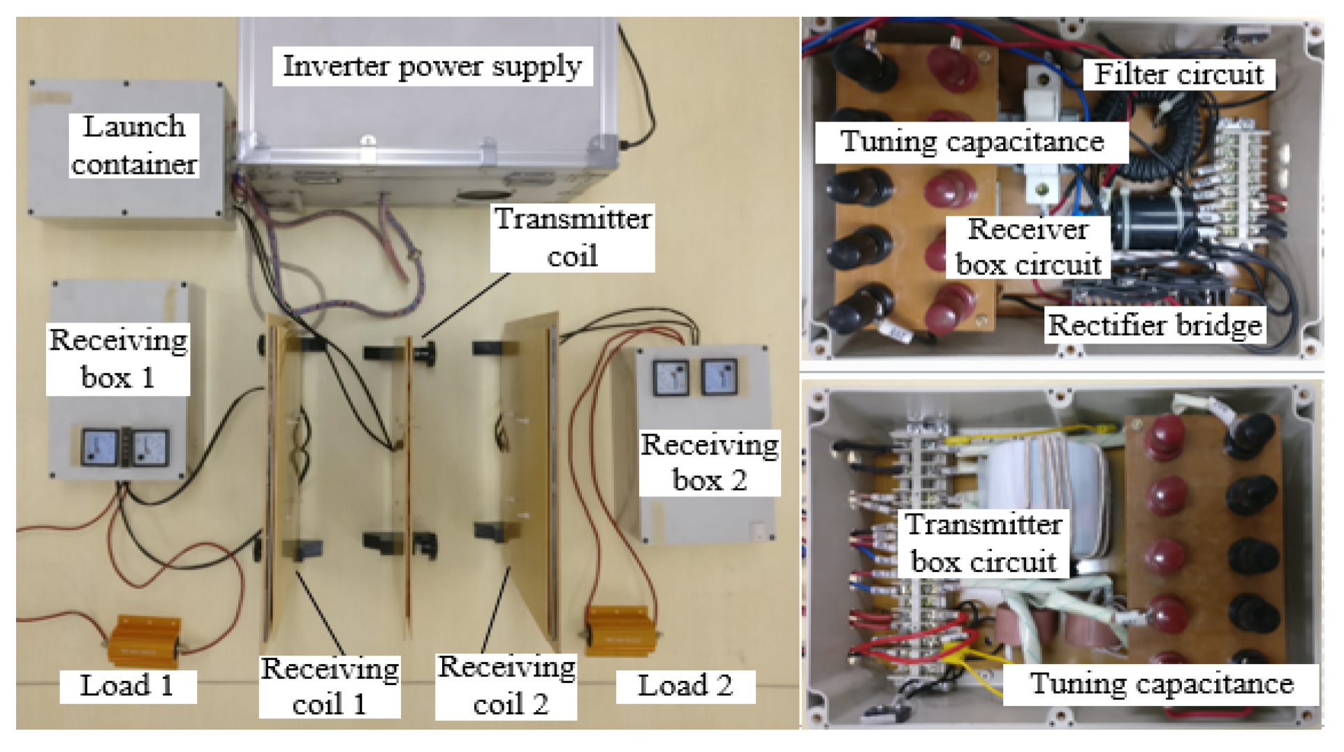
  • An experimental platform was built to verify the validity of the theory and simulation analysis.
The rest of the paper is organized as follows. The mathematical model of the dual-load electromagnetic coupling system is established through the circuit theory, and the energy efficiency expression of the system is deduced in section II. Combined with the mutual inductance expression between the coils, the effect of cross-coupling between the receiving coils on the efficiency of the system is analyzed in section III. With the help of electromagnetic field simulation software, the magnetic field distribution characteristics of the system and the transmission characteristics of the dual-load wireless power transmission system in the spatial scale of the four coupling coils and the change of load impedance are studied in section IV. The validity of the above analysis is verified by experimental analysis in section V. Section VI concludes the paper.

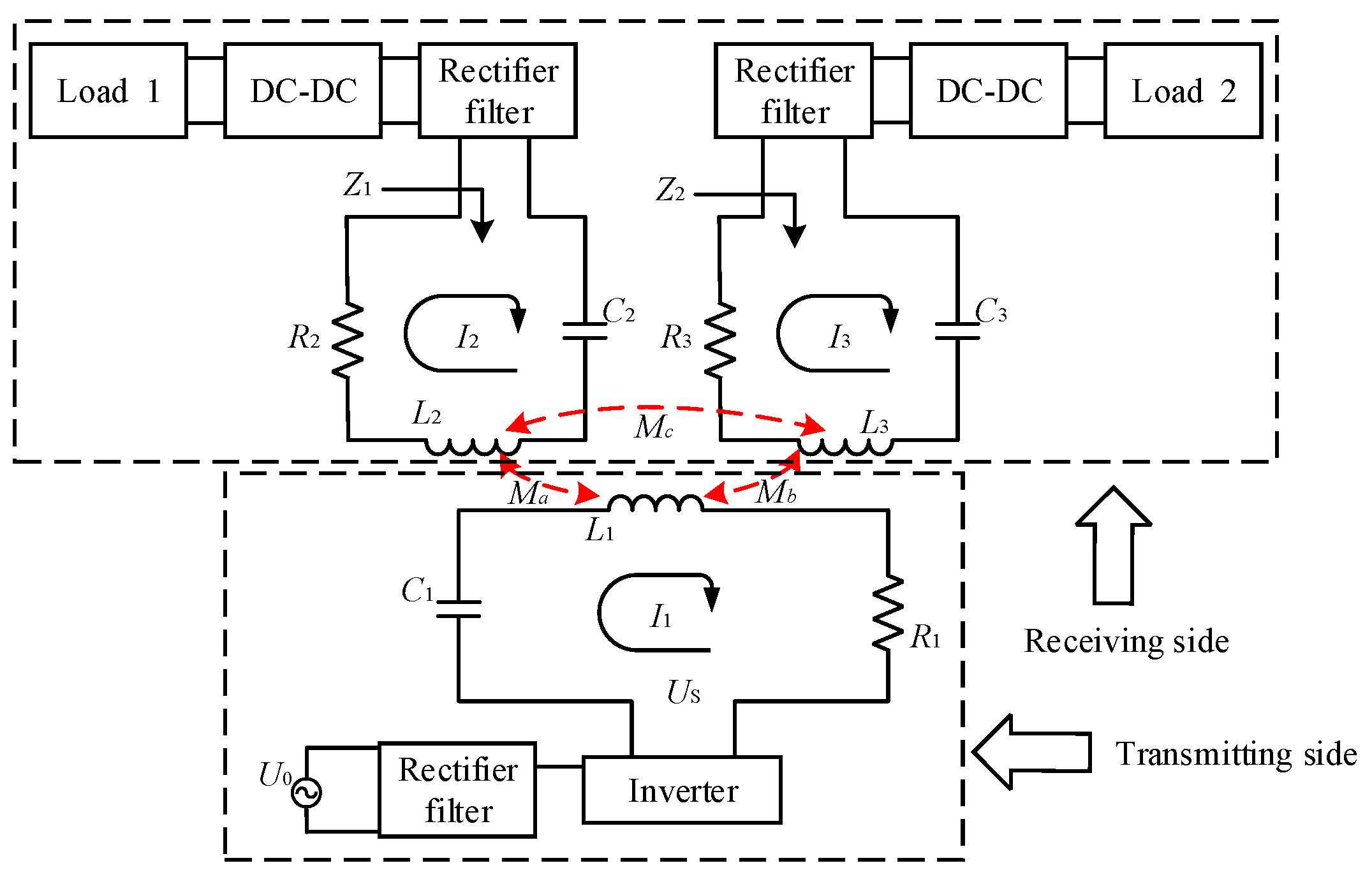
2. Modeling and Analysis of the Dual-Load Cooperative Coupling System

2.1. Equivalent Circuit Model

Figure 1 shows the equivalent circuit model of the dual-load cooperative coupling system where US is the high-frequency inverter output voltage of the system. I1, I2, and I3 are the current values of the transmitting coil, the receiving coil on the load 1 side and the receiving coil on the load 2 side, respectively. L1, L2, and L3, C1, C2, and C3, and R1, R2, and R3 are the inductance, capacitance, and equivalent internal resistance of the transmitting coil, the receiving coil on the load 1 side, and the receiving coil on the load 2 side, respectively. Z1 and Z2 are the equivalent load impedances of the receiving coils on the load 1 side and the load 2 side, respectively. Ma, Mb, and Mc are the mutual inductance between the transmitting coil and the two receiving coils and the mutual inductance between the two receiving coils, respectively.

2.2. Analysis of the Efficiency of the Coupled System

According to Ohm’s law and Kirchhoff’s law, the system state equation in Figure 1 can be expressed as:
[ U ˙ S 0 0 ] = [ Z P j ω M a j ω M b j ω M a Z S1 j ω M c j ω M b j ω M c Z S2 ] [ I ˙ 1 I ˙ 2 I ˙ 3 ]
When the system is in resonance and the load is purely resistive, the equivalent impedance of the transmitting loop is ZP = R1, the equivalent impedance of receiving loop 1 is ZS1 = Ra, and the equivalent impedance of receiving loop 2 is ZS2 = Rb. In addition, the coupling coefficient between the transmitting coil and the receiving coil on the load 1 side and the load 2 side is ka and kb. The coupling coefficient between the two receiving coils is kc. The quality factors of the system transmitting loop, load 1 receiving loop, and load 2 receiving loop are Q1, Q2, and Q3, and they can be expressed as:
{ k a = M a L 1 L 2 k b = M b L 1 L 3 k c = M c L 2 L 3 Q 1 = ω L 1 R 1 Q 2 = ω L 2 R a Q 3 = ω L 3 R b
By solving equation (1) and combining equation (2), the output power of side 1 and side 2 of the system load can be deduced as:
P 1 = | I 2 | 2 R a = U S 2 Q 1 Q 2 ( k a 2 + k b 2 k c 2 Q 3 2 ) / ( k a 4 Q 1 2 Q 2 2 +   ( 1 + k b 2 Q 1 Q 3 + k c 2 Q 2 Q 3 ) 2 + 2 k a 2 Q 1 Q 2 ( 1 + k b 2 Q 1 Q 3   + k c 2 Q 2 Q 3 + 2 k b 2 k c 2 Q 1 Q 2 Q 3 2 ) ) R 1
P 2 = | I 3 | 2 R b = U S 2 Q 1 Q 3 ( k b 2 + k a 2 k c 2 Q 2 2 ) / ( k a 4 Q 1 2 Q 2 2 +   ( 1 + k b 2 Q 1 Q 3 + k c 2 Q 2 Q 3 ) 2 + 2 k a 2 Q 1 Q 2 ( 1 + k b 2 Q 1 Q 3   + k c 2 Q 2 Q 3 + 2 k b 2 k c 2 Q 1 Q 2 Q 3 2 ) ) R 1
From Equations (3) and (4), the system transmission efficiency can be obtained as:
η = P 1 + P 2 P i n = ( k a 2 Q 1 Q 2 + k b 2 Q 1 Q 3 ) /   ( 4 k a 2 k b 2 k c 2 Q 1 2 Q 2 2 Q 3 2 + ( 1 + k a 2 Q 1 Q 2 + k b 2 Q 1 Q 3 + k c 2 Q 2 Q 3 ) 2 )
We can see from Equations (2)–(5) that the main parameters that affect system performance are the quality factor of the transmitting loop and the receiving loop and the coupling coefficient between them. When the system is determined and working at a fixed frequency, the quality factor is determined mainly by the load resistance, and the coupling coefficient is determined by the mutual inductance between the coils. The following will analyze the transmission characteristics of the dual-load wireless power transmission system for different resistive load charging and coupling coils distributed in four different positions of coaxial opposite sides, coaxial same side, different axis same side, and different axis coplanar.

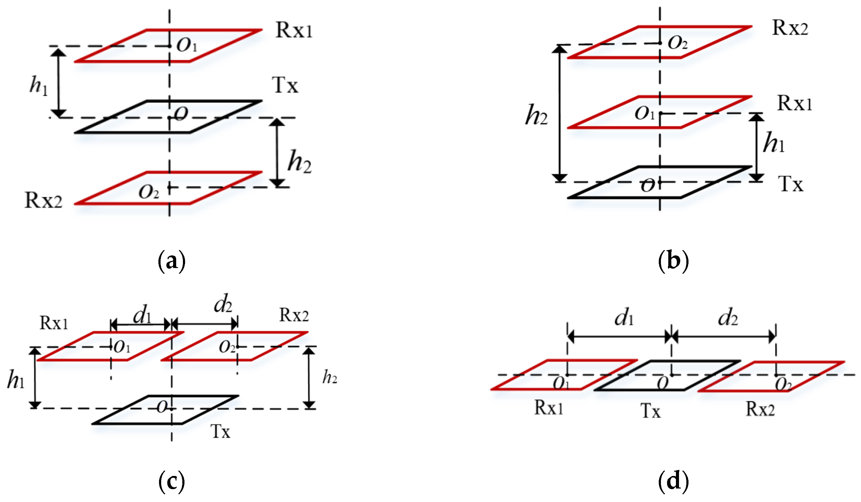
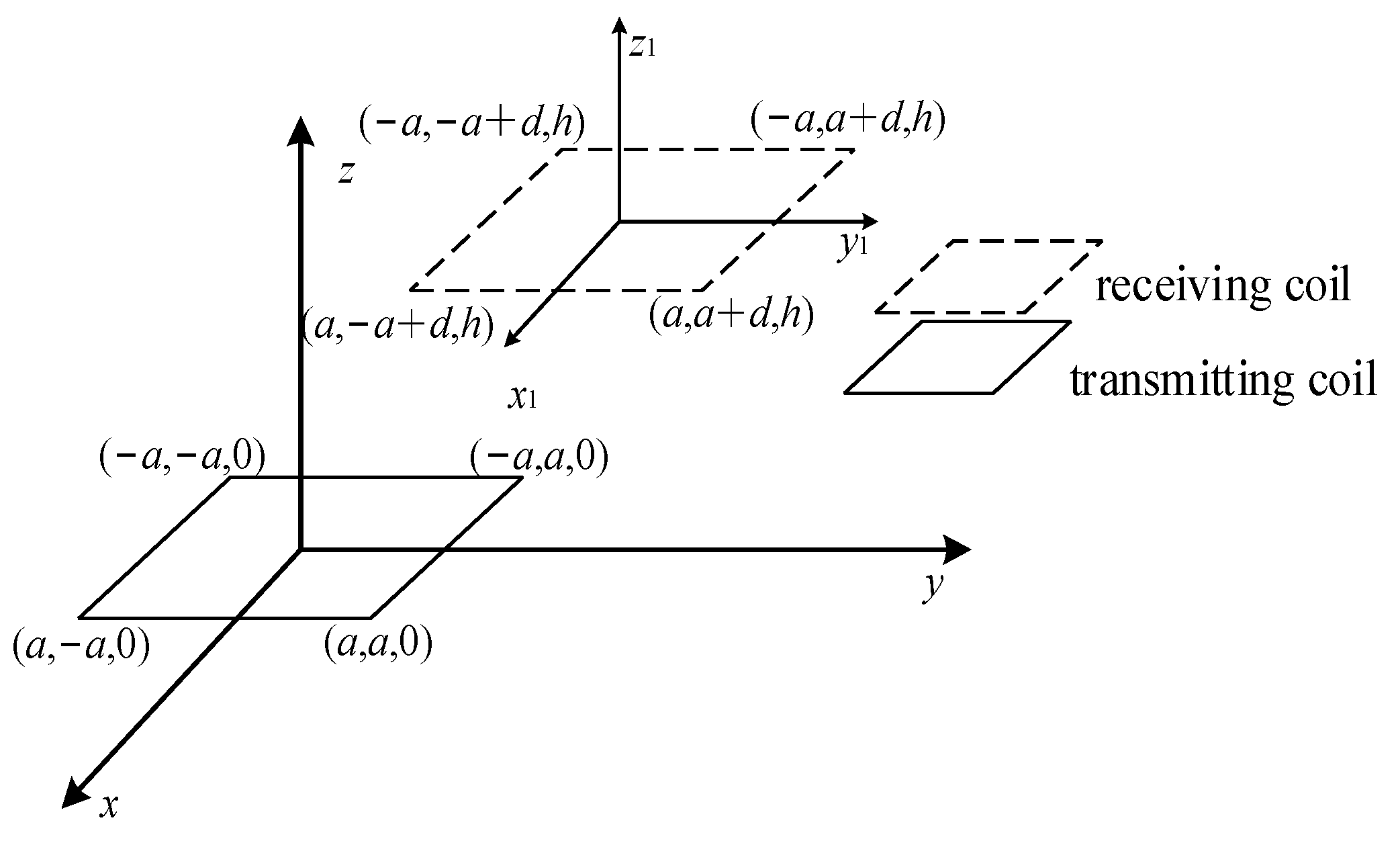
3. Analysis of Coil Cross-Coupling Coefficient

Excessive cross-coupling between the main channels of non-electromagnetic energy flow will interfere with the working state of the system, resulting in lower transmission efficiency. In a dual-load wireless power transmission system, the different positions of the receiving coils lead to different degrees of the influence of cross-coupling. Figure 2 shows the spatial position distribution of the coupling coil. According to the different spatial distribution of the double load, the parameter diagram of the relative position between any load coil and the transmitting coil can be drawn, as shown in Figure 3.
From the theoretical analysis, we know that the coupling effect between coils is determined by mutual inductance. According to Figure 3 and combined with electromagnetic field theory, the analytical formula of mutual inductance between coils at any position in space can be obtained:
M = μ 0 π ( ln 2 a + 4 a 2 + h 2 2 a + 4 a 2 + h 2 + a ln 2 a + 4 a 2 + d + h 2 2 a + 4 a 2 + d + h 2   a ln 2 a + 8 a 2 + h 2 2 a + 8 a 2 + h 2 + 2 4 a 2 + ( 2 a d ) 2 + h 2   2 a ln 2 a + 4 a 2 + ( 2 a d ) 2 + h 2 2 a + 4 a 2 + ( 2 a d ) 2 + h 2 4 a 2 + d + h 2   + 2 a ln 2 a + 4 a 2 + ( 2 a + d ) 2 + h 2 2 a + 4 a 2 + ( 2 a + d ) 2 + h 2 + 8 a 2 + h 2   + h + d + h 2 2 4 a 2 + h 2 2 ( 2 a + d ) 2 + h 2   2 ( 2 a d ) 2 + h 2 + 2 4 a 2 + ( 2 a + d ) 2 + h 2 )
In the above formula, 2a is the side length of the coil, h is the axial distance of the coil, and d is the radial distance of the coil. Combined with Equations (2) and (5), the relationship between the total efficiency η of the dual-load wireless power transmission system and the distribution of the coil space position can be obtained under the influence of cross-coupling factors, such as η = f(h1, h2, d1, d2).
By analyzing the expression, we know that the cross-coupling between the receiving coils is determined by the axial distances h1 and h2 between the receiving coil and the transmitting coil in the case of coaxial opposite-side coupling. The system efficiency shows a continuous decreasing trend when cross-coupling is ignored and shows a trend of first increasing and then decreasing when cross-coupling is considered. The result is shown in Figure 4a. When the axial distance between the receiving coils is short, the cross-coupling coefficient kc has a greater influence on the system efficiency than ka and kb. The weakening effect of the cross-coupling between the receiving coils makes the system at a lower power and efficiency level. When the coupling distance h1 and h2 increase at the same time, the coupling coefficient between the coils will decrease. However, because the distance between the two receiving coils is the sum of the coupling distance h1 and h2, the coupling coefficient kc will be greatly attenuated. Therefore, the transmission efficiency of the system will increase in a certain range when the coupling distance begins to increase. When the axial distance between the receiving coils reaches a certain level, the influence of ka and kb on the system efficiency is dominant, and the transmission efficiency decreases with the increase of the axial distance. In the case of coaxial same-side coupling, the cross-coupling between the receiving coils is determined by the axial distance h2h1 between receiving coil 2 and receiving coil 1. We make h1 constant. When we increase h2, the system efficiency presents two completely opposite trends in the initial stages of ignoring cross-coupling and considering cross-coupling, as shown in Figure 4b. Here, the cross-coupling coefficient kc decreases, and kc plays a major role, leading to an increase in system efficiency in the initial stage. In the case of coplanar coupling on the same side of the different axes, the coupling between the receiving coils depends on the radial distance between the two. During the synchronous increase in d1 and d2, the transmission efficiency of the two systems continues to decrease. However, the cross-coupling between the former receiving coils has a small effect on the efficiency, with a maximum difference of only 2%. The latter has no effect on the system efficiency. These situations are shown in Figure 4c,d.
In summary, when the distance between the receiving coils of the dual-load wireless power transmission system is relatively close in the case of coaxial opposite-side and coaxial same-side coupling, the cross-coupling will change the transmission efficiency trend of the system. However, the cross-coupling effect of the receiving coil is so small in the case of different axes same side that the cross-coupling effect of the receiving coil can be ignored.

4. Analysis of Transmission Parameters of Electromagnetic Coupling System

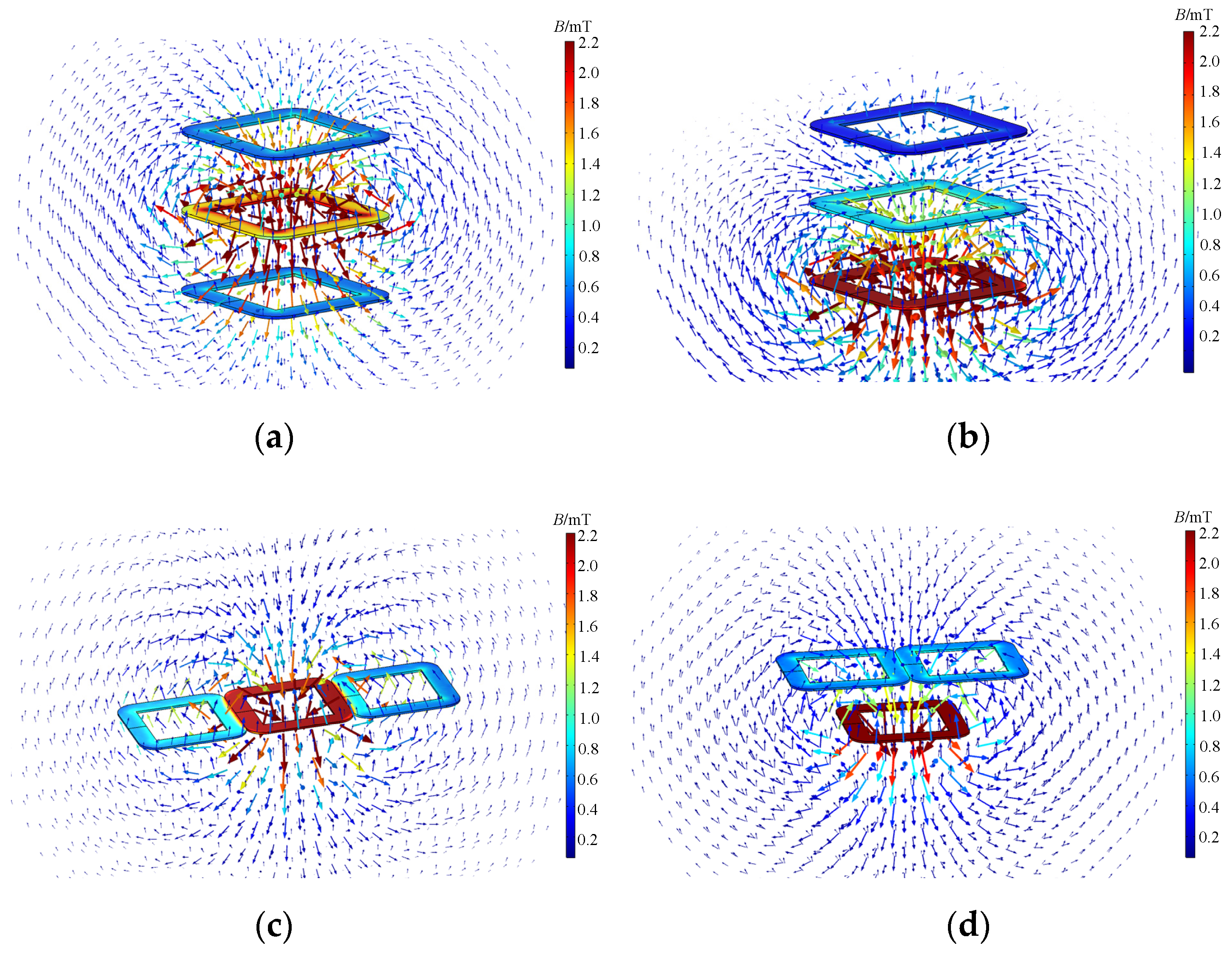
4.1. Finite Element Simulation Model

To perform intuitive and quantitative data analysis on the distance characteristics between the coupled coils and the load impedance in the dual-load wireless power transmission system, this paper uses multi-physics coupling analysis software to establish the electromagnetic simulation model of the system in the case of coaxial opposite side, coaxial same side, different axis same side, and different axis coplanar coupling (see Figure 5). In the model, the power excitation amplitude is 50 V, the working frequency is 110 kHz, the compensation topology type is SS, the outer diameter of the square coil is 30 cm, the inner diameter of the square coil is 25 cm, and the inductance of the coil is 109.86 µH.

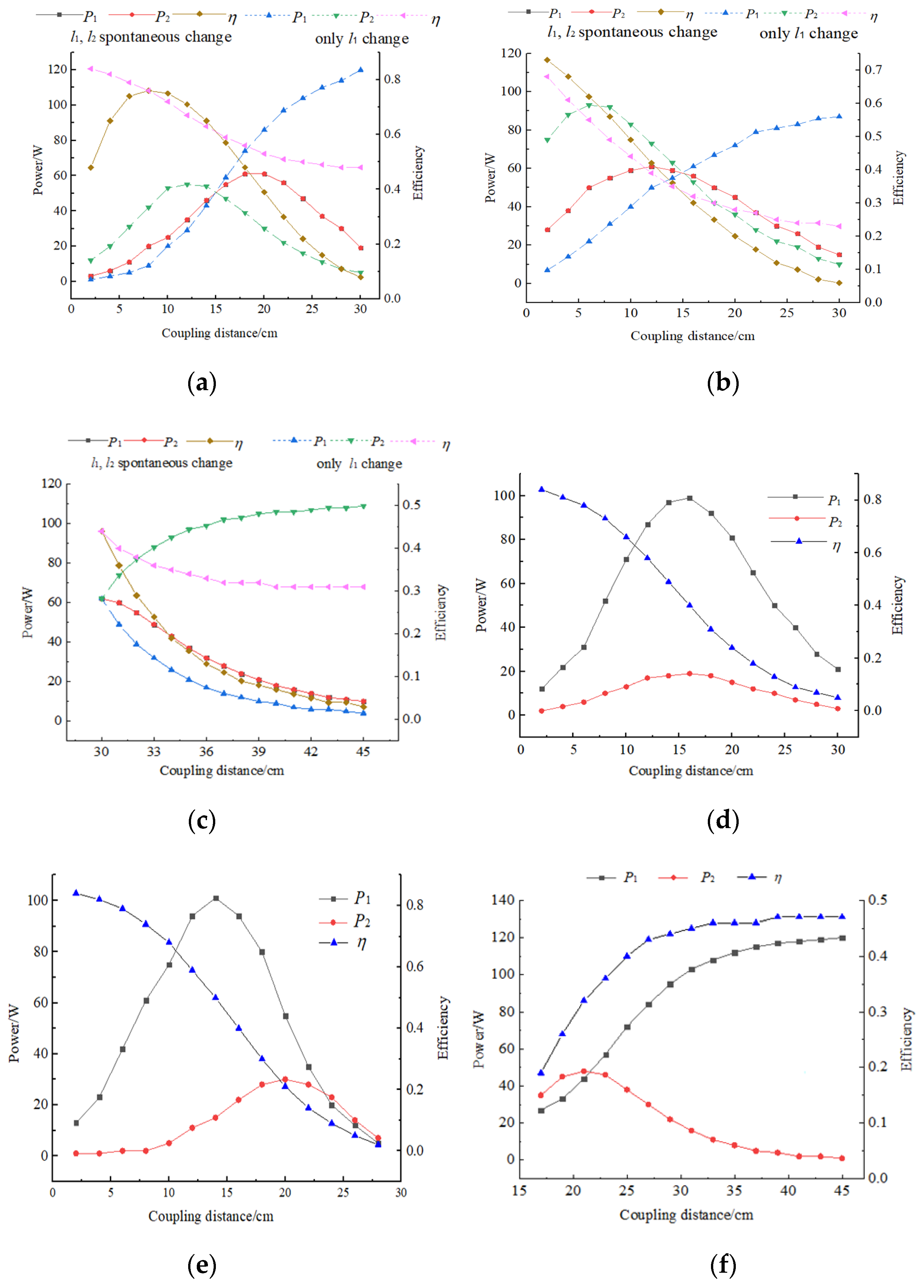
4.2. Analysis of Distance Characteristics

The coupling distance between the coils in the wireless power transmission system is one of the main factors affecting the transmission performance of the system. In the dual-load wireless power transmission magnetic coupling system, the coupling distance includes the coupling distance l1 and l2 between the receiving coil and the transmitting coil. Therefore, this paper mainly analyzes the system characteristics when the coupling distances l1 and l2 change synchronously and when a single coupling distance l1 or l2 changes.
Figure 6 is the curve of the coupling distance of the transceiver coil and the system parameters when the system is connected to the coaxial opposite side. It can be seen from the figure that as the coupling distance l1 and l2 increase at the same time, and the receiving power of load 1 and load 2 has the same trend of increasing first and then decreasing. When the coupling distance is 20 cm, both of them reach the maximum value of 78.14 W. The system transmission efficiency also changes in the same way, reaching a maximum of 0.86 when the coupling distance is 8 cm. In the process of increasing the coupling distance l1, when the coupling distance is 12 cm, the power of load 1 reaches a maximum of 71.26 W, the power of load 2 continues to increase, and the system transmission efficiency continues to decrease. It can be seen from the above curves that when the coupling distances l1 and l2 change at the same time, the variation trend of the system transmission efficiency is consistent with the results of the cross-coupling analysis in Figure 4a, which indicates that the cross-coupling effect between the receiving coils reduces the transmission efficiency of the system when the distance between the double loads is close in the case of coaxial opposite side. When only the coupling distance l1 changes, the change trend of load 1 is the same as that of single transmitting and single receiving systems. The receiving power of load 2 continues to increase. Because only l1 changes at this time, it will not cause a significant decrease in cross coupling, so the overall transmission efficiency is gradually decreasing. In summary, in the case of coaxial hetero-lateral coupling, when the coupling distance l1 and l2 change synchronously, and only l1 or l2 change, the load power of the coupling distance change has the same change rule as that of the single-transmitting and single-receiving load, but the power extreme points in the two cases are different. When the coupling distance of a single load changes, the received power of the load with constant coupling distance increases monotonically.
As shown in Figure 7, in the case of coaxial coupling on the same side, when the coupling distance l1 and l2 increase at the same time, the power of load 1 and 2 rises first and then drops, but the numerical difference is obvious, and the maximum difference is 102.93 W. Because the relative position of the two receiving coils is unchanged during the whole process, the same change trend is presented. When only l1 is increased, the power of load 1 and load 2 first rises and drops. When l1 is 23 cm, the power of both is 35.93 W, but the efficiency is only 0.21. When only l2 increases, the power of load 2 rises first and then drops, the output power of load 1 continues to increase, and the system transmission efficiency continues to increase. When l2 is 21 cm, the power of both is 57.61 W, but the efficiency is only 0.29. The analysis shows that the change trend of the system transmission efficiency is opposite in the above two cases. This is mainly because when l1 increases, the distance between the two receiving coils droups first and then rises, and when l2 changes, the distance between the two receiving coils continues to decrease. Combined with the analysis of the system transmission efficiency in Figure 4b, it is shown that in the double-load radio transmission system with coaxial coupling on the same side, when the distance between the receiving coils is small, the overall transmission efficiency of the system will be low due to the influence of cross coupling.
Figure 8a is a curve of the coupling distance between the transmitting and receiving coils and the system parameters when the system is coupled on the same side of the different axes. We can see from the figure that when the coupling distances l1 and l2 increase simultaneously, the power of load 1 and load 2 both first increase and then decrease. When l1 and l2 are 12 cm, the power of both reaches the maximum value of 80.76 W, and the efficiency continues to decline. When only the coupling distance l1 increases, the power of load 1 first increases and then decreases. When l1 is 6 cm, the power reaches the maximum value of 119.30 W, and the power of load 2 continues to increase. From the above analysis, we can see that the dual-load wireless power transmission system has the same power change rule in the case of the coupling between the same side of the different axis and the opposite side of the coaxial, but the law of the efficiency change is different. When l1 and l2 increase simultaneously, the efficiency of the former continues to decrease, while the efficiency of the latter first increases and then decreases, and the maximum value is 0.85. As shown in Figure 8b, when the system is in a coplanar situation with different axes, when the coupling distances l1 and l2 increase simultaneously, the power and efficiency of the system continue to decrease from 79.49 W and 0.5. When only the coupling distance l1 increases, the power of load 1 decreases, the power of load 2 increases, and the system efficiency continues to decrease.
These results show that in the dual-load wireless power transmission system, both the function of the load receiving power and the coupling distance of the transmitting and receiving coils and the function relationship between the system efficiency and the coupling distance of the transmitting and receiving coils are monotonic in the case of different axes and coplanarities, and the maximum efficiency of the system is only 0.5.

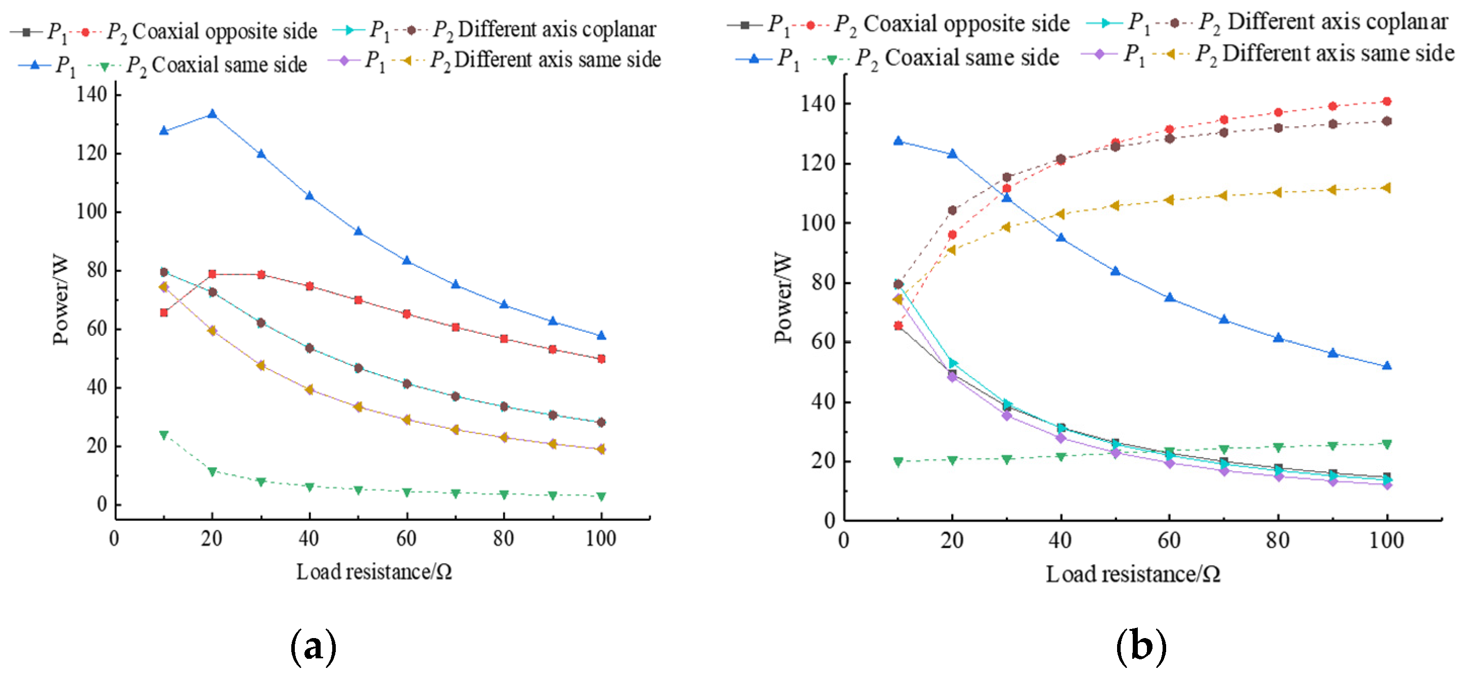
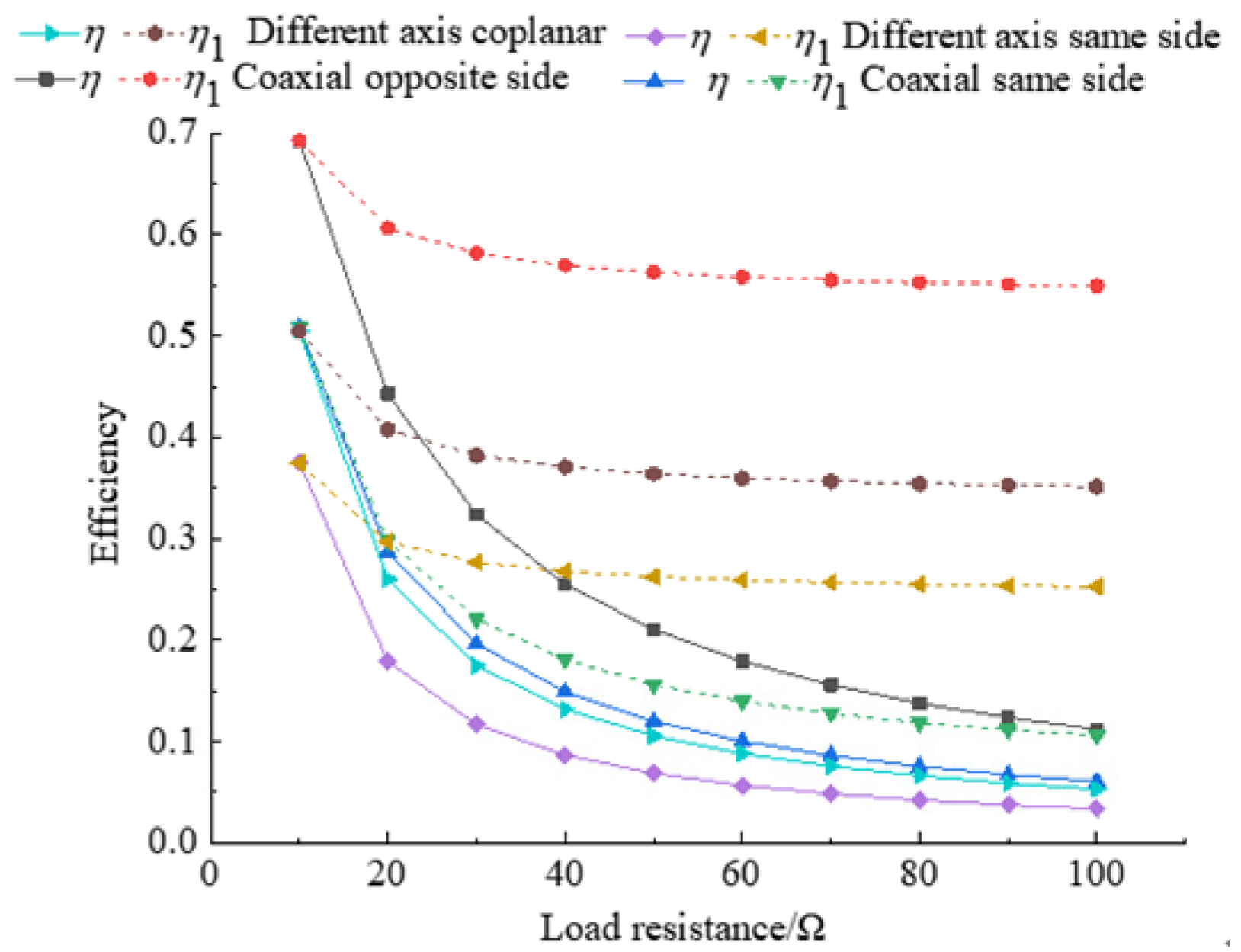
4.3. Analysis of Impedance Characteristics

When analyzing the impedance characteristics of the dual-load wireless power transmission system, we analyzed the two situations of the simultaneous change in the dual-load impedance and the change in the single-load impedance.
Figure 9 shows the received power curve of the system under four coupling situations when the load impedance changes. Figure 9a shows that when the load resistance changes synchronously, the received power of the load under the condition of the same side of the different axes and the coplanar coupling of the different axes continues to decrease. When the coupling coil is on the other side of the coaxial cable and the same side of the coaxial cable, the power of load 1 and the power of load 2 in the former reach the maximum value of 78.76 W when the load impedance is 20 Ω, and the power of load 1 in the latter reaches the maximum value of 133.42 W when the load impedance is 20 Ω. Figure 9b shows that in the process of increasing the resistance of load 1, the received power of load 1 and the received power of load 2 in the four systems both decrease. These results indicate that when the resistance of the dual-load changes synchronously, the system has an optimal load that maximizes the power of the dual-load in the case of coaxial opposite-side coupling. In the case of coaxial same-side coupling, there is an optimal load for the load power close to the transmitting coil. When the resistance of a single load changes, in the four coupling cases, the changed resistance is always negatively correlated with the received power of its own load and positively correlated with the received power of the other load.
Figure 10 shows the efficiency curve when the load resistance changes under four coupling conditions, in which ƞ is the efficiency when both loads change simultaneously, and ƞ1 is the efficiency when load 1 changes. The figure shows that when the load increases, the efficiency of the system decreases, and only when load 1 increases does the system efficiency decrease less than when loads 1 and 2 increase simultaneously. Due to the asymmetrical distribution of the receiving coils of the system in the case of coaxial coupling on the same side, it is necessary to analyze the transmission characteristics of the system when its load 2 resistance changes.
As shown in Figure 11, when the resistance of load 2 increases, the received power of load 1 increases, the received power of load 2 decreases, and the system transmission efficiency increases. When the coil 1 has greater influence on the system than receiving coil 2. The increase in the resistance of load 2 will cause the transmission efficiency of receiving coil 1 to increase, thereby increasing the overall efficiency of the system. These results show that the load resistance of the system is negatively related to the system efficiency and is related to the number of load changes in the case of coaxial opposite sides, different axes on the same side, and different axis coplanar couplings. In the case of coaxial coupled on the same side, the increase in load 1 reduces the system efficiency, and the increase in load 2 increases the system efficiency.

5. Experiment and Analysis

To verify the validity of the theory and simulation analysis, we built an experimental platform for the dual-load wireless power transmission system, which is shown in Figure 12. The output amplitude of the high-frequency power supply in the experimental platform is 50 V, the transmitting and receiving coils are all square coils with a side length of 30 cm, and the working frequency is 110 kHz. Before the experiment, we measured the inductance of the coil with an impedance analyzer and matched the capacitance tuning according to the inductance. The specific parameters of the system are shown in Table 1.
When we change the transmission distance, the power and efficiency of the system in the four coupling situations are shown in Figure 13. The figure shows that the experimental results are in good agreement with the simulation analysis. In addition, due to the difference between the hand-wound coil used in the experiment and the ideal coil model in the simulation, the experimental data are slightly smaller in value than the simulation data. When the dual-load wireless power transmission system is coplanar on different axes, both the functional relationship between the coupling distance of the transceiver coil and the received power of the load and the functional relationship between the transceiver coil and the system efficiency are monotonic. The maximum efficiency is only 0.43, showing that this situation is not suitable for power transmission. In the case of coaxial coupling on the same side, when the coupling distances l1 and l2 are 16 cm and 31 cm, the power of loads 1 and 2 reach extreme values of 99.40 W and 19.73 W, respectively. The power of dual loads has a large difference and is suitable for charging electrical equipment with different power requirements. In the case of coaxial opposite side and different axis same side coupling, when the coupling distances l1 and l2 change synchronously, the power of both loads can reach the extreme point. The former achieves an extreme value of 61.39 W when the coupling distances are 19 cm, and the latter achieves an extreme value of 61.42 W when the coupling distances are 12 cm. However, only the system efficiency of the former reaches the maximum value of 0.78 when the coupling distance is 8 cm. When only l1 or l2 changes, the load power where the coupling distance changes can reach the extreme point. The former obtains an extreme value of 55.35 W when l1 or l2 is 12 cm, and the latter obtains an extreme value of 93.55 W when l1 or l2 is 6 cm.
When the load resistance changes, the power and efficiency of the system under four coupling conditions are shown in Figure 14. It can be seen from the diagram that when the resistance of the two loads increases at the same time, the double load power increases first and then decreases in the case of coaxial opposite side coupling, and the load power decreases monotonously in the other three cases. When only any resistance value of the double load is increased, the change of the load power is the same under the four coupling conditions, that is, the load power with increased resistance value is monotonously small, and the load power with resistance value increases is monotonously. When the load 2 far away from the transmitting coil is increased in the case of coaxial coupling, the transmission efficiency of the system increases monotonously, and the transmission efficiency of the system decreases monotonously with the increase of the load resistance in the other three cases.

6. Conclusions

This paper analyzes and verifies the coupling characteristics of the dual-load wireless power transmission system in the four cases of coaxial different sides, coaxial same side, different axis same side, and different axis coplanar coil positions in space. The specific conclusions are as follows.
When the distance between the receiving coils of the dual-load radio transmission system is close, the cross coupling between the receiving coils will reduce the transmission efficiency of the system when the coupling is on the opposite side of the coaxial line and on the same side of the coaxial line. At this time, the influence of cross coupling can be weakened by increasing the coupling distance of the double load and the coupling distance of the far side load, respectively. In the case of different axis on the same side and different axis coplanar coupling, the influence of cross coupling is very small, and the cross coupling between receiving coils can be ignored.
When the dual-load wireless power supply system works on the opposite side of the coaxial and the same side of different axes, in the process of increasing the coupling distance l1 and l2, the load power of the coupling distance change side increases first and then decreases, and the load power of the coupling distance constant side continues to increase. The system transmission efficiency only has a maximum point when the coupling distance l1 and l2 increase at the same time in the case of the coaxial opposite side, and in the other cases, it decreases monotonously with the increase of the coupling distance. In the case of coaxial ipsilateral coupling, when the coupling distance l1 and l2 increase at the same time and only increase l1, the power of the two loads increases first and then decreases, and the transmission efficiency of the system decreases monotonously. When the coupling distance l2 increases, the power of load 2 increases first and then decreases, and the power of load 1 and the transmission efficiency of the system increase monotonously. During the whole change process, the received power of the two loads is quite different, which is suitable for electrical equipment with different power requirements. In the case of non-coplanar coupling, the maximum transmission efficiency of the system is only 0.43, not suitable for power transmission.
When the dual-load wireless power transmission system is coupled with different sides of the coaxial, same side of different axes, and coplanar coupling of different axes, the load resistance is negatively related to the system efficiency. The greater the number of load changes, the greater the correlation coefficient. When the resistance of load 2 increases in a system on the same side of the coaxial cable, the system efficiency increases. When the two load resistance values change synchronously, only the power of loads 1 and 2 in the coaxial opposite side system has a maximum value. When a single load changes, its resistance is negatively correlated with the received power and positively correlated with the received power of a constant load.
The above analysis of the system characteristics in the four possible coupling situations in the dual-load wireless power transmission system has laid a certain theoretical foundation for the practical application of this technology in multiload cooperative wireless charging.

Author Contributions

Writing—original draft preparation M.X. and H.H.; writing—review and editing, L.L. and J.G.; data curation, P.Z. and G.Z. All authors have read and agreed to the published version of the manuscript.

Funding

This research was funded by the National Natural Science Foundation of China and Tianjin Natural Science Foundation, grant number 52077153 and 20JCYBJC00190.

Conflicts of Interest

The authors declare no conflict of interest.

References

  1. Zhang, Z.; Pang, H.; Georgiadis, A. Wireless Power Transfer—An Overview. IEEE Trans. Ind. Electron. 2019, 66, 1044–1058. [Google Scholar] [CrossRef]
  2. Famili, A.; Stavrou, A. Eternal Flying: Optimal Placement of Wireless Chargers for Nonstop Drone Flights. In Proceedings of the 2022 International Conference on Electrical, Computer and Energy Technologies (ICECET), Prague, Czech Republic, 20–22 July 2022; pp. 1–6. [Google Scholar] [CrossRef]
  3. Yang, L.; Feng, B.; Zhang, Y.; Li, X.; Zhang, L.; Chen, X.; Nie, J.; Wen, H.; Tian, J.; Jian, J.; et al. Single Wire Capacitive Wireless Power Transfer System for Wearable Biomedical Sensors based on Flexible Graphene Film Material. IEEE Trans. Biomed. Circuits Syst. 2022. [Google Scholar] [CrossRef] [PubMed]
  4. Zhan, B.; Liu, S. Efficiency analysis of 13.56 MHz flexible wearable electronic Magnetically coupled resonance wireless energy transfer. In Proceedings of the 2022 23rd International Conference on Electronic Packaging Technology (ICEPT), Dalian, China, 10–13 August 2022; pp. 1–4. [Google Scholar] [CrossRef]
  5. Chen, K.W.K.; Cheng, K.W.E. Review of magnetic resonance technology, recent research trends and issues in EV wireless charging. In Proceedings of the 11th IET International Conference on Advances in Power System Control, Operation and Management (APSCOM 2018), Hong Kong, China, 11–15 November 2018; pp. 1–7. [Google Scholar] [CrossRef]
  6. Singh, A.; Singh, M. Design and Implementation of Wireless Power Transfer Using Class-E Resonant Inverter and Magnetic Resonance Coupling. In Proceedings of the 2022 IEEE IAS Global Conference on Emerging Technologies (GlobConET), Arad, Romania, 20–22 May 2022; pp. 987–992. [Google Scholar] [CrossRef]
  7. Baikova, E.N.; Baikov, A.V.; Romba, L. Resonance Tuning in Wireless Energy Transfer System. In Proceedings of the 2022 4th Global Power, Energy and Communication Conference (GPECOM), Nevsehir, Turkey, 14–17 June 2022; pp. 156–161. [Google Scholar] [CrossRef]
  8. Chung, Y.D.; Lee, C.Y. Effect and Influence of Double Resonance Couplings with Dual Resonance Frequencies for Wireless Power Multi-Charging Module in Superconducting MAGLEV Train. IEEE Trans. Appl. Supercond. 2022, 32, 3602806. [Google Scholar] [CrossRef]
  9. Demarchou, E.; Psomas, C.; Krikidis, I. On the Design of Magnetic Resonant Coupling for Wireless Power Transfer in Multicoil Networks. IEEE Wirel. Commun. Lett. 2022, 11, 406–410. [Google Scholar] [CrossRef]
  10. Rong, C.; He, X.; Wu, Y.; Qi, Y.; Wang, R.; Sun, Y.; Liu, M. Optimization Design of Resonance Coils with High Misalignment Tolerance for Drone Wireless Charging Based on Genetic Algorithm. IEEE Trans. Ind. Appl. 2022, 58, 1242–1253. [Google Scholar] [CrossRef]
  11. Zhang, Y.; Zhao, Z.; Chen, K. Frequency splitting analysis of magnetically-coupled resonant wireless power transfer. In Proceedings of the 2013 IEEE Energy Conversion Congress and Exposition, Denver, CO, USA, 15–19 September 2013; pp. 2227–2232. [Google Scholar] [CrossRef]
  12. Li, H.; Wang, K.; Huang, L.; Li, J.; Yang, X. Coil structure optimization method for improving coupling coefficient of wireless power transfer. In Proceedings of the 2015 IEEE Applied Power Electronics Conference and Exposition (APEC), Charlotte, NC, USA, 15–19 March 2015; pp. 2518–2521. [Google Scholar] [CrossRef]
  13. Mohammad, M.; Pries, J.L.; Onar, O.C.; Galigekere, V.P.; Su, G.-J.; Wilkins, J. Comparison of Magnetic Field Emission from Unipolar and Bipolar Coil-Based Wireless Charging Systems. In Proceedings of the 2020 IEEE Transportation Electrification Conference & Expo (ITEC), Chicago, IL, USA, 23–26 June 2020; pp. 1201–1207. [Google Scholar] [CrossRef]
  14. Hou, R.; Wang, X.; Wu, J.; Song, H.; Qu, Y. Research and Application of Dual-Load wireless power Transmission System. In Proceedings of the 2019 22nd International Conference on Electrical Machines and Systems (ICEMS), Harbin, China, 11–14 August 2019; pp. 1–5. [Google Scholar] [CrossRef]
  15. Cheng, C.; Zhou, Z.; Li, W.; Zhu, C.; Deng, Z.; Mi, C.C. A Multi-Load Wireless Power Transfer System with Series-Parallel-Series Compensation. IEEE Trans. Power Electron. 2019, 34, 7126–7130. [Google Scholar] [CrossRef]
  16. Zhou, Z.; Shi, Q.; Cheng, C.; Li, W.; Deng, Z.; Li, F.; Mi, C. A Multi-load Wireless Power Transfer System with Constant Voltage Outputs Using S-LCC Compensation. In Proceedings of the 2019 22nd International Conference on Electrical Machines and Systems (ICEMS), Harbin, China, 11–14 August 2019; pp. 1–6. [Google Scholar] [CrossRef]
  17. Cannon, B.L.; Hoburg, J.F.; Stancil, D.D.; Goldstein, S.C. Magnetic Resonant Coupling As a Potential Means for Wireless Power Transfer to Multiple Small Receivers. IEEE Trans. Power Electron. 2009, 24, 1819–1825. [Google Scholar] [CrossRef]
  18. Fu, M.; Zhang, T.; Zhu, X.; Luk, P.C.-K.; Ma, C. Compensation of Cross Coupling in Multiple-Receiver Wireless Power Transfer Systems. IEEE Trans. Ind. Inform. 2016, 12, 474–482. [Google Scholar] [CrossRef]
  19. Lee, K.; Cho, D. Analysis of wireless power transfer for adjustable power distribution among multiple receivers. IEEE Antennas Wirel. Propag. Lett. 2019, 14, 950–953. [Google Scholar] [CrossRef]
  20. Luo, C.; Qiu, D.; Gu, W.; Zhang, B.; Chen, Y.; Xiao, W. Multiload Wireless Power Transfer System with Constant Output Power and Efficiency. IEEE Trans. Ind. Appl. 2022, 58, 1101–1114. [Google Scholar] [CrossRef]
Figure 1. Equivalent circuit model of a dual-load cooperative coupling system.
Processes 10 01931 g001
Figure 2. Spatial distribution of coupling coils. (a) Coaxial opposite side. (b) Coaxial same side. (c) Different axis same side. (d) Different axis coplanar.
Processes 10 01931 g002
Figure 3. Relative Position Diagram of Transceiver Coil.
Processes 10 01931 g003
Figure 4. Cross-coupling analysis in four coupling cases. (a) Coaxial opposite side. (b) Coaxial same side. (c) Different axes same side. (d) Different axis coplanar.
Processes 10 01931 g004
Figure 5. Four simulation models of wireless energy transmission. (a) Coaxial opposite side. (b) Coaxial same side. (c) Different axis same side. (d) Different axis coplanar.
Processes 10 01931 g005
Figure 6. The relationship between the coupling distance on the different sides of the coaxial and the system parameters.
Processes 10 01931 g006
Figure 7. The relationship between the coupling distance on the different sides of the coaxial and the system parameters. (a) l1, l2 change synchronously. (b) Only l1 changes. (c) Only l2 changes.
Processes 10 01931 g007
Figure 8. The relationship between the system parameters and the coupling distance of the same side and the same axis. (a) Different axis the same side. (b) Different axis coplanar.
Processes 10 01931 g008
Figure 9. System power curve as load resistance changes. (a) Double load. (b) Only load 1 changes synchronously.
Processes 10 01931 g009
Figure 10. Efficiency curve for load resistance changes.
Processes 10 01931 g010
Figure 11. System parameter curve when load 2 changes in coaxial same-side coupling.
Processes 10 01931 g011
Figure 12. The experiment platform.
Processes 10 01931 g012
Figure 13. Curve of coupling distance and system parameters. (a) Coaxial opposite side. (b) Different axis same side. (c) Different axis coplanar. (d) Synchronous changes in l1 and l2 on the same coaxial side. (e) Synchronous changes in l1 and l2 on the same coaxial side. (f) Only l1 changes on the same side of the coaxial.
Processes 10 01931 g013
Figure 14. Load resistance and system parameter curves. (a) Double load synchronous change. (b) Only load 1 changes. (c) Only load 2 changes on the same side of the coaxial. (d) Efficiency curve.
Processes 10 01931 g014
Table 1. Parameters of the transmitting and receiving coil.
SymbolTransmiting CoilReceiving Coil 1Receiving Coil 2
Inductance, L/µH107.82107.83107.82
Capacitance, C/nF19.7119.7019.71
Coil turns, N101010
Resistance, R0.110.090.12
Publisher’s Note: MDPI stays neutral with regard to jurisdictional claims in published maps and institutional affiliations.

