Article

Preparation and Optimization of Modified Asphalt by Profile Control Parameters at Lamadian Oilfield

1
Development Department of Daqing Oilfield Co., Ltd., Daqing 163000, China
2
Quality, Safety and Environmental Protection Supervision and Evaluation Center of Daqing Oilfield Co., Ltd., Daqing 163000, China
3
Exploration and Development Research Institute, Daqing Oilfield Co., Ltd., Daqing 163000, China
4
Key Laboratory of Enhanced Oil & Gas Recovery of Ministry of Education, Northeast Petroleum University, Daqing 163318, China
*
Author to whom correspondence should be addressed.
Processes 2022, 10(10), 1917; https://doi.org/10.3390/pr10101917
Submission received: 2 September 2022 / Revised: 16 September 2022 / Accepted: 19 September 2022 / Published: 22 September 2022
(This article belongs to the Topic Enhanced Oil Recovery Technologies, 2nd Volume)

Abstract

:
The Lamadian oilfield has entered the stage of strong water cut after natural energy development and conventional water flooding development. The use of asphalt binder for profile control can not only adjust the contradiction between layers, expand the swept volume, but also improve the oil displacement efficiency. The field test has achieved certain results. The main oil layer in the Lamadian oilfield has a strong oil layer thickness and serious vertical and plane heterogeneity. After years of water injection development and polymer injection development, most oilfields have entered a period of strong water cut. In the test, it is found that the effect of different well layers is very different, the effect is unstable, and the reason is unclear. Therefore, it is necessary to carry out research on the adaptability and parameter optimization of profile control of asphalt binder through laboratory experiments. In this paper, the asphalt binder provided on site are modified and the dispersion effect of modified asphalt binder is studied, and the concentration of suspending agent is optimized. The artificial cemented core structure and injection method are improved to solve the problem of aggregated asphalt binder on the end face during injection. The displacement profile control experiment was carried out with artificial cores, and the matching relationship between the injected particle size of the asphalt binder and the permeability was determined, and the optimal injection amount was optimized for cores with different permeabilities. The research results show that adding a KCl (potassium chloride solution) solution with a concentration of 2% as a dispersant can exert a better dispersing effect on the asphalt binder. Through the plugging rate experiments of three types of asphalt binder, the profile control effect is determined as the best when the particle size of the asphalt binder is 0.06–0.1 mm. According to the experimental results, the experimental research on the injection concentration and profile control radius of the profile control agent system was carried out. Finally, it was determined that the injection concentration of 3500 mg/L and the profile control radius of 1/3–1/2 of the well spacing were the optimal injection parameters. The field application of a profile control agent provides experimental basis.

1. Introduction

After years of water flooding, most of China’s oilfields have entered their middle and late stages of production. High-permeability strips and large pores are formed in the oil layer where the injection fluid flows, resulting in poor water flooding effect and low efficiency between injection and production wells. Regarding the water cycle, the economic benefits of extraction become worse, and there is still a large amount oil remaining in the reservoir [1]. In order to ensure the production of oilfields, all oilfields are actively researching profile control technology. Profile control has a blocking effect on high-permeability layers or large pore channels, thereby improving the water absorption profile, and at the same time increasing the start-up pressure of water injection in high-permeability layers, changing the flow direction of water, expanding the swept area, improving the recovery efficiency of water flooding, and prolonging the stable production time of the oil field [2]. P block is the main oil layer in the Lamadian oilfield. The oil layer is thick and has serious vertical and horizontal heterogeneity. After years of water injection development and polymer injection development, most oilfields have entered a period of high water cut. To fully tap the production potential of the oil layer, for the wells with seriously unbalanced injection profiles, various profile control methods have been tried successively, and certain effects have been seen. The swept volume of shallow profile control expansion is limited, and conventional chemical deep-profile control has problems such as large dose, high cost, and influence on injection [3]. According to the characteristics of the reservoir and the technical effect of profile control in the Lamadian oilfield, oilfield workers have studied the low-cost asphalt particle online injection profile control technology [4]. Asphalt particle profile control has the advantages of low cost and large profile control radius, but there are problems, such as serious adhesion and poor migration ability of asphalt binder during the injection process. On-site construction still relies on experience, and there is a certain blindness. In order to give full play to the role of asphalt binder in profile control, it is necessary to carry out laboratory core experiments to determine the matching relationship between the injected particle size and permeability of asphalt binder, and to optimize the parameters of asphalt binder for profile control.
From the 1950s to the 1970s in China: the plugging agent materials were mainly cement, resin, activated heavy oil, water glass, or calcium chloride [5]. From the 1970s to the 1980s: polymers and their cross-linked gels appeared, mainly with strong gel plugging agents, for the purpose of adjusting the water absorption profile and liquid production profile of the formation near the wellbore [6]. After the 1990s: the oil field entered a period of high water cut, and the pre-crosslinked binder, delayed crosslinked deep profile control agents, and related technologies were rapidly developed [7]. Zhang et al. [8] developed a profile control agent for deep formations with high permeability and large pore channels. Ren et al. [9] developed a precipitation-adjusting agent suitable for micro-fractured reservoirs and sandstone matrix reservoirs. It has the characteristics of low surface viscosity, is not affected by pH and temperature, and its permeability can be reduced by more than 90%. Li et al. [10] studied the profile control mechanism of asphalt binder. The Daqing oilfield used sand-filled pipes to conduct experiments to determine the particle size of asphalt binder for profile control. A piston-type asphalt pump is used to solve the sticking phenomenon of asphalt binder, and the technology is applied to the field, which proves that the asphalt binder can achieve a better profile control effect. Liu et al. [11] developed a polymer jelly plugging agent suitable for sandstone, limestone, dolomite, and other formations. The plugging agent uses amphoteric polymers to react with crosslinking agents to form jelly. Amphoteric polymers are selected. The natural water plugging technology has seen obvious results in oilfields such as Texas. In order to study the plugging performance, erosion resistance performance, and selective plugging rate performance of modified asphalt binder, Du et al. [12] measured the relationship between the injection pressure of the profile-reducing agent with different injection rates and the cumulative injection rate. In order to better simulate the interlayer heterogeneity of the formation, a parallel experiment of three pipes was carried out, which showed that the asphalt binder can preferentially enter the core with higher permeability. KabirA H et al. [13] designed two types of experiments in order to study the migration law of asphalt water solution in sand-filled pipes. The one experiment is to observe the migration of asphalt binder in the core through a transparent holder—the mechanism of seepage in porous media; the other is to simulate the migration of bitumen aqueous solution in the near wellbore zone, and high-pressure experiments are carried out in steel holders. The experimental results show that the plugging of the formation by the asphalt binder mainly depends on the asphalt binder filling the pores, not the throat. By flushing with anionic surfactant, the wettability of the core particle surface can be changed, thereby increasing the migration distance of the bitumen binder in the core by almost three times. Wu et al. [14] developed a biological plugging agent, which can be regarded as a binder, but its size distribution is narrower than that of binder, thus it has better displacement characteristics than binder. The plugging agent can be used for salinity less than 100,000 ppm, reservoir temperature below 100 °C, reservoir depth not exceeding 4000 m, and the injected microorganisms must have good compatibility with native microorganisms. Shao et al. [15] developed a foam plugging agent with excellent properties, such as high temperature resistance, water plugging but not oil plugging, well gas channeling, and so on. Yu et al. [16] used oily sludge, fly ash, and papermaking waste liquid as raw materials to formulate a profile control agent suitable for medium and high permeability sandstone formations, and saw certain effects in Daqing, Henan, Zhongyuan, and other oilfields.
Previous research mainly focused on the evaluation of the plugging and migration performance of sand-packed pipes, and the cemented core experiment of asphalt binder was not carried out. In this study, the laboratory core experiment was used for the first time to conduct experiments on the performance of asphalt binder, including particle size optimization, concentration optimization, and profile control radius optimization, which was innovative and exploratory. Therefore, this paper provides a certain guiding significance for the application of asphalt particle profile control technology in high water-cut oil reservoirs.

2. Experimental Program

2.1. Experimental Materials

In order to better simulate the actual situation underground, the asphalt binder used in the experiment was selected from the sixth oil production in the Daqing oilfield. Asphalt ingredients with diameters ranging from 0.02 to 0.1 mm were provided by the factory, and the experimental water was prepared according to the actual produced water in the oilfield (Table 1). In this experiment on the dispersion effect of asphalt binder, asphalt binder with a diameter of about 0.02 mm was selected. The experimental equipment mainly includes a high-precision balance, electron microscope, constant flow pump, stirrer, core holder, pressure gauge, intermediate container, and gas cylinder.

2.2. Sulfonation Modification of Asphalt Particles

(1) The first step requires sulfonation treatment to improve the dispersion properties of the binder [17]. The first step was to pulverize the asphalt into small pieces and soak them in naphtha for 24 h. After it was fully dissolved, the impurities in the asphalt were removed. Then, the solution was heated to 60 °C and sulfonated with oleum. After neutralizing the acid in the solution with NaOH, the temperature was cooled to 40 °C and filtered to obtain the sulfonated solid pitch. (2) Next, modification treatment was performed to adjust the deformation temperature of the binder [18]. First, the sulfonated solid pitch was heated to 85 °C to fully melt it. Then, the temperature adjusting resin and stabilizer were added, stirred evenly, and cooled down to obtain solid modified asphalt. By controlling the amount of resin and stabilizer, the purpose of adjusting the deformation temperature of asphalt was achieved to meet the needs of different oil layer temperature conditions. (3) Finally, cooling treatment was performed to increase the processing accuracy of particle size [19]. In the process of pulverizing and grinding the modified asphalt, the modified asphalt was washed and cooled down with saturated brine at 5–6 °C to prevent the temperature from rising too fast during the processing and causing the bonding phenomenon. Thus, asphalt binder of different particle sizes can be processed to meet the needs of profile control of different channels.

2.3. Matching Relationship between Asphalt Particle Size and Concentration and Formation

Aiming at the equivalent problem between asphalt particle size and different permeability, on the basis of analyzing and summarizing onsite construction, a three-section core with diversion section was designed. The total core length is 300 mm, and the first and second sections are diversion sections. The first section is 30 mm long, the water permeability is 15,000 × 10−3 μm2; the second section is 30 mm long, the water permeability is 8000 × 10−3 μm2; and the third section is the target core section, the length is 240 mm, the water permeability rates are 3000 × 10−3 μm2, 1500 × 10−3 μm2, and 500 × 10−3 μm2, and the thickness is 45 mm. The specific structure of the core is shown in Figure 1.
Experimental program: The matching between formation and asphalt particle size and concentration is mainly evaluated quantitatively by the resistance coefficient during the injection process and the residual resistance coefficient and plugging rate corresponding to the subsequent water flooding until it is stable. Select cores with water permeabilities of 500 × 10−3 μm2, 1500 × 10−3 μm2, and 3000 × 10−3 μm2, respectively. After saturation with oil, water was flooded to 98% water content, and then 0.85 PV polymer was injected, Water was flooded again to 98% water content. Then, under a constant flow rate, 0.2 PV of asphalt particle profile control fluids with different concentrations and different particle sizes were injected, respectively, and then the water was flooded to 98% water content, and the changes of injection pressure at each stage were monitored. The experimental setup and process are shown in Figure 2.
Experimental steps: (1) Measure the size of the core and perform drying, vacuuming, and water saturation in sequence. (2) Measure the wet weight of the core, and calculate the pore volume and porosity of the core. (3) Saturate the oil at a rate of 0.5 mL/min. After the saturated oil is completed, water flooding until the pressure is stable is performed, and the water permeability, Kwb, is calculated. (4) Asphalt particle profile control agent is injected at a rate of 0.3 mL/min, and pressure changes are monitored at the same time. (5) After standing for 48 h, water is injected into the core and slowly increases the pressure. When the first drop of liquid drips out of the outlet, the reading of the pressure gauge at the inlet is the breakthrough pressure of the profile control agent. After the pressure is stabilized, the permeability, Kwa, after plugging is measured, and the resistance coefficient, residual resistance coefficient, and plugging rate are calculated. The method is shown in Formulas (1)–(3).
The resistance coefficient (RF) is an important indicator to describe the mobility control ability of asphalt binder, that is, the ability of asphalt binder to reduce the mobility ratio, which is defined as the ratio of water mobility to asphalt particle solution mobility [20].
R F = λ w λ l = k w μ w / k l μ l
Residual resistance coefficient (Rk) describes the ability of asphalt binder to reduce permeability and is defined as the ratio of the water phase permeability of the rock before and after the injection of asphalt binder, also known as the permeability reduction coefficient [21].
R k = k w b k w a
The plugging rate refers to the percentage of decrease in the permeability of the rock water phase after the injection of asphalt binder. The expression of the plugging rate, E, is as follows:
E = K w b K w a K w b × 100 %
where λw—mobility of water phase, μm2/mPa.s; λl—mobility after injection of asphalt particle system, μm2/mPa.s; RF—residual resistance coefficient, dimensionless; Kw—water phase of core permeability, μm2; Kwb—water permeability of core before profile control of profile control system, μm2; and Kwa—water permeability of core after profile control of profile control system, μm2.

2.4. Optimization of Asphalt Particle Profile Control Radius

Experimental program: To optimize the profile control radius of the asphalt binder, experiments were carried out using a large three-layer heterogeneous core of 30 cm × 30 cm × 4.5 cm. According to the five-point method (one injection and four productions), the water is flooded to 98% water cut after saturated oil, then 0.85 PV polymer is injected, the water is flooded to 98% water cut, and asphalt binder is injected according to different injection-production well spacing to control the profile liquid, monitoring the injection pressure, water cut, and oil recovery changes in each stage. The experimental setup and schematic diagram are shown in Figure 3.
Experimental steps: (1) Determine the geometric size and dry weight of the core. (2) Dry the core, vacuumize it, saturate it with water, and measure the pore volume and porosity. (3) Saturated oil determination of oil saturation. (4) First water-flood until the water cut reaches 98%, then inject 0.85 PV polymer, water-flood to 98% water cut, and then the following injection-production well spacings of 1/5, 1/4, 1/3, 1/2, and 2/3 were injected with bituminous particle profile control fluid, respectively, and finally followed by water flooding to a water cut of 98%, and the oil production, water production, and pressure of each stage were calculated.

3. Results and Discussions

3.1. Basic Properties of Modified Asphalt Binder

3.1.1. Suspension Rate Detection

Modified asphalt particle suspension was determined gravimetrically. Five grams of the sample, accurate to 0.001 g, was put into a beaker, stirred evenly with a glass rod, left to stand for three minutes, and then taken out of the supernatant liquid or the supernatant liquid containing less asphalt binder. The mass of the remaining liquid was weighed, and the remaining mass fraction calculated to obtain the suspension rate (Table 2).
The suspension rate of modified asphalt binder was determined by the experiments to be above 90%.

3.1.2. Bonding Temperature Detection

The purpose of measuring the bonding temperature of asphalt binder is to prevent asphalt binder from caking due to excessive formation temperature, which will block the wellhead and be unfavorable for profile control. The asphalt binder is taken and heated, and the temperature when the binder is found to be softened is the bonding temperature of the asphalt binder. The bonding temperature of the modified asphalt particle profile control agent was determined by experiments as the bonding temperature of 55 °C. The formation temperature of the Daqing oilfield is about 45 °C, thus modified asphalt particle profile control agent can be used for profile control.

3.1.3. Research on the Dispersion Effect of Asphalt Binder

During the experiment, it was found that the dispersion and stability of the suspension prepared with asphalt binder were poor, and had a certain amount of adhesion at the oil layer temperature, which affected the injection of asphalt binder. In order to ensure the dispersibility and stability of the asphalt binder in the suspension, adding a certain amount of dispersant (KCl) can significantly improve the dispersing effect of the asphalt particle profile control liquid [22]. KCl solutions of different concentrations (0.5%, 1%, 2%, 4%, 6%, 8%) were added to the asphalt particle solution with a particle size of 0.02 mm, then stirred with a mixer for 30 min, and then sieved to screen out the crushed large binder, were left to stand for 4 h, and finally the aggregated size of the asphalt binder was observed and measured by electron microscope. According to the influence of different concentrations of KCl solution on the dispersion effect of the modified asphalt particle profile control agent system, the optimal KCl concentration for configuring the asphalt particle profile control agent system is selected.
Through the experiment, solutions mixed with asphalt binder at different KCl concentrations are obtained. After standing, the mixed liquid is formed. The droplets of the mixed liquid are placed under the microscope to observe the dispersion and size of the binder, as shown in Figure 4.
Through the analysis and screening of the particle dispersion effect in the asphalt particle profile control liquid under the six different KCl concentrations above, it is not difficult to see that when the solid asphalt particle size is 0.02 mm, when the KCl concentration is 1%, 2%, 4%, 6%, and 8%, the dispersion effect is good, and can meet the experimental requirements, within a reasonable size range, but when the concentration is 0.5%, the dispersion effect is poor, and the asphalt binder is bonded in large quantities, even 0.09%. For aggregates with a large size in mm, the particle size of the suspended binder becomes significantly smaller when the concentration changes from 0.5% to 1%. Therefore, it is judged that the dispersion effect of asphalt binder is better when the KCl concentration is greater than 0.5%.

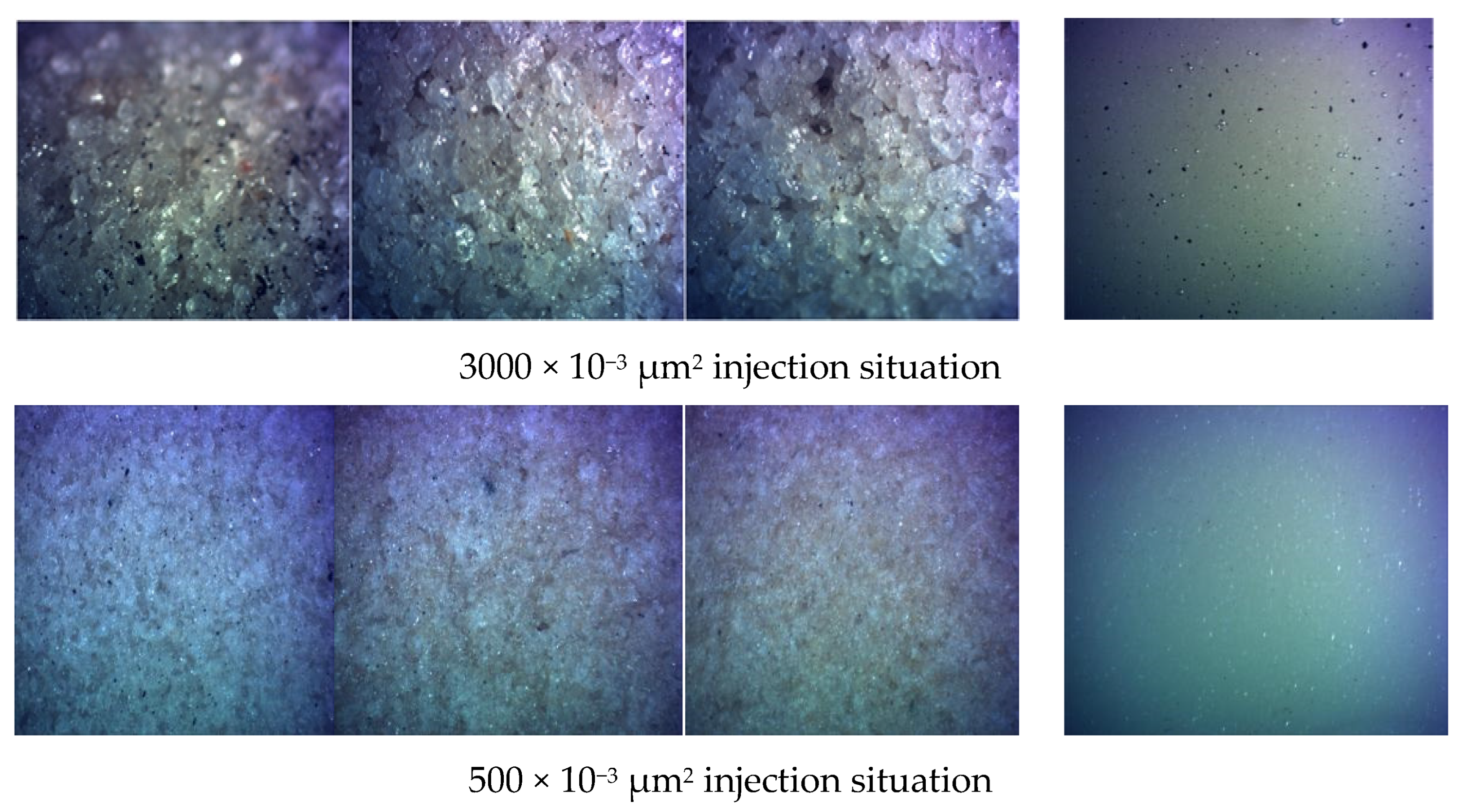
3.2. Injectability of Asphalt Binder and Its Matching Relationship with Formation of Porous Media

After the experiment, the cuboid core was cut open and placed under a microscope to observe the injection of asphalt binder at different positions and whether the produced fluid contained asphalt binder to further judge the injection performance and profile control effect of asphalt binder.
As shown in Figure 5, the 3000 × 10−3 μm2 core was injected with asphalt binder with a diameter of 0.02–0.06 mm, and it can be seen that the injection requirements were met, but there was a large amount of asphalt binder in the produced fluid. Therefore, it was judged that the profile control effect cannot be achieved. A 500 × 10−3 μm2 core injection effect is better, and there is only a small amount of asphalt binder in the produced fluid, which not only meets the injection requirements but also achieves the effect of profile control. It can be seen that for formations with different permeabilities, that there is a matching relationship between asphalt particle size and formation permeability. Based on this, the matching relationship between asphalt particle size and formation permeability experiment was carried out, and the plugging effect of asphalt particle profile control was tested.
Asphalt suspensions of different particle sizes with a concentration of 3500 mg/L were injected at a constant flow rate of 3 mL/min. After the experiment, the pressure difference between the two ends of the core was used to calculate the Kwb (permeability before the injection of asphalt profile control agent), Kwa (after the injection of the asphalt profile control agent, the permeability), resistance coefficient, residual resistance coefficient, plugging rate, and recovery rate increase value—the specific values are shown in Table 3 below.
From the longitudinal analysis of the numerical analysis in Table 3, it can be seen that the larger the permeability is, the larger the particle size range of the asphalt binder that can be injected is. According to the numerical transverse analysis, with the increase of the injected asphalt particle size, the permeability after plugging gradually decreases, and the value of the recovery factor increases gradually. After injection of large-sized asphalt binder, Kwa suddenly becomes smaller. The reason is that the particle size of asphalt is too large, the injection core effect is poor, the injection distance is short, injection is difficult, and end-face aggregation is serious. Based on the above analysis, the values of the permeability matching relationship between asphalt binder of different particle sizes and different homogeneous cores are shown in Table 4 below.
By comprehensively comparing the plugging rate and the enhanced recovery value of asphalt binder with different particle sizes, the optimal particle size of asphalt binder is finally determined to be 0.02–0.06 mm.

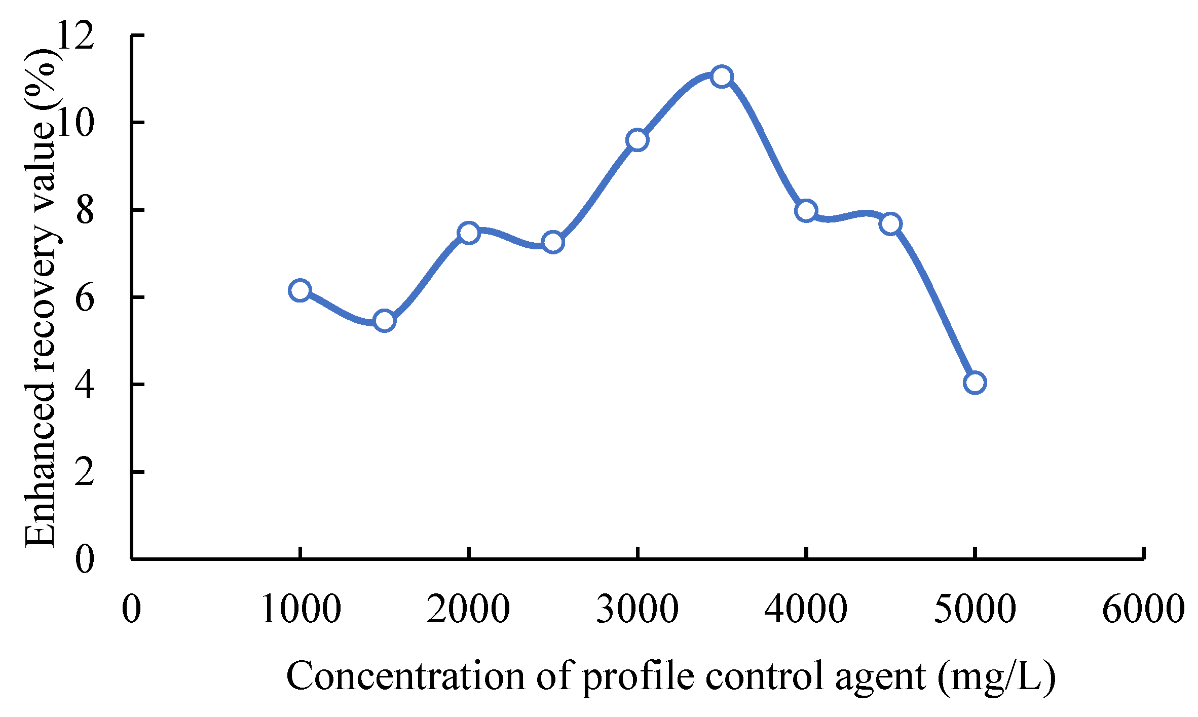
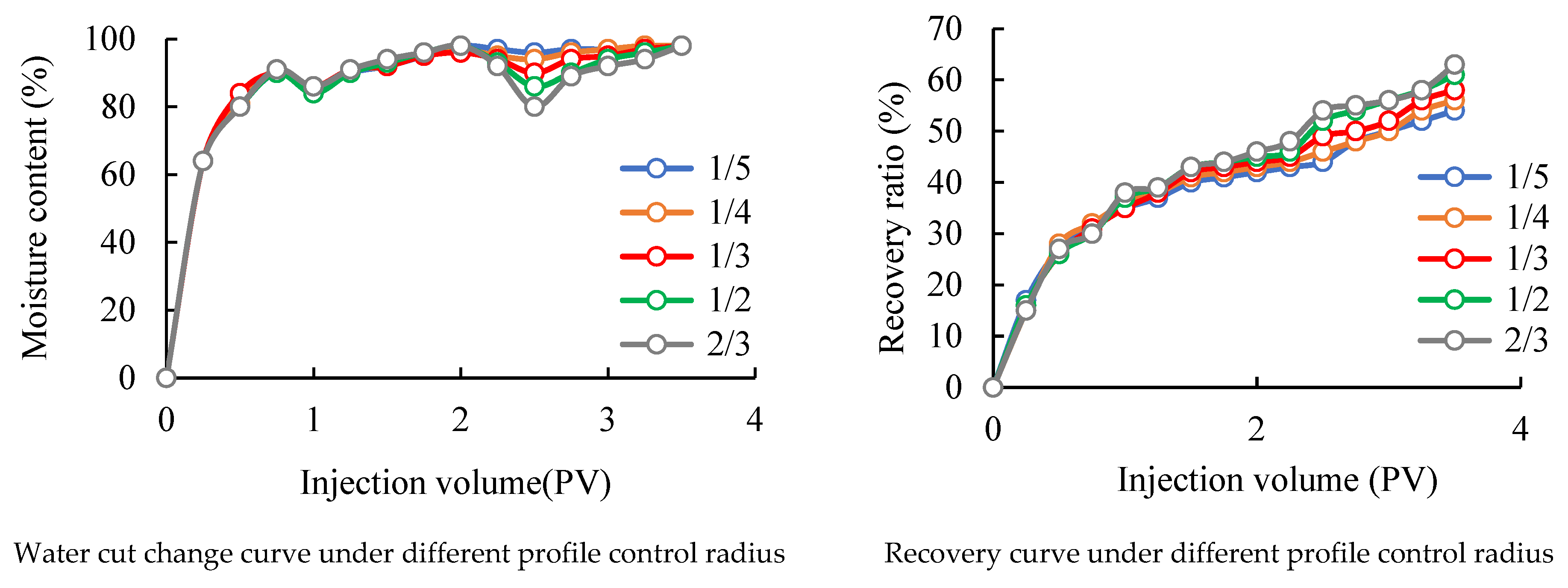
3.3. Optimization of Concentration and Profile Control Radius of Asphalt Particle Profile Control Agent System

Under the constant flow rate of 3 mL/min, 0.2 PV of asphalt particle profile control fluid with different concentrations (1000, 1500, 2000, 2500, 3000, 3500, 4000, 4500, 5000 mg/L) was injected, respectively, and the profiles before and after plugging were calculated, respectively: permeability, water flooding recovery factor, polymer flooding recovery factor, water flooding recovery factor after bitumen injection, and recovery factor enhancement values.
It can be seen from Figure 6 that with the increase of the injected asphalt profile control fluid concentration, the percentage value curve of the recovery factor firstly increased and then decreased. The rate of increase in percentage value is the largest.
Distilled water with different PV numbers was injected into the core after the asphalt profile control agent was injected, and the numerical changes of the injection pressure and calculated permeability at each stage were monitored as shown in Figure 7.
From the smoothness of the curve in Figure 6, it can be seen that when the concentration of the injected asphalt particle profile control fluid is 3500 mg/L and above, the permeability increase after plugging is very small, indicating that 3500 mg/L is ideal. The erosion resistance of the above concentrations is good, and from the perspective of economic cost, combined with the previous analysis, it is determined that the optimal concentration is 3500 mL/L.
According to the requirements of the experimental plan, the optimization experiment of profile control radius was carried out on three-layer heterogeneous oil-saturated square cores. Pressure measuring points of the injection point were set at 1/5, 1/4, 1/3, 1/2, and 2/3 from the center, first performing water flooding, then polymer flooding, and then injecting the preferred asphalt particle profile control fluid for profile control, and then follow-up water flooding to calculate the recovery factor at each stage. The specific experimental numerical results are shown in Table 5.
It can be seen from Table 4 that the size of the profile control radius has a great influence on the oil displacement effect. When the profile control radius is increased from 1/5 to 1/2, the recovery factor increases from 9.8% to 12.11%. However, when the profile control radius was increased from 1/3 to 1/2, the recovery factor increased from 10.59% to 12.11%, and when the profile control radius was increased from 1/2 to 2/3, the recovery factor increased from 12.11% to 12.89%, while the enhanced oil recovery value per unit usage decreased.
In order to more clearly see the change of oil displacement characteristics with the injection of profile control agent under different profile control radii, take the injected PV number as the abscissa, and the water cut and recovery rate as the ordinate as shown in Figure 8.
It can be seen from comparing the curve of water cut that after polymer flooding injects asphalt particle profile control liquid, and then water flooding, the water cut curve first decreases, then rises and finally tends to be flat. With these increases, the moisture content decreases more and more. From the comparison of the recovery factor curve, it can be seen that with the increase of injection, the recovery factor curve has an obvious upward trend, and with the increase of the profile control radius, the recovery factor rises more and more. When the profile control radius increases from 1/2 to 2/3, the increase of the recovery factor becomes smaller. If the profile control radius continues to increase, the increase of the recovery factor becomes slower, and the cost will increase sharply, which is not in line with the actual production. Therefore, it can be determined that the optimum profile control radius of asphalt binder is between 1/3 and 1/2 of the well spacing.

4. Summary and Conclusions

According to the actual situation of high water cut wells in the Lamadian oilfield, this paper optimizes the profile control parameters of asphalt binder, and draws the following conclusions:
(1) The 500 × 10−3 μm2 formation matching particle size is 0.02–0.06 mm, the 1500 × 10−3 μm2 rock formation matching particle size is 0.06–0.1 mm, and the 3000 × 10−3 μm2 oil layer matching particle size is 0.1–0.3 mm.
(2) The injection concentration of the asphalt particle profile control agent system has a certain positive effect on the profile control effect, but when the concentration is greater than a certain value, it will cause blockage formation and reduce the recovery rate. The best applicable concentration in the Lamadian oilfield is 3500 mg/L.
(3) The size of the profile control radius has a great influence on the oil displacement effect. The larger the asphalt injection volume, the larger the profile control radius and the higher the recovery factor. However, considering the economic benefits, the optimal profile control radius is between 1/3 and 1/2 of the well spacing.
(4) This study has certain guiding significance for the application of asphalt particle profile control agent in high water cut wells, and optimizes the profile control parameters of asphalt particles. Some help is provided for the subsequent field application of this technology. However, this paper still has some limitations. This paper does not analyze the influence of slug combination on the oil displacement effect. It is hoped that future researchers can further optimize the parameters of the asphalt particle profile control agent and expand the field application scope of the asphalt particle profile control agent.

Author Contributions

Conceptualization, Q.L.; methodology, K.L.; software, G.S.; validation, G.C.; resources, Y.B.; data curation, N.Z.; writing—original draft preparation, J.W. All authors have read and agreed to the published version of the manuscript.

Funding

This research received no external funding.

Data Availability Statement

Not applicable.

Conflicts of Interest

The authors declare no conflict of interest.

References

  1. Wei, J.; Zhao, X.; Liu, X.Z.X.; Zhang, H.; Jamshid, O.I.J. Methodology for Estimating Strength and Elasticity of Granular Profile Control Agents Used in ASP water Flooding. Chem. Technol. Fuels Oils 2020, 55, 790–799. [Google Scholar]
  2. Zhao, X.; Fu, M.; Wang, Z.; Dong, L.; Tang, J. Research overview of profile control and water shut-off agents for heavy oil thermal recovery. Spec. Oil Gas Reserv. 2011, 20, 1–4. [Google Scholar]
  3. Cao, G.; Cheng, Q.; Liu, Y.; Bu, R.; Zhang, N.; Wang, P. Influencing Factors of Surfactant Stripping Crude Oil and Spontaneous Imbibition Mechanism of Surfactants in a Tight Reservoir. ACS Omega 2022, 7, 19010–19020. [Google Scholar] [CrossRef]
  4. Pu, W.; Wen, C.; Liu, R.; Jin, F.; Wang, C.; Liao, Z. Evaluation of a novel profile control agent for enhancing an oil-recovery application. J. Appl. Polym. Sci. 2016, 133, 43756. [Google Scholar] [CrossRef]
  5. Dong, L.; Wang, M.; He, J.; Ding, M.; Lin, H. Experimental Investigation of Self-Assembled binder on Profile Control in the Fuyu Oilfield. Front. Chem. 2021, 9, 681846. [Google Scholar] [CrossRef] [PubMed]
  6. Chen, X.; Li, Y.; Liu, Z.; Zhang, J.; Chen, C.; Ma, M. Investigation on matching relationship and plugging mechanism of self-adaptive micro-gel (SMG) as a profile control and oil displacement agent. Powder Technol. 2020, 5, 774–784. [Google Scholar] [CrossRef]
  7. Nascimento, D.R.; Oliveira, B.R.; Saide, V.G.P.; Magalhaes, S.C.; Scheid, C.M.; Calcada, L.A. Effects of particle-size distribution and solid additives in the apparent viscosity of drilling fluids. J. Pet. Sci. Eng. 2019, 182, 106275. [Google Scholar] [CrossRef]
  8. Zhang, L.; Zhuang, W.; Nasir, K.; Zheng, L. Effect of stress relaxation and creep recovery on transportation in porous medium and fracture of the millimeter-scale polymer gel binder for conformance control of heterogeneous oil reservoir. J. Pet. Sci. Eng. 2020, 185, 106648. [Google Scholar] [CrossRef]
  9. Ren, C.; Li, J.; Li, Y.; Yuan, J.; Xi, Y.; Xiao, K.; Wang, Y. Experimental Investigation of the Matching Relationship between Asphalt Particle and Reservoir Pore in Profile Control Process. J. Eng. 2016, 2016, 2507316. [Google Scholar] [CrossRef]
  10. Li, Y.; Xiang, G.; Wang, Y.; Li, Y.Y.; Li, J.J. Matching of asphalt binder and formation pores for conformance control treatment in Lamadian Oilfield of Daqing. J. China Univ. Pet. 2015, 39, 92–96. [Google Scholar]
  11. Liu, G.; Jiang, H.; Li, J.; Wang, M.; Chen, F.; Ding, S.; Lu, X. Evaluation of the performance of polymer gels mixed with asphalt particle as a novel composite profile control system. Energy Weekly News 2015, 7, 309–314. [Google Scholar] [CrossRef]
  12. Du, D.; Pu, W.; Tan, X.; Liu, R. Experimental study of secondary crosslinking core-shell hyperbranched associative polymer gel and its profile control performance in low-temperature fractured conglomerate reservoir. J. Pet. Sci. Eng. 2019, 6, 912–920. [Google Scholar] [CrossRef]
  13. Kabir, A.H.; Petronas Carigali Sdn Bhd. Chemical water & gas shut off technology—An overview. In Proceedings of the SPE Asia Pacific Improved Oil Recovery Conference, Kuala Lumpur, Malaysia, 8–9 October 2001. [Google Scholar]
  14. Wu, D.; Zhou, K.; Zhaon, F.; Lu, X.; An, Z.; Liu, S.; Hou, J. Determination of Permeability Contrast Limits for Applying Polymer Solutions and Viscoelastic Particle Suspensions in Heterogeneous Reservoirs. Energy Fuels 2022, 7, 7495–7506. [Google Scholar] [CrossRef]
  15. Shao, M.; Fu, L.; Yue, X. Experimental Study on Aggregation Regulation and Plugging Performance of Nanobinder in Low-permeability Heterogeneous Cores. Chemistryselect 2022, 7, e202104085. [Google Scholar] [CrossRef]
  16. Yu, H.; Gao, M.; Du, C.; Zhang, M. Preparation and properties of flexible particle profile control agent based on waste rubber. Appl. Chem. Ind. 2021, 50, 2985–2988. [Google Scholar]
  17. Yang, C. Development and Application of Profile Control and Oil Displacement Agent Contained Oil Sludge Filled Gel Particle. Oilfield Chem. 2018, 35, 422–426. [Google Scholar]
  18. Wang, C.; Zhang, L.; Ju, G.; Sun, Q. Development and Performance Evaluation of a High-Temperature Profile Control System. ACS Omega 2020, 5, 17828–17838. [Google Scholar] [CrossRef]
  19. Chen, Y.; Wang, K.; Li, G.; Lu, C. Plugging mechanism of large size profile control binder and deep migration performance. Lithol. Reserv. 2019, 31, 159–164. [Google Scholar]
  20. Tan, L.; Chang, L.; Shen, J.; Liu, Y.; Yang, Z.; Liu, C. Evaluation and field application of intercalative gel binder as deep profile control agent. Chem. Eng. Oil Gas 2019, 48, 78–80. [Google Scholar]
  21. Mu, Y.; Wang, B.; Sun, Z. Preparation and study of waste drilling fluid profile control water plugging agent. Reserv. Eval. Dev. 2019, 9, 68–71. [Google Scholar]
  22. Sun, X.; Sun, X.; Xu, Z.; Zhao, S.; Xu, C. PGSS method for preparation of deoiled asphalt particles. J. Chem. Eng. Coll. Univ. 2010, 2, 290–295. [Google Scholar]
Figure 1. Three-section core with diversion section.
Processes 10 01917 g001
Figure 2. Experimental device and process.
Processes 10 01917 g002
Figure 3. Experiment device for optimization of profile control radius.
Processes 10 01917 g003
Figure 4. Size of asphalt binder after adding different concentrations of KCl.
Processes 10 01917 g004
Figure 5. Injection of 0.02–0.06 mm asphalt binder.
Processes 10 01917 g005
Figure 6. Injection concentration-percent recovery rate curve.
Processes 10 01917 g006
Figure 7. Permeability changes with the injection volume of distilled water.
Processes 10 01917 g007
Figure 8. Oil displacement characteristic curves of different profile control radii.
Processes 10 01917 g008
Table 1. Formulation water formula for experiment.
ComponentHCO3−CO32−ClSO42−Ca2+Mg2+Na+Total Salinity
Concentration (mg/L)2400213245365231230008167
Table 2. Suspension of asphalt binder.
Particle Size (mm)Addition Amount (g)Residue Weight (g)Suspension Rate (%)
0–0.0250.19296.16%
0.02–0.0650.31593.70%
0.06–0.150.3593.00%
0.1–0.350.39892.04%
0.3–0.850.49590.10%
Table 3. Experimental results of cores with different permeability.
Permeability
(×10−3 μm2)
Particle Size
(mm)
Kwb
(×10−3 μm2)
Kwa
(×10−3 μm2)
Resistance CoefficientResidual Resistance CoefficientPlugging RateEnhanced Recovery (%)
5000.0251515526.483.260.7112.52
52816925.153.130.6711.69
0.0251514528.503.550.7412.87
50514029.603.630.7513.05
15000.02150578315.591.900.4711.35
150381214.981.860.4510.99
0.02–0.06151568518.022.240.5614.70
150565718.632.310.5815.96
0.06–0.1149766218.372.250.5516.69
151067018.172.280.5816.25
30000.023010138517.552.150.559.92
2995141017.252.170.509.72
0.02–0.063045125019.502.430.6010.95
2990127019.102.350.5910.05
0.06–0.13010110522.102.750.6511.00
3020109622.352.750.6711.93
0.1–0.3299099524.423.050.6411.33
302298524.803.050.6511.76
Table 4. Matching relationship between particle size asphalt binder and permeability.
Penetration
(×10−3 μm2)
Injectable Particle Size
(mm)
Non-Injectable Particle Size
(mm)
5000.02, 0.02–0.060.06–0.1, 0.1–0.3, 0.3–0.8
15000.02, 0.02–0.06, 0.06–0.10.1–0.3, 0.3–0.8
30000.02, 0.02–0.06, 0.06–0.1, 0.1–0.30.3–0.8
Table 5. The recovery degree of different profile control radius at each stage.
Injection RadiusInjection Volume (mL)Waterflood Recovery (%)Polymer Flooding Recovery (%)Ultimate Recovery (%)Recovery
Increase (%)
1/5184.1035.1644.3654.169.80
1/4305.2036.6945.7255.9810.26
1/3528.8535.0747.3657.9510.59
1/21215.2036.7249.1461.2512.11
2/31699.9537.0350.2663.1512.89
Publisher’s Note: MDPI stays neutral with regard to jurisdictional claims in published maps and institutional affiliations.

